Embed Size (px)
Citation preview
PHYSICAL INSIGHT INTO FUEL MIXING ENHANCEMENTWITH BACKWARD-FACING STEP FOR SCRAMJET ENGINES
VIA MULTI-OBJECTIVE DESIGN OPTIMIZATION
H. Ogawa∗, C. Y. Wen†, Y. C. Chang‡
∗School of Aerospace, Mechanical and Manufacturing Engineering, RMIT University,Melbourne, Australia
†Department of Mechanical Engineering, The Hong Kong Polytechnic University, Kowloon,Hung Hom, Hong Kong
‡Department of Aeronautics and Astronautics, National Cheng Kung University, Tainan, Taiwan
Keywords: Fuel injection, Backward-facing step, CFD, Evolutionary algorithms, Surrogate modeling
Abstract
Fuel injection into crossflow behind a backward-facing step is studied by means of multi-objectivedesign optimization, aiming at fuel/air mixingfor supersonic combustion of scramjet propul-sion. A variety of injector configurations havebeen examined in the optimization process usingevolutionary algorithms in conjunction with lo-cal search methods and surrogate modeling. Datamining has been performed by applying statisti-cal techniques including variance-based sensitiv-ity analysis to the surrogate models constructedwith solutions from computational fluid dynam-ics. The injection angle and backward step heighthave been found to be the most influential de-sign parameters on the mixing performance forthe configurations considered in this study.
1 Introduction
Hypersonic air-breathing propulsion offers thepotential for reliable and economical transportfor access to space and high-speed atmosphericflight. In particular, scramjet (Supersonic Com-bustion Ramjet) propulsion is a promising tech-nology that can enable efficient and flexibletransport systems by removing the need to carryoxidizers and other limitations of conventionalrocket engines. The last decade has seen remark-able milestones achieved by various flight exper-
iments including The University of Queensland’sHyShot II in 2002[1, 2], the NASA X-43 vehi-cles in the Hyper-X program in 2004[3], and theBoeing X-51A WaveRider in 2010[4].
The scramjet mechanism critically dependson the sequential process – capture and compres-sion of hypersonic airflow in the inlet, fuel in-jection into the air, supersonic combustion in thechamber, and expansion of combustion productsthrough the nozzle for thrust. Fuel injection playsa major role in the flow process, responsible forefficient combustion and hence overall scramjetperformance[5]. The airflow slows down fromhypersonic to supersonic through the inlet, butfurther deceleration would lead to undesirablehigh static temperature and result in limited heatrelease due to excessive dissociation of nitrogenand oxygen gases[6]. The interactions betweenfuel and air including mixing, ignition and com-bustion occur at an extremely short timescale,rendering the development of efficient and reli-able fuel injection systems of crucial importance.
The significance of fuel injection in airbreath-ing engines has brought about a considerablenumber of mixing techniques. Examples in-clude: traverse/tangential injection through wallorifices[7, 8, 9], streamwise vortices with al-ternating wedges (hypermixers)[10, 11], shock-enhanced mixing with alternative compressionramps and expansion troughs[12], and backward
1
OGAWA, WEN, AND CHANG
transverse/inclined injection in the vicinity of abackward-facing step or a cavity[13, 14, 15, 16].The last method, in particular, offers advantagesin various aspects, in particular, self ignition andflame holding in the recirculation zone down-stream of the step, where injected fuel is mixedwith relatively slow airflow at high temperature.
A recent shock-tunnel experiment conductedby the authors observed strong interactions be-tween recombination shock waves due to thereattachment of the separated shear layer andthe inclined fuel jet adjacent to the reattach-ment point downstream of a backward-facingstep (Fig. 1)[17]. The flow visualization via high-speed Schlieren suggested promising effects ofthe jet interactions on fuel/air mixing enhance-ment owing to the baroclinic torque induced bymisaligned pressure gradient in conjunction withshear-induced Kelvin-Helmholtz vorticity. For-mer research efforts on fuel injection with a back-ward step have been made, with primary focus onthe jet interactions and mixing characteristics forprefixed configurations[13, 14, 15, 16, 17], andno preceding research has studied geometric ef-fects on the mixing performance systematically,to the knowledge of the authors.
Fig. 1 Interactions of recombination shockwaves with fuel injected into supersonic cross-flow behind a backward-facing step[17]
The present numerical study is undertaken toinvestigate the effects of the design parameters onthe fuel/air mixing by means of multi-objectivedesign optimization (MDO) using surrogate-assisted evolutionary algorithms coupled withcomputational fluid dynamics, which has beenapplied extensively to numerous optimizationproblems for scramjet engines[18, 19, 20]. Theresults from are examined by covariance-basedsensitivity analysis using surrogate prediction toextract essential information on key design fac-tors for this fuel mixing method. Flowfields
are visualized and scrutinized for representativeconfigurations in comparison with the referencegeometry in order to elucidate underlying flowphysics that is responsible for the fuel behaviorand mixing characteristics.
2 Approaches
2.1 Configurations and Conditions
x
z
y 0
outflow
(supersonic)
isothermal wall
symmetry
W
L
xj
2rj
fuel
2
fuel l
j
air inflow
H
hs
outflow (supersonic)
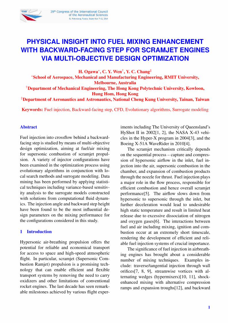
Fig. 2 Schematic of fuel injection into air cross-flow downstream of a backward-facing step
The configuration considered in this study isschematically presented in Fig. 2, as per the set-tings experimental setups[17]. The flow condi-tions considered in this study are shown in Ta-ble 1 in terms of the Mach number (M), staticand total pressures (p and p0), and static and to-tal temperatures (T and T0), assuming sonic fuelinjection into airflow incoming at Mach 2 with adynamic pressure of 418 kPa and Reynolds num-ber of 1.43×10⁷ per unit length. Methane (CH4)is used as fuel to be injected into crossflow of air,where both gases are assumed to be caloricallyperfect with a specific heat ratio γ of 1.32 and 1.4,respectively, in the present study. The fuel injec-tion pressure p j is adjusted according to the in-jector radius r j to maintain the jet-to-freestream
momentum flux ratio J(≡ (ρV 2) j
(ρV 2)∞
)at 1.43.
Table 1 Crossflow air and fuel injection conditionsM p [kPa] p0 [kPa] T [K] T0 [K]
Air 2 150 1174 1100 1980Fuel 1 910 7003 259 425
The floor is taken to be an isothermal wall,with the temperature maintained at 300 K for a
2
Physical Insight into Fuel Mixing with Backward Step for Scramjets via MDO
short test time in the impulse facility, as shownin Fig. 2, which displays the boundary conditionsused in this paper. It also depicts the four de-sign parameters, namely, the angle α j, stream-wise position x j, and radius r j of the fuel injec-tor as well as the height of the backward-facingstep hs. The length (L, after the step), width (W ),height (H) of the computational domain are fixedat 0.055 m, 0.02 m, 0.032 m, respectively, in con-cordance with the experimental setups[17]. Thedomain also include a 5 mm trailing-edge of thebackward step at a height of hs. Imposed at itsentrance as an inflow is the profile of a turbulentboundary layer, which has grown over 30 mmfrom the leading edge of a flat plate, as per theexperimental arrangement.
2.2 Computational Fluid Dynamics
Compressible flowfields in the presence of fuelinjection are computed by utilizing a commercialsolver CFD++ [22], which has been employedby the Australian hypersonics network for scram-jet research due to its demonstrated fidelity inhypersonic aerodynamics[18, 19, 20]. An im-plicit algorithm with second-order spatial accu-racy is used to solve the Navier-Stokes equationsfor viscous flowfields and convergence is accel-erated by the multigrid technique. The bound-ary layer is taken to be fully turbulent and mod-eled by the two-equation SST k-ω RANS model.Steady flowfields are computed in the presentstudy, which focuses on fuel/air mixing purelydue to steady fluid dynamics and interactions, ex-cluding effects of unsteady phenomena such asshear-induced vorticity motion.
Three-dimensional computational meshes aregenerated automatically by Glyph scripting ona commercial grid generator Pointwise[23] forthe fuel injection configuration represented bythe four design variables introduced in the for-mer section. A fully structured mesh comprising1,275,000 cells are generated for each configura-tion, based on the topology and mesh sensitivitystudy described in the preceding studies[20, 21].The computational mesh is superimposed in Fig.2 for the baseline geometry, which correspondsto the experimental model[17].
2.3 Multi-Objective Design Optimization
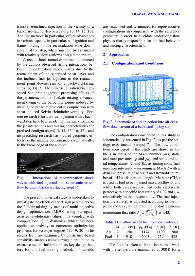
Fig. 3 Optimization chain
In order to conduct a design optimization forthe injector in a coupled MDO/CFD approach,a process chain is set up and implemented, con-sisting of mesh generation (pre-processing), CFDcomputation (evaluation), post-processing andoptimization algorithms, as schematically shownin Figure 3. Design optimization is performedby applying evolutionary algorithms, in particu-lar, the elitist non-dominated sorting genetic al-gorithm (NSGA-II)[24, 25]. It is a population-based approach that evolves the candidate solu-tions in the population pool over generations, en-abling global search. Simulated binary crossoverand polynomial mutation are used as recombina-tion operators at a given probability (1.0 and 0.1,respectively, in this study) with a specified distri-bution index (10 and 20, respectively).
Multiple surrogate models including re-sponse surface models, radial basis function net-works, kriging and multilayer perceptrons, areemployed to mitigate the computational costby replacing the CFD evaluations[26], trainedregularly (every 5 generations in this study).Once surrogate models become available, hy-brid (memetic) optimization is performed by in-corporating local search methods including pat-tern search and sequential quadratic program-ming combined with adaptive weighting into evo-lutionary algorithms[27, 28]. Covariance-basedglobal sensitivity analysis[29, 30] is applied tothe solution archive resulting from CFD evalu-ations so as to investigate the effects of the deci-sion variables (input parameters) on the objectivefunctions (objective functions).
2.4 Design Criteria
The performance of fuel injection is evaluated byquantifying the resultant flowfields with respectto multiple criteria. High total pressure recoveryis a desired feature in fuel mixing so as to enable
3
OGAWA, WEN, AND CHANG
effective combustion and high thrust production.This objective is targeted by minimizing the totalpressure loss defined as ∆p0 ≡ 1−
R
x p0dmR
x=0 p0dm . Fuelpenetration into the crossflow is another impor-tant characteristic of fuel injection. This criterionis assessed by the penetration height defined ashp ≡ max
(z |cCH4>0.1cs
CH4
)at the exit, where cCH4
and csCH4
are the fuel mass fraction and its stoi-chiometric value (0.0548), respectively. It evalu-ates the fuel remaining in the mainstream withoutbeing captured in the recirculation region behindthe backward step.
The mixing efficiency is commonly used toevaluate the mixing ability of transverse fuel in-jection by examining the fuel massflow with re-spect to the stoichiometric ratio for the outflow,but it is not deemed as a suitable criterion forthe current configuration, where the recircula-tion zone plays a major role in fuel mixing andflame holding (in case of ignition and combus-tion). The fuel massflow deficit is thus consid-ered in this study, defined as ∆m f ≡ 1−
R
x dm fR
x=0 dm f,
where m f is the fuel massflow rate. The non-dimensionalized streamwise circulation is em-ployed as the last metric to account for the over-all effects of streamwise vortices, which playsa primary role in the fuel/air mixing[5, 12]. Itis defined as: Γ ≡ 1
udR
x |ωx|dA, where ωx is thestreamwise vorticity, u the crossflow velocity andd the effective injector diameter (1330 m/s and1 mm, respectively).
2.5 Optimization Problem
Multi-objective design optimization is performedwith these parameters, aiming to minimize ∆p0and maximize h f simultaneously. The geomet-ric parameters introduced in Section 2.1 are em-ployed as the decision variables. The optimiza-tion problem statement of this study is expressedas:
minimize: ∆p0−h f
subject to: 30◦ ≤ α j ≤ 90◦
0.005 m ≤ x j ≤ 0.015 m0.0003 m ≤ r j ≤ 0.001 m0.0025 m ≤ hs ≤ 0.01 m
3 Results
3.1 Design Optimization
0.05 0.06 0.07 0.08 0.09 0.1 0.11−11
−10
−9
−8
−7
−6
−5
−4
−3
−2
−1
x 10−3
p0
− h
p [m]
feasible
non−dominated
Δ
S1
S2
baseline
selected
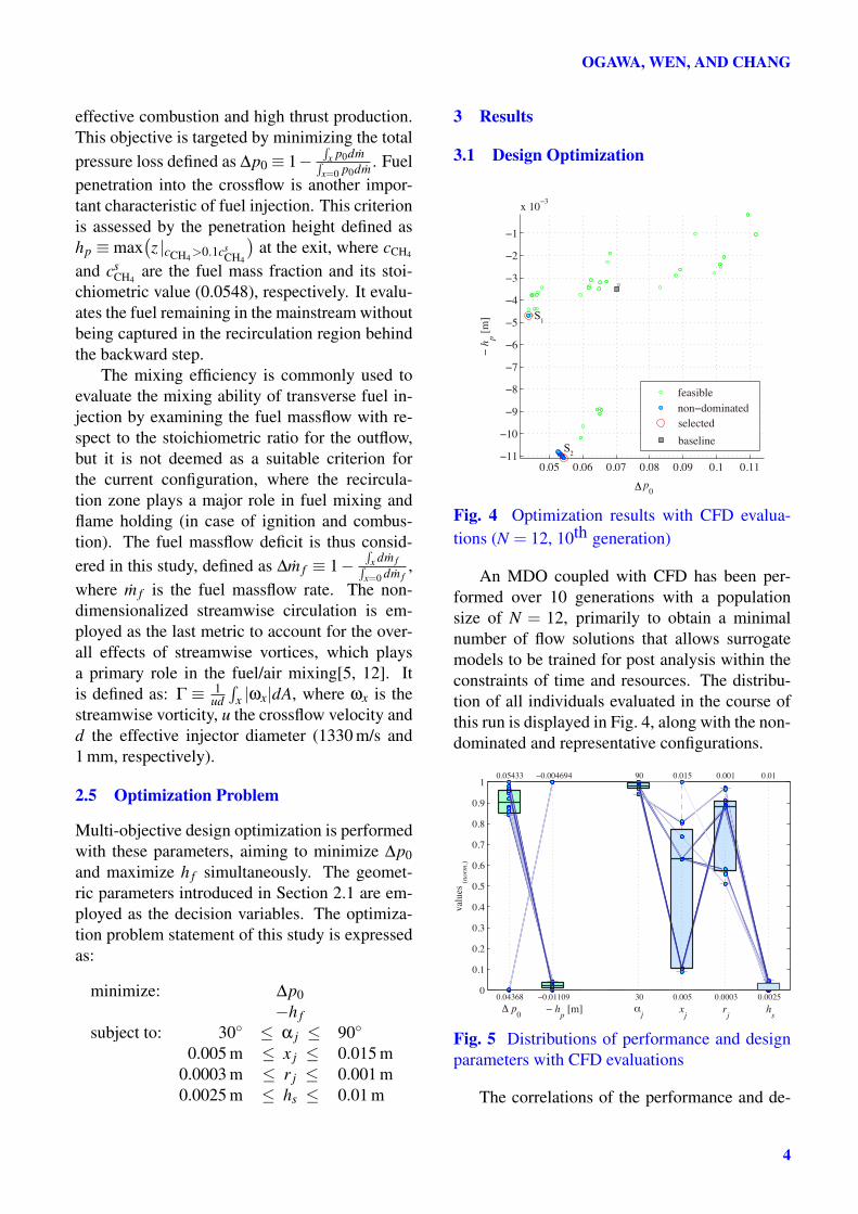
Fig. 4 Optimization results with CFD evalua-tions (N = 12, 10th generation)
An MDO coupled with CFD has been per-formed over 10 generations with a populationsize of N = 12, primarily to obtain a minimalnumber of flow solutions that allows surrogatemodels to be trained for post analysis within theconstraints of time and resources. The distribu-tion of all individuals evaluated in the course ofthis run is displayed in Fig. 4, along with the non-dominated and representative configurations.
0
0.1
0.2
0.3
0.4
0.5
0.6
0.7
0.8
0.9
1
Δ p0
0.04368
0.05433
− hp [m]
−0.01109
−0.004694
αj
30
90
xj
0.005
0.015
rj
0.0003
0.001
hs
0.0025
0.01
valu
es
(no
rm.)
Fig. 5 Distributions of performance and designparameters with CFD evaluations
The correlations of the performance and de-
4
Physical Insight into Fuel Mixing with Backward Step for Scramjets via MDO
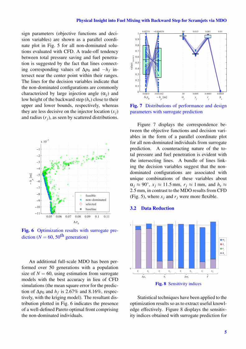
sign parameters (objective functions and deci-sion variables) are shown as a parallel coordi-nate plot in Fig. 5 for all non-dominated solu-tions evaluated with CFD. A trade-off tendencybetween total pressure saving and fuel penetra-tion is suggested by the fact that lines connect-ing corresponding values of ∆p0 and −h f in-tersect near the center point within their ranges.The lines for the decision variables indicate thatthe non-dominated configurations are commonlycharacterized by large injection angle (α j) andlow height of the backward step (hs) close to theirupper and lower bounds, respectively, whereasthey are less decisive on the injector location (x j)and radius (r j), as seen by scattered distributions.
0.05 0.06 0.07 0.08 0.09 0.1 0.11−11
−10
−9
−8
−7
−6
−5
−4
−3
−2
−1
x 10−3
p0
− h
p [m]
feasible
non−dominated
baseline
selected
Δ
S1
S2
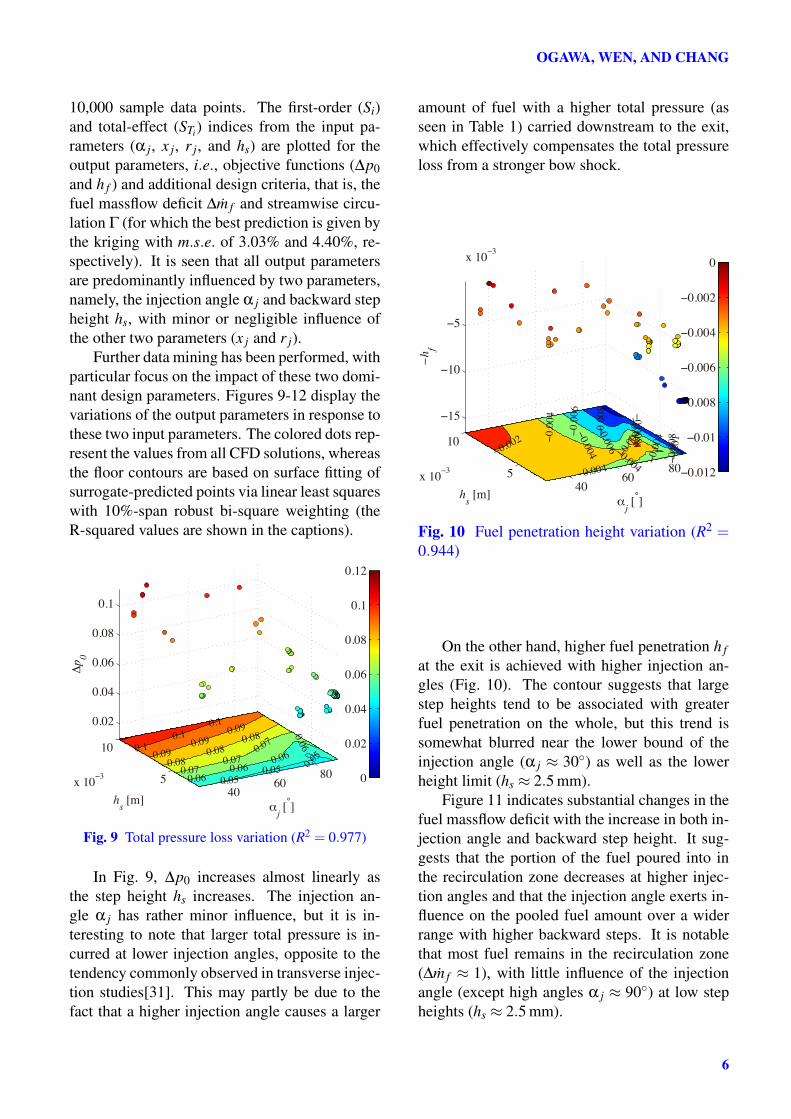
Fig. 6 Optimization results with surrogate pre-diction (N = 60, 50th generation)
An additional full-scale MDO has been per-formed over 50 generations with a populationsize of N = 60, using estimation from surrogatemodels with the best accuracy in lieu of CFDsimulations (the mean square error for the predic-tion of ∆p0 and h f is 2.67% and 8.16%, respec-tively, with the kriging model). The resultant dis-tribution plotted in Fig. 6 indicates the presenceof a well-defined Pareto optimal front comprisingthe non-dominated individuals.
0
0.1
0.2
0.3
0.4
0.5
0.6
0.7
0.8
0.9
1
Δ p0
0.0433
0.05331
− hp [m]
−0.01102
−0.004834
αj
30
90
xj
0.005
0.015
rj
0.0003
0.001
hs
0.0025
0.01
valu
es
(no
rm.)
Fig. 7 Distributions of performance and designparameters with surrogate prediction
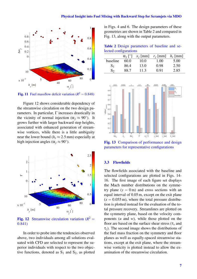
Figure 7 displays the correspondence be-tween the objective functions and decision vari-ables in the form of a parallel coordinate plotfor all non-dominated individuals from surrogateprediction. A counteracting nature of the to-tal pressure and fuel penetration is evident withthe intersecting lines. A bundle of lines link-ing the decision variables suggest that the non-dominated configurations are associated withunique combinations of these variables aboutα j ≈ 90◦, x j ≈ 11.5 mm, r j ≈ 1 mm, and hs ≈2.5 mm, in contrast to the MDO results from CFD(Fig. 5), where x j and r j were more flexible.
3.2 Data Reduction
0
1
Si S
T i S
i S
T i S
i S
T i S
i S
T i
αj
xj
rj
hs
p0 hf mf
Fig. 8 Sensitivity indices
Statistical techniques have been applied to theoptimization results so as to extract useful knowl-edge effectively. Figure 8 displays the sensitiv-ity indices obtained with surrogate prediction for
5
OGAWA, WEN, AND CHANG
10,000 sample data points. The first-order (Si)and total-effect (STi) indices from the input pa-rameters (α j, x j, r j, and hs) are plotted for theoutput parameters, i.e., objective functions (∆p0and h f ) and additional design criteria, that is, thefuel massflow deficit ∆m f and streamwise circu-lation Γ (for which the best prediction is given bythe kriging with m.s.e. of 3.03% and 4.40%, re-spectively). It is seen that all output parametersare predominantly influenced by two parameters,namely, the injection angle α j and backward stepheight hs, with minor or negligible influence ofthe other two parameters (x j and r j).
Further data mining has been performed, withparticular focus on the impact of these two domi-nant design parameters. Figures 9-12 display thevariations of the output parameters in response tothese two input parameters. The colored dots rep-resent the values from all CFD solutions, whereasthe floor contours are based on surface fitting ofsurrogate-predicted points via linear least squareswith 10%-span robust bi-square weighting (theR-squared values are shown in the captions).
4060
805
10
x 10−3
0.02
0.04
0.06
0.08
0.1
0.05
0.0
6
0.06
0.05
αj [°]
0.070.08
0.06
0.09
0.07
0.05
0.08
0.1
0.09
0.060.07
0.1
0.080.09
hs [m]
0.1
Δp
0
0
0.02
0.04
0.06
0.08
0.1
0.12
Fig. 9 Total pressure loss variation (R2 = 0.977)
In Fig. 9, ∆p0 increases almost linearly asthe step height hs increases. The injection an-gle α j has rather minor influence, but it is in-teresting to note that larger total pressure is in-curred at lower injection angles, opposite to thetendency commonly observed in transverse injec-tion studies[31]. This may partly be due to thefact that a higher injection angle causes a larger
amount of fuel with a higher total pressure (asseen in Table 1) carried downstream to the exit,which effectively compensates the total pressureloss from a stronger bow shock.
4060
805
10
x 10−3
−15
−10
−5
x 10−3
−0.0
1−
0.0
08
−0.0
04
−0.0
08
−0.0
06
−0.004
−0.
004
αj [°]
−0.0
06
−0.0
08
−0.004
−0.0
04
−0.0
06
−0.0
04
−0.002
hs [m]
−h
f
−0.012
−0.01
−0.008
−0.006
−0.004
−0.002
0
Fig. 10 Fuel penetration height variation (R2 =0.944)
On the other hand, higher fuel penetration h fat the exit is achieved with higher injection an-gles (Fig. 10). The contour suggests that largestep heights tend to be associated with greaterfuel penetration on the whole, but this trend issomewhat blurred near the lower bound of theinjection angle (α j ≈ 30◦) as well as the lowerheight limit (hs ≈ 2.5 mm).
Figure 11 indicates substantial changes in thefuel massflow deficit with the increase in both in-jection angle and backward step height. It sug-gests that the portion of the fuel poured into inthe recirculation zone decreases at higher injec-tion angles and that the injection angle exerts in-fluence on the pooled fuel amount over a widerrange with higher backward steps. It is notablethat most fuel remains in the recirculation zone(∆m f ≈ 1), with little influence of the injectionangle (except high angles α j ≈ 90◦) at low stepheights (hs ≈ 2.5 mm).
6
Physical Insight into Fuel Mixing with Backward Step for Scramjets via MDO
4060
805
10
x 10−3
0
0.2
0.4
0.6
0.8
0.4
0.1
0.2
0.3
0.50.60.7
0.80.50.40
.60.30.4
0.9
0.1
0.20.30.5
αj [°]
0.60.70.8
0.4
0.10
.20.3
0.9
0.5
0.6
0.4
0.70.80.9
hs [m]
Δm
f
0
0.2
0.4
0.6
0.8
1
Fig. 11 Fuel massflow deficit variation (R2 = 0.848)
Figure 12 shows considerable dependency ofthe streamwise circulation on the two design pa-rameters. In particular, Γ increases drastically inthe vicinity of normal injection (α j ≈ 90◦). Itgrows further with larger backward step heights,associated with enhanced generation of stream-wise vortices, while there is a little ambiguitynear the lower bound (hs ≈ 2.5 mm) especially athigh injection angles (α j ≈ 90◦).
4060
805
10
x 10−3
0
1
2
1.5
1.2
2.10.9
1.8
0.61.5
0.3
1.2
2.72.4
0.90.6
αj [°]
2.11.8
0.3
0.3
1.5
2.7
1.2
2.4
0.9
2.1
0.61.8
0.3
1.5
0.3
1.2
0.90.6
0.3
hs [m]
Γ
0
0.5
1
1.5
2
2.5
Fig. 12 Streamwise circulation variation (R2 =0.841)
In order to probe into the tendencies observedabove, two individuals among all solutions eval-uated with CFD are selected to represent the su-perior individuals with respect to the two objec-tive functions, denoted as S1 and S2, as plotted
in Figs. 4 and 6. The design parameters of thesegeometries are shown in Table 2 and compared inFig. 13, along with the output parameters.
Table 2 Design parameters of baseline and se-lected configurations
α j [◦] x j [mm] r j [mm] hs [mm]baseline 60.0 10.0 1.00 5.00
S1 86.4 13.0 0.98 2.50S2 88.7 11.3 0.91 2.85
0
0.1
0.2
0.3
0.4
0.5
0.6
0.7
0.8
0.9
1
valu
es
(norm
.)
0
0.12
Δp0
0
0.012
hf
0
1
Δmf
0
2.7
Γ
30
90
αj [°]
0.005
0.015
xj [m]
0.0003
0.001
rj [m]
0.0025
0.01
hs [m]
S1
S2
baseline
Fig. 13 Comparison of performance and designparameters for representative configurations
3.3 Flowfields
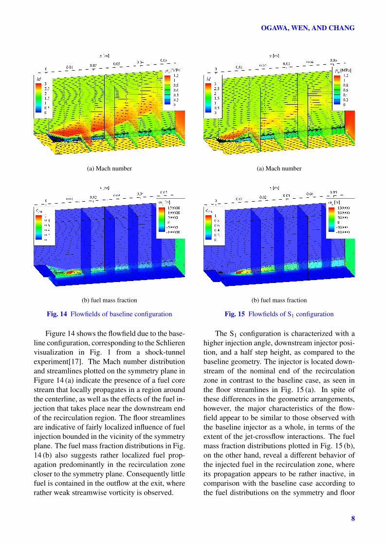
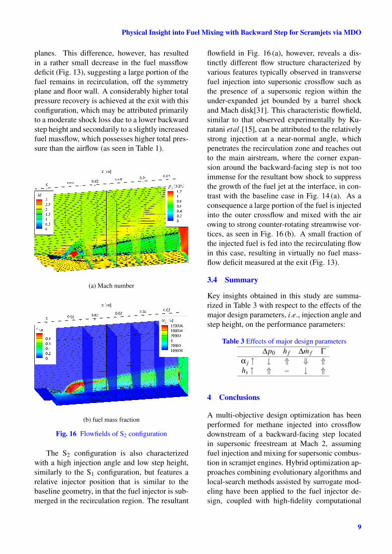
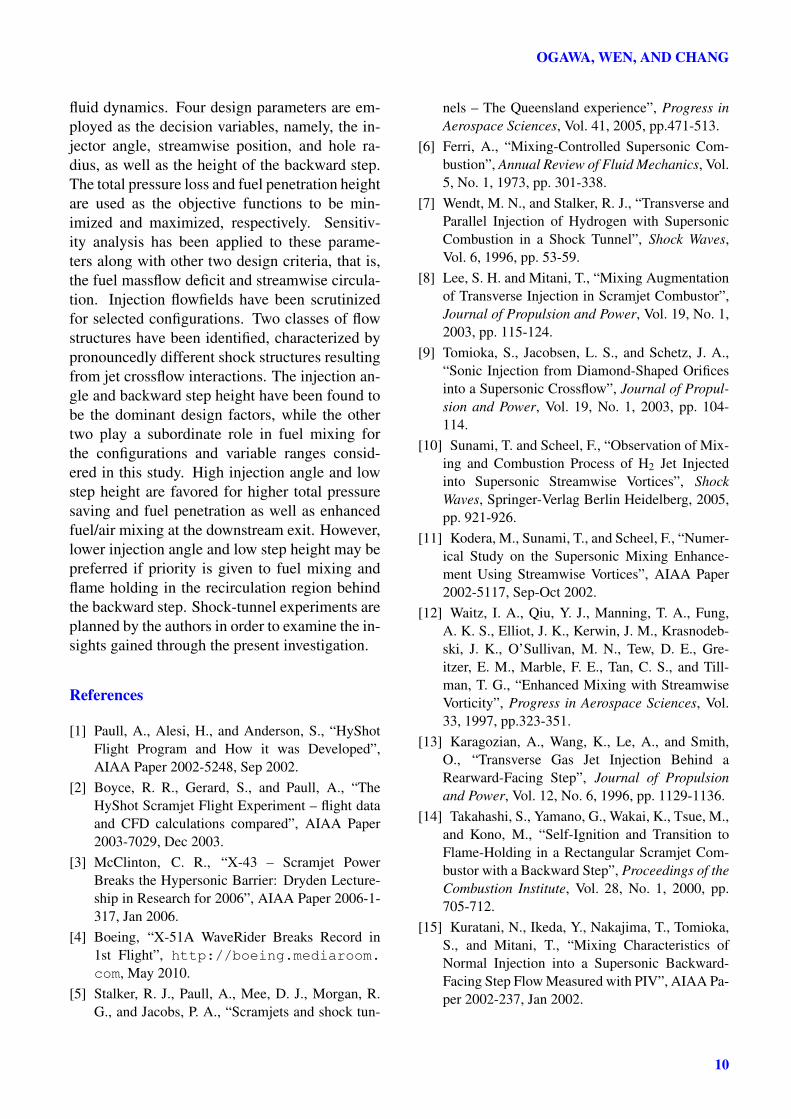
The flowfields associated with the baseline andselected configurations are plotted in Figs. 14-16. The first image of each figure set displaysthe Mach number distributions on the symme-try plane (y = 0 m) and cross sections with anequal interval of 0.05 m, except on the exit plane(x = 0.055 m), where the total pressure distribu-tion is plotted instead for the evaluation of the to-tal pressure recovery. Streamlines are plotted onthe symmetry plane, based on the velocity com-ponents (u and w), while those plotted on thefloor are based on the surface shear stress (τx andτz). The second image shows the distributions ofthe fuel mass fraction on the symmetry and floorplanes as well as equally-spaced streamwise sta-tions, except at the exit plane, where the stream-wise vorticity is plotted instead to allow the ex-amination of the streamwise circulation.
7
OGAWA, WEN, AND CHANG
(a) Mach number
(b) fuel mass fraction
Fig. 14 Flowfields of baseline configuration
Figure 14 shows the flowfield due to the base-line configuration, corresponding to the Schlierenvisualization in Fig. 1 from a shock-tunnelexperiment[17]. The Mach number distributionand streamlines plotted on the symmetry plane inFigure 14 (a) indicate the presence of a fuel corestream that locally propagates in a region aroundthe centerline, as well as the effects of the fuel in-jection that takes place near the downstream endof the recirculation region. The floor streamlinesare indicative of fairly localized influence of fuelinjection bounded in the vicinity of the symmetryplane. The fuel mass fraction distributions in Fig.14 (b) also suggests rather localized fuel prop-agation predominantly in the recirculation zonecloser to the symmetry plane. Consequently littlefuel is contained in the outflow at the exit, whererather weak streamwise vorticity is observed.
(a) Mach number
(b) fuel mass fraction
Fig. 15 Flowfields of S1 configuration
The S1 configuration is characterized with ahigher injection angle, downstream injector posi-tion, and a half step height, as compared to thebaseline geometry. The injector is located down-stream of the nominal end of the recirculationzone in contrast to the baseline case, as seen inthe floor streamlines in Fig. 15 (a). In spite ofthese differences in the geometric arrangements,however, the major characteristics of the flow-field appear to be similar to those observed withthe baseline injector as a whole, in terms of theextent of the jet-crossflow interactions. The fuelmass fraction distributions plotted in Fig. 15 (b),on the other hand, reveal a different behavior ofthe injected fuel in the recirculation zone, whereits propagation appears to be rather inactive, incomparison with the baseline case according tothe fuel distributions on the symmetry and floor
8
Physical Insight into Fuel Mixing with Backward Step for Scramjets via MDO
planes. This difference, however, has resultedin a rather small decrease in the fuel massflowdeficit (Fig. 13), suggesting a large portion of thefuel remains in recirculation, off the symmetryplane and floor wall. A considerably higher totalpressure recovery is achieved at the exit with thisconfiguration, which may be attributed primarilyto a moderate shock loss due to a lower backwardstep height and secondarily to a slightly increasedfuel massflow, which possesses higher total pres-sure than the airflow (as seen in Table 1).
(a) Mach number
(b) fuel mass fraction
Fig. 16 Flowfields of S2 configuration
The S2 configuration is also characterizedwith a high injection angle and low step height,similarly to the S1 configuration, but features arelative injector position that is similar to thebaseline geometry, in that the fuel injector is sub-merged in the recirculation region. The resultant
flowfield in Fig. 16 (a), however, reveals a dis-tinctly different flow structure characterized byvarious features typically observed in transversefuel injection into supersonic crossflow such asthe presence of a supersonic region within theunder-expanded jet bounded by a barrel shockand Mach disk[31]. This characteristic flowfield,similar to that observed experimentally by Ku-ratani etal.[15], can be attributed to the relativelystrong injection at a near-normal angle, whichpenetrates the recirculation zone and reaches outto the main airstream, where the corner expan-sion around the backward-facing step is not tooimmense for the resultant bow shock to suppressthe growth of the fuel jet at the interface, in con-trast with the baseline case in Fig. 14 (a). As aconsequence a large portion of the fuel is injectedinto the outer crossflow and mixed with the airowing to strong counter-rotating streamwise vor-tices, as seen in Fig. 16 (b). A small fraction ofthe injected fuel is fed into the recirculating flowin this case, resulting in virtually no fuel mass-flow deficit measured at the exit (Fig. 13).
3.4 Summary
Key insights obtained in this study are summa-rized in Table 3 with respect to the effects of themajor design parameters, i.e., injection angle andstep height, on the performance parameters:
Table 3 Effects of major design parameters∆p0 h f ∆m f Γ
α j ↑ ↓ ⇑ ⇓ ⇑hs ↑ ⇑ – ↓ ⇑
4 Conclusions
A multi-objective design optimization has beenperformed for methane injected into crossflowdownstream of a backward-facing step locatedin supersonic freestream at Mach 2, assumingfuel injection and mixing for supersonic combus-tion in scramjet engines. Hybrid optimization ap-proaches combining evolutionary algorithms andlocal-search methods assisted by surrogate mod-eling have been applied to the fuel injector de-sign, coupled with high-fidelity computational
9
OGAWA, WEN, AND CHANG
fluid dynamics. Four design parameters are em-ployed as the decision variables, namely, the in-jector angle, streamwise position, and hole ra-dius, as well as the height of the backward step.The total pressure loss and fuel penetration heightare used as the objective functions to be min-imized and maximized, respectively. Sensitiv-ity analysis has been applied to these parame-ters along with other two design criteria, that is,the fuel massflow deficit and streamwise circula-tion. Injection flowfields have been scrutinizedfor selected configurations. Two classes of flowstructures have been identified, characterized bypronouncedly different shock structures resultingfrom jet crossflow interactions. The injection an-gle and backward step height have been found tobe the dominant design factors, while the othertwo play a subordinate role in fuel mixing forthe configurations and variable ranges consid-ered in this study. High injection angle and lowstep height are favored for higher total pressuresaving and fuel penetration as well as enhancedfuel/air mixing at the downstream exit. However,lower injection angle and low step height may bepreferred if priority is given to fuel mixing andflame holding in the recirculation region behindthe backward step. Shock-tunnel experiments areplanned by the authors in order to examine the in-sights gained through the present investigation.
References
[1] Paull, A., Alesi, H., and Anderson, S., “HyShotFlight Program and How it was Developed”,AIAA Paper 2002-5248, Sep 2002.
[2] Boyce, R. R., Gerard, S., and Paull, A., “TheHyShot Scramjet Flight Experiment – flight dataand CFD calculations compared”, AIAA Paper2003-7029, Dec 2003.
[3] McClinton, C. R., “X-43 – Scramjet PowerBreaks the Hypersonic Barrier: Dryden Lecture-ship in Research for 2006”, AIAA Paper 2006-1-317, Jan 2006.
[4] Boeing, “X-51A WaveRider Breaks Record in1st Flight”, http://boeing.mediaroom.com, May 2010.
[5] Stalker, R. J., Paull, A., Mee, D. J., Morgan, R.G., and Jacobs, P. A., “Scramjets and shock tun-
nels – The Queensland experience”, Progress inAerospace Sciences, Vol. 41, 2005, pp.471-513.
[6] Ferri, A., “Mixing-Controlled Supersonic Com-bustion”, Annual Review of Fluid Mechanics, Vol.5, No. 1, 1973, pp. 301-338.
[7] Wendt, M. N., and Stalker, R. J., “Transverse andParallel Injection of Hydrogen with SupersonicCombustion in a Shock Tunnel”, Shock Waves,Vol. 6, 1996, pp. 53-59.
[8] Lee, S. H. and Mitani, T., “Mixing Augmentationof Transverse Injection in Scramjet Combustor”,Journal of Propulsion and Power, Vol. 19, No. 1,2003, pp. 115-124.
[9] Tomioka, S., Jacobsen, L. S., and Schetz, J. A.,“Sonic Injection from Diamond-Shaped Orificesinto a Supersonic Crossflow”, Journal of Propul-sion and Power, Vol. 19, No. 1, 2003, pp. 104-114.
[10] Sunami, T. and Scheel, F., “Observation of Mix-ing and Combustion Process of H2 Jet Injectedinto Supersonic Streamwise Vortices”, ShockWaves, Springer-Verlag Berlin Heidelberg, 2005,pp. 921-926.
[11] Kodera, M., Sunami, T., and Scheel, F., “Numer-ical Study on the Supersonic Mixing Enhance-ment Using Streamwise Vortices”, AIAA Paper2002-5117, Sep-Oct 2002.
[12] Waitz, I. A., Qiu, Y. J., Manning, T. A., Fung,A. K. S., Elliot, J. K., Kerwin, J. M., Krasnodeb-ski, J. K., O’Sullivan, M. N., Tew, D. E., Gre-itzer, E. M., Marble, F. E., Tan, C. S., and Till-man, T. G., “Enhanced Mixing with StreamwiseVorticity”, Progress in Aerospace Sciences, Vol.33, 1997, pp.323-351.
[13] Karagozian, A., Wang, K., Le, A., and Smith,O., “Transverse Gas Jet Injection Behind aRearward-Facing Step”, Journal of Propulsionand Power, Vol. 12, No. 6, 1996, pp. 1129-1136.
[14] Takahashi, S., Yamano, G., Wakai, K., Tsue, M.,and Kono, M., “Self-Ignition and Transition toFlame-Holding in a Rectangular Scramjet Com-bustor with a Backward Step”, Proceedings of theCombustion Institute, Vol. 28, No. 1, 2000, pp.705-712.
[15] Kuratani, N., Ikeda, Y., Nakajima, T., Tomioka,S., and Mitani, T., “Mixing Characteristics ofNormal Injection into a Supersonic Backward-Facing Step Flow Measured with PIV”, AIAA Pa-per 2002-237, Jan 2002.
10
Physical Insight into Fuel Mixing with Backward Step for Scramjets via MDO
[16] Wu, J., Wang, H., Sun, M., Zhang, S., and Wang,Z., “Mixing Characteristics of Transverse JetInjection into Supersonic Flow after Rearward-Facing Step”, Advances in Mechanical Engineer-ing, Vol. 2013, Article ID 762595, 7 pages, 2013.
[17] Wen, C. Y., Chang, Y. C., Su, Y. H., and Yuan,H. F., “The Effect of the Recombination Shockbehind a Backward Step on the Mixing Charac-teristics of an Inclined Sonic Methane Jet in a Su-personic Crossflow”, ISSW Paper 0246-000284,Jul 2013.
[18] Ogawa, H. and Boyce, R. R., “Physical Insightinto Scramjet Inlet Behavior via Multi-ObjectiveDesign Optimization”, AIAA Journal, Vol. 50,No. 8, 2012, pp. 1773-1783.
[19] Ogawa, H. and Boyce, R. R., “Nozzle De-sign Optimization for Axisymmetric Scramjetsby Using Surrogate-Assisted Evolutionary Algo-rithms”, Journal of Propulsion and Power, Vol.28, No. 6, 2012, pp. 1324-1338.
[20] Ogawa, H. and Boyce, R. R., “Multi-ObjectiveDesign Optimization of Fuel Injection for MixingEnhancement in Scramjets by Using Surrogate-Assisted Evolutionary Algorithms”, AIAA Paper2012-5815, Sep 2012.
[21] Ogawa, H. and Boyce, R. R., “ComputationalInvestigation of Fuel Injection with Various In-jector Geometries and Mixing into HypersonicCrossflow in Scramjet Engines”, AIAA Paper2013-0115, Jan 2013.
[22] CFD++, Software Package, Ver.12.1, MetacompTechnologies Inc., CA, 2012.
[23] Pointwise, Software Package, Ver.17.1, Point-wise Inc., TX, 2013.
[24] Ray, T. and Smith, W., “A Surrogate AssistedParallel Multiobjective Evolutionary Algorithmfor Robust Engineering Design”, EngineeringOptimization, Vol.38, No.8, 2006, pp.997-1011.
[25] Ray, T., Isaacs, A., and Smith, W., “Multi-objective optimization using surrogate as-sisted evolutionary algorithm”, (IntroductionG.P.Rangaiah), Multi-objective Optimization:Techniques and Applications in Chemical En-gineering, World Scientific, Singapore, 2008,pp.131-151.
[26] Queipo, N. V., Haftka, R. T., Shyy, W., Goel, T.,Vaidyanathan, R., and Tucker, P. K., “Surrogate-based analysis and optimization”, Progress inAerospace Sciences, Vol.41, 2005, pp.1-28.
[27] Alsumait, J. S., Sykulski, J. K., and Al-Othman,A. K., “A Hybrid GA-PS-SQP Method to SolvePower System Valve-Point Economic DispatchProblems”, Applied Energy, Vol. 87, No, 5, 2010,pp. 1773-1781.
[28] Li, H. and Landa-Silva, D., “An Adaptive Evolu-tionary Multi-Objective Approach Based on Sim-ulated Annealing”, Evolutionary Computation,Vol. 19, No. 4, 2011, pp. 561-595.
[29] Saltelli, A., “Making best use of model evalu-ations to compute sensitivity indices”, ComputerPhysics Communications, Vol. 145, No. 2, 2002,pp. 280-297.
[30] Saltelli, A., Ratto, M., Andres, T., Compolongo,F., Cariboni, J., Gatelli, D., Saisana, M., andTarantola, S., Global Sensitivity Analysis. ThePrimer, Wiley, England, 2008.
[31] Gruber, M. R., Nejad, A. S., Chen, T. H., andDutton, J. C., “Mixing and Penetration Studies ofSonic Jets in a Mach 2 Freestream”, Journal ofPropulsion and Power, Vol. 11, No. 2, 1995, pp.315-323.
5 Acknowledgements
The authors are grateful to A/Prof. T. Rayand Dr. A. Isaacs at UNSW Canberra for pro-viding the MDO framework developed in thegroup. We wish to acknowledge the supportof the Australian Research Council through theDECRA (Discovery Early Career ResearcherAward) Grant No. DE120102277 for Dr. Ogawa.
6 Contact Author Email Address
mailto: [email protected]
Copyright Statement
The authors confirm that they, and/or their company or or-ganization, hold copyright on all of the original materialincluded in this paper. The authors also confirm that theyhave obtained permission, from the copyright holder of anythird party material included in this paper, to publish it aspart of their paper. The authors confirm that they give per-mission, or have obtained permission from the copyrightholder of this paper, for the publication and distribution ofthis paper as part of the ICAS 2014 proceedings or as indi-vidual off-prints from the proceedings.
11