Embed Size (px)
Citation preview

Physical Layer Testing of Passive OpticalNetwork (PON) Modules
Application Note
Introduction
A Passive Optical Network (PON1) is an access technology based on thespecification developed by the FullService Access Network (FSAN) vendor consortium. The ITU-T subse-quently ratified PONs in the G.983.1Recommendation.Passive is the key word here: PONuses small, inexpensive optical split-ters, rather than the relatively large,expensive, and power-hungry opticalrepeaters used in more traditionaloptical networks.
PON network components consist ofOptical Line Terminals (OLTs),Optical Network Terminals (ONTs),Optical Network Units (ONUs), andpassive splitters. As shown in Figure 2 the OLT islocated in the carrier's Central Office(CO) in a telco application, or at aCATV provider's head end. The ONU or ONT terminates the circuit at the subscriber's end. An ONT terminates the circuit on thepremises in Fiber-To-The-Premises(FTTP) set-ups, where it interfacesthe optical fiber to the copper wire.Figure 1: Local Access Technologies
PON Architecture
ApplicationNote_PON 29.06.2005 16:38 Uhr Seite 1

2
An ONU is used in Fiber-To-The-Curb(FTTC) set-ups. In this case, the fiber stops at the curb, with the restof the local loop provided overembedded copper-UTP in conven-tional telco networks and coax inCATV networks. An ONU is also usedin FTTN (Fiber-To-The-Neighborhood)set-ups. In this case, it is locatedcentrally in the neighborhood, withthe rest of the local loop providedover embedded coax or UTP. WhileFTTN maximizes the use of embed-ded cable, and therefore minimizesthe costs associated with cablereplacement, it compromises per-formance to some extent. The passive optical splitter sits inthe local loop between the OLT andthe ONUs or ONTs. The splitterdivides the downstream signal fromthe OLT at the network edge intomultiple, identical signals broadcastto the ONUs. Each ONU is respon-sible for finding the data intendedfor it, and ignoring all others. Upstream signals are governed bytime-division multiple access(TDMA),with the transmitters in the ONUsoperating in burst mode.FSAN supports both symmetric andasymmetric modes. Current FSANimplementations are generally asym-metric, running at speeds of 622 Mbpsdownstream at wavelengths between1480 nm and 1580 nm, and 155 Mbpsupstream, between 1260 nm and1360 nm. Upstream and downstreamtransmissions can be on separatefibers, or can share a single fiber using Wavelength DivisionMultiplexing (WDM). As PON is a passive network tech-nology, the network components donot amplify the signal. This thereforelimits trunk lengths and the numberof signal splits. At current speedsand with current splitter technolo-gies, FSAN trunk lengths can be upto 20 km, and each trunk can support as many as 32 users and 64 endpoints.
Figure 2: PON Architecture
ApplicationNote_PON 29.06.2005 16:38 Uhr Seite 2
Physical Layer Testing of PON Modules Application Note

3
PON Module Basics
The first generation of PONs useddata rates from 12 Mb/s to 155 Mb/sand scalable frame sizes, such as4012 bits.The next generation Broadband PON(BPON, also referred to as APON)used data rates from 155 Mb/s to 622 Mb/s and used ATM cells fortransmission. These provided eithersymmetric 155 Mb/s, or asymmetric155 Mb upstream, 622 Mb/s down-stream. The data was assigned to fixed time-slot of 56 ATM cells (= 23744 bits).
EPON systems use Ethernet frameddata. For 1 Gb/s data rate, this takes1.25 Gb/s because of 8b/10b coding.With Grant/Request handling EPONallows the negotiation of bandwidthfor individual subscribers.
The latest development is GPON,running at 1.25 Gb/s and 2.5 Gb/s.Again it is based on fixed 125 μstime-slots and fixed frame size of311040 bits per frame.
Figure 3 shows an example of PONmodules, with dedicated modules forOLT and ONU/ONT.
While the downstream traffic sent by an OLT goes to each sub-scriber (ONU), the bigger challengeis the upstream traffic, where each subscriber can send traffic to the provider.Private frame definitions have beenused since the beginning of PONtechnology. Today cell-based TDMAis becoming important (because ATMcells or Ethernet frames are trans-mitted in the payload) for upstreamtransmission (“back channel”) fromthe subscriber, with each ONU usinga certain time-slot to transmit data.The guard time is a critical parame-ter here, as this is what makes sure the packets from different sub-scribers fit into the correct slot toensure proper reception at the OLT.Figure 4 shows upstream commu-nication for a BPON/GPON networkusing TDMA.
Figure 3: PON OLT and two ONU Modules
Figure 4: TDMA Principle used with BPON/GPON
ApplicationNote_PON 29.06.2005 16:38 Uhr Seite 3
Physical Layer Testing of PON Modules Application Note

4
The benefits of PONs:Standardization
The International TelecommunicationUnion (ITU) started releasing theG.983 series recommendations andamendments in 1998. These dealwith the broadband optical accesssystems based on PONs.
APON (ATM-based Passive OpticalNetwork) runs the ATM protocol,favored by the ILECs for DSL andtheir internal backbone networks.ADSL and G.lite run well over APONin a hybrid fiber/copper network.The ITU-T standard for Wide Wave-length Division Multiplexing(WWDM) applies to APON. WWDMspecifies normal transmissions inthe band from 1480 nm to 1500 nm,and an enhanced band for video andother future applications between1539 nm and 1565 nm. APONs sup-port 16 wavelengths with 200 GHzspacing between channels and 32wavelengths with 100 GHz spacing.
At the time of writing the IEEE isfinalizing standards for EPON(Ethernet-based Passive OpticalNetwork), which has great potentialto support Gigabit Ethernet (GbE)and 10 GbE.
The ITU added the G.984. series recommendations in 2003, buildingon the existing and widely adoptedG.983 series, but increasing capacityto gigabit levels. This should morethan satisfy foreseeable customerdemand. The resulting GPON keepsthe same optical distribution network, wavelength plan and full-service network design principles ofG.983. But, as well as allowing for increased network capacity, the new standard offers more efficientIP and Ethernet handling.
Testing according to the IEEE 802.3ah Standard
The IEEE 802.3ah standard specifiesa long list of electrical and opticalparameters for PONs, including:• Bit rate • Frame length• Wavelength• Cell length • Input levels • Output levels • Guard time • Reset pulse width • Rx input power • Tx output power• On time, Off time
• Receiver Setting Time• CDR setting time• Burst sensitivity• Dynamic range• BER (Bit Error Rate)• BER against power• BER against guard time • Jitter/Eye Mask definition
In this document we discuss testingin two parts: First, dealing with thesignal and timing issues and thendealing with the optical parameters.
Figure 5: Point-to-Point Setup Definition, for example, for laser on/off timing andreceiver sensitivity measurements
Figure 6: Multipoint Setup for example, for jitter testing
ApplicationNote_PON 29.06.2005 16:38 Uhr Seite 4
Physical Layer Testing of PON Modules Application Note

5
Signal and TimingSpecifications
Signal and timing issues deal withthe specifications given in chapter 60of the of IEEE802.3ah standard.
The specifications covered here deal with:
- Tx extinction ratio- Rx sensitivity- Rx stressed eye- Rx sinusoidal tolerance- Upstream and downstream jitter- Tx on–off (Ton/Toff)- Rx settling time
These parameters need two differentkinds of test setup: - Point-to-point, as shown in
figure 5, and - Multipoint, as shown in figure 6.
The following examples are givenhere:- Figure 7 specifies the Tx and the
Rx timing behavior. It includesOn/Off switching of the ONU, andthe OLT settling
- Table 1 specifies the downstreamjitter behavior.
- Figure 8 shows the transmitter output eye mask. This verifies the Tx output, and can be used as atemplate for the input signal to testthe Rx for jitter tolerance.
Figure 7: Laser on/off timing, receiver timing
Figure 8: TX Eye Mask (x1=.22, x2=.375, Y1=.2)
Table 1: Down-stream jitter
Total jitter Deterministic jitter
Reference point UI ps UI ps
TP1 0.24 192 0.10 80
TP1 to TP2 0.191 153 0.15 120
TP2 0.431 345 0.25 200
TP2 to TP3 0.009 7 0 0
TP3 0.44 352 0.25 200
TP3 to TP4 0.309 247 0.212 170
TP4 0.749 599 0.462 370
ApplicationNote_PON 29.06.2005 16:38 Uhr Seite 5
Physical Layer Testing of PON Modules Application Note

6
Part 1: PON Module Signaland Timing Test
The focus in this document is on the multipoint setup and upstreammeasurements. This is the most complex setup and most other mea-surements can be derived from this,by simplifying the setup.
The PON transceiver signal and tim-ing test solution uses the followingAgilent equipment:- 81250 ParBERT- 33250B Function Generator- E4422B RF Signal Generator- 86100C Infiniium DCA-J (Digital
Communications Analyzer with jitter analysis) Wide BandwidthOscilloscope
- 86105C High Sensitivity, BroadWavelength Multi-Rate OpticalModule
- 8164B Lightwave MeasurmentSystem
- 2x 81570A Optical Attenuator- 81635A Optical Power Sensor
The Devices under Test are the two ONUs, the Optical Coupler withthe optical cables, and the OLT.
The ParBERT provides the stimulusfor the OLTs and the ONU. TheFunction/Signal Generator can mod-ulate the ParBERT output to intro-duce jitter and noise for stressed eyeand tolerance testing. The waveform measurement capa-bilities of the DCA-J scope and theBER measurement capability of theParBERT are used for the analysis.
This setup corresponds to the multi-point setup shown in figure 6. It canbe converted into the point-to-pointsetup shown in figure 5 by connect-ing one ONU directly to the OLT.
Figure 9: Agilent’s Physical Layer Test Solution for Timing and Signal Measurements, including bi-directional traffic control
ApplicationNote_PON 29.06.2005 16:38 Uhr Seite 6
Physical Layer Testing of PON Modules Application Note

7
Configuring the ParBERT
There are two cases we need to consider when providing the Tx andenable signals to the ONUs and the stimulus and analyzing signals(Tx and Rx) to the OLT.
The first case is for EPON, where we need 3 Tx, 2 Enable and 1 Rxchannels. One Tx is for bidirectionalstimulus of the OLT.
To achieve this we use- 1x 81250A ParBERT with #013
Firewire and #149 Frame- 1x E4875A Software and
Measurement Suite- 1x E4808A Highe Performance
Central Clock Module- 3x E4861B 3.35 Gb/s Data Module- 5x E4862B 3.35 Gb/s Generator
Front-End- 1x E4863B 3.35 Gb/s Analyzer
Front-End
For the second case, an ATM BaseBPON, we need:3 Tx, 2 Enable, 1 Rst, and 1 Rx channels. Again one Tx is for bi-directional stimulus of the OLT.
As well as the equipment listedabove, for this we use:- 1x E4861B 3.35 Gb/s Data Module- 1x E4862B 3.35 Gb/s Generator
Front-End
Useful Accessories:- 2x 15432B 250 ps Transition Time
converter, this shapes the input signal to ONU1
- 2x 11636B Power Divider, to addnoise
Figure 10: ParBERT configuration for thebi-directional test
Figure 11: Complete equipment setup
ApplicationNote_PON 29.06.2005 16:38 Uhr Seite 7
Physical Layer Testing of PON Modules Application Note

8
Generating the Upstream Bit Sequence
Figure 12 shows the bit flow forupstream testing.The left column shows the 6 signals:- ONU1, the data to ONU1 Rx- O1EN, the enable ONU1- ONU2, the data to ONU2 Rx- O2EN, the enable ONU2- OLTRx, the data expected from
ONU1 Tx, measured- OLTTx = bidirectional traffic
to OLT
The data flow is structured in 11columns that we can later transferinto segments and blocks to enter inthe ParBERT sequence editor.
The first three columns synchronizethe test equipment. This synchro-nization automatically adjusts the timing relation by compensatingfor the delay in the test setup andplacing the analyzer sampling pointinto the middle of the data eye.
From column 4 to 11 the bit flow isrepeated indefinitely to measure theBER on the ParBERT, or measurewaveform parameters on the DCA-Jscope (or other equipment). Blocks 4 to 7 contain the burst of data for ONU1; blocks 8 to 11 contain theburst of data for ONU2. While oneONU is active, the other is suppliedwith data ‘0’ to be quiet. The burst of data contains 4 phases: - Guard Time (blocks 4 and 8)- Settling (blocks 5 and 9)- ONU Data (blocks 6 and 10)- Toff (blocks 7 and 11)
This structure allows us to assignindividual bit lengths to each segment. It is also flexible enough toallow changes while testing.
The OLTTx signal allows continuousbidirectional traffic.
Figure 12: Test Sequence (bit flow) for up-stream testing including bi-directional data flow
ApplicationNote_PON 29.06.2005 16:38 Uhr Seite 8
Physical Layer Testing of PON Modules Application Note

9
Setting Up the ParBERT for BidirectionalUpstream Test
We use 5 Generators to stimulate the 2 ONUs with data and enable theOLT input. One Analyzer looks at theOLT output while checking the BERwith regard to the data supplied toONU1.
Figure13 shows the general genera-tor and analyzer setup. The frequen-cy is set to 1.25 Gb/s, the analyzerstart delay to 40 ns. This delay set-ting is important, as it reflects the propagation delay of the cabling. It needs to be accurate to within ± 10 ns for proper synchronization of the ParBERT. The system isalready started and running, and theBER window displays the currentBER of ‘0’.
Figure 14 shows the sequencingsetup. The 6 columns represent the6 ports. Synchronization happens
in block 2 as Auto Delay.Repetitive data can be setup usingmultiple nested loops; finally there is an infinite loop for indefinite loop-ing on the ONU1 and ONU2 frames.The ParBERT Sequence Editor is a powerful tool for taking the dataflow from figure 12, and enteringand modifying it as needed.
Figure 13: ParBERT system setup
Figure 14: ParBERT Sequence Editor for bidirectional upstream test sequence
ApplicationNote_PON 29.06.2005 16:38 Uhr Seite 9
Physical Layer Testing of PON Modules Application Note

10
Measurements of the On-time, Off-Time,Dynamic Range and Guard Time
Here we look at the ONU1 outputwhen running the data sequenceshown before.Examining the first bits, we can verify the Laser On-time switching.The last bits tell us about Off-timeswitching.
Changing the attenuator settings letsus adjust the ratio of ONU1 powerlevel to ONU2 power level. This letsus characterize the dynamic rangebehavior (see figure 24).
Sequence Block 7 and 11 define theGuard Times. Changing the length ofblock 7 affects the Guard Timebetween ONU1 and ONU2, changinglength of block 11 affects it betweenONU2 and ONU1. This gives us muchflexibility for checking the GuardTime behavior.
Figure 15: Zoom into the ONU 1 signal with the DCA, parallel to continuous BER measurement
First bit (0)
2ns/div
2ns/div
500ns/div
bit 64 bit 128 bit 256
bit 1024 bit 2046 bit 3064
ApplicationNote_PON 29.06.2005 16:38 Uhr Seite 10
Physical Layer Testing of PON Modules Application Note
11
Figure 16: Static Extinction Ratio
Figure 17: Dynamic Extinction Ratio Figure 19: Receiver sensitivity
Figure 18: Output signal and Eye Mask
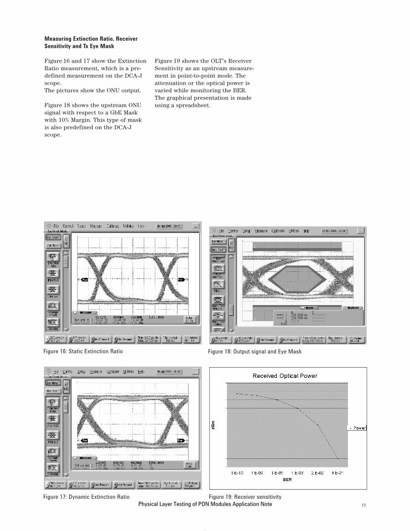
Figure 19 shows the OLT’s ReceiverSensitivity as an upstream measure-ment in point-to-point mode. Theattenuation or the optical power isvaried while monitoring the BER.The graphical presentation is madeusing a spreadsheet.
Measuring Extinction Ratio, ReceiverSensitivity and Tx Eye Mask
Figure 16 and 17 show the ExtinctionRatio measurement, which is a pre-defined measurement on the DCA-Jscope.The pictures show the ONU output.
Figure 18 shows the upstream ONUsignal with respect to a GbE Maskwith 10% Margin. This type of maskis also predefined on the DCA-Jscope.
ApplicationNote_PON 29.06.2005 16:38 Uhr Seite 11
Physical Layer Testing of PON Modules Application Note

12
Measuring Upstream Jitter
Figure 20 shows the setup of a electrical signal with jitter applied toONU1. The jitter modulation is ac-cording to the eye mask in figure 8.A sinusoidal signal from the functiongenerator is applied to the DelayControl of a ParBERT generator toclose the eye by 0.56 UI (an opening of448 ps). This can be controlled usingthe markers on the DCA-J scope.
Figure 21 shows the output ofONU1device when the signal fromfigure 20 is applied.The eye opening is further reducedby the intrinsic jitter of ONU1.
The standard requires measure-ments of both upstream and down-stream Tj and Dj. Upstream it isrequired with and without jitterapplied to the ONU.The Output Timing measurementprovided by the ParBERT mea-surement suite give direct readingsof the Tj and Dj measurements.
Figure 22 shows the measurementsobtained with and without jittermodulation. The graph visualizes theBER over time, the table belowallows a direct read-out of remainingEye Opening (Phase Margin), and thevalues of Dj and Tj. The Tj value isextrapolated for a BER of 1e-12 asspecified by the standard.
Figure 20: Jitter input signal
Figure 21: Output signal with jitter applied
Figure 22: Tj and Dj at OLT output
ApplicationNote_PON 29.06.2005 16:38 Uhr Seite 12
Physical Layer Testing of PON Modules Application Note

13
RX Stressed Eye, Dynamic Range & RX Sinusoidal Tolerance
Figure 23 shows the stressed eyesupplied to ONU1 for the vertical eyeclosure penalty test. By using powerdividers, a sinusoidal signal at 4 GHzis added to one of the differentialinputs to ONU1. The noise is incre-mented until the BER shows errors.At this point the ONU1 input signalis measured giving:
Vertical eye closure Penalty: 6.64dBAn = 800 mVAo = 173 mV
Figure 24 shows the DynamicBehavior against BER. The setupused is same as in Figure 15.
Figure 25 shows the Sinusoidal JitterTolerance.Jitter is added to the data sent toONU1 by applying a sinusoidal signalto the delay control input of theParBERT. The amplitude of the sinu-soidal signal sets the amount of jitter. It is increased until the BERshows errors. The current jitter modulation (Pj) is measured with theDCA-J scope. This is repeated fordifferent frequencies of the sinu-soidal signal. The graphical presen-tation is made using a spreadsheet.It shows the maximum Pj (in UI) tolerated as a function of jitter fre-quency.
Figure 23: Stressed Eye applied to ONU 1
Figure 24: Loud/Soft Range
Figure 25: Jitter Tolerance
ApplicationNote_PON 29.06.2005 16:38 Uhr Seite 13
Physical Layer Testing of PON Modules Application Note

14
Part 2: Optical Measurements
Both the ONU and OLT modules, andtheir subcomponents, such as di-plexers and triplexers, are character-ized in the optical wavelength andamplitude domains according tointernational standards. This assurespractical and optimized network use in the PON. The specified wave-length range used for upstream anddownstream transmission differs for various PON architectures.Generally, signal transmission is inthe ranges 1260-1360 nm (O-band)and 1480-1560 nm (S- and C-band).These are important for transmitterand receiver characterization2,3.
Testing RMS Spectral Width
Spectral characterization of thetransmitter laser assures operationin the specified wavelength rangeand within the specified spectralwidth. Transmitters for the accessnetwork mostly take advantage ofcost-effective laser sources, for whichspectral width could be a concern.Typically, the ONU uses Fabry-Perotlasers, which are economical andwell suited to O-band wavelengths.The limits for spectral width becometighter for both module types whenthe center wavelength of the laser isnot at the center of the band, sincethis increases dispersion penalty andthe bit error ratio.
Thanks to the generous wavelengthranges and moderate data rates, the spectral specifications for PONtransmitters do not need the mostexpensive laser technology. Thesecan be tested with an optical spec-trum analyzer (OSA). Its optimizedsweep time and portability providesthe best fit for both development and manufacturing when minimummeasurement time and adequateaccuracy and sensitivity are takeninto consideration.
Figure 26 shows spectra from aninexpensive DFB laser source in anOLT (left) and a Fabry-Perot lasersource in an ONU (right), both mea-sured with the Agilent 86143B OSA.
Special characterization needs to bedone for WDM-PON, because theservice provider and subscribers areconnected virtually point-to-pointusing individually dedicated wave-lengths. The advantages of this arenetwork expandability and lack ofsignal collision4. Mature WDM mea-surement technology provides theability to test such components withsingle-box test solutions that includea tunable laser source (TLS) withsub-picometer resolution and one ormore power meters to measure thespectra accurately.
Figure 26: Spectra from an inexpensive DFB laser source (left) and Fabry-Perot laser source (right)
Average Launch Power for theTransmitter
Absolute power measurement forONU and OLT transmitters can bemade using an optical power meter.The uncertainty of the meter deter-mines the accuracy of the test. Theresponsivity curve of InGaAs photo-diodes used in the Agilent 81634BOptical Power Sensor is optimizedfor O- to L-band detection and cali-brated for ± 2.5% uncertainty*. An uncertainty of ±1.5% is possibleusing the Agilent 81624B OpticalHead. When measuring high portcounts, the dual channel Agilent81635A Optical Power Sensor in-creases throughput, and minimizesthe cost of ownership and invest-ment.
*all uncertainties traceable to NISTand PTB standards laboratories.
ApplicationNote_PON 29.06.2005 16:38 Uhr Seite 14
Physical Layer Testing of PON Modules Application Note

15
Receiver Sensitivity and Reflectance
The receiver characteristics of primary interest are sensitivity andreflectance. The performance reli-ability of the signal conditioning unitin a test setup greatly influences any electrical and optical test param-eters. Signal conditioning includesoptical attenuators for controllingthe signal power level to determinesensitivity, and optical switches forautomating the setup for operationalefficiency. The challenge is to mini-mize measurement uncertainty inthe test setup. The result of ONUextinction ratio in the eye diagramusing the Agilent DCA-J scope isobserved to compare the influence ofusing an optical attenuator on thetest result. An experimental resultshows the difference between theextinction ratio without any attenu-ator in the test setup and withAgilent 81577A Optical Attenuator isonly 0.09dB.
Figure 27 compares the influence ofoptical attenuators in the test setup.(left: no attenuator, center: resultusing Agilent 81577A, right: resultusing other attenuator)
Optical attenuators, couplers, andpower meters are combined in thetest setup but the lack of specifica-tion for such multiple equipmentsetups can make performance unpre-dictable. Minimizing the complexity,and therefore such measurementuncertainty, can be achieved usingan optical attenuator with integratedpower control, such as the Agilent81576A or 81577A OpticalAttenuator. All the performanceincluding accuracy, insertion loss,and return loss are specified for the instrument, so the measurementuncertainty can be quantified andcalculated.
Figure 27: Comparison of the influence of optical attenuators
References
[1] The PON Forum: www.ponforum.org
[2] IEEE Draft P802.3ah™/D3.3(Amendment toIEEE Std 802.3™-2002)
[3] ITU-T G.983.x, G.984.xwww.itu.int/home/
[4] Journal of Lightwave Technology,vol. 22, No.11, November 2004
Considerations for NetworkMaintenance
After deployment it is suggested tomaintain the access network usingan optical signal, for example at1650 nm5, for active line monitoring.This is critical for regular networkmaintenance, or in TDMA when it isnecessary to perform an installationtest for new subscribers withoutincurring service down-time. Thecharacterization of components forthis is typically done with an OSA(often in combination with a TLS)that can measure to 1650 nm andabove. Optical time-domain reflec-tometry (OTDR) is commonly usedfor monitoring the deployed net-work.
[5] ITU-T L.53
[6] Byung-gu Ahn, Application Engineer AgilentTechnologies, KoreaMaster Degree in ElectronicEngineering, Kookmin University,2002
ApplicationNote_PON 29.06.2005 16:38 Uhr Seite 15
Physical Layer Testing of PON Modules Application Note

16
www.agilent.com
Agilent Technologies’ Test and Measurement Support, Services, and AssistanceAgilent Technologies aims to maximize the value you receive, while minimizing yourrisk and problems. We strive to ensure that you get the test and measurementcapabilities you paid for and obtain the support you need. Our extensive supportresources and services can help you choose the right Agilent products for yourapplications and apply them successfully. Every instrument and system we sell has a global warranty. Two concepts underlie Agilent’s overall support policy: “OurPromise” and “Your Advantage.”
Our PromiseOur Promise means your Agilent test and measurement equipment will meet its advertised performance and functionality. When you are choosing newequipment, we will help you with product information, including realistic perform-ance specifications and practical recommendations from experienced test engi-neers. When you receive your new Agilent equipment, we can help verify that itworks properly and help with initial product operation.
Your AdvantageYour Advantage means that Agilent offers a wide range of additional expert testand measurement services, which you can purchase according to your unique tech-nical and business needs. Solve problems efficiently and gain a competitive edge by contracting with us for calibration, extra-cost upgrades, out-of-warranty repairs,and onsite education and training, as well as design, system integration, projectmanagement, and other professional engineering services. Experienced Agilentengineers and technicians worldwide can help you maximize your productivity, opti-mize the return on investment of your Agilent instruments and systems, and obtaindependable measurement accuracy for the life of those products.
www.agilent.com/find/openAgilent Open simplifies the process of connecting and programming test systemsto help engineers design, validate and manufacture electronic products. Agilentoffers open connectivity for a broad range of system-ready instruments, openindustry software, PC-standard I/O and global support, which are combined tomore easily integrate test system development.
United States: Korea:(tel) 800 829 4444 (tel) (080) 769 0800(fax) 800 829 4433 (fax) (080)769 0900Canada: Latin America:(tel) 877 894 4414 (tel) (305) 269 7500(fax) 800 746 4866 Taiwan:China: (tel) 0800 047 866(tel) 800 810 0189 (fax) 0800 286 331(fax) 800 820 2816 Other Asia PacificEurope: Countries:(tel) 31 20 547 2111 (tel) (65) 6375 8100Japan: (fax) (65) 6755 0042(tel) (81) 426 56 7832 Email: [email protected](fax) (81) 426 56 7840 Contacts revised: 05/27/05
For more information on Agilent Technologies’ products, applications or services,please contact your local Agilent office. The complete list is available at:
www.agilent.com/find/contactus
Product specifications and descriptions in this document subject to change without notice.
© Agilent Technologies, Inc. 2005Printed in the Netherlands, June 30th, 20055989-3298EN
www.agilent.com/find/emailupdatesGet the latest information on the products and applications you select.
Agilent Email Updates
Related Literature Publication No.
Fast Total Jitter Test Solution 5989-3151ENApplication Note Next Generation I/O Bus 5989-2690ENPCI-Express BER Test SolutionApplication Note Agilent ParBERT 81250, 5968-9188EParellel Bit-Error-Rate TesterProduct Overview Jitter Tolerance Testing 5989- 0223ENAgilent ParBERT 81250 PlatformApplication Note
www.agilent.com/find/agilentdirectQuickly choose and use your test equipment solutions with confidence.
www.agilent.com/find/ParBERT
ApplicationNote_PON 29.06.2005 16:38 Uhr Seite 16