Embed Size (px)
Citation preview

Physical Origins of Extreme Cross-Polarization Extinction in Confocal Microscopy
Meryem Benelajla ,1,2 Elena Kammann,1 Bernhard Urbaszek ,2 and Khaled Karrai1,*1attocube systems AG, Eglfinger Weg2, 85540 Haar, Germany
2Universite de Toulouse, INSA-CNRS-UPS, LPCNO, Toulouse 31077, France
(Received 29 April 2020; revised 14 January 2021; accepted 15 February 2021; published 7 April 2021)
Confocal microscopy is an essential imaging tool for biological systems, solid-state physics andnanophotonics. Using confocal microscopes allows performing resonant fluorescence experiments, wherethe emitted light has the same wavelength as the excitation laser. These challenging experiments are carriedout under linear cross-polarization conditions, rejecting laser light from the detector. In this work, weuncover the physical mechanisms that are at the origin of the yet-unexplained high polarization rejectionratio which makes these measurements possible. We show in both experiment and theory that the use of areflecting surface (i.e., the beam splitter and mirrors) placed between the polarizer and analyzer incombination with a confocal arrangement explains the giant cross-polarization extinction ratio of 108 andbeyond. We map the modal transformation of the polarized optical Gaussian beam. We find an intensity“hole” in the reflected beam under cross-polarization conditions. We interpret this hole as a manifestationof the Imbert-Fedorov effect, which deviates the beam depending on its polarization helicity. This resultimplies that this topological effect is amplified here from the usually observed nanometer to the micrometerscale due to our cross-polarization dark-field methods. We confirm these experimental findings for a largevariety of commercially available mirrors and polarization components, allowing their practicalimplementation in many experiments.
DOI: 10.1103/PhysRevX.11.021007 Subject Areas: Nanophysics, Optics, Photonics
I. INTRODUCTION
In optical spectroscopy experiments, it is crucial to excitean emitter with a laser very close to its transition energy.Experiments under resonant excitation are essential foraccessing the intrinsic optical and spin-polarization proper-ties of a large class of emitters [1–5]. Resonance fluores-cence is not limited to quantum dots [6], which are known asrobust, fast, bright, and narrow-linewidth emitters of singlephotons [7,8]. It is also used to study novel solid-statematerial systems with longer coherence times suitable forquantum information storage, computation, and sensing at asingle-photon level [9–11] such as transition metal dichal-cogenide monolayers [12], rare earth elements [13], singlenitrogen vacancy [10], tin vacancy [14], silicon [15], andgermanium vacancy in diamond [16]. Using linear cross-polarization in a confocal setup has been successfullyemployed as a dark-field method to carry out resonantfluorescence experiments to suppress scattered laser light,with the added benefit of high spatial resolution [17,18].
Resonant fluorescence experiments allow crucial insightsinto light-matter coupling, such as the interaction of a single-photon emitter with its environment [19], with opticalcavities [20], and also studying single defects in atomicallythin materials such as WSe2 [12]. Dark-field confocaltechniques allow developing single-photon sources withhigh degrees of photon indistinguishability [21–23] andlonger coherence [24]. In practice, dark-field laser suppres-sion is not just a spectroscopy tool; it is also a key part ofmore matured quantum technology systems [25].Resonant excitation is absolutely necessary for manipu-
lating quantum states or for any operation that relies on phasecoherence. A striking example is the realization and verifi-cation of quantum entanglement between an NV electronspin qubit and a telecom-band photonic qubit [26]. Here,readout via a phonon sideband is impossible, as phononemission implies that the target states are no longerentangled. The dark-field approach is adopted for enablingpracticable quantum networks using quantum dots [20,27]and diamond defects [9,11,28] embedded in optical cavities.Despite many advances based on experiments in confocal
microscopes with cross-polarization laser rejection, thephysical mechanisms that make these experiments possibleare not well understood, hampering further progress in thisfield. The key figure of merit is the suppression ofthe excitation laser background by at least 6 orders ofmagnitude. Pioneering work by Wilson et al. shows that
Published by the American Physical Society under the terms ofthe Creative Commons Attribution 4.0 International license.Further distribution of this work must maintain attribution tothe author(s) and the published article’s title, journal citation,and DOI.
PHYSICAL REVIEW X 11, 021007 (2021)
2160-3308=21=11(2)=021007(13) 021007-1 Published by the American Physical Society

cross-polarization extinction of a confocal microscope ismuch higher than of a classical microscope and that it couldreach, but never exceed, the polarizer intrinsic extinctionlimitation, which in their case is 104 [29] to 105 [30]. Thisresult is very different from our findings, in which wedemonstrate how to go beyond the intrinsic polarizerextinction limit by 3–4 orders of magnitude. Indeed, asuppression by a factor of 108 [31] up to 1010 (this work)have beenmeasured. But this result is very surprising, as notonly real polarizer extinction limitation but also the lenses,mirrors, and beam splitter in such a system reduce thetheoretical extinction limit to the 103–104 range.In this work, we explain the physics behind the giant
enhancement of the extinction ratio by up to 7 orders ofmagnitude that make microscopy based on dark-field lasersuppression possible. The measurements of resonant fluo-rescence are typically performed in an epifluorescencegeometry [31], for which laser excitation and fluorescencecollection are obtained through the same focusing lens.This measurement involves necessarily the use of a beamsplitter orienting the backreflected light containing thefluorescence toward a detection channel. In our work,we identify two key ingredients that explain the giantamplification of the cross-polarization extinction ratio: (i) areflecting surface (i.e., the beam splitter) placed between apolarizer and analyzer and (ii) a confocal arrangement. Wedemonstrate giant extinction ratios in our experiments fordifferent mirrors (silver, gold, dielectric, and beam-splittercubes) and polarizers (Glan-Taylor and nanoparticle thinfilms). We demonstrate that behind this general observationlies the intriguing physics of the Imbert-Fedorov effect[32,33], which deviates a reflected light beam depending onits polarization helicity. We discover that a confocalarrangement amplifies the visibility of the Imbert-Fedorov effect dramatically, taking it from the nanometerto the micrometer scale. As a result of this micrometer shift,the cross-polarized laser beam is not coupled into thedetection fiber, explaining the near-complete suppressionof the laser background signal. In other words, we cannottreat the spatial and polarization properties of light sepa-rately in our dark-field confocal microscope analysis. Inaddition to new developments in dark-field microscopy, ourexperiments provide powerful tools for research in topo-logical photonics [34–36], in the broader context of what istermed the spin-Hall effect of light [36].In our work, we setup a robust, reproducible experiment
and derive a formalism to investigate these remarkableeffects at the crossroads of quantum optics and topologicalphotonics.The paper is structured as follows. In Sec. II, we
introduce the experimental setup. Cancellation of polari-zation leakage is measured and discussed in a firstsimplified model in Sec. III. The modal transformationof a reflected Gaussian beam is analyzed in Sec. IV. Theeffect of confocal filtering is discussed in Sec. V.
II. CONFOCAL MICROSCOPE SETUP
We use a simplified confocal arrangement as depicted inFigs. 1(a) and 1(b) in order to focus on the most relevantphysics leading to extreme laser rejection. A diode laserbeam (1) at λ ¼ 905 nm wavelength is launched into asingle-mode fiber (2). The light emerges from the 4° angledflat-polished end with a nearly perfect Gaussian beam withω0 ¼ 2.5 μm mode waist radius at 1=e2 of the maximumintensity. A diffraction-limited microscope objective (3) ofnumerical aperture NA ¼ 0.25 and focal length of f ¼26 mm focused on the fiber end collimates the light into a3-mm-waist-radius Gaussian beam. We choose the NA tobe significantly larger than the diverging beam half-angleout of the fiber in order to preserve the Gaussian quality ofthe beam.A pair of mirrors (4 and 5) mounted on two axis tilt
stages allows for fine steering of the collimated beam axis.Next, the beam travels to a linear polarizer (6) mounted on apiezoelectric stepping stage rotating with 20 μrad resolu-tion around the optical axis. The best-quality commerciallinear polarizers we use for this experiment show anextinction in direct cross-polarization limited to 105 for ananoparticle thin film polarizer and to 106 for Glan-Thomson crystal polarizers. The beam travels then towarda mirror (8), the key element of this experiment, either bypassing first through an analyzing polarizer [Fig. 1(a)] forthe control measurement or by passing through the analyzerafter a reflecting surface for the test experiment [Fig. 1(b)].We mount the analyzer also on a piezo stepper fine rotationstage. The mirror (9) mounted on the two-axis piezocontrolled tilt stage steers the beam into a microscopeobjective (10) identical to (3) focusing the light into thecore of a single-mode fiber (11) identical to (2) allowingfor Gaussian TEM00 modal confocal filtering and opticaldetection [(12)-Si-photodiode] at the other end of the5-m fiber cable. This confocal arrangement simulates theessential components of the resonant fluorescence confocalmicroscopes. The reflecting surface plane (8) at 45° ofincidence defines the standard p and s states of polarizationwith projections along ex and ey, respectively. The reflect-ing test surfaces in position (8) in Figs. 1(a) and 1(b) we usein this work are commercial protected silver, aluminum,and dielectric high-reflectivity Bragg mirrors and evapo-rated gold film, as well as nonpolarizing beam-splittercubes. All such reflecting surfaces are typically used indiffraction-limited confocal microscopes. The results arequalitatively very similar for all these reflecting surfaces.We choose to show here the data measured with silvermirrors only, with the exception of data measured forcomparison on a glass surface reflecting from air asdiscussed at the end of this publication.We now discuss the measurements in the configuration
shown in Fig. 1(b), for which the reflecting test surface issandwiched between the polarizer and the analyzer. First,
BENELAJLA, KAMMANN, URBASZEK, and KARRAI PHYS. REV. X 11, 021007 (2021)
021007-2

the polarizer angle β is adjusted near 0 or π=2, for p or spolarization, respectively, while setting the analyzer angle αnear cross-polarization at β � π=2. Then, the polarizer andanalyzer are subsequently finely rotated to reach maximumextinction at values β and α, respectively. Once theoptimization is reached, β remains untouched and theanalyzer in its rotator is subsequently placed beforethe reflecting surface just after the polarizer for our controlextinction measurement [Fig. 1(a)]. The analyzer anglemust then be adjusted to a new value α0 in order to recovermaximum nominal extinction specification inherent to thepolarizers; α0 defines then the p or s reference. Theextinction data measured as a function of the analyzerangle α in reference to α0 are shown in Fig. 1(c) for thecontrol measurement [Fig. 1(a)] as well as for the p and spolarizations in the configuration [Fig. 1(b)]. Two strikingobservations stand out. (i) For all the tested reflectorsindicated above, the extinction ratio obtained this way isenhanced beyond the 108 range when the test mirror surfaceis sandwiched between the polarizer and the analyzer,reducing this way significantly the polarization leakageof the polarizers. (ii) The analyzer angle for maximumextinction is shifted away from α0 by þ0.898° and −0.977°for the p and s polarization, respectively, a significantangular deviation given our resolution of about 10−3 deg.In the next section, we provide a first explanation for thesetwo striking observations.
III. CANCELLATION OFPOLARIZATION LEAKAGE
Intuitively, the significant reduction of the polarizationleakage field must find its root in a destructive interferenceeffect. The first challenge toward finding an answer to ourproblem is to offer a model of the polarization leakage. Inorder to determine the light field at various planes such asafter the polarizers and mirrors, we define a right-handcoordinate system p, s transverse to the optical beampropagation axis p × s according to the definition of p ands polarization with respect to the plane of incidence withthe test surface (8) in Fig. 1(b). For clarity, s≡ ey isperpendicular to the incidence plane. In this section, we testfirst the simplistic idea that the collimated laser beam canbe approximated by a plane wave. We use a Jones matricesformalism projecting the field components along p, s aftereach relevant optical element, namely, the matrix ¯PðβÞ ofthe polarizer, ¯M of the reflecting test surface, and ¯AðαÞ thatof the analyzer. In this formalism, an ideal linear polarizeralong p and s is represented by
¯Pp0¼
�1 0
0 0
�; ¯Ps0 ¼
�0 0
0 1
�: ð1Þ
We assume now that a real physical linear polarizeralong p or s represented by ¯Pp ¼ ¯L ¯Pp0
and ¯Ps ¼ ¯L ¯Ps0 ,
FIG. 1. (a),(b) Cross-polarization extinction setup in a confocal microscope arrangement setup as described in the text. (c) Measuredand modeled linear polarization extinction ratio for both p- and s-polarized beams around cross-polarization conditions obtained byplacing the analyzer before (a) and after (b) a protected silver mirror. A giant extinction enhancement of more than 3 orders of magnitudeis obtained in configurations s and p with the reflecting surface placed between crossed polarizers. The inset is a magnification of thepolarization extinction near maximum for the s polarization. An angular shift of the location of maxima of extinction is systematicallyfound for the s and p polarization with respect to the reference. When the linear polarization is tilted at�45° from the plane of incidence,the extinction reduces dramatically down to about 41 as shown with the lowest curve and data point.
PHYSICAL ORIGINS OF EXTREME CROSS-POLARIZATION … PHYS. REV. X 11, 021007 (2021)
021007-3

respectively, and is characterized by a polarizer leakageJones matrix ¯L. The assumption we are making about thephysical origin of the leakage is that it is due to losslesscoherent scattering such as Rayleigh scattering inclusionsin the crystal. This assumption, which we verify exper-imentally, is that the leakage should be invariant upon anarbitrary angular rotation φ around the optical axis p × s,namely, ¯L ¼ ¯RðφÞ ¯L ¯Rð−φÞ, where the rotation matrix¯RðφÞ is given by
¯RðφÞ ¼�cosφ − sinφ
sinφ cosφ
�: ð2Þ
We choose to represent the polarization leakage by a matrixgenerating a residual elliptical polarization:
¯L ¼�a −ibib a
�; ð3Þ
where a2 þ b2 ¼ 1. Such a form is invariant upon rotation.For a high-quality commercially available linear polarizer,a2 ≫ b2, which is the case in our setup, since from ourexperiment we determine a2=b2 ≅ ð1.5� 0.5Þ × 105. Thisresult is the measured nominal leakage seen in Fig. 1(c). Wenote that the formalism can also be extended to circularpolarizers, in which case a2 ≅ b2 and the leakage stemsfrom the slight difference between the two terms.We assume an incoming laser field Ep initially p
polarized that we rotate at an angle β, aligning it withthe polarizer such EðβÞ ¼ ¯RðβÞEp. This field first traverses
the leaky polarizer also rotated at β such that ¯PðβÞ ¼¯RðβÞ ¯L ¯Pp0
¯Rð−βÞ followed by the mirror matrix ¯M andby the analyzer matrix rotated at an angle α, namely,¯AðαÞ ¼ ¯RðαÞ ¯L ¯Ap0
¯Rð−αÞ, so the field E just after theanalyzer is written
E ¼ ¯AðαÞ ¯M ¯PðβÞ ¯RðβÞEp: ð4Þ
The mirror Jones matrix for a plane wave is written
¯M ¼�rp 0
0 rs
�; ð5Þ
where rp;s are the complex-valued Fresnel reflectivity coef-
ficients rp¼ðϵcosθi−ffiffiffiffiffiffiffiffiffiffiffiffiffiffiffiffiffiffiϵ−sin2θi
pÞ=ðϵcosθiþ
ffiffiffiffiffiffiffiffiffiffiffiffiffiffiffiffiffiffiϵ−sin2θi
pÞ
and rs ¼ ðcos θi −ffiffiffiffiffiffiffiffiffiffiffiffiffiffiffiffiffiffiffiffiϵ − sin2 θi
pÞ=ðcos θi þ
ffiffiffiffiffiffiffiffiffiffiffiffiffiffiffiffiffiffiffiffiϵ − sin2 θi
pÞ
[37], where the test surface material enters through itscomplex-valued effective dielectric function ϵ ¼ n2=ϵbackor, equivalently, its optical constant n2 ¼ ϵ1 þ iϵ2, whichis tabulated for noble mirror metals [38]. Here, ϵback is thedielectric function of the medium covering the mirror. Silverandaluminummirrors are often coveredwith about 100nmof
SiO2 protective layer. After a lengthy but straightforwardcalculation, we determine the light intensity just after theanalyzer:
I ¼ a2jrp cosα cos β þ rs sinα sin βj2þ b2jrp cos α sin β − rs sin α cos βj2þ 2abImðrpr�sÞ cosα sinα: ð6Þ
The polarization extinction ratio is then simply given by 1=I.A practical check for pðsÞ polarized light, namely, forβ ¼ 0ðπ=2Þ and the corresponding cross-polarizationα ¼ π=2ð0Þ leads to the expected finite polarization leakageI ¼ b2jrp=sj2. For a hypothetical perfect mirror, rp ¼ 1 andrs ¼ −1, making it in this idealized case I ¼ b2. Because thereflecting surface has real and imaginary components for rsand rp, Eq. (6) shows that for a ”sufficiently small value”ofb2
we can always find a unique choice of angles α and β thatleads to I ¼ 0, canceling thisway the undesired leakage. Thisresult is always true under condition of total internalreflection, which is the case of a metallic mirror in the visibleand infrared range and for a typical cube beam splitter.A sufficiently small value of depolarization to obtain perfectcancellation means in the context of our work typicallyb2 < 6 × 10⁻³when using a silvermirror aswe derive later inthe text. The reflecting test surface in combination with thepolarizer rotation acts to interfere destructively with theresidual rotation-invariant lossless polarization leakage inher-ent to even the best commercial linear polarizers. Conversely,for a purely dielectric surface such as glass (i.e., BK7)reflecting from the air side, for which rp and rs are bothreal, no full polarization leakage cancellation is possible. Forcomparison, we also test our model with a purely dielectricBK7 glass surface with reflectivity from the air side nearcross-polarization for the p polarization. The results areshown in Fig. 5(c). In this configuration, as expected from themodel, indeed there is no shift α − α0 between the conditionof maximum cross-polarization for the dielectric and thereference measurement. As expected, there is no effect ofcancellation of the polarization leakage. Here, the improvedpolarization from 105 to 106 seems to come only from thefact that in p polarization at 45° the glass surface has apolarizing effect.To get a better feel for the relevant parameters at work
in cancelling almost perfectly the polarization leakage, weuse the convenient complex form rp ¼ ρp expðiφpÞ andrs ¼ ρs expðiφsÞ. Consider high-reflectivity mirrors forwhich ρp ≈ ρs ≈ 1. Solving Eq. (4) for field cancellationleads to the first order in jbj ≪ 1 to a set of two equationscosðα − βÞ ¼ −ðb=aÞ tanΔ sinðαþ βÞ and cosðαþ βÞ ¼−ðb=aÞ cotΔ sinðα − βÞ, where Δ ¼ ðφp − φsÞ=2. Thisway, both α and β can be analytically calculated. In theparticular case of dielectrics reflecting from the air side forwhich Δ ¼ π=2, we see already that there are no solutions.Instead, we need the condition Δ ≠ π=2, which is always
BENELAJLA, KAMMANN, URBASZEK, and KARRAI PHYS. REV. X 11, 021007 (2021)
021007-4

verified in condition of total internal reflection. Forpure silver at λ ¼ 905 nm, φp − φs ¼ 192.52°, implyingtanΔ ¼ −9.12, which, in turn, shows that for this particularcase a solution I ¼ 0 exists for polarizers with leakagelevels b2 < 0.012. One more step is required to make use ofthese equations toward interpreting our results, because wedo not find any easy way to measure independently anabsolute value α and β to the precision required for ourmeasurements. As explained in the previous section, thevalue we can measure experimentally with the requiredaccuracy is only the shift α − α0. In the reference meas-urement with the analyzer placed directly after the polar-izer, we assume that the cross-polarization conditionα0 − β ¼ π=2 holds. For the test experiment, the equationcosðα − βÞ ¼ −b tanΔ is developed in the limit of smallleakage jbtanΔj≪1, so that we get α − β ¼ π=2� b tanΔfor the near p and s conditions, respectively. This resultshows that the correction to the analyzer is simplyα − α0 ¼ �b tanΔ, corresponding to α − α0 ¼ þ0.898°with a measured leakage 1=b2 ¼ 8.3 × 10⁴ and −0.977°with 1=b2 ¼ 9.6 × 10⁴ for the p and s state, respectively, inthe case of the measurement in Fig. 1(b), for a protectedsilver mirror. Given the measured leakage limiting thenominal extinction at 1=b2 ¼ ð1.5� 0.5Þ × 105, we deter-mine b ¼ −ð2.7� 0.5Þ × 10−3, which, in turn, allowsdetermining Δ ¼ 99.7°� 1.7°, a value to be compared tothe value for pure silver of Δ ¼ 96.27° [38]. We perform anindependent measurement of Δ and find Δ ¼ 98.3°, whichis consistent with our present measurement. Such a valueindicates that for our mirror the measured effectiveϵ1 ¼ −23 instead of −41 for pure silver. This importantdifference is due to the protective SiO2 layer of about 100 nmdeposited on the silver mirror we use. This simple novelmethod shows that we can conveniently measure the phaseshift φp − φs between p and s polarization after reflectionfor metals. For a metallic mirror, the phase tanΔ is, in fact,related to the angle of incidence θi, the negative real part ofthemetal dielectric function ϵ1, and the dielectric function ofthe protective layer ϵback through the following equation:tanΔ ≅ −
ffiffiffiffiffiffiffiffiffiffiffiffiffiffiffiffiffiffiffiffiffiffiffiffiffiffiffiffiffiffiffiffiffiffiffiffiffi−ϵ1=ϵback þ sin2 θi
p=ðsin θi tan θiÞ.
Our measurements performed using a high-reflectivityBragg mirror show larger shifts α − α0 ¼∓ 2.2° leadingto a phase shift φp − φs ¼ 189.2° between the p- ands-reflected components.The full measurements shown in Fig. 1(c) are fitted using
Eq. (6), accounting convincingly for the cross-polarizationextinction amplification and the slight polarizer andanalyzer rotation shift required to reach it. In the limitρs ≈ ρp, we calculate that the polarization leakage shouldbe sufficiently small to allow perfect extinction whenthe condition b2 < 1=(1þ tan2ðΔÞ) is verified. For ourexperimental case, this condition corresponds to b2 <2.1 × 10⁻² and for a pure silver to b2 < 1.19 × 10⁻².Such values are, in fact, relatively large and, thus, allow
realistically achieving polarization leakage cancellation formost standard commercial polarizers.A last practical aspect to address is the wavelength
dependency of this effect. For a highly reflecting mirror,the wavelength dependency is to be found in the phasedifference ΔðλÞ. As a result, the correction to the analyzerangle αðλÞ − α0 ¼ �b tanΔðλÞ calculated for reachingmaximum extinction is also a function of the wavelength.Hence, we see that the polarizer angle α of maximumextinction shifts as a function of wavelength as ∂α=∂λ ¼�bð∂Δ=∂λÞ= cos2 Δ, which can easily be evaluated usingthe formulas of the Fresnel coefficient and the correspond-ing dielectric constant of the mirror-relevant material. For aperfect silver mirror and a polarization leakage of 105, weevaluate a chromaticity rate of ∂α=∂λ ¼ 0.0019°=nm for awavelength around λ ¼ 905 nm. In this particular example,keeping the analyzer angle at a value of maximumextinction for 905 nm, the wavelength could be shiftedby up to �10 nm and still keep the extinction up to alevel > 107.At this point, we could conclude the paper here, as we
are able to explain convincingly all the features of theenhanced polarization extinction. Our analysis, however,misses so far a crucial point, namely, the experimental factthat the leakage cancellation was measurable only in aconfocal arrangement, a point that is elucidated in the nextsections. More specifically, the analysis we conduct leadingto the main result in Eq. (6) so far is done purely for a planewave for which the Jones matrix formalism is valid. Inreality, however, the finite size of the collimated Gaussianlaser beam imposes a finite angular wave distributionaround the angle of incidence on the mirror [39]. TheFresnel coefficient rp and rs becomes then a function of theangular distribution [39]. This function, as we see, leads tosignificant geometrical depolarization effects in the form ofnew optical modes limiting the total extinction to the 104
range. We see that a confocal arrangement filters away thedepolarization modes and that the result of this sectionturns out to be fortuitously usable.
IV. MODAL TRANSFORMATION OF AREFLECTED POLARIZED GAUSSIAN BEAM
To find the origin of the unexpectedly high polarizationrejection ratio >108, we map the detected intensity byscanning the spatial position of the collecting fiber in thefocal plane of the focusing objective.In the absence of a reflecting surface between the
analyzer and polarizer in cross-polarization, namely, thereference configuration in Fig. 1(a), the measurementsin Figs. 2(a) and 2(b) (upper row) show a pure TEM00
Gaussian mode field attenuated by 8.3 × 10⁴ and9.6 × 104 for a p- and s-polarized beam, respectively.This level is expected for the polarizer leakage specifica-tions. In contrast, when we place the analyzer after the
PHYSICAL ORIGINS OF EXTREME CROSS-POLARIZATION … PHYS. REV. X 11, 021007 (2021)
021007-5
reflecting test surface, the measurements show that themode splits into two lobes distributed along ey and locatedabove and below the reflectivity plane. In this cross-polarized configuration, we find an intensity “hole” atthe location of the optical fiber center. There, the intensityextinction is slightly higher than 108, a factor of 100 awayfrom our actual setup sensing limit. We occasionally reach1010 records in which the dark noise of the detector is, infact, the limiting factor. We experimentally verify thestability of this effect over tens of hours for p and slinearly polarized incident light. We observe qualitativelythe same effects for incidence angles of θi at 9°, 22°, 25°,30°, and 68°. We observe qualitatively the same behaviorfor different type of polarizers such as a crystal polarizer(Glan-Taylor) and nanoparticle thin film linear polarizers,for different mirrors such as silver, gold, aluminum,dielectric Bragg reflectors, and nonpolarizing beam-splittercubes, attesting to the robustness of this effect.To get a feel for the measured modal transformation
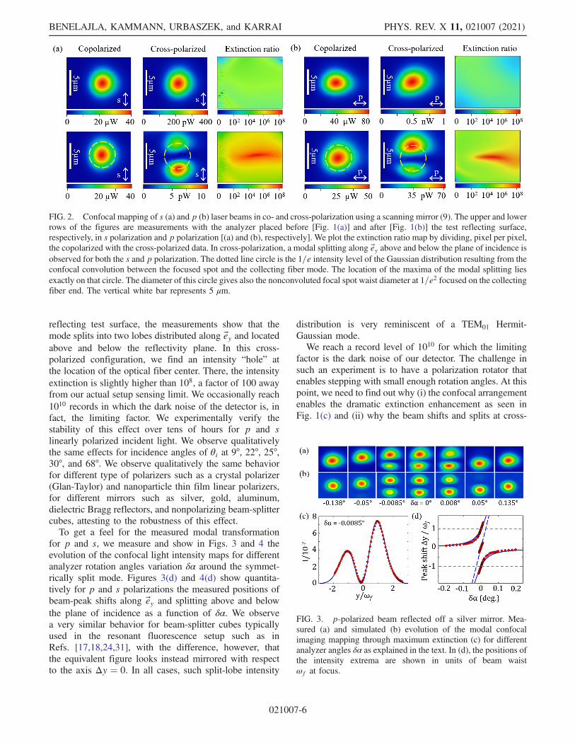
for p and s, we measure and show in Figs. 3 and 4 theevolution of the confocal light intensity maps for differentanalyzer rotation angles variation δα around the symmet-rically split mode. Figures 3(d) and 4(d) show quantita-tively for p and s polarizations the measured positions ofbeam-peak shifts along ey and splitting above and belowthe plane of incidence as a function of δα. We observea very similar behavior for beam-splitter cubes typicallyused in the resonant fluorescence setup such as inRefs. [17,18,24,31], with the difference, however, thatthe equivalent figure looks instead mirrored with respectto the axis Δy ¼ 0. In all cases, such split-lobe intensity
distribution is very reminiscent of a TEM01 Hermit-Gaussian mode.We reach a record level of 1010 for which the limiting
factor is the dark noise of our detector. The challenge insuch an experiment is to have a polarization rotator thatenables stepping with small enough rotation angles. At thispoint, we need to find out why (i) the confocal arrangementenables the dramatic extinction enhancement as seen inFig. 1(c) and (ii) why the beam shifts and splits at cross-
FIG. 2. Confocal mapping of s (a) and p (b) laser beams in co- and cross-polarization using a scanning mirror (9). The upper and lowerrows of the figures are measurements with the analyzer placed before [Fig. 1(a)] and after [Fig. 1(b)] the test reflecting surface,respectively, in s polarization and p polarization [(a) and (b), respectively]. We plot the extinction ratio map by dividing, pixel per pixel,the copolarized with the cross-polarized data. In cross-polarization, a modal splitting along ey above and below the plane of incidence isobserved for both the s and p polarization. The dotted line circle is the 1=e intensity level of the Gaussian distribution resulting from theconfocal convolution between the focused spot and the collecting fiber mode. The location of the maxima of the modal splitting liesexactly on that circle. The diameter of this circle gives also the nonconvoluted focal spot waist diameter at 1=e2 focused on the collectingfiber end. The vertical white bar represents 5 μm.
FIG. 3. p-polarized beam reflected off a silver mirror. Mea-sured (a) and simulated (b) evolution of the modal confocalimaging mapping through maximum extinction (c) for differentanalyzer angles δα as explained in the text. In (d), the positions ofthe intensity extrema are shown in units of beam waistωf at focus.
BENELAJLA, KAMMANN, URBASZEK, and KARRAI PHYS. REV. X 11, 021007 (2021)
021007-6

polarization in Fig. 2 (lower row) and always above andbelow the plane of incidence.To answer these questions, we need to first model the
spatial field Efx;y at the focal plane of the focusing lens justbefore the collecting single-mode optical fiber and then usethe collecting fiber as the confocal Gaussian filter functionporting the light to the detector. The finite-size beam beforethe mirror results from a Gaussian-weighted superpositionof plane waves propagating along an angular distributionk=k0 ¼ upþ vsþ wk0=k0 very narrowly centered aroundk0 the wave vector along the optical axis with k0 ¼ 2π=λ. Inthe paraxial approximation, u and v are both ≪1, so theyrepresent the angular spread of the collimated beam. The
focusing lens transforms each plane-wave component Eu;v
of the angular distribution into a field Efx;y in the focalplane; hence, the beam reaching the focal plane at distancef results from a coherent superposition of all such focusedcomponents. The spatial distribution of the field at a pointlocated at spatial coordinates ðp; s; zÞ after the mirror isgiven as
Eðp; s; zÞ ¼ZZþ∞
−∞
Eðkp; ks; kzÞeþikppþikssþikzzdkpdks: ð7Þ
The next step is to obtain the angular distribution Eu;v. Sucha problem is modeled for a Gaussian field distribution inRef. [40] by Aiello and Woerdman. We derive here asimplified version conveniently describing the essentialphysics needed to model our observations. We begin withthe field just before the polarizer, for which we assume alinearly polarized Gaussian-field normalized angular dis-
tribution E0u;v:
E0uv ¼ω20
4πE0 exp−
u2 þ v2
θ20
�cos β
sin β
�: ð8Þ
The mode divergence θ0 ¼ 2=ðk0ω0Þ ¼ ω0=l results fromthe finite size of the collimated laser beam with beamradius ω0 ≡ 3 mm, and the Rayleigh range l ¼ k0ω2
0=2 is31.24 m, a value much larger than the size of ourexperimental setup, allowing us to ignore the role of beampropagation up to the focusing lens. Here, the distancebetween the mirror of interest (8) and the focusing objectiveis typically 0.3 m. With this convention, a p- (s)- polarizedlight is obtained at β ¼ 0ðπ=2Þ. When the beam reflects offthe test surface, each plane-wave component acquires anangle-dependent Fresnel reflection coefficient rp;uv andrs;uv that are functions not only of θi but also of u and v[39]. Consequently, for each plane-wave component,we choose a coordinate system ep, es, k=k0 that definesa local incidence plane for that wave. The longitudinal basisvector is k=k0, and the transverse ones are es ¼ k=k0 × ezand ep ¼ ðk=k0 × ezÞ × ðk=k0Þ in the s and p planes,respectively. To obtain the reflectivity of the mirrorfor each plane wave, we determine first the weights ofp- and s-field components, given by the weighted projec-
tions rp;uvðep · E0uvÞ and rs;uvðes · E0uvÞ. We determinethen the resulting reflected field transverse field alongthe corresponding reflected basis es;R ¼ kR=k0 × ezand ep;R ¼ ðkR=k0 × ezÞ × ðkR=k0Þ such that Euv ¼rp;uvðep · E0uvÞep;R þ rs;uvðes · E0uvÞes;R. Here, kR is themirrored wave vector after reflection. In the paraxial limit,for a beam impinging, the Fresnel coefficients are devel-oped to the first order in u around θi and v around 0, givingrp;uv ¼ rp þ u∂rp=∂θi and rs;uv ¼ rs þ u∂rs=∂θi. Thefirst-order derivatives ∂rp=suv=∂v in the s plane vanishfor both rp and rs, leaving just derivatives r0p ¼ ∂rp=∂θiand r0s ¼ ∂rs=∂θi. We calculate the components of theincoming and reflected basis vectors ep, es, k=k0 and ep;R,
es;R, kR=k0 in the paraxial limit u; v ≪ θi. After a lengthybut straightforward calculation, we obtain the reflectedfield distribution after the mirror for each angle u, v. Weexpress the result conveniently in terms of matrix notationEuv ¼ ¯Mu;vE0uv, where
¯Mu;v ¼�rp 0
0 rs
�þ u
�r0p 0
0 r0s
�þ v
rp þ rstan θi
�0 −11 0
�:
ð9Þ
Upon inspection of the expression (9) for symmetries, wesee now that the reflectivity Jones matrix transforms animpinging perfect Gaussian mode, such as Eq. (8), into thesum of TEM00, TEM01, and TEM10 Hermit-Gauss modes.The indices for TEMnm indicate the number of nodes along
FIG. 4. s-polarized beam reflected off a silver mirror. Measured(a) and simulated (b) evolution of the modal confocal imagingmapping through maximum extinction (c) for different analyzerangles δα as explained in the text. In (d), the positions ofthe intensity extrema are shown in units of beam waist ωf
at focus.
PHYSICAL ORIGINS OF EXTREME CROSS-POLARIZATION … PHYS. REV. X 11, 021007 (2021)
021007-7

the p and s direction, respectively. The first term in theright-hand side is the normal test surface reflectivity we usein the first part of this paper. The second term is responsiblefor generating a TEM10 mode along p in the plane ofincidence. This term is, in fact, responsible for the Goos-Hänchen effect [41], as it has its physical origin in theangular dispersion of the reflectivity terms at θi. Here, thedifferent plane-wave components acquire slightly differentphases upon reflectivity shifting the beam in the plane ofincidence. Because this matrix is diagonal, we see that for aperfect p or s polarization the Goos-Hänchen effect doesnot contribute to depolarization.The third term, the mostrelevant to this work, is responsible for generating an out-of-plane-of-incidence TEM01 mode with two lobes alongey. This term is the physics responsible for the Imbert-Fedorov effect [32,33,36,42] known to deviate a reflectedlight beam above or below the plane of incidence depend-ing on its right-handed or left-handed polarization helicity.The calculation detailed above shows that this termoriginates purely from geometrical projections in whichthe gradual phase shift gained by each plane-wave com-ponent upon reflection sums to a cross-diagonal matrix thatmixes the p- and s-phase-shifted reflected plane-wavecomponents. Consequently, this term is responsible foran intrinsic reflectivity-induced depolarization for p and spolarization even when using ideally perfect polarizers.Because of the purely geometrical projection nature of theargumentation, compelling connections between theImbert-Fedorov effect, Berry’s phase, and spin-Hall effectof light are discussed in the literature [36,42]. Because ofthe direct proportional dependency of this matrix on theangle v and, in particular, its sign, it creates a TEM10 modeasymmetric along ey, adding (subtracting) the field to(from) the symmetric main mode, displacing this way itsweight above or below the plane of incidence depending onits helicity. This asymmetry can be easily verified using acircular polarization version of Eq. (8) with the Jonesmatrix equation (9). From this simple derivation, it is worthappreciating that in the paraxial approximation Eq. (9)expresses both Goos-Hänchen and Imbert-Fedorov effectsin an elegant and compact way. At this point, we can seefrom a symmetry argument that our confocal arrangementenhances cross-polarization extinction.In the following step, we express the field distribution
transmitted through the polarizer, the mirror, and analyzerat the back aperture of the focusing lens Euv ¼¯AðαÞ ¯Mu;v
¯PðβÞE0uv used in the Fourier transform equation(7). Before providing the general solution, we get first a feelfor the physical parameters governing the Imbert-Fedorovcross-polarized mode. We consider the special case ofa p- or s-polarized light impinging on the mirror andsubsequently analyzed in cross-polarization configuration.Here, only the third matrix on the rhs of Eq. (9) is relevant,and all other terms cancel.
The essential physical parameter that governs the Imbert-Fedorov mode field intensity is the sum rp þ rs given bythe material reflecting properties. To get a more physicalinsight, we use the representation rp ¼ ρp expðiφpÞ andrs ¼ ρs expðiφsÞ that can be conveniently symmetrizedusing ρs ¼ ρþ δρ=2 and ρp ¼ ρ − δρ=2 for the reflectivityand Δ ¼ ðφp − φsÞ=2 the phase difference. This way, weobtain
rp þ rs ¼ 2ρ cosΔþ iδρ sinΔ ð10Þ
to within a constant proportional phase term exp iðφp þφsÞ=2 identical for all modes of Eq. (9). We now see thatthe difference φp − φs governs the intensity and the phaseof the Imbert-Fedorov mode. For instance, in the case ofthe air side reflectivity off a perfect dielectric, we haveφp − φs ¼ π, and, hence, rp þ rs ¼ iδρ, so the Imbert-Fedorov mode field intensity is directly proportional to thepure differential reflectivity between the p and s waves.In contrast, for dielectrics under total internal reflectivityand for metals, we have δρ ≈ 0 and ρ ≈ 1 so thatrp þ rs ¼ 2 cosΔ. In this case, the strength of the depola-rizing mode is fully governed by the phase differenceφp − φs. We conclude that mapping the Imbert-Fedorovmode fields in a confocal microscopy setup provides adirect and sensitive access to the differential reflectivityamplitude and phases of a reflecting surface. To moveforward with our analysis on the more general case, weperform the Fourier optics transformation equation (7).The result is that the field image at the entrance of thelens for the test experiment with the mirror placed betweenthe polarizers is Eðp; s; zÞ ¼ ¯AðαÞ ¯Mp;s;z
¯PðβÞE0ðp; s; zÞ,where the effective reflectivity Jones matrix is given by
¯Mp;s;z ¼�rp 0
0 rs
�þ iplþ iz
�r0p 0
0 r0s
�
þ islþ iz
rp þ rstan θi
�0 −11 0
�: ð11Þ
The spatial distribution of the field Eðp; s; zÞ resultsfrom the Fourier transform of the unperturbed linearlypolarized laser field angular distribution of Eq. (8) into aspatial normalized distribution such that
E0ðp; s; zÞ ¼ eik0z exp−p2 þ s2
ω20ð1þ iz=lÞ
�cos β
sin β
�: ð12Þ
The resulting reflected field distribution arriving at thelens turns out to be the one discovered in a different contextin the insightful and pioneering work of Aiello andWoerdman [43]. In their work, the authors provide, withina paraxial approximation, a complete analytical solutionfor the field distribution of a single-mode Gaussian
BENELAJLA, KAMMANN, URBASZEK, and KARRAI PHYS. REV. X 11, 021007 (2021)
021007-8

beam reflected off a mirror. The next step is to perform thelens transformation to obtain the field in the focalplane x, y [44]:
Eðx; y; fÞ
¼ −ie2i½ðx2þy2Þ=ω0ωf �
πω0ωf
ZZþ∞
−∞
Eðp; s;fÞe−2i½ðxpþysÞ=ω0ωf �dpds;
ð13Þ
where the focused spot waist radius ωf ¼ λf=πω0 ≃2.5 μm is the fiber Gaussian mode size and lf ¼ k0ω2
f=2its corresponding Rayleigh range, in our case 21.7 μm. It isuseful to note that lfðω0=ωfÞ ¼ f. We calculate theresulting field spatial distribution in the focal plane:
Eðx; y; fÞ ¼�−iþ z
l
�eik0ze
i2ðx2þy2Þ
ω0ωf e− ðx2þy2Þ
ω2fð1þiz=lÞ
×ω0
ωf
�¯M0 þ
xf
¯MGH þ yf
¯MIF
�E0: ð14Þ
The last matrix term gives the cross-polarized field com-ponent which is an antisymmetric function of y with twolobes with opposite phase and maxima located at y ¼�ωf=
ffiffiffi2
pabove and below the plane of incidence. The
essential finding from our work is that the confocalarrangement transforms the collimated beam waist ω0
and Rayleigh length lþ iz of the Aiello and Woerdman[43] field distribution at the mirror plane, into ωf and if inour case. Aiello and Woerdman [43] show that it is thefinite size of the beam at the reflecting surface that isresponsible for the additional field terms that affect theinitial Gaussian mode. This result amounts to a sizableamplification of the weak mode intensity in proportion toω0=ωf. From our work, it is becoming now clear here that aconfocal arrangement provides a valuable advantage toexplore experimentally the cross-polarization geometrywith sufficient sensitivity and a very fine spatial resolution.In particular, high-extinction cross-polarization extinctionis kin to the “weak measurement procedure” of Aharonovet al. [45,46], which we extend here to a confocal arrange-ment enabling the added benefit of spatial resolution.Recent literature [36] provides an interpretation for thedepolarization as resulting from an effective spin-orbitinteraction of light occurring at the mirror surface mani-festing itself in the form of a spin-Hall effect of light [47].In this work, we restrict ourselves to a purely modalinterpretation and leave the discussion concerning spinorbit aside.
V. EFFECT OF CONFOCALSPATIAL FILTERING
The one final point we need to address to get a fullquantitative interpretation of our experiment is to addressthe effect of the confocal filter function of the collectingfiber. The single-mode fiber collects and ports the field tothe photodetector; it does this collection, however, byacting as a Gaussian spatial filter. For our symmetric setupshown in Fig. 1, we illuminate and collect light with asingle-mode fiber of identical mode size and with identicalcollimating and focusing lenses. The spatial filtering is aconvolution between the field at the focal plane and thefiber Gaussian mode amounting to an integrated fieldπω2
fED at location x0, y0 of the fiber with respect to theoptical axis. The power measured at the other end of thefiber is πω2
fϵ0cEDEþD. The results of the calculation for
the field are the following. First, we get the mapping of thereference field without the use of the polarizers and thereflecting surface as measured by the detector:
ED0;0 ¼�−iþ z
l
�ω0
ωfE0eik0z exp−γ
x20 þ y202ω2
f
�cos β
sin β
�;
ð15Þ
where γ ¼ ð1þ 2η2Þ=ð1þ iηÞ and η ¼ ωf=ω0 þ z=2l. Wenote that the beam waist at focus appears now to bebroadened by a factor of
ffiffiffi2
pwhen comparing with the
distribution of Eq. (13). Second, we find that the confocalfiltering by convolution with a Gaussian mode leads to amodified effective Jones matrix for the reflecting surfaceacting on the field as seen from the detector:
¯MDx0;y0 ¼�rp 0
0 rs
�þ x02ζ
�r0p 0
0 r0s
�þ y02ζ
rp þ rstanθi
�0 −11 0
�;
ð16Þ
where ζ ¼ fð1 − iηÞ is a complex-valued length that weuse as a fitting parameter when comparing our experimen-tal data. With the confocal filtering, the Goos-Hänchen andthe Imbert-Fedorov field terms (i.e., the second and thirdterms of the rhs in the equation) are halved when comparedto Eq. (14). The Jones matrix related to the polarizers andpolarization leakage remains unchanged. With this lastcorrection, we have now all the equations required in orderto simulate the modal transformation induced by a reflect-ing surface acting on a polarized Gaussian beam and forany arbitrary polarization and polarization leakage level.Finally, the full scanning confocal mapping of the detectedfield is given by the analytical form
EDðx0; y0Þ ¼ ¯AðαÞ ¯MDx0;y0¯PðβÞED0;0: ð17Þ
PHYSICAL ORIGINS OF EXTREME CROSS-POLARIZATION … PHYS. REV. X 11, 021007 (2021)
021007-9

The first important result we are getting from Eq. (17) andthe mirror matrix term in Eq. (16) is when the location ofthe fiber center and the focal spot axis coincide, namely, forx0 ¼ 0 and y0 ¼ 0. In this case, the result is the same asfound in the simplified plane wave analysis in Sec. III, andthe equation of polarization cancellation given in Eq. (6)holds fortuitously. This result is the case because thefiltering function of the confocal arrangement eliminatesthe higher depolarizing modes. Without the confocalfiltering, the normalized integrated total intensity incross-polarization detected in wide field imaging of thefocused point, or collected with a wide core multimodefiber, is estimated by summing the measured light inten-sity collected in the cross-polarization mode such asshown in Fig. 2 and normalizing to the integrated intensityin the copolarized configuration. This estimation givesfor our silver mirror a best extinction possible in therange of 106, namely, for the best case for which we areusing the polarization leakage compensation approachdescribed earlier.This result demonstrates the key role of the confocal
arrangement for the giant polarization extinction reached inthe state of the art resonance fluorescence measurements[17,18,24,31].The second significant result is illustrated, applying
Eq. (17) on a purely p- or s-polarized beam measured incross-polarization, by mapping the focused spot positionðx0; y0Þ across the single-mode fiber end. The result is anintensity map displaying two lobe maxima located at thefiber location at x0max ¼ 0 and y0max ¼ �ωf above andbelow the plane of incidence. This result is in qualitativeagreement with our measurements as seen in Fig. 2 forsilver. We confirm these findings for Bragg mirrors andthin-film-based beam-splitter cubes. The third significantresult is depicted in Figs. 3(d) and 4(d), showing theevolution near cross-polarization of the position of thereflected maxima of intensity as well as the location ofthe intensity node as a function of the analyzer angle. Here,the best fit to the data obtained with Eq. (17) imposes apurely imaginary value to ζ about i600 μm. Failure to usean imaginary value for ζ leads to a radically differentcalculated dependency of the intensity extrema near cross-polarization for Figs. 3(d) and 4(d). The predicted evolutionwould be instead the one seen in Fig. 5(d) for a dielectricilluminated from the air side. This result came as acomplete surprise to us, and we have no explanation forwhy we need to use a purely imaginary ζ to fit all our data.The other surprise, aside from the imaginary value aspect,is that the absolute value of ζ is about 40 times shorter thanthe focal length f that would be normally close to thetheoretical value of ζ to be normally used to interpret ourexperiment. We conduct a similar measurement on a BK7glass surface illuminated from air. The measured and fitdata are shown in Fig. 5(d). Here as well, the value of ζ toget the best fit requires a purely imaginary value consistent
with the value used for Figs. 3(d) and 4(d). Numerous othermeasurements performed in the circular polarization basisas well as in a linear polarization basis 45° tilted from p ands confirm the necessity to use an imaginary value for thelength parameter ζ, showing that our understanding is stillincomplete. We believe that we are still missing a fullquantitative understanding in the way the receiving fiberfilters non-Gaussian modes. The use of an imaginary valueof ζ maps closely the evolution of the mode transformationnear the cross-polarization condition for both normal andtotal internal reflection. In our experiment, the materialparameter of the high-reflectivity surface that governs mostof the effects we observe is the phase difference φp − φs. Inparticular, for high-reflectivity materials and total internalreflection, the intensity of the lobe maxima at cross-polarization is obtained from Eq. (16) at fiber locationðx0; y0Þ ¼ ð0;�ωfÞ:
jEDð0;�ωfÞ=ED0;0j2 ¼1
4e
jrp þ rsj2tan2θi
�ωf
ζ
�2
: ð18Þ
In particular, for high-reflectivity materials, from Eq. (11),we have jrp þ rsj2=4 ¼ cos2Δ. In our experiment, wedetermine earlier that for the protected silver surfaceΔ ¼ 100°, so using the value of 600 μm we fit for theabsolute value of ζ, and the lobe intensity should beabout 2 × 10⁻⁷, which is in the range of our measuredvalues. We measure typical lobe maxima in the range of0.3–1.4 × 10⁻⁶. For a direct comparison, we test ourmodel with a purely dielectric BK7 glass surface withreflectivity from the air side near cross-polarization for thep polarization. The results are shown in Fig. 5. In this
FIG. 5. Measured (a) and simulated (b) evolution of the modalmapping through maximum extinction for reflectivity from the airside off a glass surface (BK7) for p polarization. (c) Red symbols:extinction ratio for different analyzer angle α shifts as explainedin the text. Black symbols: reference measurement with theanalyzer placed just after the polarizers. The positions of theintensity extrema are shown in units of beam waist ωf at focus.
BENELAJLA, KAMMANN, URBASZEK, and KARRAI PHYS. REV. X 11, 021007 (2021)
021007-10

configuration, as expected from the model discussed inSec. III, indeed there is no shift α − α0 between thecondition of maximum cross-polarization for the dielectricand the reference measurement. As expected also fromSec. III, there is no effect of cancellation of the polarizationleakage. The most remarkable difference is the way themode splitting evolves upon rotation of the analyzer. Theabsence of imaginary terms in rp and rs is the reason forthis behavior. Here, we see not only the Imbert-Fedorovout-of-plane splitting at cross-polarization but also theappearance of the Goos-Hänchen mode showing a mixingthat bends the beam shape along the plane of incidence.Figure 5 shows, in particular, the evolution of the beamsplitting near the cross-polarization condition which iscompletely different from what is seen for metals suchas in Figs. 3(d) and 4(d). Because Imðrsr�pÞ ¼ 0 for thereflectivity from the air side of a dielectric, there is no termlinear in δα near cross-polarization conditions as also seenfrom the experiments. For a dielectric, an analyticalsolution for the location of the lobe intensity maxima forvery small analyzer rotation angle δα ≪ 1 near the cross-polarization condition shows the quadratic evolutionobserved in our measurement.As a final note, we believe that we are still missing a full
quantitative understanding in the way the receiving fiberfilters non-Gaussian modes. Indeed, the sensitivity of oursetup should have permitted us to detect the higher-termmodes TEM11 that have a symmetry xy. Such modesoriginate from the finite-sized waist of the Gaussian beam,making it naturally divergent [48]. In fact, we can use theexact formalism developed above to show that such termsoriginate also from geometrical projections around theoptical axis. This time, the projection is not involvingany reflecting surface but just the natural divergence of thebeam before the lens, leading to a gradual phase shiftgained by each plane-wave component, here again depola-rizing naturally the beam. Keeping in mind the convolutionimposed by the collecting fiber, we calculate that theexpected clove-shaped mode is peaking at the four loca-tions ðx0; y0Þ ¼ ð�ωf;�ωfÞ with an intensity given by
jEDð�ωf;�ωfÞ=ED0;0j2 ¼1
4e2
�ωf
2lf
�4
; ð19Þ
a result corroborated in Ref. [48] and in Ref. [39]. Usingthis expression for our experiment parameters, the modepeak intensity should be 3.8 × 10⁻⁷, a value that is wellwithin our sensitivity range. It is a puzzling fact that we donot observe any trace of this TEM11 signal. There is nodoubt, however, that this mode is present as measured inRef. [48]; this difference is why we believe that ourunderstanding of the way the optical fiber is filtering thesignal is not complete yet.
VI. CONCLUSIONS
In conclusion, we have exposed a systematic experi-mental method based on a confocal microscopy arrange-ment to obtain a giant enhancement in dark-field cross-polarization extinction and by up to 3 orders of magnitudeand possibly beyond. We found that the effect exploits thematerial properties of a surface or interface under acondition of total internal reflectivity, in particular. Ourwork provides a good starting point for further researchaiming to optimize the performance of the microscopeoptics in terms of polarization extinction. According to ourwork, future research should focus on the phase character-istics of reflecting surfaces (such as beam-splitter cubes andmirrors) to cancel depolarization effects instead of merelydeveloping strategies to make very sophisticated, incon-venient, and extremely expensive microscope objectives.Our approach is simple, and the high polarization rejectioncan be achieved for a targeted wavelength excitation and isbased only on polarization properties of light. This basismeans it has the potential to open up a broad spectrum ofinnovative opportunities for applications and new forms ofinterdisciplinary research including biology [49], plas-monics [50], and optoelectronics [51], where resonantconfocal microscopy starts to play an important role.Future developments in quantum optics based on novel
nanostructures demand an enhanced quantum coherence,for instance, quantum entanglement between electronicspin state and photons which can be achieved only usingresonant laser spectroscopy. Thus, an extreme cross-polari-zation extinction coefficient ð>108Þ is very much the key toguarantee the optical spin coherence property of singlephotons. The technique presented here addresses promisingquantum optical systems currently explored in a largevariety of materials for which Stokes-shifted readout ofa coherent few-level system is not possible or inconven-iently weak. This was the reason why semiconductorquantum dot research profited very much from this tech-nique and was immediately adapted to single-moleculecoherent spectroscopy [52]. In the future, resonance fluo-rescence could favor the use of fluorophores that have weakintersystem crossing rates. Such molecules are attractive fortheir much increased photostability but at the cost of amuch reduced Stokes shift. Wide-band-gap materials areinteresting not only for their deep-level impurities but alsofor their quantum confinement such as in GaN and similarsystems. Here, there is no Stokes shift to allow for thereadout of the fundamental level of the system. The samegoes also for quantum confined layered system such asWSe2 as also recently studied by resonance fluorescence bycross-polarization confocal microscopy [12].
ACKNOWLEDGMENTS
We thank R. Warburton, M. Kroner, L. Novotny, O.Krebs, and C. Schaefermeier for useful discussions. Part of
PHYSICAL ORIGINS OF EXTREME CROSS-POLARIZATION … PHYS. REV. X 11, 021007 (2021)
021007-11

this project has received funding from the EuropeanUnion’s Horizon 2020 research and innovation programunder the Marie Skłodowska-Curie Grant AgreementNo. 721394 ITN 4PHOTON.
[1] I. Aharonovich, D. Englund, and M. Toth, Solid-StateSingle-Photon Emitters, Nat. Photonics 10, 631 (2016).
[2] A. Högele, M. Kroner, C. Latta, M. Claassen, I. Carusotto,C. Bulutay, and A. Imamoglu, Dynamic Nuclear SpinPolarization in the Resonant Laser Excitation of an InGaAsQuantum Dot, Phys. Rev. Lett. 108, 197403 (2012).
[3] M. Paillard, X. Marie, P. Renucci, T. Amand, A. Jbeli, andJ. M. Gerard, Spin Relaxation Quenching in SemiconductorQuantum Dots, Phys. Rev. Lett. 86, 1634 (2001).
[4] A. Högele, S. Seidl, M. Kroner, K. Karrai, R. J. Warburton,B. D. Gerardot, and P. M. Petroff, Voltage-ControlledOptics of a Quantum Dot, Phys. Rev. Lett. 93, 217401(2004).
[5] M. Atatüre et al.,Quantum-Dot Spin-State Preparation withNear-Unity Fidelity, Science 312, 551 (2006).
[6] Y. Arakawa and M. J. Holmes, Progress in Quantum-DotSingle Photon Sources for Quantum Information Technol-ogies: A Broad Spectrum Overview, Appl. Phys. Rev. 7,021309 (2020).
[7] N. Somaschi et al., Near-Optimal Single-Photon Sources inthe Solid State, Nat. Photonics 10, 340 (2016).
[8] L. Schweickert et al., On-Demand Generation ofBackground-Free Single Photons from a Solid-StateSource, Appl. Phys. Lett. 112, 093106 (2018).
[9] L. Childress and R. Hanson, Diamond NV Centers forQuantum Computing and Quantum Networks, MRS Bull.38, 134 (2013).
[10] L. Robledo, L. Childress, H. Bernien, B. Hensen, P. F. A.Alkemade, and R. Hanson, High-Fidelity Projective Read-Out of a Solid-State Spin Quantum Register, Nature(London) 477, 574 (2011).
[11] R. Vasconcelos, S. Reisenbauer, C. Salter, G. Wachter, D.Wirtitsch, J. Schmiedmayer, P. Walther, and M. Trupke,Scalable Spin-Photon Entanglement by Time-to-PolarizationConversion, npj Quantum Inf. 6, 9 (2020).
[12] S. Kumar, M. Brotóns-Gisbert, R. Al-Khuzheyri, A. Branny,G. Ballesteros-Garcia, J. F. Sánchez-Royo, and B. D.Gerardot, Resonant Laser Spectroscopy of LocalizedExcitons in Monolayer WSe 2, Optica 3, 882 (2016).
[13] P. Siyushev et al., Coherent Properties of Single Rare-EarthSpin Qubits, Nat. Commun. 5, 3895 (2014).
[14] M. E. Trusheim et al., Transform-Limited Photons from aCoherent Tin-Vacancy Spin in Diamond, Phys. Rev. Lett.124, 023602 (2020).
[15] T. Müller, C. Hepp, B. Pingault, E. Neu, S. Gsell, M.Schreck, H. Sternschulte, D. Steinmüller-Nethl, C. Becher,and M. Atatüre, Optical Signatures of Silicon-VacancySpins in Diamond, Nat. Commun. 5, 3328 (2014).
[16] D. Chen, Z. Mu, Yu. Zhou, J. E. Fröch, A. Rasmit, C.Diederichs, N. Zheludev, I. Aharonovich, and W.-b. Gao,Optical Switching of Resonance Fluorescence from a SingleGermanium Vacancy Color Center in Diamond, Phys. Rev.Lett. 123, 033602 (2019).
[17] A. N. Vamivakas, Y. Zhao, C.-Y. Lu, and M. Atatüre, Spin-Resolved Quantum-Dot Resonance Fluorescence, Nat.Phys. 5, 198 (2009).
[18] T. Kaldewey, A. V. Kuhlmann, S. R. Valentin, A. Ludwig,A. D. Wieck, and R. J. Warburton, Far-Field Nanoscopy ona Semiconductor Quantum Dot via a Rapid-Adiabatic-Passage-Based Switch, Nat. Photonics 12, 68 (2018).
[19] H.-S. Nguyen, G. Sallen, C. Voisin, Ph. Roussignol, C.Diederichs, and G. Cassabois,Ultra-coherent Single PhotonSource, Appl. Phys. Lett. 99, 261904 (2011).
[20] D. Najer et al., A Gated Quantum Dot Strongly Coupledto an Optical Microcavity, Nature (London) 575, 622 (2019).
[21] A. K. Nowak, S. L. Portalupi, V. Giesz, O. Gazzano, C.Dal Savio, P.-F. Braun, K. Karrai, C. Arnold, L. Lanco, I.Sagnes, A. Lemaître, and P. Senellart, Deterministic andElectrically Tunable Bright Single-Photon Source, Nat.Commun. 5, 3240 (2014).
[22] M. Müller, S. Bounouar, K. D. Jöns, M. Glässl, and P.Michler, On-Demand Generation of IndistinguishablePolarization-Entangled Photon Pairs, Nat. Photonics 8,224 (2014).
[23] E. Schöll et al., Resonance Fluorescence of GaAs QuantumDots with Near-Unity Photon Indistinguishability, NanoLett. 19, 2404 (2019).
[24] A. V. Kuhlmann, J. Houel, A. Ludwig, L. Greuter, D.Reuter, A. D. Wieck, M. Poggio, and R. J. Warburton,Charge Noise and Spin Noise in a Semiconductor QuantumDevice, Nat. Phys. 9, 570 (2013).
[25] H. Ollivier et al., Reproducibility of High-PerformanceQuantum Dot Single-Photon Sources, ACS Photonics 7,1050 (2020).
[26] A. Tchebotareva et al., Entanglement between a DiamondSpin Qubit and a Photonic Time-Bin Qubit at TelecomWavelength, Phys. Rev. Lett. 123, 063601 (2019).
[27] N. Tomm et al., A Bright and Fast Source of CoherentSingle Photons, arXiv:2007.12654 [Nat. Nanotechnol. (tobe published)], https://www.nature.com/articles/s41565-020-00831-x.
[28] R. H. Jensen et al., Cavity-Enhanced Photon Emissionfrom a Single Germanium-Vacancy Center in a DiamondMembrane, Phys. Rev. Applied 13, 064016 (2020).
[29] T. Wilson and R. Juškaitis, On the Extinction Coefficient inConfocal Polarization Microscopy, J. Microscopy 179, 238(1995).
[30] P. Higdon, R. Juškaitis, and T. Wilson, The Effect ofDetector Size on the Extinction Coefficient in ConfocalPolarization Microscopes, J. Microscopy 187, 8 (1997).
[31] A. V. Kuhlmann et al., A Dark-Field Microscope forBackground-Free Detection of Resonance Fluorescencefrom Single Semiconductor Quantum Dots Operating ina Set-and-Forget Mode, Rev. Sci. Instrum. 84, 073905(2013).
[32] F. I. Fedorov, On the Theory of Total Reflection, Dokl.Akad. Nauk SSSR 105, 465 (1955).
[33] C. Imbert, Calculation and Experimental Proof of theTransverse Shift Induced by Total Internal Reflection ofa Circularly Polarized Light Beam, Phys. Rev. D 5, 787(1972).
[34] T. Ozawa et al., Topological Photonics, Rev. Mod. Phys. 91,015006 (2019).
BENELAJLA, KAMMANN, URBASZEK, and KARRAI PHYS. REV. X 11, 021007 (2021)
021007-12

[35] V. S. Liberman and B. Y. Zel’dovich, Spin Orbit Interactionof a Photon in an Inhomogeneous Medium, Phys. Rev. A 46,5199 (1992).
[36] K. Y. Bliokh, F. J. Rodríguez-Fortuño, F. Nori, and A. V.Zayats, Spin-Orbit Interactions of Light, Nat. Photonics 9,796 (2015).
[37] F. Stern, Elementary Theory of the Optical Properties ofSolids, in Solid State Physics (Elsevier, New York, 1963),Vol. 15, pp. 299–408.
[38] P. B. Johnson and R.-W. Christy, Optical Constants of theNoble Metals, Phys. Rev. B 6, 4370 (1972).
[39] L. Novotny and B. Hecht, Principles of Nano-Optics(Cambridge University Press, Cambridge, England, 2012).
[40] A. Aiello and H. Woerdman, The Reflection of a Maxwell-Gaussian Beam by a Planar Surface, arXiv:0710.1643.
[41] F. Goos and H. Hänchen, Ein Neuer und Fundamentalerversuch zur Totalreflexion, Ann. Phys. (Berlin) 436, 333(1947).
[42] M. Onoda, S. Murakami, and N. Nagaosa, Hall Effect ofLight, Phys. Rev. Lett. 93, 083901 (2004).
[43] A. Aiello and J. Woerdman, Role of Beam Propagation inGoos-Hänchen and Imbert-Fedorov Shifts, Opt. Lett. 33,1437 (2008).
[44] J. W. Goodman, Introduction to Fourier Optics (McGraw-Hill Book Comp., New York, 1968).
[45] Y. Aharonov, D. Z. Albert, and L. Vaidman, How the Resultof a Measurement of a Component of the Spin of a Spin-1=2
Particle Can Turn out to Be 100, Phys. Rev. Lett. 60, 1351(1988).
[46] I. Duck, P. M. Stevenson, and E. Sudarshan, The Sense inwhich a “Weak Measurement” of a Spin-1=2 Particle’sSpin Component Yields a Value 100, Phys. Rev. D 40, 2112(1989).
[47] O. Hosten and P. Kwiat, Observation of the Spin Hall Effectof Light via Weak Measurements, Science 319, 787(2008).
[48] W. L. Erikson and S. Singh, Polarization Properties of Max-well-Gaussian Laser Beams, Phys. Rev. E 49, 5778 (1994).
[49] X. Hong, E. M. P. H. van Dijk, S. R. Hall, J. B. Götte, N. F.van Hulst, and H. Gersen, Background-Free Detection ofSingle 5 nm Nanoparticles through Interferometric Cross-Polarization Microscopy, Nano Lett. 11, 541 (2011).
[50] H. B. Shim and J. W. Hahn, Plasmonic Near-Field ScanningNanoscope with a Cross-Polarization Detection Technique,Nanophotonics 8, 1731 (2019).
[51] J.-P. Kakko, A. Matikainen, N. Anttu, S. Kujala, H.Mäntynen, V. Khayrudinov, A. Autere, Z. Sun, andH. Lipsanen, Measurement of Nanowire Optical ModesUsing Cross-Polarization Microscopy, Sci. Rep. 7, 17790(2017).
[52] G. Wrigge, I. Gerhardt, J. Hwang, G. Zumofen, and V.Sandoghdar, Efficient Coupling of Photons to a SingleMolecule and the Observation of Its Resonance Fluores-cence, Nat. Phys. 4, 60 (2008).
PHYSICAL ORIGINS OF EXTREME CROSS-POLARIZATION … PHYS. REV. X 11, 021007 (2021)
021007-13