Embed Size (px)
Citation preview

Larry Cohen
Physical TestSetup forImpulse NoiseTesting
June 17, 2015
6/17/2015 2
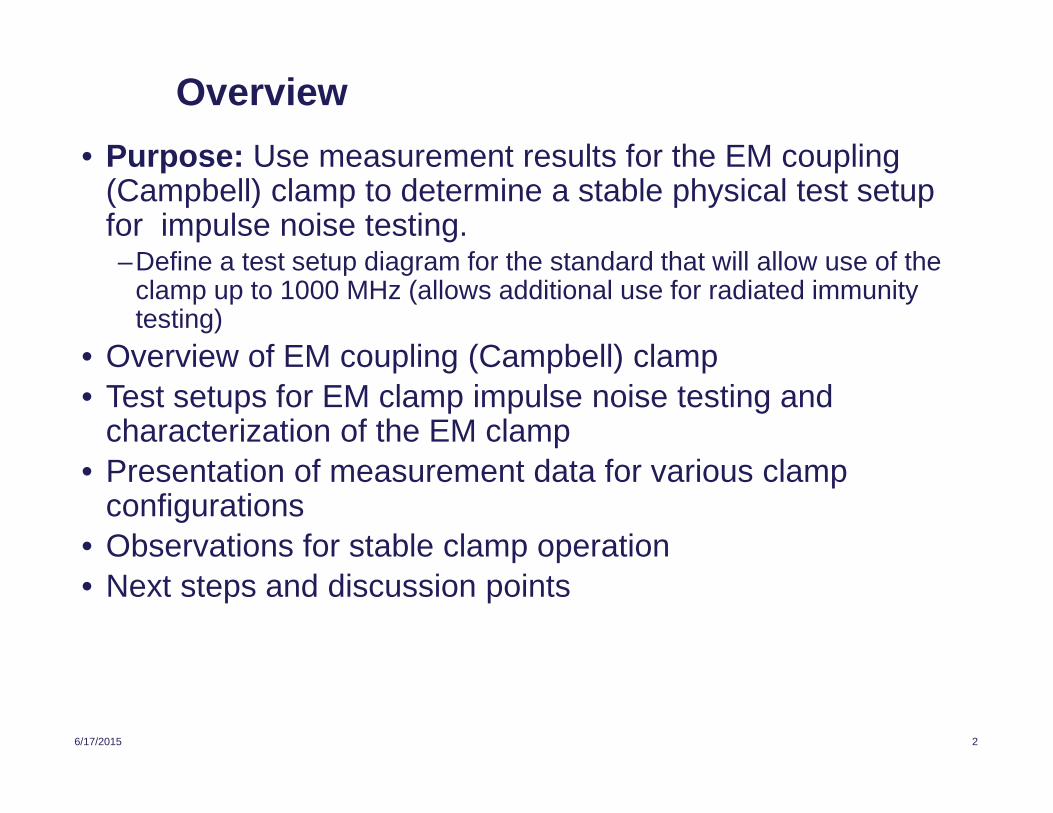
Overview
• Purpose: Use measurement results for the EM coupling(Campbell) clamp to determine a stable physical test setupfor impulse noise testing.–Define a test setup diagram for the standard that will allow use of the
clamp up to 1000 MHz (allows additional use for radiated immunitytesting)
• Overview of EM coupling (Campbell) clamp
• Test setups for EM clamp impulse noise testing andcharacterization of the EM clamp
• Presentation of measurement data for various clampconfigurations
• Observations for stable clamp operation
• Next steps and discussion points
6/17/2015 3
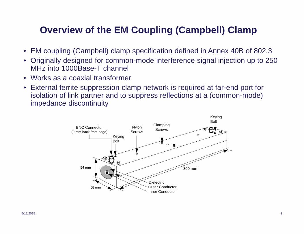
Overview of the EM Coupling (Campbell) Clamp
• EM coupling (Campbell) clamp specification defined in Annex 40B of 802.3
• Originally designed for common-mode interference signal injection up to 250MHz into 1000Base-T channel
• Works as a coaxial transformer
• External ferrite suppression clamp network is required at far-end port forisolation of link partner and to suppress reflections at a (common-mode)impedance discontinuity
DielectricOuter ConductorInner Conductor
300 mm
NylonScrews
ClampingScrews
KeyingBolt
KeyingBolt
BNC Connector(9 mm back from edge)
6/17/2015 4
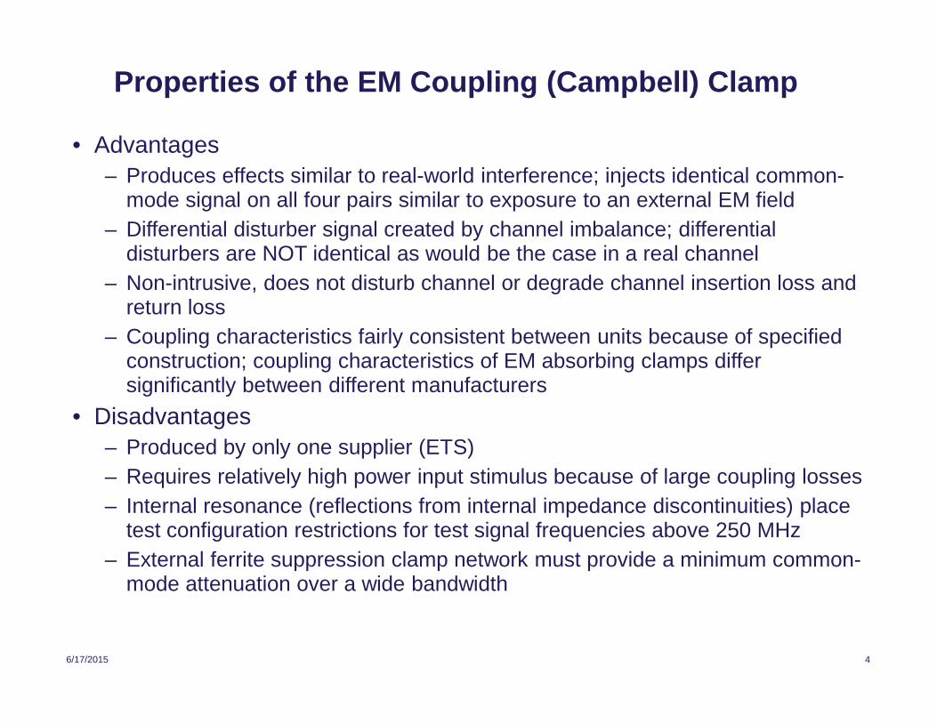
Properties of the EM Coupling (Campbell) Clamp
• Advantages
– Produces effects similar to real-world interference; injects identical common-mode signal on all four pairs similar to exposure to an external EM field
– Differential disturber signal created by channel imbalance; differentialdisturbers are NOT identical as would be the case in a real channel
– Non-intrusive, does not disturb channel or degrade channel insertion loss andreturn loss
– Coupling characteristics fairly consistent between units because of specifiedconstruction; coupling characteristics of EM absorbing clamps differsignificantly between different manufacturers
• Disadvantages
– Produced by only one supplier (ETS)
– Requires relatively high power input stimulus because of large coupling losses
– Internal resonance (reflections from internal impedance discontinuities) placetest configuration restrictions for test signal frequencies above 250 MHz
– External ferrite suppression clamp network must provide a minimum common-mode attenuation over a wide bandwidth
6/17/2015 5
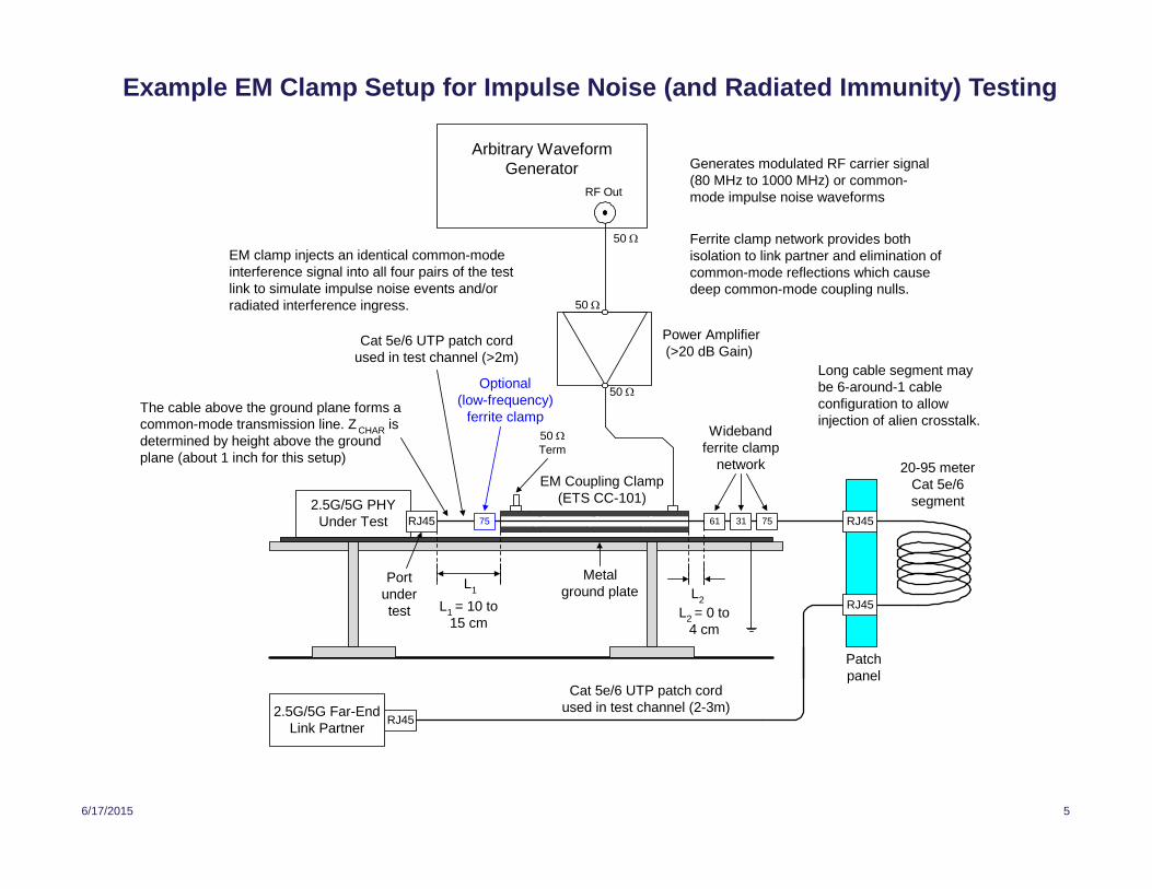
Example EM Clamp Setup for Impulse Noise (and Radiated Immunity) Testing
2.5G/5G PHYUnder Test
Widebandferrite clamp
network
L1
Cat 5e/6 UTP patch cordused in test channel (>2m)
L1
= 10 to15 cm
Arbitrary WaveformGenerator
RF Out
Metalground plate
50
Patchpanel
EM clamp injects an identical common-modeinterference signal into all four pairs of the testlink to simulate impulse noise events and/orradiated interference ingress.
RJ45
RJ45
RJ45
20-95 meterCat 5e/6segment
Cat 5e/6 UTP patch cordused in test channel (2-3m)
Portundertest
50
50
61 31
Power Amplifier(>20 dB Gain)
Generates modulated RF carrier signal(80 MHz to 1000 MHz) or common-mode impulse noise waveforms
EM Coupling Clamp(ETS CC-101)
50 Term
2.5G/5G Far-EndLink Partner
Ferrite clamp network provides bothisolation to link partner and elimination ofcommon-mode reflections which causedeep common-mode coupling nulls.
Long cable segment maybe 6-around-1 cableconfiguration to allowinjection of alien crosstalk.
The cable above the ground plane forms acommon-mode transmission line. Z
CHARis
determined by height above the groundplane (about 1 inch for this setup)
75
L2 = 0 to4 cm
L2
RJ45 75
Optional(low-frequency)
ferrite clamp
6/17/2015 6
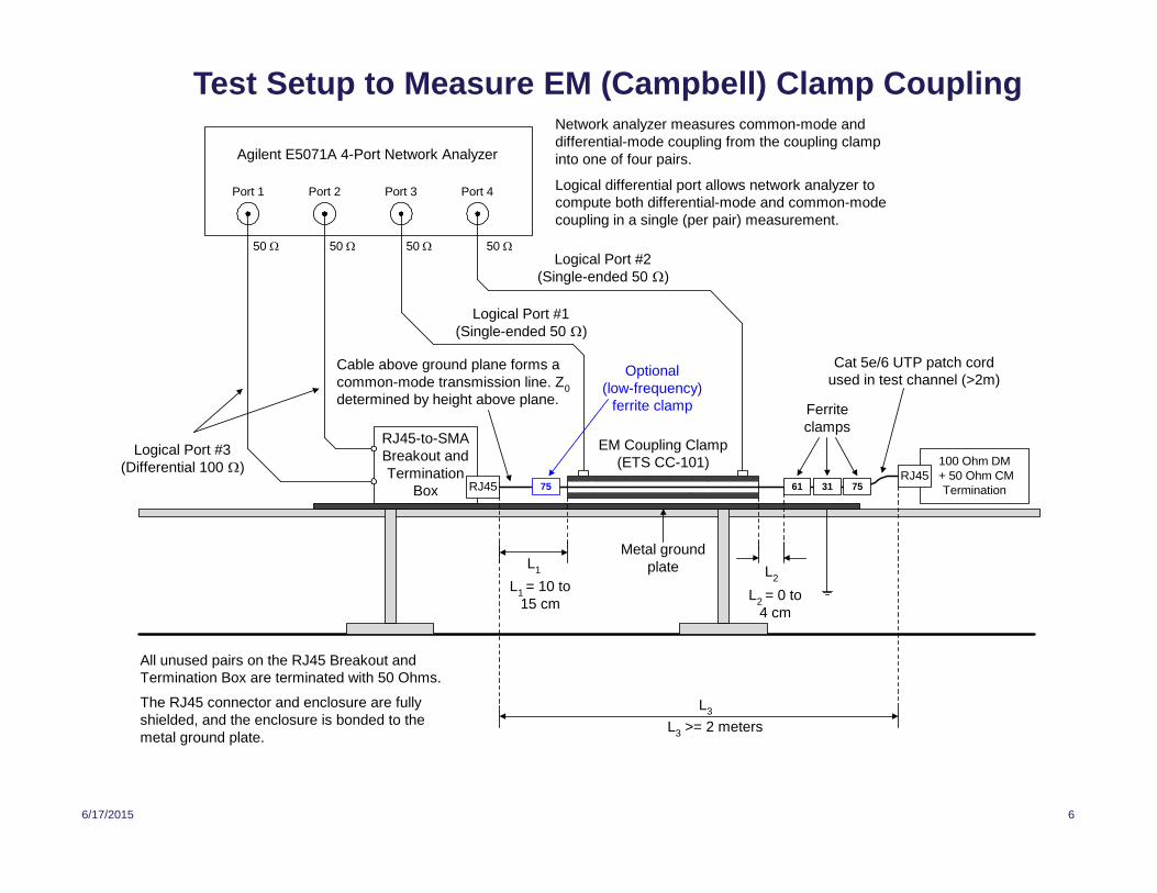
Test Setup to Measure EM (Campbell) Clamp Coupling
100 Ohm DM+ 50 Ohm CMTermination
EM Coupling Clamp(ETS CC-101)
L3
RJ45-to-SMABreakout andTermination
Box 61
Logical differential port allows network analyzer tocompute both differential-mode and common-modecoupling in a single (per pair) measurement.
50 50
L3
>= 2 meters
Agilent E5071A 4-Port Network Analyzer
Logical Port #3(Differential 100 )
Port 1 Port 2 Port 3 Port 4
50
Metal groundplate
Network analyzer measures common-mode anddifferential-mode coupling from the coupling clampinto one of four pairs.
50
All unused pairs on the RJ45 Breakout andTermination Box are terminated with 50 Ohms.
The RJ45 connector and enclosure are fullyshielded, and the enclosure is bonded to themetal ground plate.
Cat 5e/6 UTP patch cordused in test channel (>2m)
Cable above ground plane forms acommon-mode transmission line. Z
0
determined by height above plane.
RJ45
Logical Port #2(Single-ended 50 )
Logical Port #1(Single-ended 50 )
RJ4531 75
Ferriteclamps
L2
= 0 to4 cm
L2
L1
L1= 10 to
15 cm
75
Optional(low-frequency)
ferrite clamp
6/17/2015 7
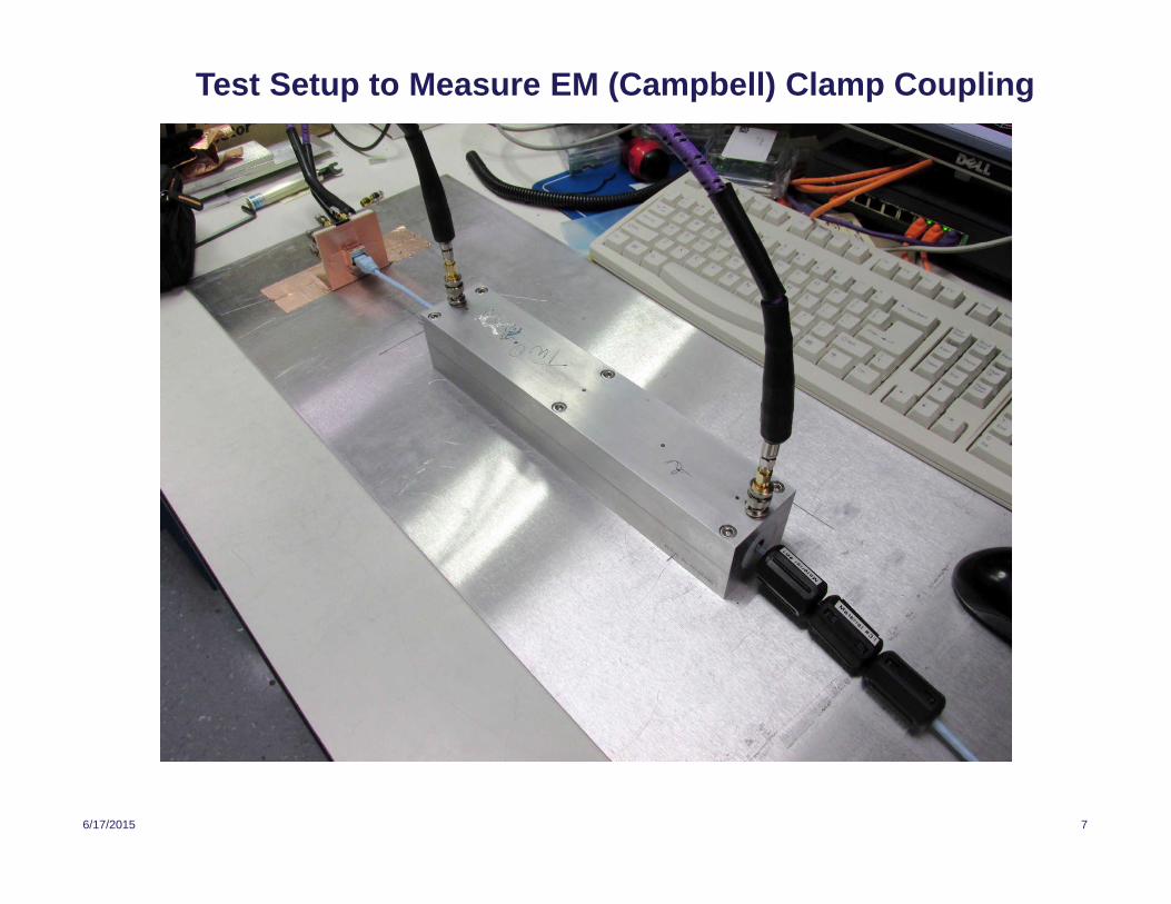
Test Setup to Measure EM (Campbell) Clamp Coupling
6/17/2015 8
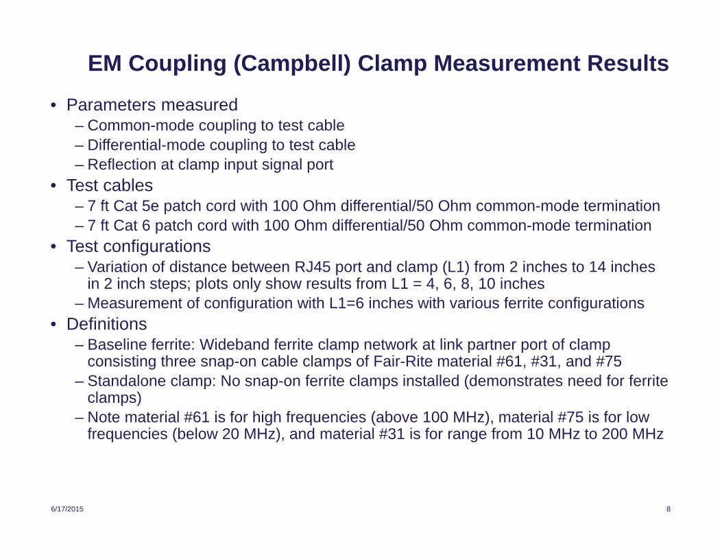
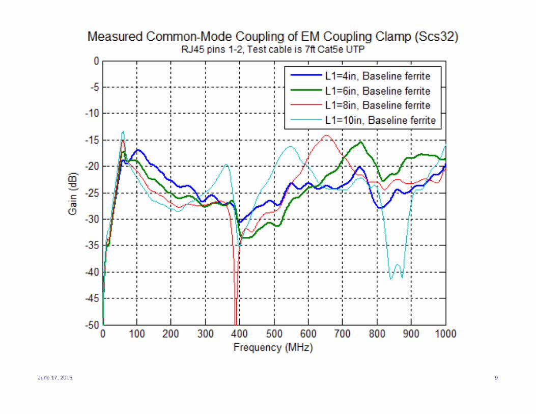
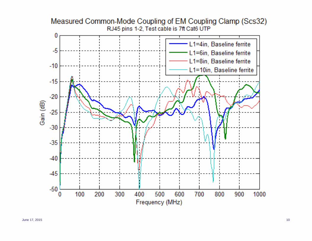
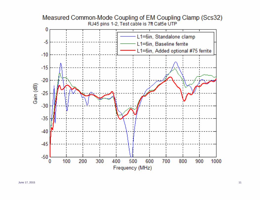
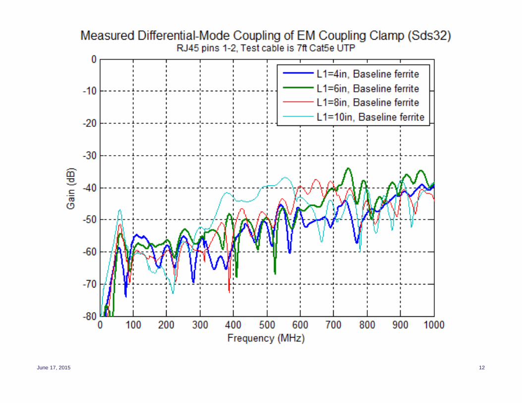
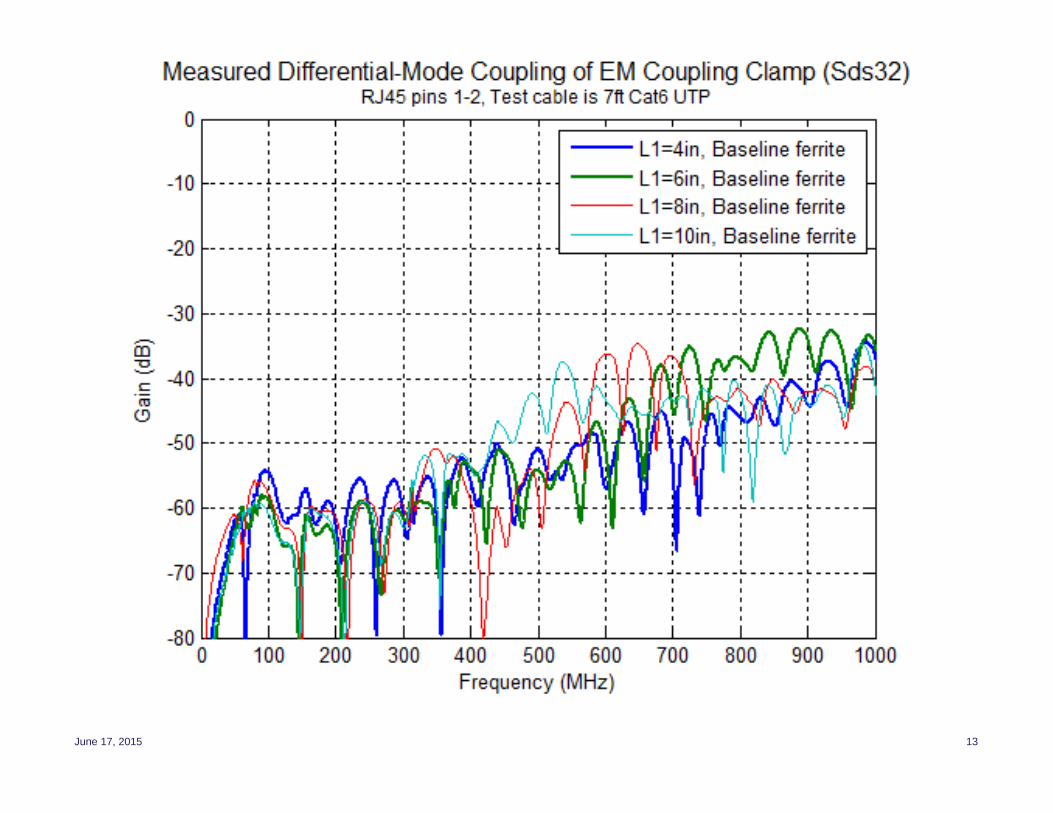
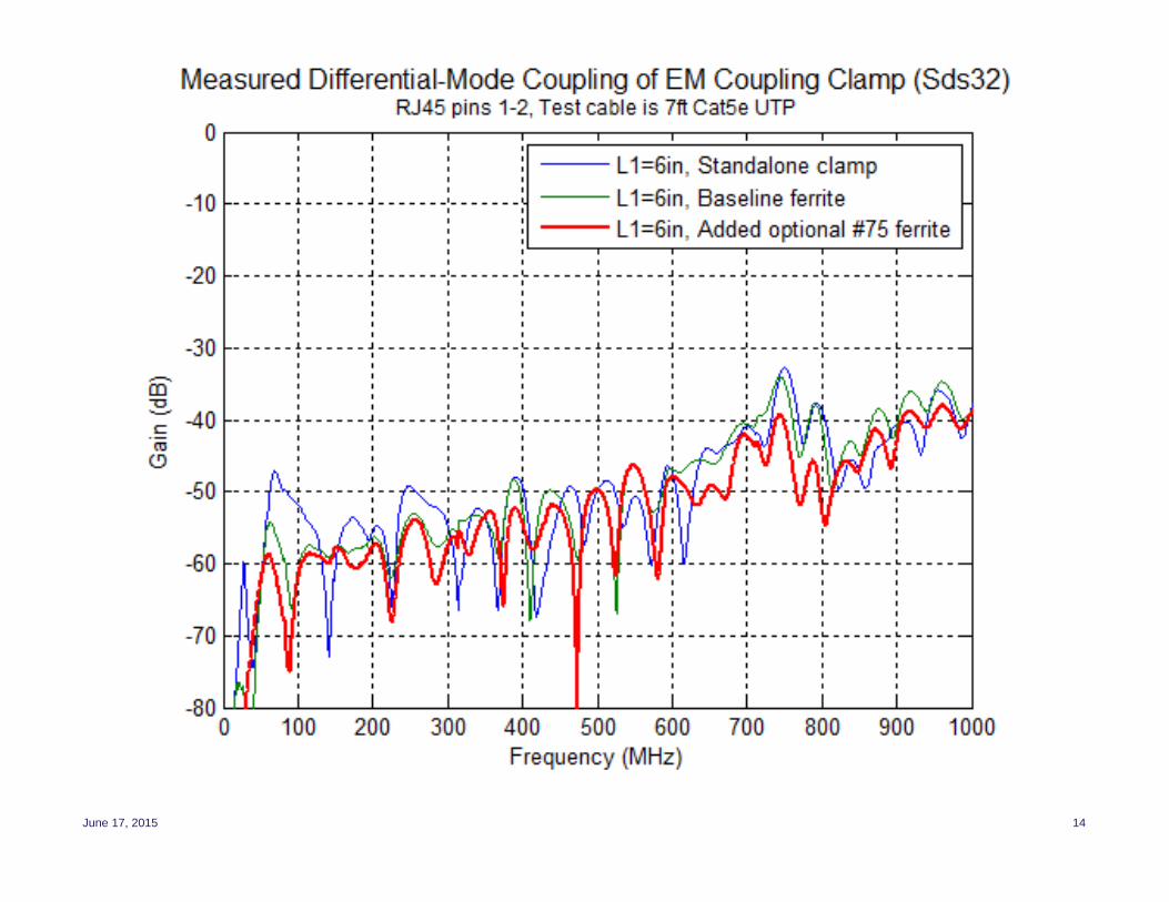
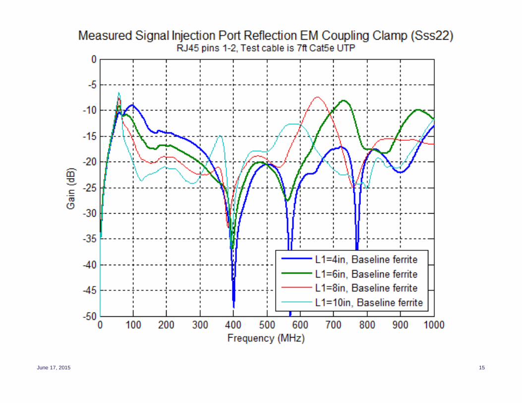
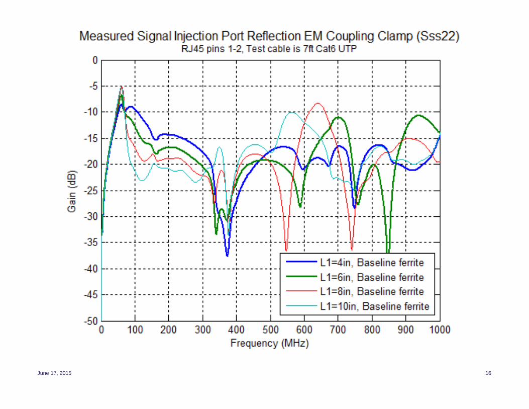
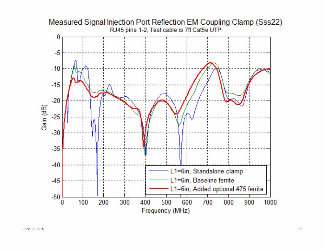
EM Coupling (Campbell) Clamp Measurement Results
• Parameters measured– Common-mode coupling to test cable
– Differential-mode coupling to test cable
– Reflection at clamp input signal port
• Test cables– 7 ft Cat 5e patch cord with 100 Ohm differential/50 Ohm common-mode termination
– 7 ft Cat 6 patch cord with 100 Ohm differential/50 Ohm common-mode termination
• Test configurations– Variation of distance between RJ45 port and clamp (L1) from 2 inches to 14 inches
in 2 inch steps; plots only show results from L1 = 4, 6, 8, 10 inches
– Measurement of configuration with L1=6 inches with various ferrite configurations
• Definitions– Baseline ferrite: Wideband ferrite clamp network at link partner port of clamp
consisting three snap-on cable clamps of Fair-Rite material #61, #31, and #75
– Standalone clamp: No snap-on ferrite clamps installed (demonstrates need for ferriteclamps)
– Note material #61 is for high frequencies (above 100 MHz), material #75 is for lowfrequencies (below 20 MHz), and material #31 is for range from 10 MHz to 200 MHz
June 17, 2015 9
June 17, 2015 10
June 17, 2015 11
June 17, 2015 12
June 17, 2015 13
June 17, 2015 14
June 17, 2015 15
June 17, 2015 16
June 17, 2015 17
6/17/2015 18
Observations from EM Coupling Clamp Measurements
• Define “usable bandwidth” as a region where the common-mode coupling transferfunction is reasonably flat and does not have any deep nulls
• The wideband ferrite clamp network at the link partner (far-end) port of the clamp isMANDATORY for all usable test configuration to provide isolation for auxiliaryequipment and eliminate coupling nulls from common-mode reflections
• For usable bandwidth to 350 MHz with Cat 5e UTP and Cat 6 UTP, L1 (distancebetween clamp and DUT) can widely vary from 10 cm to 30 cm (4 inches to 12 inches)
• For usable bandwidth beyond 350 MHz up to 1GHz with Cat 5e UTP and Cat 6 UTP,L1 (distance between clamp and DUT) should be between 10 cm and 15 cm (4 and 6inches), possibly less than 15 cm (6 inches) maximum for Cat 6 UTP
• The addition of 0.25 inch thick small metal slabs between the clamp and DUT (RJ45test port) to reduce the height of the test cable above the ground plane (reducecommon-mode impedance) slightly improved
• Added low-frequency ferrite clamp (material #75) improves clamp input port returnloss and flattens common-mode coupling curve, but reduces low frequency common-mode coupling
• The low frequency common-mode coupling loss is very high; this may be problem forEFT waveform impulse noise testing
• The test setup diagram shown in slide #5 may be useful as a starting point indefining a test setup for impulse noise testing in the standard
6/17/2015 19
Next Steps and Discussion Points
• Measure impedance of ferrite clamp network to provide a proper standardspecification
• Test clamp coupling with screened and shielded cable
• Should an RJ45 junction be added 2 to 3 meters from the DUT port on thetest cable configuration?– Realistic installation practice; simulates patch cord run from desk/wall RJ45
jack to network equipment
– Increases common-mode to differential conversion
• Should we consider alternative test setups with either an EM absorbingclamp or a differential injection test fixture?