Embed Size (px)
Citation preview
Physical Transmission Media
Chapter 8
Objectives
In this chapter, you will learn to: Identify the characteristics of wireline transmission Describe the properties and uses of coaxial cable Describe the properties and uses of different types of twisted-
pair wire Identify the characteristics of lightwave transmission Describe the properties and uses of fiber optic cable Identify factors to consider when selecting a
telecommunications medium Explain and apply cabling standards Describe best practices for installing wire and fiber optic cabling Identify techniques for testing the continuity and performance of
physical transmission media
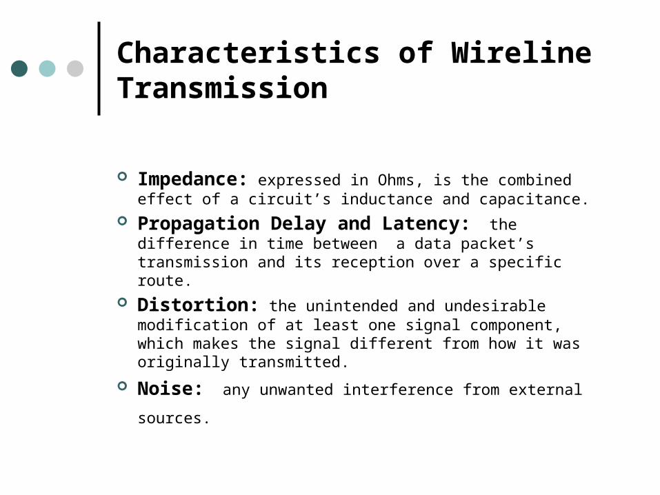
Characteristics of Wireline Transmission
Impedance: expressed in Ohms, is the combined effect of a circuit’s inductance and capacitance.
Propagation Delay and Latency: the difference in time between a data packet’s transmission and its reception over a specific route.
Distortion: the unintended and undesirable modification of at least one signal component, which makes the signal different from how it was originally transmitted.
Noise: any unwanted interference from external sources.
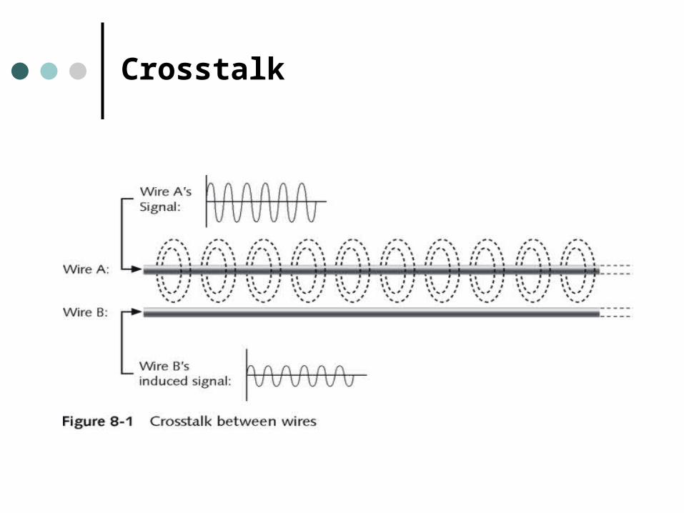
Crosstalk
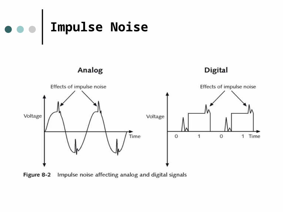
Impulse Noise
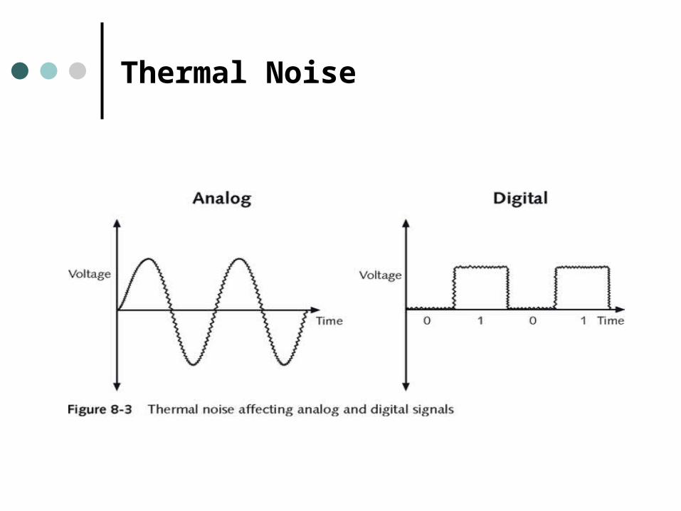
Thermal Noise
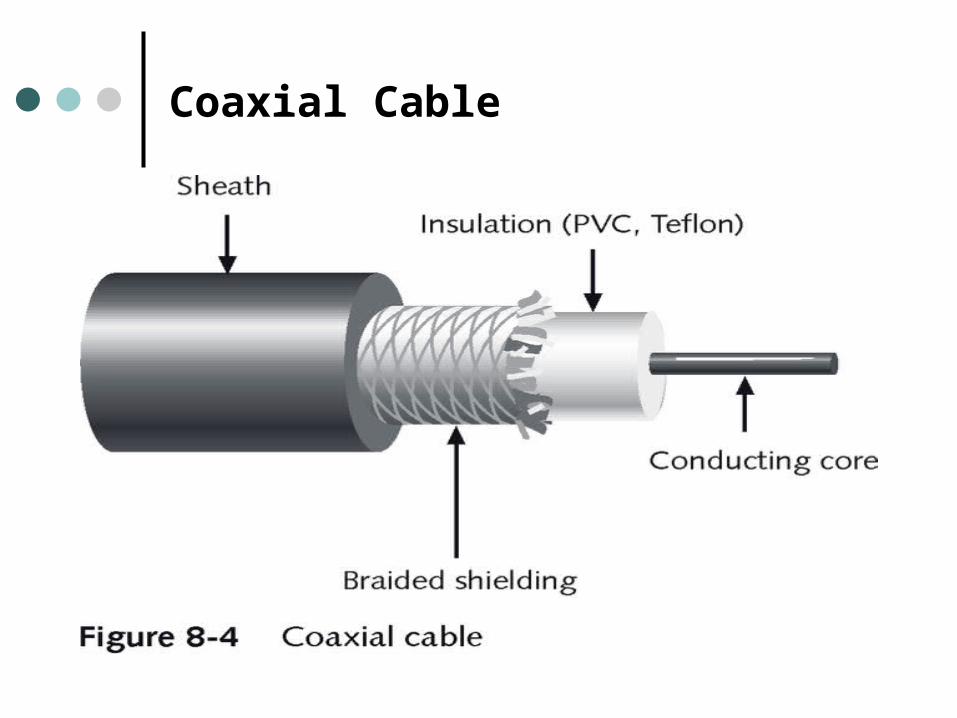
Coaxial Cable
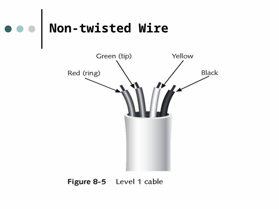
Non-twisted Wire
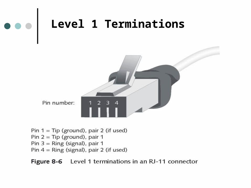
Level 1 Terminations
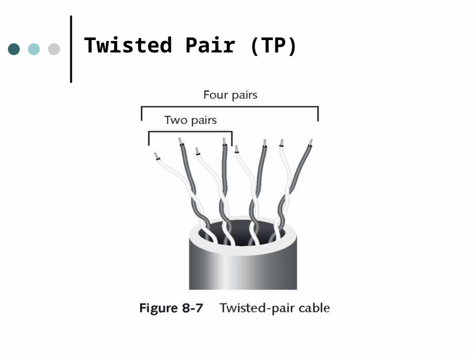
Twisted Pair (TP)
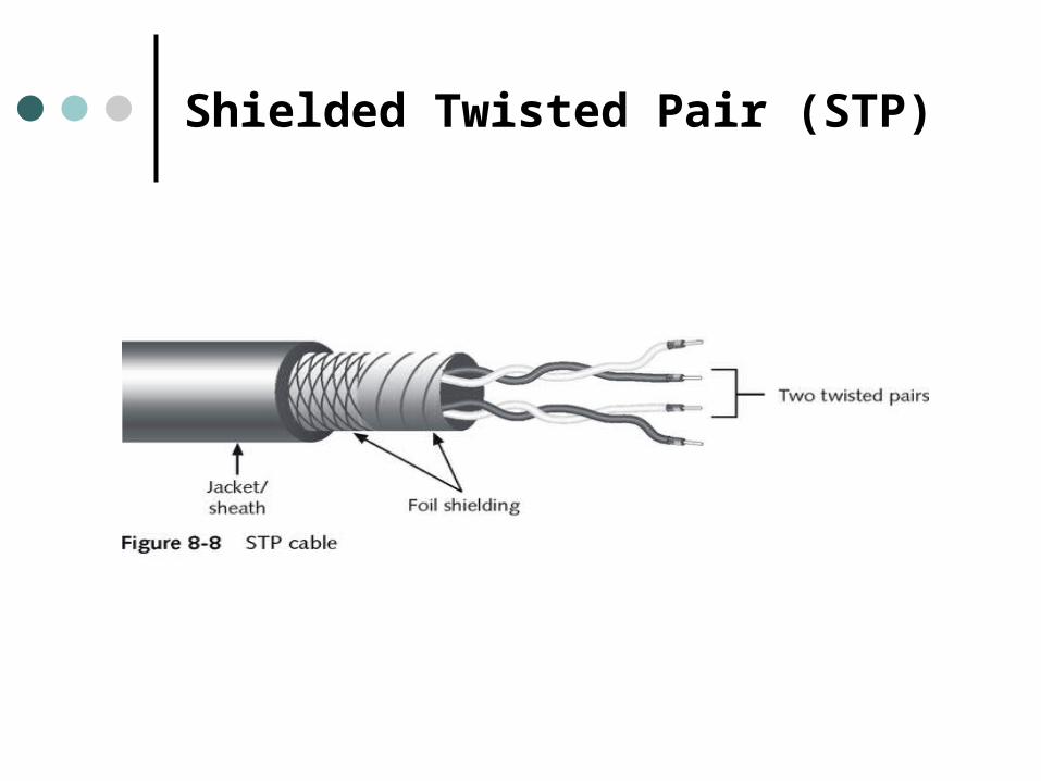
Shielded Twisted Pair (STP)
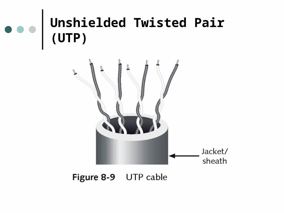
Unshielded Twisted Pair (UTP)
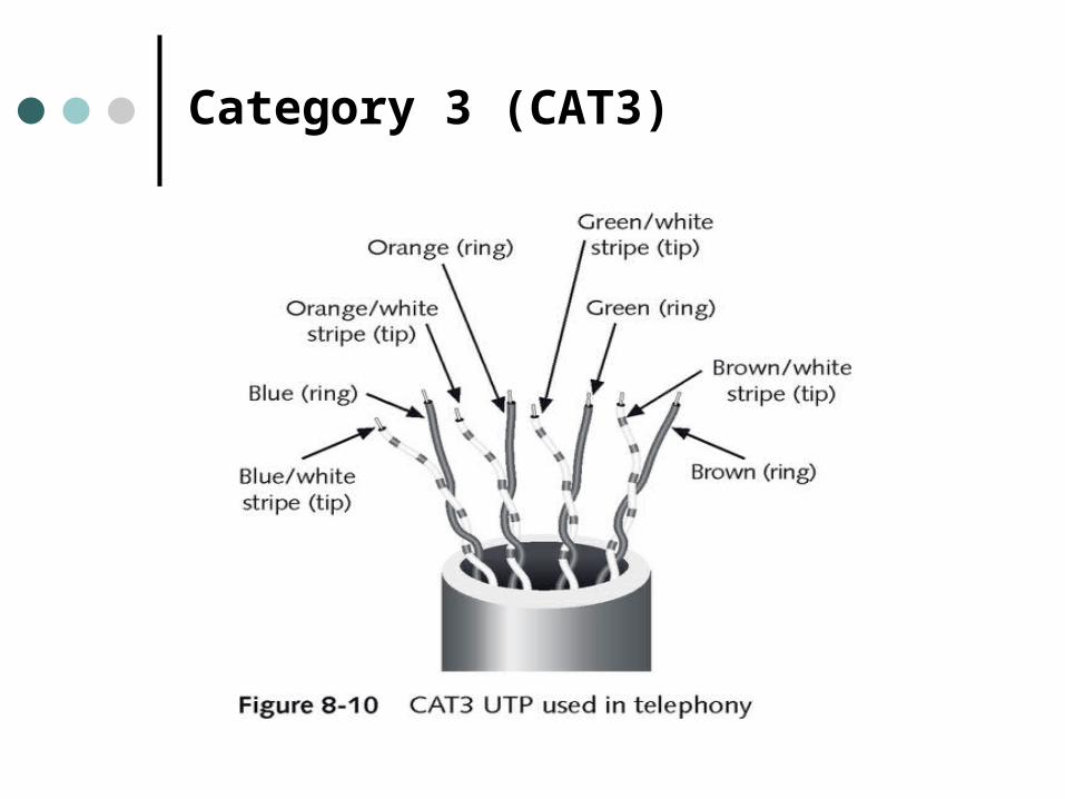
Category 3 (CAT3)
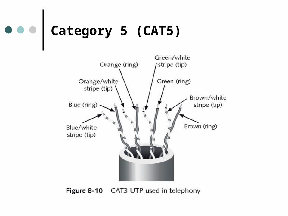
Category 5 (CAT5)
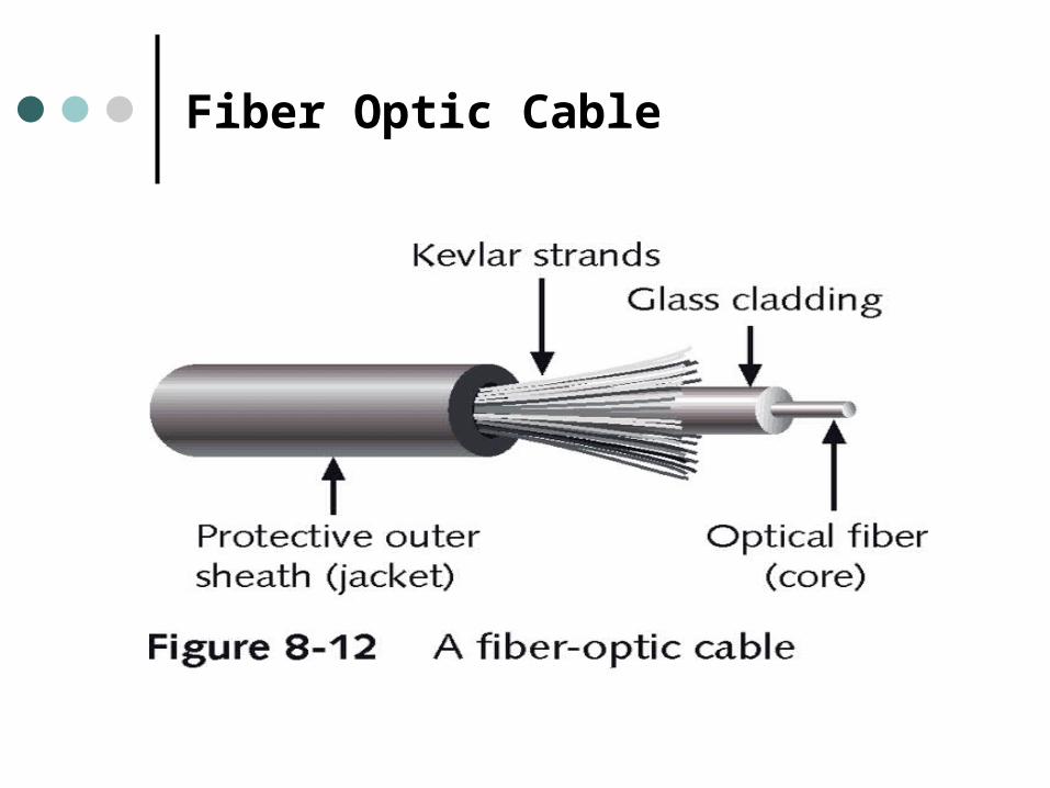
Fiber Optic Cable
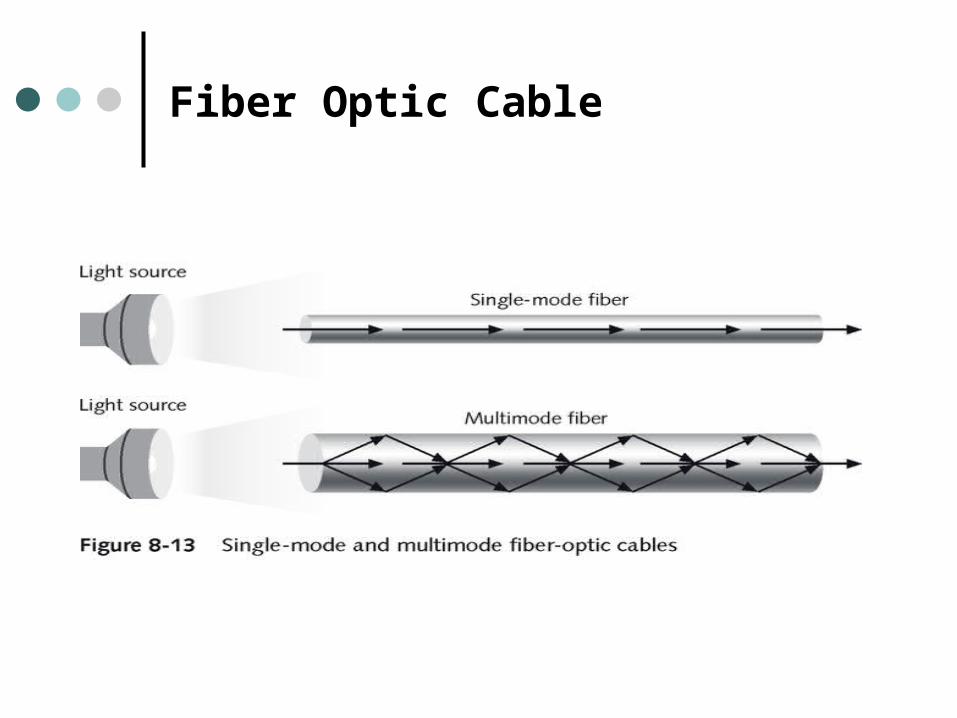
Fiber Optic Cable
Popular Uses for Fiber Optic Cable
Includes connecting: Regional and local cable TV facilities Internet NAPs with other large
telecommunications exchange point Central offices with other central offices Main feeders with central offices A telecommunication’s network with private
LANs A telecommunication’s network with private
switching systems, such as PBX
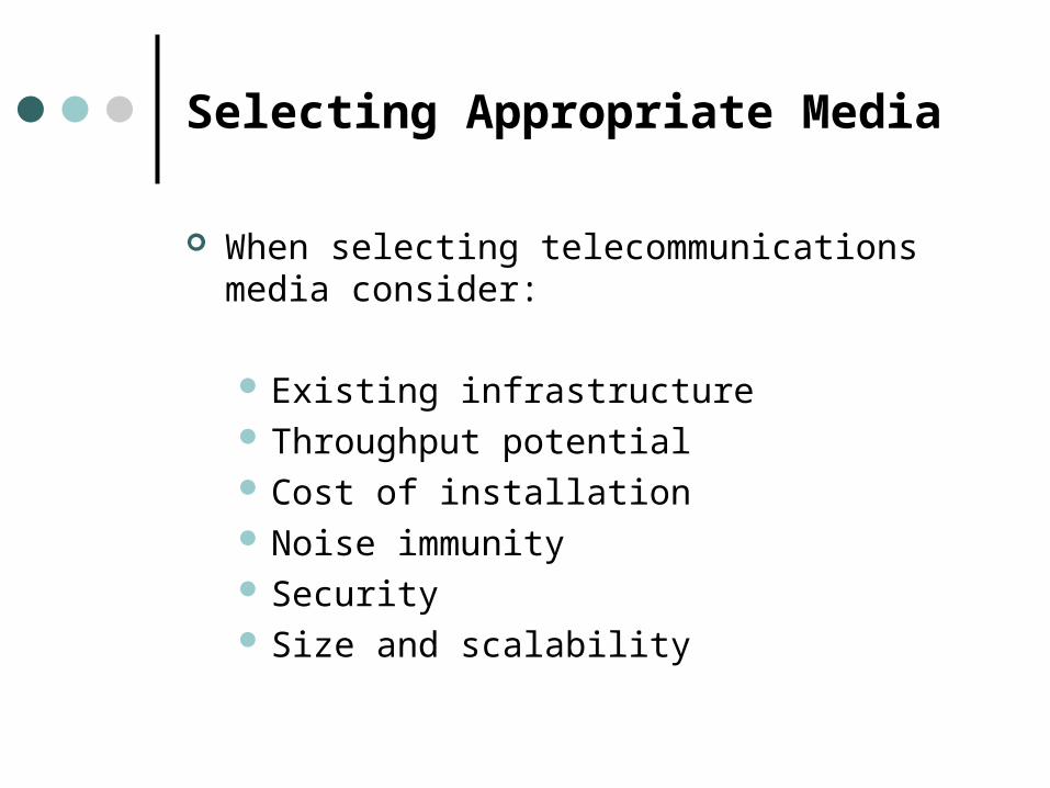
Selecting Appropriate Media
When selecting telecommunications media consider:
Existing infrastructure Throughput potential Cost of installation Noise immunity Security Size and scalability
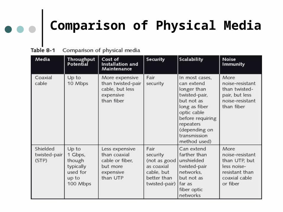
Comparison of Physical Media
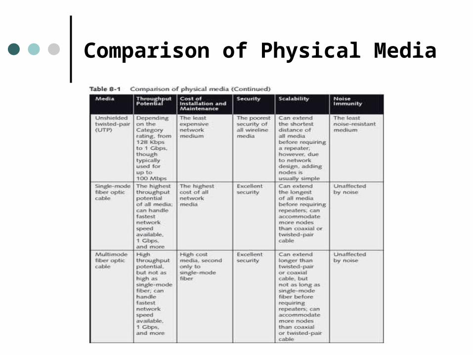
Comparison of Physical Media
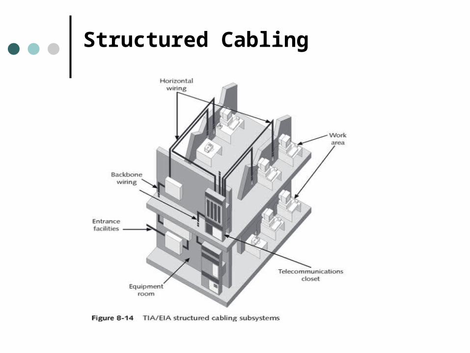
Structured Cabling
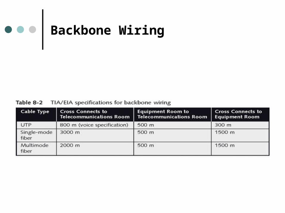
Backbone Wiring
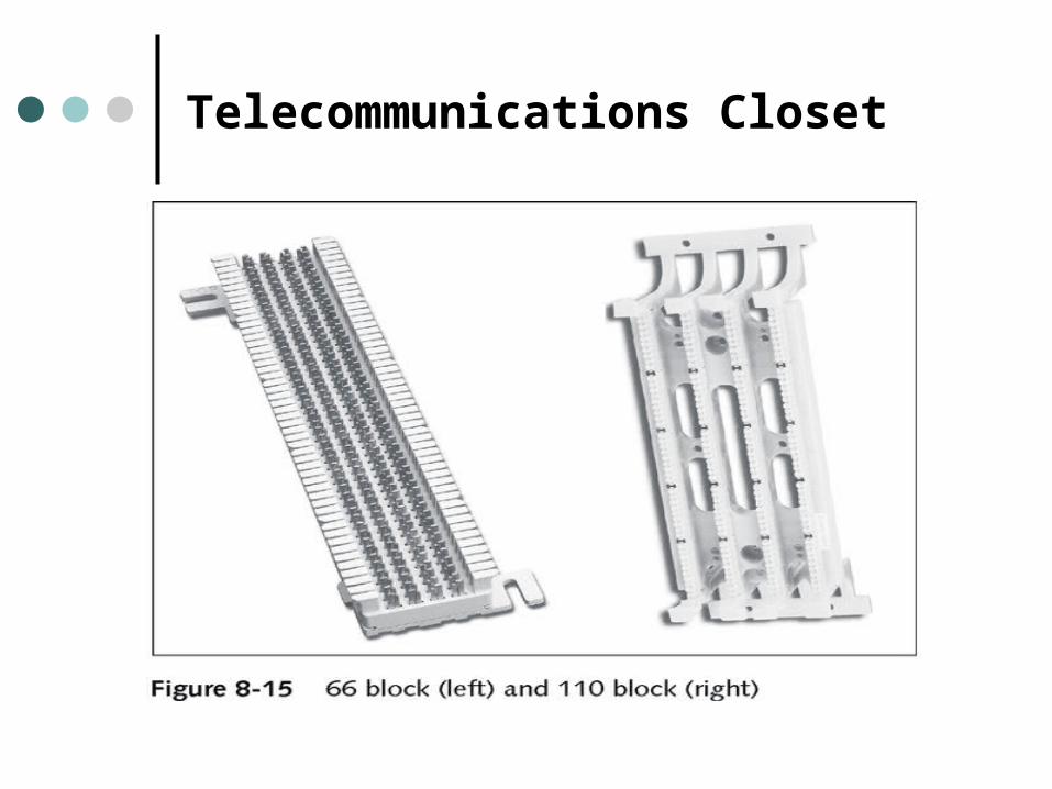
Telecommunications Closet
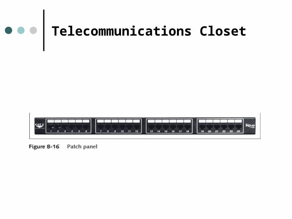
Telecommunications Closet
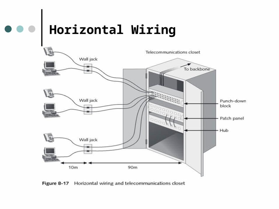
Horizontal Wiring
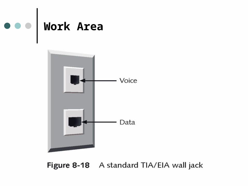
Work Area
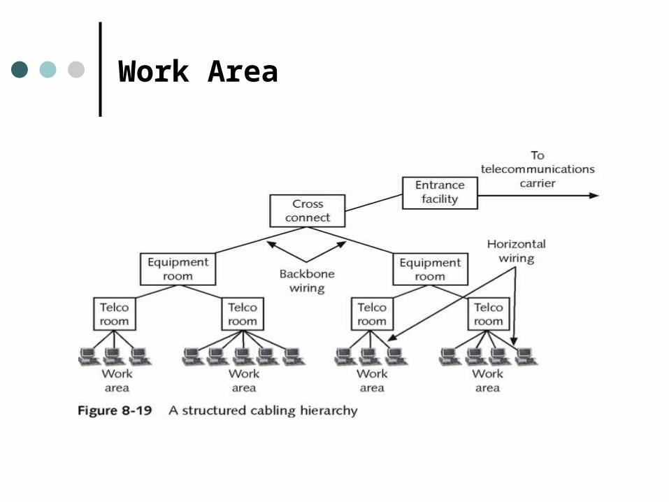
Work Area
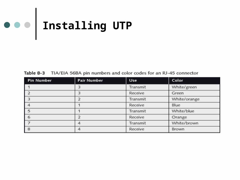
Installing UTP
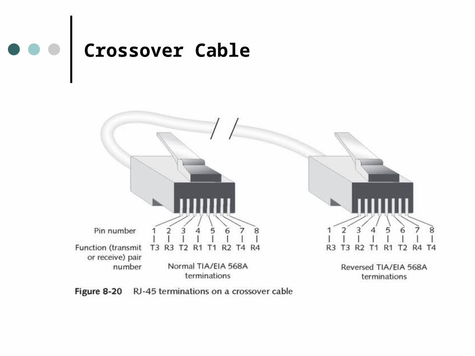
Crossover Cable
Installation Tips for CAT5 UTP
Do not untwist twisted-pair cables more than one-half inch before inserting them into the punch-down block or connector.
Pay attention to the bend radius limitations for the type of cable you are installing.
Test each segment of cabling as you install it with a cable tester.
Use only cable ties to cinch groups of cables together
Installation Tips for CAT5 UTP
When pulling cable, do not exert more than 25 pounds of pressure on the cable.
Avoid laying cable across the floor where it might sustain damage from rolling chairs or foot traffic.
Install cable at least three feet away from fluorescent lights or other sources of EMI.
Always leave slack in cable runs.
Installing Fiber
Splice - the physical joining of two facing and aligned pieces of wire or fiber.
Mechanical splicing - the two ends of a fiber optic cable are fixed in position within a tube so that they form one continuous communications channel.
Fusion splicing - a connection between fibers is accomplished through the application of heat and the resulting melting and fusion of two fiber strands.
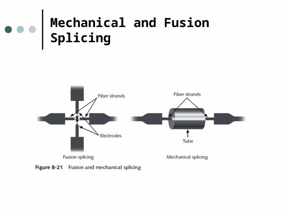
Mechanical and Fusion Splicing
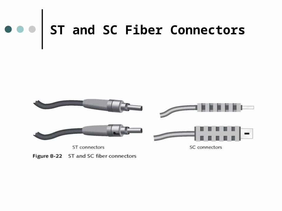
ST and SC Fiber Connectors
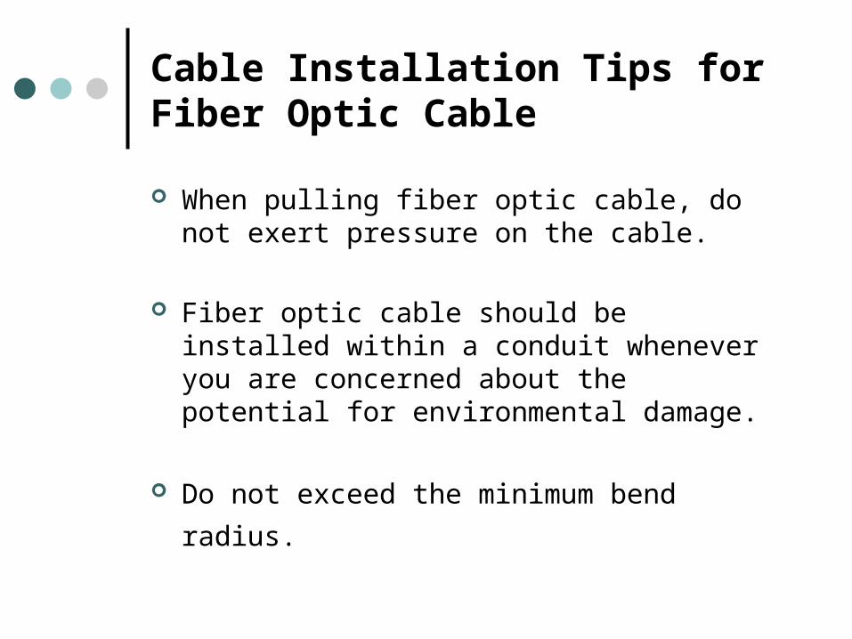
Cable Installation Tips for Fiber Optic Cable
When pulling fiber optic cable, do not exert pressure on the cable.
Fiber optic cable should be installed within a conduit whenever you are concerned about the potential for environmental damage.
Do not exceed the minimum bend radius.
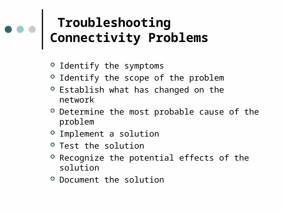
Troubleshooting Connectivity Problems
Identify the symptoms Identify the scope of the problem Establish what has changed on the network Determine the most probable cause of the
problem Implement a solution Test the solution Recognize the potential effects of the solution Document the solution
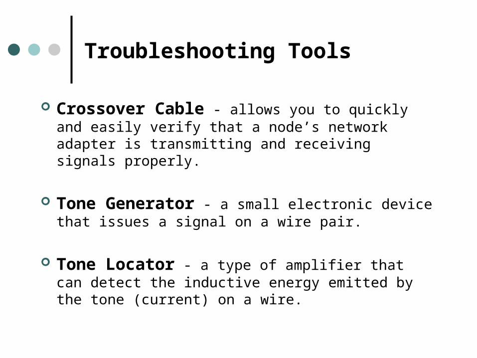
Troubleshooting Tools
Crossover Cable - allows you to quickly and easily verify that a node’s network adapter is transmitting and receiving signals properly.
Tone Generator - a small electronic device that issues a signal on a wire pair.
Tone Locator - a type of amplifier that can detect the inductive energy emitted by the tone (current) on a wire.
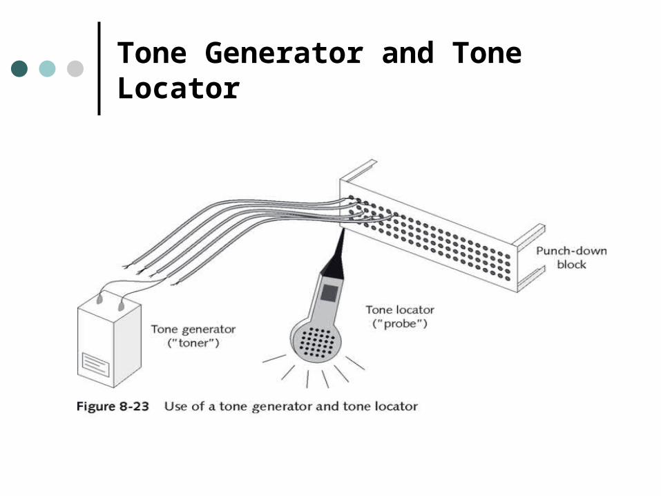
Tone Generator and Tone Locator
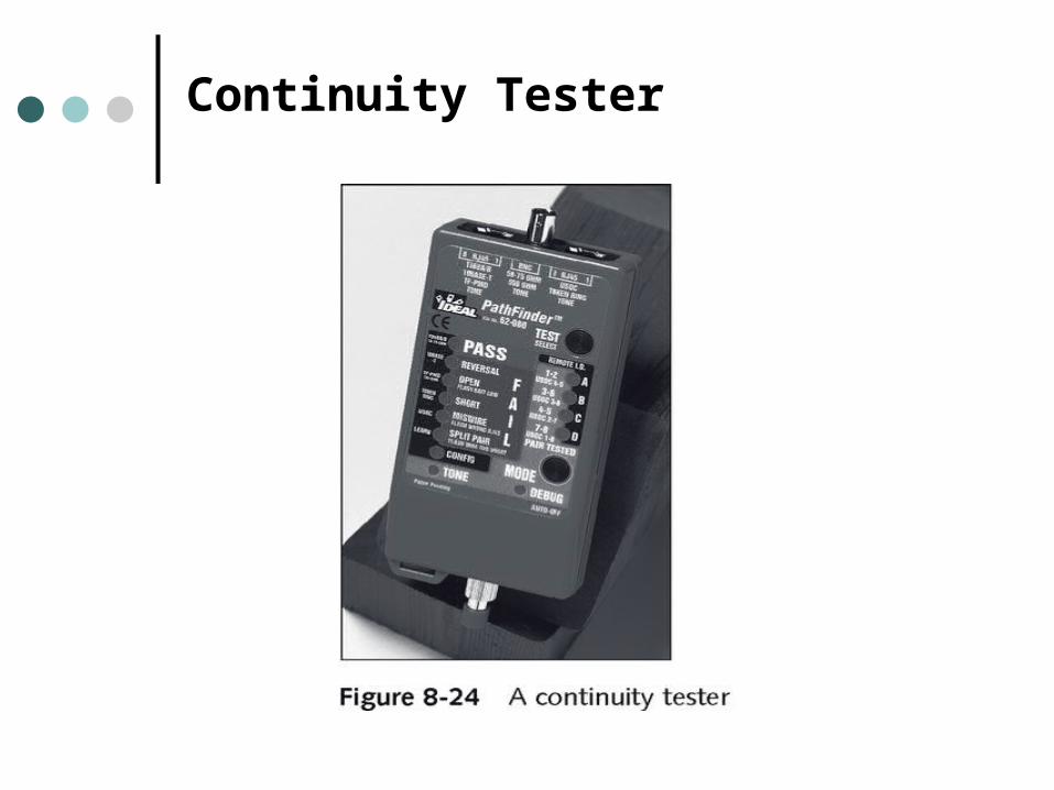
Continuity Tester
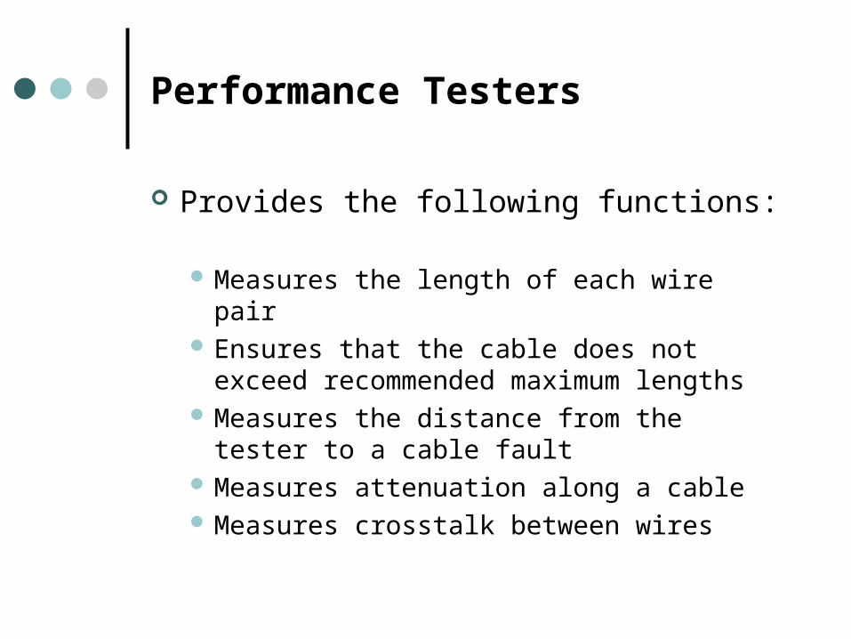
Performance Testers
Provides the following functions:
Measures the length of each wire pair Ensures that the cable does not exceed
recommended maximum lengths Measures the distance from the tester to a
cable fault Measures attenuation along a cable Measures crosstalk between wires
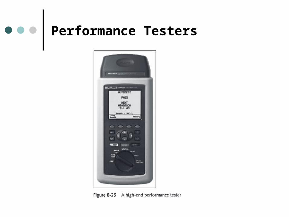
Performance Testers
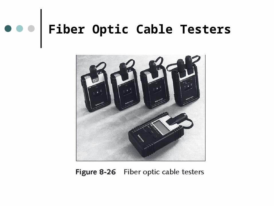
Fiber Optic Cable Testers
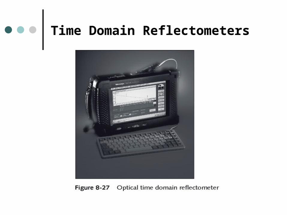
Time Domain Reflectometers
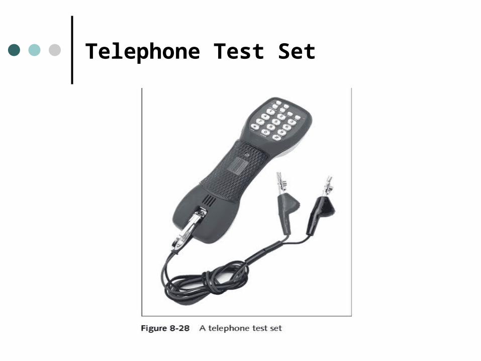
Telephone Test Set
Summary
Characteristics that affect wireline transmission include impedance changes, latency, delay distortion, and noise.
Traditional four-pair, non-twisted copper telephone wiring is known as Level 1 cable or quad wire.
Category (CAT3) UTP cable is the minimum grade of unshielded twisted-pair cabling for use in telephone systems.
To identify the source of cabling infrastructure problems, follow a logical troubleshooting methodology and have the appropriate testing tools handy.