Embed Size (px)
Citation preview

Colin Perkins | https://csperkins.org/ | Copyright © 2017 | This work is licensed under the Creative Commons Attribution-NoDerivatives 4.0 International License. To view a copy of this license, visit http://creativecommons.org/licenses/by-nd/4.0/ or send a letter to Creative Commons, PO Box 1866, Mountain View, CA 94042, USA.
Physical Layer
Networked Systems (H) Lecture 3

Colin Perkins | https://csperkins.org/ | Copyright © 2017
Lecture Outline
• Physical layer concepts
• Wired links
• Wireless links
• Channel capacity
2
Colin Perkins | https://csperkins.org/ | Copyright © 2017
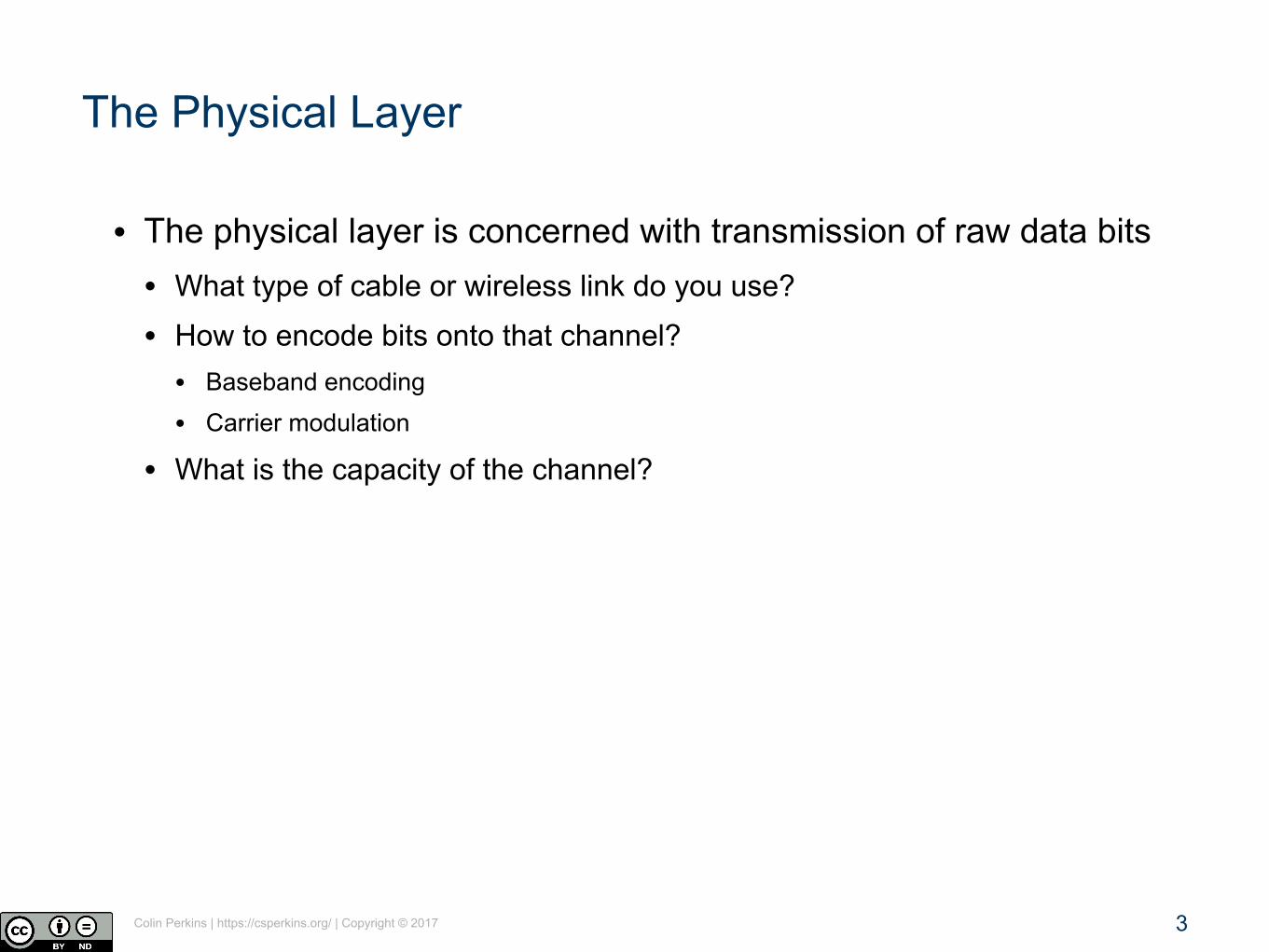
The Physical Layer
• The physical layer is concerned with transmission of raw data bits • What type of cable or wireless link do you use?
• How to encode bits onto that channel? • Baseband encoding
• Carrier modulation
• What is the capacity of the channel?
3
Colin Perkins | https://csperkins.org/ | Copyright © 2017
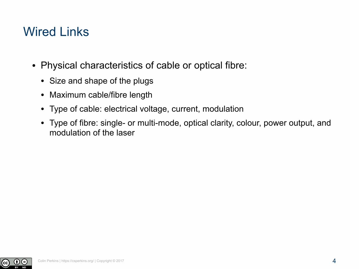
Wired Links
• Physical characteristics of cable or optical fibre: • Size and shape of the plugs
• Maximum cable/fibre length
• Type of cable: electrical voltage, current, modulation
• Type of fibre: single- or multi-mode, optical clarity, colour, power output, and modulation of the laser
4

Colin Perkins | https://csperkins.org/ | Copyright © 2017
Unshielded Twisted Pair
• Electrical cable using two wires twisted together • Each pair is unidirectional: signal and ground
• Twists reduce interference and noise pickup: more twists → less noise
• Cable lengths of several miles possible at low data rates; ~100 metres at high rates
• Susceptibility to noise increases with cable length
• Extremely widely deployed: • Ethernet cables
• Telephone lines
5

Colin Perkins | https://csperkins.org/ | Copyright © 2017
Source: Wikipedia/Bob Mellish/CC BY-SA 3.0
Optical Fibre
• Glass core and cladding, contained in plastic jacket for protection • Somewhat fragile: glass can crack if bent sharply
• Unidirectional data: transmission laser at one end; photodetector at the other • Laser light trapped in fibre by total internal reflection
• Very low noise, since electromagnetic interference does not affect light
• Very high capacity: 10s of Gbps over 100s of miles
• Very cheap to manufacture
• Requires relatively expensive lasers to operate
6

Colin Perkins | https://csperkins.org/ | Copyright © 2017
Wired Data Transmission
• Signal usually directly encoded onto the channel
• Encoding performed by varying the voltage in an electrical cable, or the intensity of light in an optical fibre
• Many encoding schemes exist: NRZ, NRZI, Manchester, 4B/5B, etc.
7
Sig
nal s
treng
th
0 H
Bas
eban
d
Signal usually occupies baseband region
The bandwidth of the signal is denoted H, and is the frequency range used
Frequency

Colin Perkins | https://csperkins.org/ | Copyright © 2017
Non-Return to Zero Encoding
Time
Volta
ge
0
5
3
4
2
1 0-2V codes 0
3-5V codes 1
• Encode a 1 as a high signal, a 0 as a low signal
8

Colin Perkins | https://csperkins.org/ | Copyright © 2017
• Encode a 1 as a high signal, a 0 as a low signal
• Limitations with runs of consecutive same bit: • Baseline wander
• Clock recovery
Non-Return to Zero Encoding
Bits:
NRZ:
0 10 0 1 1 1 1 0 1 0 0 0 0 1 0
9

Colin Perkins | https://csperkins.org/ | Copyright © 2017
NRZ Inverted Encoding
• Encode a 1 as a change in signal value, a 0 as a constant signal
• Solves problems with runs of consecutive 1s, does nothing for runs of consecutive 0s
10
Bits:
NRZ Inverted:
0 10 0 1 1 1 1 0 1 0 0 0 0 1 0

Colin Perkins | https://csperkins.org/ | Copyright © 2017
Manchester Encoding
• Encode a 1 as a high-low transition, a 0 as a low-high transition
• Doubles the bandwidth needed, but avoids the problems with NRZ encoding
11
Bits:
Manchester:
0 10 0 1 1 1 1 0 1 0 0 0 0 1 0

Colin Perkins | https://csperkins.org/ | Copyright © 2017
4B/5B Encoding
• Manchester encoding inefficient – only 50% of link capacity used
• Alternative – insert extra bits to break up sequences of same bit • Each 4 bit data symbol is changed to a 5 bit
code for transmission; reversed at receiver
• Transmit 5 bit codes using NRZI encoding
• 80% of link capacity used for data
4-Bit Data Symbol 5-Bit Encoding
0000 11110
0001 01001
0010 10100
0011 10101
0100 01010
0101 01011
0110 01110
0111 01111
1000 10010
1001 10011
1010 10110
1011 10111
1100 11010
1101 11011
1110 11100
1111 11101
12

Colin Perkins | https://csperkins.org/ | Copyright © 2017
• Baseband data with Manchester coding at 10 Mbps, or 4B/5B coding at 100 Mbps
Example: Ethernet
13
TransmitReceive
4 twisted pairs per cable 3 twists per inch 24 gauge (~0.5mm) copper 100m maximum cable length

Colin Perkins | https://csperkins.org/ | Copyright © 2017
Wireless Links
• Wireless links use carrier modulation, rather than baseband transmission
• Performance affected by: • Carrier frequency
• Transmission power
• Modulation scheme
• Type of antenna, etc.
14
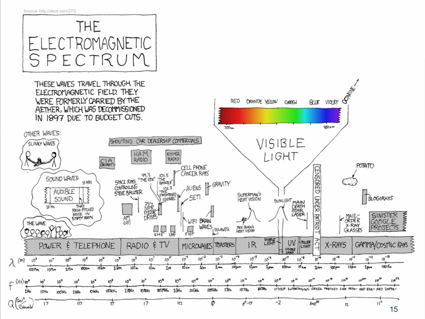
Colin Perkins | https://csperkins.org/ | Copyright © 2017 15
Source: http://xkcd.com/273/

Colin Perkins | https://csperkins.org/ | Copyright © 2017
Carrier Modulation
• Carrier wave applied to channel at frequency, C
• Signal modulated onto the carrier
• Allows multiple signals on a single channel • Provided carriers spaced greater than bandwidth, H, of the signal
• Usually applied to wireless links, but can be used on wired links – this is how ADSL and voice telephones share a phone line
16
Mod
ulat
ed
C
Shifts signal from baseband to a higher carrier frequency
0 H
Bas
eban
dSig
nal s
treng
th
Frequency
H

Colin Perkins | https://csperkins.org/ | Copyright © 2017
Amplitude, Frequency, Phase Modulation
17
Raw signal:
Amplitude modulation:
Frequency modulation:
Phase modulation:

Colin Perkins | https://csperkins.org/ | Copyright © 2017
Complex Modulations
• More complex modulation schemes allow more than one bit to be sent per baud • Use multiple levels of the modulated component
• Example: gigabit Ethernet uses amplitude modulation with five levels, rather than binary signalling
• Combine modulation schemes • Vary both phase and amplitude → quadrature amplitude modulation
• Example: 9600bps modems use 12 phase shift values at two different amplitudes
• Extremely complex combinations regularly used
18

Colin Perkins | https://csperkins.org/ | Copyright © 2017
Spread Spectrum Communication
• Single frequency channels prone to interference • Mitigate by repeatedly changing carrier frequency,
many times per second: noise unlikely to affect all frequencies
• Use a pseudo-random sequence to choose whichcarrier frequency is used for each time slot
• Seed of pseudo-random number generator is sharedsecret between sender and receiver, ensuring security
• Example: 802.11b Wi-Fi uses spread spectrum using several frequencies centred ~2.4 GHz with phase modulation
19
Hedy Lamarr (1914-2000)
Sou
rce:
(Wik
iped
ia/P
ublic
Dom
ain)

Colin Perkins | https://csperkins.org/ | Copyright © 2017
Bandwidth and Channel Capacity
• The bandwidth of a channel determines the frequency range it can transport • Fundamental limitations based on physical properties of the
channel, design of the end points, etc.
• What about digital signals? • Sampling theorem: to accurately digitise an analogue signal,
need 2H samples per second
• Maximum transmission rate of a digital signal depends on channel bandwidth: Rmax = 2H log2 V • Rmax = maximum transmission rate of channel (bits per second)
• H = bandwidth
• V = number of discrete values per symbol
• Assumption: perfect, noise-free, channel
Harry Nyquist (1889-1976)
Sou
rce:
IEE
E20

Colin Perkins | https://csperkins.org/ | Copyright © 2017
Noise
• Real world channels are subject to noise
• Many causes of noise: • Electrical interference
• Cosmic radiation
• Thermal noise
• Corrupts the signal: additive interference
Different noise spectra
21

Colin Perkins | https://csperkins.org/ | Copyright © 2017
Signal to Noise Ratio
• Can measure signal power, S, and noise floor, N, in a channel
• Gives signal-to-noise ratio: S/N • Typically quoted in decibels (dB), not directly
• Signal-to-noise ratio in dB = 10 log10 S/N
• Example: ADSL modems report S/N ~30 for good quality phone lines: signal power 1000x greater than noise
t
Signal
Noise
S/N dB
2 3
10 10
100 20
1000 30
22

Colin Perkins | https://csperkins.org/ | Copyright © 2017
Capacity of a Noisy Channel
• Capacity of noisy channel depends on type of noise • Uniform or bursty; affecting all or some frequencies
• Simplest to model is Gaussian noise: uniform noise that impacts all frequencies equally
• Maximum transmission rate of a channel subject to Gaussian noise: Rmax = H log2(1 + S/N)
Claude Shannon (1916-2001)
Sou
rce:
AT&
TT B
ell L
abs
23

Colin Perkins | https://csperkins.org/ | Copyright © 2017
Capacity of a Noisy Channel
0
10000
20000
30000
40000
50000
60000
0 10000 20000 30000 40000 50000 60000 70000 80000 90000 100000
Max
imum
Dat
a R
ate
S/N
H = 3370 Hz (PSTN)56kbps
Example: maximum date rateof an analogue telephone line
24

Colin Perkins | https://csperkins.org/ | Copyright © 2017
Implications
• Physical characteristics of channel limit amount of information that can be transferred • Bandwidth
• Signal to noise ratio
• These are fundamental limits: might be reached with careful engineering, but cannot be exceeded
25