Embed Size (px)
Citation preview
Physician’s Manual
ENDOTAK RELIANCE
Models 0157/0158/0159
ENDOTAK RELIANCE SModels 0137/0138/0139
Steroid-ElutingExtendable/Retractable Helix
Defibrillation Leads
RESTRICTED DEVICE: Federal law (USA) restricts the sale, distribution, or use of this device to, by, or on the lawful order of a physician.
355458_2.book Page 33 Monday, March 4, 2002 5:07 PM
1
23
4 4
5 5
67
67
8
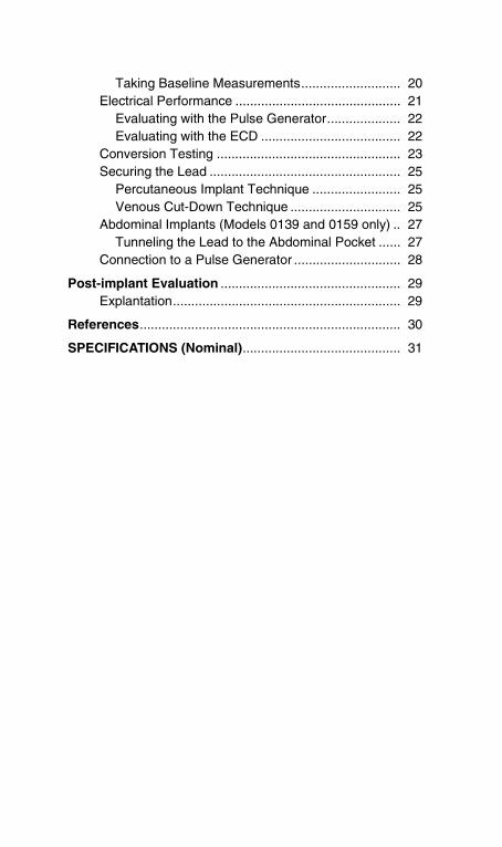
1
EN
DO
TAK
RE
LIA
NC
E S
Lea
d,
Mod
els
0137
/013
8/01
39
EN
DO
TAK
RE
LIA
NC
E L
ead,
M
odel
s 01
57/0
158/
0159
1.D
ista
l ste
roid
-elu
ting
pace
/sen
se e
lect
rode
(cat
hode
)
2.P
roxi
mal
pac
e/se
nse
coil
elec
trod
e (a
node
), di
stal
de
fibril
latin
g co
il el
ectro
de
3.P
roxi
mal
def
ibril
latin
g co
il el
ectro
de–
EN
DO
TAK
RE
LIA
NC
E o
nly
4.S
utur
e S
leev
e
5.S
econ
d S
utur
e S
leev
e-M
odel
s 01
39 a
nd 0
159
only
6.Yo
ke
7.D
ista
l def
ibril
latin
g el
ectr
ode
term
inal
(cat
hode
)
8.P
roxi
mal
and
dis
tal p
ace/
sens
e el
ectro
de te
rmin
al
9.P
roxi
mal
def
ibril
latin
g el
ectro
de te
rmin
al (
anod
e)
EN
DO
TAK
RE
LIA
NC
E o
nly
2
8
9
3554
58_2
.boo
k P
age
35 M
onda
y, M
arch
4, 2
002
5:0
7 PM
CONTENTS
355458_2.book Page 36 Monday, March 4, 2002 5:07 PM
Device Description............................................................ 1Indications for Use...................................................... 1Contraindications........................................................ 1Warnings .................................................................... 1
AICD/Lead Compatibility ........................................ 2Implantation ........................................................... 2Electrical Performance ........................................... 2Conversion Testing ................................................ 3Securing and Tunneling ......................................... 3
Precautions ................................................................ 3Observed Adverse Events.......................................... 3
Potential Adverse Events ....................................... 4Warranty..................................................................... 5
Lead Features.................................................................... 6
Lead Evaluation ................................................................ 8Implant Information..................................................... 8Opening Instructions .................................................. 9Sterilization................................................................. 9Surgical Preparation................................................... 9Accessories .............................................................. 10
Suture Sleeves..................................................... 10Fixation Tool ........................................................ 10Stylets .................................................................. 10Stylet Guide ......................................................... 11Vein Pick .............................................................. 11Lead Caps............................................................ 11
Handling the Lead .................................................... 12
Implantation..................................................................... 12Inserting the Stylet.................................................... 12Handling the Fixation Helix....................................... 13Inserting the Lead..................................................... 14Positioning the Lead................................................. 16Lead Fixation............................................................ 17Checking for Lead Stability....................................... 19Repositioning the Lead............................................. 19Evaluating Lead Position.......................................... 20
Minimizing Pacemaker Interaction ....................... 20
355458_2.book Page 37 Monday, March 4, 2002 5:07 PM
Taking Baseline Measurements........................... 20Electrical Performance ............................................. 21
Evaluating with the Pulse Generator.................... 22Evaluating with the ECD ...................................... 22
Conversion Testing .................................................. 23Securing the Lead .................................................... 25
Percutaneous Implant Technique ........................ 25Venous Cut-Down Technique .............................. 25
Abdominal Implants (Models 0139 and 0159 only) .. 27Tunneling the Lead to the Abdominal Pocket ...... 27
Connection to a Pulse Generator ............................. 28
Post-implant Evaluation ................................................. 29Explantation.............................................................. 29
References....................................................................... 30
SPECIFICATIONS (Nominal)........................................... 31
DEVICE DESCRIPTION 1
355458-001 RELIANCE/S active US355458_2.book Page 1 Monday, March 4, 2002 5:07 PM
DEVICE DESCRIPTION
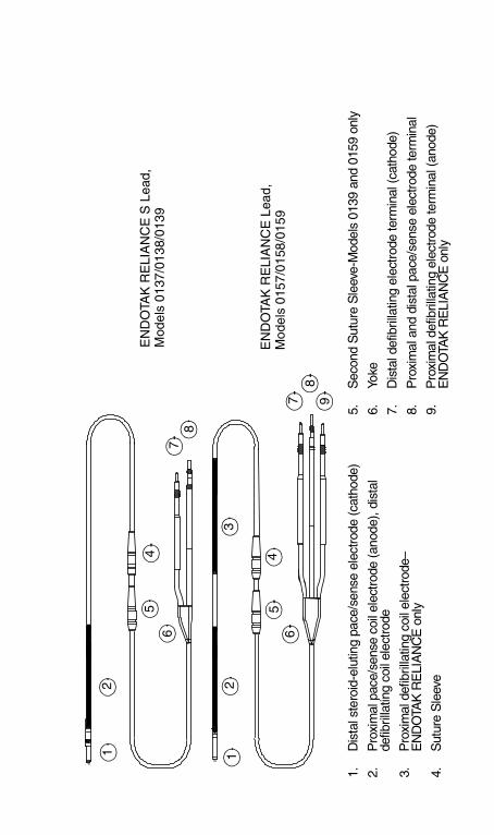
The ENDOTAK RELIANCE lead, Models 0157/0158/0159, and the ENDOTAK RELIANCE S lead, Models 0137/0138/0139, are active fixation, endocardial cardioversion/defibrillation, and pace/sense leads with an extendable/retractable helix and a steroid-eluting collar. The silicone lead body has a lubricious coating. The ENDOTAK RELIANCE (dual-coil leads) and the ENDOTAK RELIANCE S (single-coil leads) are for use as an integral part of an AICD automatic implantable cardioverter defibrillator system with DF-11 and IS-12 ports.
Instructions in this manual should be used in conjunction with other resource material, including the applicable AICD physician’s manual, the applicable VENTAK External Cardioverter Defibrillator (ECD) user’s manual, the ENDOTAK SQ Array lead physician’s manual, and the AICD Y Connector product data sheet.
Indications for UseThe ENDOTAK RELIANCE lead, Models 0157/0158/0159, and the ENDOTAK RELIANCE S lead, Models 0137/0138/0139 provide pacing and rate-sensing and deliver cardioversion and defibrillation shocks for AICD automatic implantable cardioverter defibrillator systems.
ContraindicationsUse of the ENDOTAK RELIANCE and ENDOTAK RELIANCE S active fixation lead is contraindicated for the following patients:
• Patients who have a unipolar pacemaker.
• Patients with a hypersensitivity to a nominal single dose of 1.0 mg dexamethasone acetate.
• Patients with tricuspid valvular disease.
• Patients with mechanical tricuspid heart valves.
WarningsIn the following list of warnings, page numbers are indicated for those warnings that are specific to other areas of the manual. Refer to the indicated pages for information relevant to the warning.
DEVICE DESCRIPTION2
355458-001 RELIANCE/S active US355458_2.book Page 2 Monday, March 4, 2002 5:07 PM
AICD/Lead Compatibility
• Do not attempt to use the ENDOTAK lead system with any device other than a commercially available implantable defibrillator system with which it has been tested and demonstrated to be safe and effective. The potential adverse consequences of using a combination that has not been tested and demonstrated to be safe and effective may include, but are not limited to, undersensing cardiac activity and failure to deliver necessary therapy.
Implantation
• The safety and efficacy of the tip electrode placement above midseptum has not been clinically established.
• Lead fracture, dislodgment, abrasion and/or an incomplete connection can cause a periodic or continual loss of rate-sensing, possibly resulting in arrhythmia nondetection; or over-sensing of rate, possibly resulting in inappropriate delivery of a pulse generator shock; or inadequate delivery of converting energy.
• Although pliable, the lead is not designed to tolerate excessive flexing, bending, or tension. This could cause structural weakness, conductor discontinuity, and/or lead dislodgment. (Page 12)
• Take care to obtain appropriate electrode position. Failure to do so may result in higher defibrillation thresholds or may render the lead unable to defibrillate a patient whose tachyarrhythmia(s) might otherwise be convertible by an AICD system. (Page 17)
• In order to deliver defibrillation therapy, the single-coil ENDOTAK RELIANCE S lead must be implanted with a separate defibrillation electrode. Guidant recommends using the ENDOTAK RELIANCE S lead with a pectorally implanted device that uses the metallic housing as a defibrillation electrode. (Page 17)
Electrical Performance
• When connecting the lead to ECD cables, and/or later to the AICD pulse generator, it is very important that proper connections are made. Damage to the heart could result if a high-voltage defibrillating pulse were to be delivered through the pace/sense tip electrode. (Page 21)
DEVICE DESCRIPTION 3
355458-001 RELIANCE/S active US355458_2.book Page 3 Monday, March 4, 2002 5:07 PM
Conversion Testing
• Use of any component of the ENDOTAK lead system to assist in delivery of external-source rescue shocks could cause extensive tissue damage. (Page 24)
Securing and Tunneling
• Do not kink, twist, or braid the lead terminals as doing so could cause lead insulation abrasion damage. (Page 26)
Precautions • The lead and its accessories are intended only for one-time
use. Do not reuse.
• It has not been determined whether the warnings, precautions, or complications usually associated with injectable dexamethasone acetate apply to the use of the low concentration, highly localized, controlled-release device. For a listing of potentially adverse effects, refer to the Physician’s Desk Reference.
• Refer to the Implant Information, Implantation and Post-implant Evaluation sections of this manual for cautions specific to handling, implanting, and testing the ENDOTAK RELIANCE lead family. Failure to observe these cautions could result in incorrect lead implantation, lead damage, and/or harm to the patient.
Adverse Events
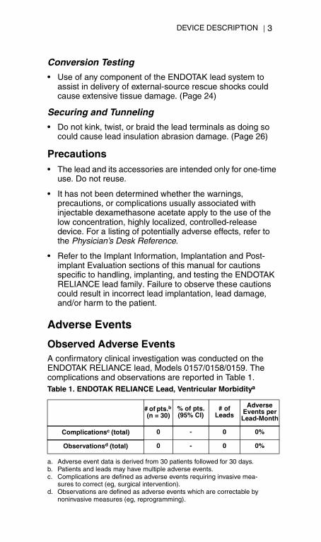
Observed Adverse EventsA confirmatory clinical investigation was conducted on the ENDOTAK RELIANCE lead, Models 0157/0158/0159. The complications and observations are reported in Table 1.Table 1. ENDOTAK RELIANCE Lead, Ventricular Morbiditya
a. Adverse event data is derived from 30 patients followed for 30 days.
# of pts.b (n = 30)
b. Patients and leads may have multiple adverse events.
% of pts. (95% CI)
# of Leads
Adverse Events per Lead-Month
Complicationsc (total)
c. Complications are defined as adverse events requiring invasive mea-sures to correct (eg, surgical intervention).
0 - 0 0%
Observationsd (total)
d. Observations are defined as adverse events which are correctable by noninvasive measures (eg, reprogramming).
0 - 0 0%
DEVICE DESCRIPTION4
355458-001 RELIANCE/S active US355458_2.book Page 4 Monday, March 4, 2002 5:07 PM
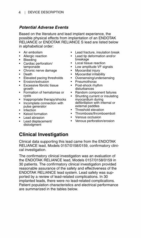
Potential Adverse Events
Based on the literature and lead implant experience, the possible physical effects from implantation of an ENDOTAK RELIANCE or ENDOTAK RELIANCE S lead are listed below in alphabetical order:
Clinical InvestigationClinical data supporting this lead came from the ENDOTAK RELIANCE lead, Models 0157/0158/0159, confirmatory clini-cal investigation.
The confirmatory clinical investigation was an evaluation of the ENDOTAK RELIANCE lead, Models 0157/0158/0159 in 30 patients. The confirmatory clinical investigation provided reasonable assurance of the safety and effectiveness of the ENDOTAK RELIANCE lead system. Lead safety was sup-ported by a review of lead-related complications. In 30 implanted leads, there were no lead-related complications. Patient population characteristics and electrical performance are summarized in the tables below.
• Air embolism• Allergic reaction• Bleeding• Cardiac perforation/
tamponade• Chronic nerve damage• Death• Elevated pacing thresholds• Erosion/extrusion• Excessive fibrotic tissue
growth• Formation of hematomas or
cysts• Inappropriate therapy/shocks• Incomplete connection with
pulse generator• Infection• Keloid formation• Lead abrasion• Lead displacement/
dislodgment
• Lead fracture, insulation break• Lead tip deformation and/or
breakage• Local tissue reaction• Low amplitude VF signals• Myocardial injury• Myocardial irritability• Oversensing/undersensing• Pneumothorax• Post-shock rhythm
disturbances• Random component failures• Shunting current or insulating
myocardium during defibrillation with internal or external paddles
• Threshold elevation• Thrombosis/thromboemboli• Venous occlusion• Venous perforation/erosion
DEVICE DESCRIPTION 5
355458-001 RELIANCE/S active US355458_2.book Page 5 Monday, March 4, 2002 5:07 PM
WarrantySee the enclosed Lead Information card for warranty information. For additional copies, please contact Guidant Corporation at the address on the back cover.
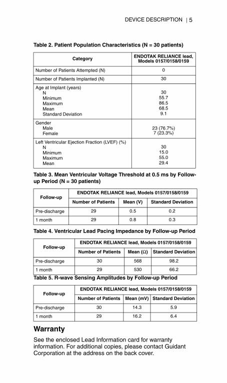
Table 2. Patient Population Characteristics (N = 30 patients)
Category ENDOTAK RELIANCE lead, Models 0157/0158/0159
Number of Patients Attempted (N) 0
Number of Patients Implanted (N) 30
Age at Implant (years)NMinimumMaximumMeanStandard Deviation
3055.786.568.59.1
GenderMaleFemale
23 (76.7%)7 (23.3%)
Left Ventricular Ejection Fraction (LVEF) (%)NMinimumMaximumMean
3015.055.029.4
Table 3. Mean Ventricular Voltage Threshold at 0.5 ms by Follow-up Period (N = 30 patients)
Follow-upENDOTAK RELIANCE lead, Models 0157/0158/0159
Number of Patients Mean (V) Standard Deviation
Pre-discharge 29 0.5 0.2
1 month 29 0.8 0.3
Table 4. Ventricular Lead Pacing Impedance by Follow-up Period
Follow-upENDOTAK RELIANCE lead, Models 0157/0158/0159
Number of Patients Mean (Ω) Standard Deviation
Pre-discharge 30 568 98.2
1 month 29 530 66.2
Table 5. R-wave Sensing Amplitudes by Follow-up Period
Follow-upENDOTAK RELIANCE lead, Models 0157/0158/0159
Number of Patients Mean (mV) Standard Deviation
Pre-discharge 30 14.3 5.9
1 month 29 16.2 6.4
LEAD FEATURES6
355458-001 RELIANCE/S active US355458_2.book Page 6 Monday, March 4, 2002 5:07 PM
Refer to the Contraindications, Warnings, Precautions, and Adverse Events sections of this manual for information concerning the performance of this device.
LEAD FEATURESFeatures of the ENDOTAK RELIANCE and ENDOTAK RELIANCE S active fixation lead include the following components:
• Steroid Distal Tip: The tip electrode contains a nominal dose of 1.0 mg dexamethasone acetate within a silicone collar. Upon exposure to body fluids, the steroid elutes from the external collar. Steroid suppresses the inflammatory response believed to cause threshold rises typically associated with implanted pacing electrodes. Lower thresholds are desirable because they can increase pacing safety margins and reduce pacing energy requirements, potentially increasing pulse generator longevity.
• Extendable/Retractable Fixation Helix: The extendable/ retractable helix design anchors the distal tip electrode to the endocardial surface without support of trabecular structures, offering various lead placement possibilities for the tip electrode. The extendable/retractable helix serves as the cathode for intracardiac right ventricular electrogram rate sensing and pacing. The helix is extended/retracted using a terminal pin mechanism.
• Fluoroscopic Markers: The lead has radiopaque markers near the distal tip that can be seen under fluoroscopy. These markers show when the helix is fully retracted or fully extended.
• Coil Electrodes: The distal coil electrode is intended to serve as an anode for rate-sensing and pacing and as an anode or cathode for cardioversion/defibrillation shocks. The proximal coil electrode on the ENDOTAK RELIANCE lead is intended to serve as an anode or cathode for cardioversion/defibrillation shocks. The ENDOTAK RELIANCE lead family uses the implanted device metallic housing as an additional defibrillation electrode.
• Lead Body: The isodiametric lead body contains one conductor for pacing/sensing. The ENDOTAK RELIANCE lead has two conductors for defibrillation and the ENDOTAK RELIANCE S lead has one conductor for defibrillation. The conductors are coated with PTFE and
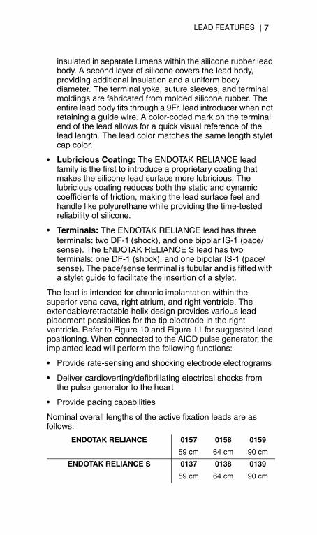
LEAD FEATURES 7
355458-001 RELIANCE/S active US355458_2.book Page 7 Monday, March 4, 2002 5:07 PM
insulated in separate lumens within the silicone rubber lead body. A second layer of silicone covers the lead body, providing additional insulation and a uniform body diameter. The terminal yoke, suture sleeves, and terminal moldings are fabricated from molded silicone rubber. The entire lead body fits through a 9Fr. lead introducer when not retaining a guide wire. A color-coded mark on the terminal end of the lead allows for a quick visual reference of the lead length. The lead color matches the same length stylet cap color.
• Lubricious Coating: The ENDOTAK RELIANCE lead family is the first to introduce a proprietary coating that makes the silicone lead surface more lubricious. The lubricious coating reduces both the static and dynamic coefficients of friction, making the lead surface feel and handle like polyurethane while providing the time-tested reliability of silicone.
• Terminals: The ENDOTAK RELIANCE lead has three terminals: two DF-1 (shock), and one bipolar IS-1 (pace/sense). The ENDOTAK RELIANCE S lead has two terminals: one DF-1 (shock), and one bipolar IS-1 (pace/sense). The pace/sense terminal is tubular and is fitted with a stylet guide to facilitate the insertion of a stylet.
The lead is intended for chronic implantation within the superior vena cava, right atrium, and right ventricle. The extendable/retractable helix design provides various lead placement possibilities for the tip electrode in the right ventricle. Refer to Figure 10 and Figure 11 for suggested lead positioning. When connected to the AICD pulse generator, the implanted lead will perform the following functions:
• Provide rate-sensing and shocking electrode electrograms
• Deliver cardioverting/defibrillating electrical shocks from the pulse generator to the heart
• Provide pacing capabilities
Nominal overall lengths of the active fixation leads are as follows:
ENDOTAK RELIANCE 0157 0158 0159
59 cm 64 cm 90 cm
ENDOTAK RELIANCE S 0137 0138 0139
59 cm 64 cm 90 cm
LEAD EVALUATION8
355458-001 RELIANCE/S active US355458_2.book Page 8 Monday, March 4, 2002 5:07 PM
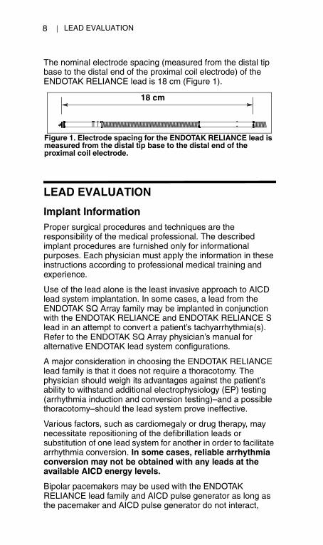
The nominal electrode spacing (measured from the distal tip base to the distal end of the proximal coil electrode) of the ENDOTAK RELIANCE lead is 18 cm (Figure 1).
LEAD EVALUATION
Implant InformationProper surgical procedures and techniques are the responsibility of the medical professional. The described implant procedures are furnished only for informational purposes. Each physician must apply the information in these instructions according to professional medical training and experience.
Use of the lead alone is the least invasive approach to AICD lead system implantation. In some cases, a lead from the ENDOTAK SQ Array family may be implanted in conjunction with the ENDOTAK RELIANCE and ENDOTAK RELIANCE S lead in an attempt to convert a patient’s tachyarrhythmia(s). Refer to the ENDOTAK SQ Array physician’s manual for alternative ENDOTAK lead system configurations.
A major consideration in choosing the ENDOTAK RELIANCE lead family is that it does not require a thoracotomy. The physician should weigh its advantages against the patient’s ability to withstand additional electrophysiology (EP) testing (arrhythmia induction and conversion testing)–and a possible thoracotomy–should the lead system prove ineffective.
Various factors, such as cardiomegaly or drug therapy, may necessitate repositioning of the defibrillation leads or substitution of one lead system for another in order to facilitate arrhythmia conversion. In some cases, reliable arrhythmia conversion may not be obtained with any leads at the available AICD energy levels.
Bipolar pacemakers may be used with the ENDOTAK RELIANCE lead family and AICD pulse generator as long as the pacemaker and AICD pulse generator do not interact,
Figure 1. Electrode spacing for the ENDOTAK RELIANCE lead is measured from the distal tip base to the distal end of the proximal coil electrode.
18 cm
LEAD EVALUATION 9
355458-001 RELIANCE/S active US355458_2.book Page 9 Monday, March 4, 2002 5:07 PM
causing AICD pulse generator nondetection or false detection. Refer to the section, Minimizing Pacemaker Interaction on Page 20 for more information.
The lead is not designed, sold, or intended for use except as indicated.
The following items are packaged with the ENDOTAK RELIANCE and ENDOTAK RELIANCE S active fixation lead:
Opening Instructions
The outer package and sterile tray may be opened by authorized personnel under clean conditions. To ensure sterility, the sealed inner sterile tray must be opened using accepted aseptic technique by scrubbed, masked, sterile-gowned personnel. The sterile tray is opened by peeling back the cover.
SterilizationGuidant sterilizes the lead and accessories with ethylene oxide gas (EtO) before final packaging. When they are received, they are sterile and ready for use. If the container is wet, damaged, punctured, or if the seal is broken, return the lead to the nearest Guidant representative. Never attempt to resterilize the lead.
Surgical PreparationInstrumentation for cardiac monitoring, imaging (fluoroscopy), defibrillation, and lead signal measurements must be available during implant. When using electrical instrumentation, electrically isolate the patient from potentially hazardous current leakage. Guidant also recommends availability of
• Straight stylets, softa
a. Green knobs, 0.014-in (0.36-mm) diameter
• Straight stylets, firmb
b. White knobs, 0.016-in (0.41-mm) diameter
• Fixation tools• Stylet guide• Vein pick• Lead caps, (2) DF-1 and (1) IS-1• DF-1 port plugs (ENDOTAK RELIANCE S lead only)• Literature packet
LEAD EVALUATION10
355458-001 RELIANCE/S active US355458_2.book Page 10 Monday, March 4, 2002 5:07 PM
sterile duplicates of all implantable items in case of accidental damage or contamination.
Accessories
Suture Sleeves
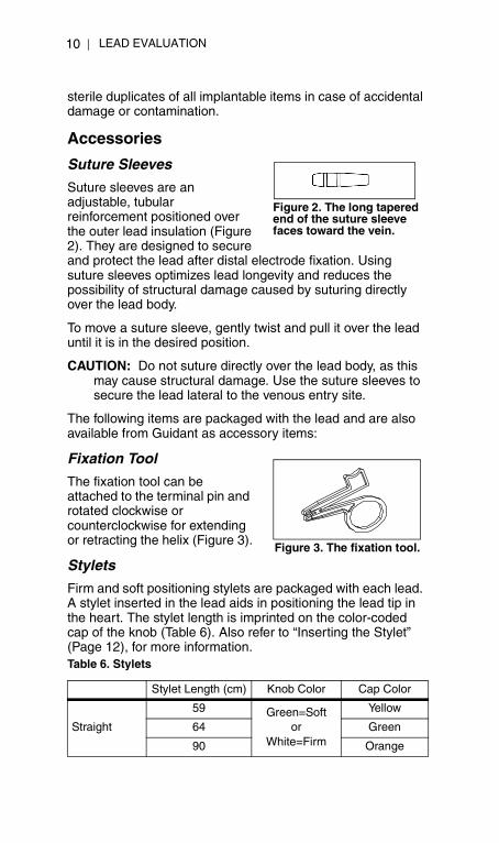
Suture sleeves are an adjustable, tubular reinforcement positioned over the outer lead insulation (Figure 2). They are designed to secure and protect the lead after distal electrode fixation. Using suture sleeves optimizes lead longevity and reduces the possibility of structural damage caused by suturing directly over the lead body.
To move a suture sleeve, gently twist and pull it over the lead until it is in the desired position.
CAUTION: Do not suture directly over the lead body, as this may cause structural damage. Use the suture sleeves to secure the lead lateral to the venous entry site.
The following items are packaged with the lead and are also available from Guidant as accessory items:
Fixation Tool
The fixation tool can be attached to the terminal pin and rotated clockwise or counterclockwise for extending or retracting the helix (Figure 3).
Stylets
Firm and soft positioning stylets are packaged with each lead. A stylet inserted in the lead aids in positioning the lead tip in the heart. The stylet length is imprinted on the color-coded cap of the knob (Table 6). Also refer to “Inserting the Stylet” (Page 12), for more information.Table 6. Stylets
Stylet Length (cm) Knob Color Cap Color
Straight
59 Green=Softor
White=Firm
Yellow
64 Green
90 Orange
Figure 2. The long tapered end of the suture sleeve faces toward the vein.
Figure 3. The fixation tool.
LEAD EVALUATION 11
355458-001 RELIANCE/S active US355458_2.book Page 11 Monday, March 4, 2002 5:07 PM
Stylet Guide
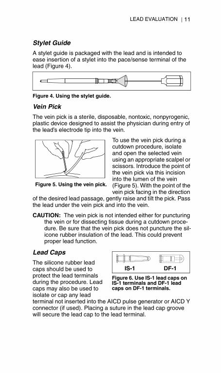
A stylet guide is packaged with the lead and is intended to ease insertion of a stylet into the pace/sense terminal of the lead (Figure 4).
Vein Pick
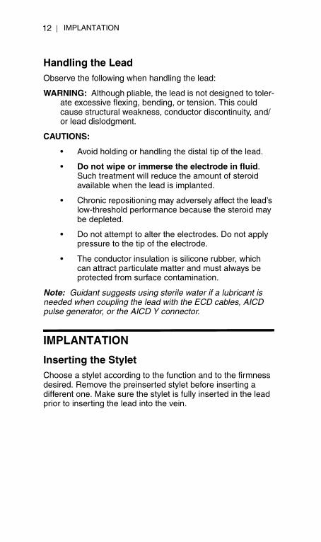
The vein pick is a sterile, disposable, nontoxic, nonpyrogenic, plastic device designed to assist the physician during entry of the lead’s electrode tip into the vein.
To use the vein pick during a cutdown procedure, isolate and open the selected vein using an appropriate scalpel or scissors. Introduce the point of the vein pick via this incision into the lumen of the vein (Figure 5). With the point of the vein pick facing in the direction
of the desired lead passage, gently raise and tilt the pick. Pass the lead under the vein pick and into the vein.
CAUTION: The vein pick is not intended either for puncturing the vein or for dissecting tissue during a cutdown proce-dure. Be sure that the vein pick does not puncture the sil-icone rubber insulation of the lead. This could prevent proper lead function.
Lead Caps
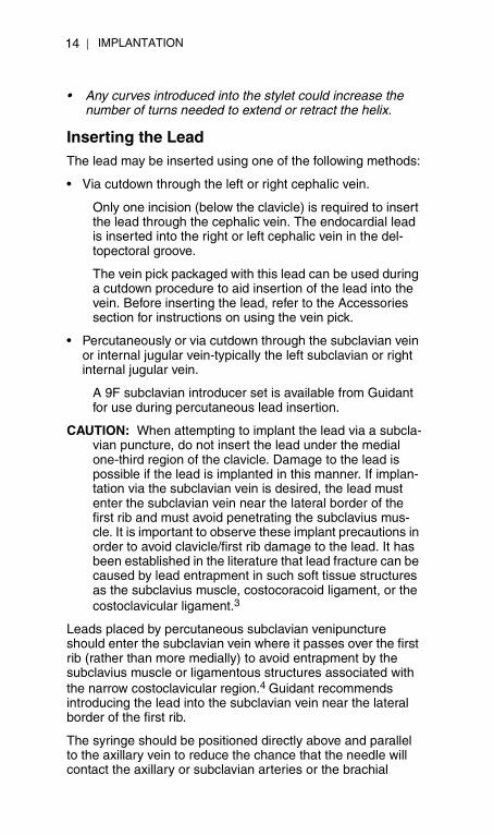
The silicone rubber lead caps should be used to protect the lead terminals during the procedure. Lead caps may also be used to isolate or cap any lead terminal not inserted into the AICD pulse generator or AICD Y connector (if used). Placing a suture in the lead cap groove will secure the lead cap to the lead terminal.
Figure 4. Using the stylet guide.
Figure 5. Using the vein pick.
Figure 6. Use IS-1 lead caps on IS-1 terminals and DF-1 lead caps on DF-1 terminals.
IS-1 DF-1
IMPLANTATION12
355458-001 RELIANCE/S active US355458_2.book Page 12 Monday, March 4, 2002 5:07 PM
Handling the LeadObserve the following when handling the lead:
WARNING: Although pliable, the lead is not designed to toler-ate excessive flexing, bending, or tension. This could cause structural weakness, conductor discontinuity, and/or lead dislodgment.
CAUTIONS:
• Avoid holding or handling the distal tip of the lead.
• Do not wipe or immerse the electrode in fluid. Such treatment will reduce the amount of steroid available when the lead is implanted.
• Chronic repositioning may adversely affect the lead’s low-threshold performance because the steroid may be depleted.
• Do not attempt to alter the electrodes. Do not apply pressure to the tip of the electrode.
• The conductor insulation is silicone rubber, which can attract particulate matter and must always be protected from surface contamination.
Note: Guidant suggests using sterile water if a lubricant is needed when coupling the lead with the ECD cables, AICD pulse generator, or the AICD Y connector.
IMPLANTATION
Inserting the StyletChoose a stylet according to the function and to the firmness desired. Remove the preinserted stylet before inserting a different one. Make sure the stylet is fully inserted in the lead prior to inserting the lead into the vein.

IMPLANTATION 13
355458-001 RELIANCE/S active US355458_2.book Page 13 Monday, March 4, 2002 5:07 PM
Gently curve the preferred straight stylet with any sterile, smooth-surfaced instrument (eg, 10- or 12-cc syringe barrel) (Figure 7) and carefully insert the stylet through the lumen of the conductor. A sharp bend in the stylet may straighten as it passes through the lumen of the terminal pin. A gentle curve is less likely to straighten.
CAUTION: Do not bend the lead with a stylet in place. Bend-ing the lead could damage the conductor and insulation material.
Note: To optimize insertion into the lead, do not allow body fluids to come in contact with the stylet.
Handling the Fixation HelixBefore implanting the lead, verify the mechanical functioning of the lead by rotating the terminal pin and visually observing the helix extending and retracting. The helix can be extended or retracted by rotating the terminal pin clockwise to extend the helix or counterclockwise to retract it.
Note: Refer to the Lead Fixation section on Page 17 for addi-tional information on how to fixate the helix and to the Specifi-cations section on Page 31 for the expected and maximum number of turns to extend or retract the helix.
CAUTIONS:
• Do not overextend or overretract the helix. Continuing to rotate the terminal pin once the helix is fully extended or retracted can damage the lead.
• If the helix cannot be extended or retracted, do not use the lead.
• Do not alter the electrodes or use a lead with a deformed helix or damaged helix fixation mechanism. Do not attempt to straighten or realign the fixation helix.
Notes: • Do not insert a lead into the vein when the helix is
extended. Rotate the terminal pin counterclockwise to retract the helix into the distal lead tip prior to insertion into the vein.
Figure 7. Curve the stylet.
Syringe
6 cm
70°-90°
IMPLANTATION14
355458-001 RELIANCE/S active US355458_2.book Page 14 Monday, March 4, 2002 5:07 PM
• Any curves introduced into the stylet could increase the number of turns needed to extend or retract the helix.
Inserting the LeadThe lead may be inserted using one of the following methods:
• Via cutdown through the left or right cephalic vein.
Only one incision (below the clavicle) is required to insert the lead through the cephalic vein. The endocardial lead is inserted into the right or left cephalic vein in the del-topectoral groove.
The vein pick packaged with this lead can be used during a cutdown procedure to aid insertion of the lead into the vein. Before inserting the lead, refer to the Accessories section for instructions on using the vein pick.
• Percutaneously or via cutdown through the subclavian vein or internal jugular vein-typically the left subclavian or right internal jugular vein.
A 9F subclavian introducer set is available from Guidant for use during percutaneous lead insertion.
CAUTION: When attempting to implant the lead via a subcla-vian puncture, do not insert the lead under the medial one-third region of the clavicle. Damage to the lead is possible if the lead is implanted in this manner. If implan-tation via the subclavian vein is desired, the lead must enter the subclavian vein near the lateral border of the first rib and must avoid penetrating the subclavius mus-cle. It is important to observe these implant precautions in order to avoid clavicle/first rib damage to the lead. It has been established in the literature that lead fracture can be caused by lead entrapment in such soft tissue structures as the subclavius muscle, costocoracoid ligament, or the costoclavicular ligament.3
Leads placed by percutaneous subclavian venipuncture should enter the subclavian vein where it passes over the first rib (rather than more medially) to avoid entrapment by the subclavius muscle or ligamentous structures associated with the narrow costoclavicular region.4 Guidant recommends introducing the lead into the subclavian vein near the lateral border of the first rib.
The syringe should be positioned directly above and parallel to the axillary vein to reduce the chance that the needle will contact the axillary or subclavian arteries or the brachial
IMPLANTATION 15
355458-001 RELIANCE/S active US355458_2.book Page 15 Monday, March 4, 2002 5:07 PM
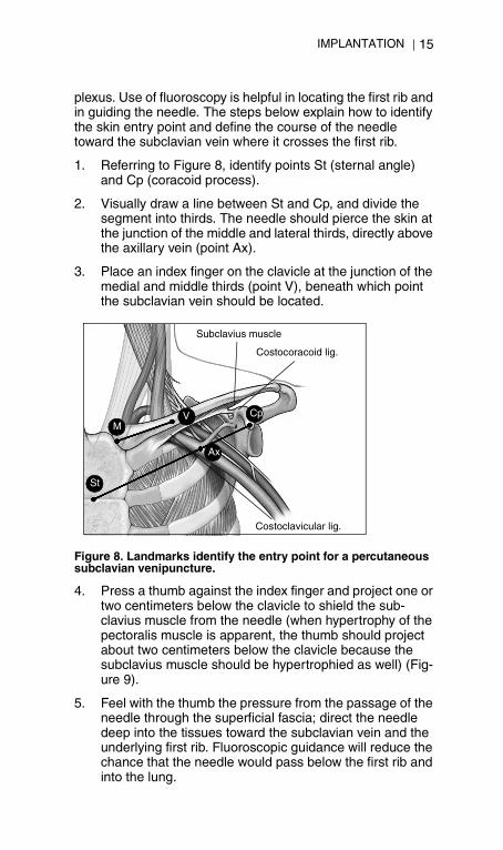
plexus. Use of fluoroscopy is helpful in locating the first rib and in guiding the needle. The steps below explain how to identify the skin entry point and define the course of the needle toward the subclavian vein where it crosses the first rib.
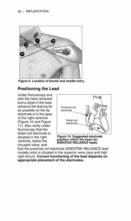
1. Referring to Figure 8, identify points St (sternal angle) and Cp (coracoid process).
2. Visually draw a line between St and Cp, and divide the segment into thirds. The needle should pierce the skin at the junction of the middle and lateral thirds, directly above the axillary vein (point Ax).
3. Place an index finger on the clavicle at the junction of the medial and middle thirds (point V), beneath which point the subclavian vein should be located.
4. Press a thumb against the index finger and project one or two centimeters below the clavicle to shield the sub-clavius muscle from the needle (when hypertrophy of the pectoralis muscle is apparent, the thumb should project about two centimeters below the clavicle because the subclavius muscle should be hypertrophied as well) (Fig-ure 9).
5. Feel with the thumb the pressure from the passage of the needle through the superficial fascia; direct the needle deep into the tissues toward the subclavian vein and the underlying first rib. Fluoroscopic guidance will reduce the chance that the needle would pass below the first rib and into the lung.
Figure 8. Landmarks identify the entry point for a percutaneous subclavian venipuncture.
Subclavius muscle
Costoclavicular lig.
Costocoracoid lig.
St
MV Cp
Ax
IMPLANTATION16
355458-001 RELIANCE/S active US355458_2.book Page 16 Monday, March 4, 2002 5:07 PM
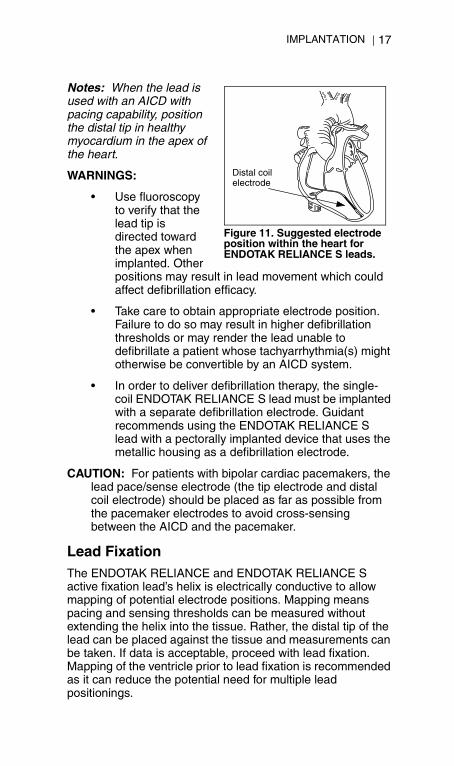
Positioning the LeadUnder fluoroscopy and with the helix retracted and a stylet in the lead, advance the lead as far as possible so the tip electrode is in the apex of the right ventricle (Figure 10 and Figure 11). Also verify under fluoroscopy that the distal coil electrode is situated in the right ventricle, below the tricuspid valve, and that the proximal coil electrode (ENDOTAK RELIANCE lead models only) is situated in the superior vena cava and high right atrium. Correct functioning of the lead depends on appropriate placement of the electrodes.
Figure 9. Location of thumb and needle entry.
St
MV Cp
Figure 10. Suggested electrode position within the heart for ENDOTAK RELIANCE leads.
Proximal coil electrode
Distal coil electrode
IMPLANTATION 17
355458-001 RELIANCE/S active US355458_2.book Page 17 Monday, March 4, 2002 5:07 PM
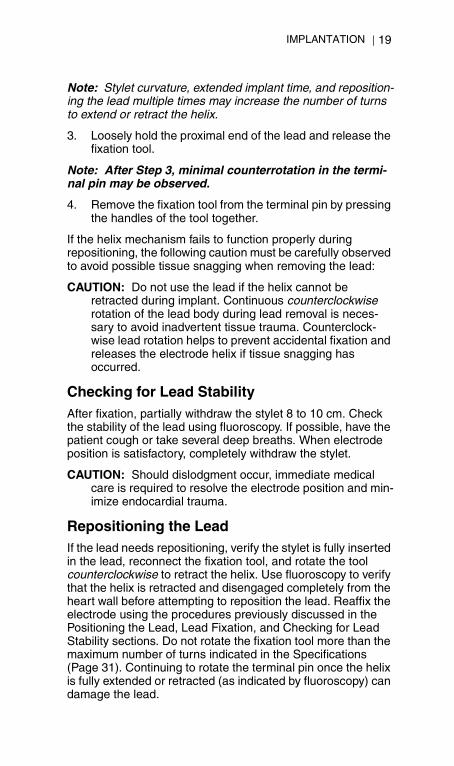
Notes: When the lead is used with an AICD with pacing capability, position the distal tip in healthy myocardium in the apex of the heart.
WARNINGS:
• Use fluoroscopy to verify that the lead tip is directed toward the apex when implanted. Other positions may result in lead movement which could affect defibrillation efficacy.
• Take care to obtain appropriate electrode position. Failure to do so may result in higher defibrillation thresholds or may render the lead unable to defibrillate a patient whose tachyarrhythmia(s) might otherwise be convertible by an AICD system.
• In order to deliver defibrillation therapy, the single-coil ENDOTAK RELIANCE S lead must be implanted with a separate defibrillation electrode. Guidant recommends using the ENDOTAK RELIANCE S lead with a pectorally implanted device that uses the metallic housing as a defibrillation electrode.
CAUTION: For patients with bipolar cardiac pacemakers, the lead pace/sense electrode (the tip electrode and distal coil electrode) should be placed as far as possible from the pacemaker electrodes to avoid cross-sensing between the AICD and the pacemaker.
Lead FixationThe ENDOTAK RELIANCE and ENDOTAK RELIANCE S active fixation lead’s helix is electrically conductive to allow mapping of potential electrode positions. Mapping means pacing and sensing thresholds can be measured without extending the helix into the tissue. Rather, the distal tip of the lead can be placed against the tissue and measurements can be taken. If data is acceptable, proceed with lead fixation. Mapping of the ventricle prior to lead fixation is recommended as it can reduce the potential need for multiple lead positionings.
Figure 11. Suggested electrode position within the heart for ENDOTAK RELIANCE S leads.
Distal coil electrode

IMPLANTATION18
355458-001 RELIANCE/S active US355458_2.book Page 18 Monday, March 4, 2002 5:07 PM
Note: The stylet must be fully inserted during fixation or repo-sitioning.
1. When the correct position has been achieved, attach the fixation tool to the ter-minal pin. Press the han-dles together and place the pin in the preformed groove. Release the ten-sion on the handles to secure the terminal pin in the fixation tool (Figure 12).
2. Apply forward pressure to the lead body to position the distal electrode against the desired fixation site and rotate the fixation tool clockwise to affix the distal electrode helix into the heart wall. View the radiopaque markers under fluoroscopy to identify when the fixation helix is fully extended. Full extension is achieved when the radio-paque markers are joined and the fixation helix is extended outside the distal fluoroscopy markers (Figure 13). Refer to the Specifications section on Page 31 for the expected number of turns to extend or retract the helix.
CAUTION: Do not rotate the terminal pin clockwise more than the maximum number of turns indicated for each model number in the Specification section on Page 31. Continu-ing to rotate the terminal pin once the helix is fully extended or retracted (as indicated by fluoroscopy) can damage the lead, cause lead dislodgment, and/or cause acute pacing threshold to rise.
Figure 13. Possible views of the helix electrode.
Figure 12. Attaching and rotating the fixation tool.
FluoroscopicFluoroscopic
Visual Visual
FULLY RETRACTED FULLY EXTENDED
IMPLANTATION 19
355458-001 RELIANCE/S active US355458_2.book Page 19 Monday, March 4, 2002 5:07 PM
Note: Stylet curvature, extended implant time, and reposition-ing the lead multiple times may increase the number of turns to extend or retract the helix.
3. Loosely hold the proximal end of the lead and release the fixation tool.
Note: After Step 3, minimal counterrotation in the termi-nal pin may be observed.
4. Remove the fixation tool from the terminal pin by pressing the handles of the tool together.
If the helix mechanism fails to function properly during repositioning, the following caution must be carefully observed to avoid possible tissue snagging when removing the lead:
CAUTION: Do not use the lead if the helix cannot be retracted during implant. Continuous counterclockwise rotation of the lead body during lead removal is neces-sary to avoid inadvertent tissue trauma. Counterclock-wise lead rotation helps to prevent accidental fixation and releases the electrode helix if tissue snagging has occurred.
Checking for Lead StabilityAfter fixation, partially withdraw the stylet 8 to 10 cm. Check the stability of the lead using fluoroscopy. If possible, have the patient cough or take several deep breaths. When electrode position is satisfactory, completely withdraw the stylet.
CAUTION: Should dislodgment occur, immediate medical care is required to resolve the electrode position and min-imize endocardial trauma.
Repositioning the LeadIf the lead needs repositioning, verify the stylet is fully inserted in the lead, reconnect the fixation tool, and rotate the tool counterclockwise to retract the helix. Use fluoroscopy to verify that the helix is retracted and disengaged completely from the heart wall before attempting to reposition the lead. Reaffix the electrode using the procedures previously discussed in the Positioning the Lead, Lead Fixation, and Checking for Lead Stability sections. Do not rotate the fixation tool more than the maximum number of turns indicated in the Specifications (Page 31). Continuing to rotate the terminal pin once the helix is fully extended or retracted (as indicated by fluoroscopy) can damage the lead.
IMPLANTATION20
355458-001 RELIANCE/S active US355458_2.book Page 20 Monday, March 4, 2002 5:07 PM
Evaluating Lead PositionVerify electrical performance of the lead before attaching the lead to the pulse generator or a Guidant ECD and after allowing sufficient time for the effect of local tissue trauma to subside. The use of radiography or fluoroscopy during the operation may help ensure lead position and integrity. If testing results are unsatisfactory, lead system repositioning or replacement may be required.
Minimizing Pacemaker Interaction
To minimize potential interaction between a permanent pacemaker and an AICD pulse generator, consider the following:5, 6
• After implanting the pacing leads, examine the signals from the pace/sense electrodes to ensure that minimal pacemaker artifacts are present. (Use a recording system that has a bandwidth of at least 2000 Hz to ensure that minimal pacemaker artifacts are present.)
• All of the patient’s ventricular tachyarrhythmias and ventricular fibrillation should be induced, while the AICD pulse generator is activated and the pacemaker is programmed to an asynchronous mode at maximum output. This should provide the greatest opportunity for inhibition of arrhythmia detection due to pacemaker artifacts. The pacing leads may have to be repositioned to eliminate artifacts.
• Since it is difficult to predict the relative magnitudes of pacemaker artifacts and various tachyarrhythmia electrograms that may occur chronically or during EP testing, it is important to reduce artifacts to the minimum.
• Consider programming the pacemaker to (1) the lowest amplitude allowable for safe capture in the chronic state, (2) the maximum sensitivity, and (3) the minimum cardiac rate acceptable for the patient. Also consider using pacemaker leads with close interelectrode spacing (eg, 1–2 cm).
Taking Baseline Measurements
Connect the terminal pins to a pacing system analyzer (PSA) and evaluate the placement by determining the following:
• R-wave amplitude• Pacing threshold• Pacing lead impedance
IMPLANTATION 21
355458-001 RELIANCE/S active US355458_2.book Page 21 Monday, March 4, 2002 5:07 PM
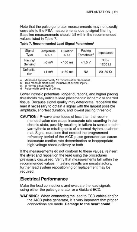
Note that the pulse generator measurements may not exactly correlate to the PSA measurements due to signal filtering. Baseline measurements should fall within the recommended values listed in Table 7.
Lower intrinsic potentials, longer durations, and higher pacing thresholds may indicate lead placement in ischemic or scarred tissue. Because signal quality may deteriorate, reposition the lead if necessary to obtain a signal with the largest possible amplitude, shortest duration, and lowest pacing threshold.
CAUTION: R-wave amplitudes of less than the recom-mended value can cause inaccurate rate counting in the chronic state, possibly resulting in failure to sense a tach-yarrhythmia or misdiagnosis of a normal rhythm as abnor-mal. Signal durations that exceed the programmed refractory period of the AICD pulse generator can cause inaccurate cardiac rate determination or inappropriate high-voltage shock delivery or both.
If the measurements do not conform to these values, reinsert the stylet and reposition the lead using the procedures previously discussed. Verify that measurements fall within the recommended values. If testing results are unsatisfactory, further lead system repositioning or replacement may be required.
Electrical PerformanceMake the lead connections and evaluate the lead signals using either the pulse generator or a Guidant ECD.
WARNING: When connecting the lead to ECD cables and/or the AICD pulse generator, it is very important that proper connections are made. Damage to the heart could
Table 7. Recommended Lead Signal Parametersa
a. Measured approximately 10 minutes after placement.
Signal Type
Amplitudea, b, c
b. This measurement is not inclusive of current injury.c. In normal sinus rhythm.
Durationa, b, c
Pacing Threshold d
d. Pulse width setting at 0.5 ms.
Impedance
Pacing/Sensing
>5 mV <100 ms <1.5 V300–
1200 Ω
Defibrilla-tion
>1 mV <150 ms NA 20–80 Ω
IMPLANTATION22
355458-001 RELIANCE/S active US355458_2.book Page 22 Monday, March 4, 2002 5:07 PM
result if a high-voltage defibrillating pulse were to be delivered through the pace/sense tip electrode.
Note: Prior to connecting the cardioversion/defibrillation leads to the ECD, ensure the ECD’s output circuitry is dis-abled and any electrocautery equipment is turned off and unplugged. Consult the ECD user’s manual for directions con-cerning connecting the ECD cables to the ECD and the ECD to a chart recorder.
Evaluating with the Pulse Generator
Connect the terminal pins to the pulse generator and place the AICD pulse generator into the AICD implant pocket as indicated in the AICD physician’s manual. Also, refer to “Connection to a Pulse Generator” (Page 28) for more information.
Evaluate the lead signals by viewing the real-time EGM. The signal from the implanted lead should be continuous and without artifact, similar to a body-surface ECG. A discontinuous signal may indicate a lead fracture or an otherwise damaged lead, or an insulation break that would necessitate lead replacement. Inadequate signals may result either in a failure of the AICD system to detect an arrhythmia or in an unnecessary delivery of therapy.
Evaluating with the ECD
Connect the pace/sense lead terminal pin to the sterile bipolar cable. Connect the defibrillation lead terminal pin(s) to the high-voltage cable. Then connect the bipolar and high-voltage cables to the respective connectors on the Guidant ECD.
Evaluate the lead signals using the Programmer/Recorder/Monitor (PRM) programming system or an external strip chart recorder. As seen on the strip chart recorder, the signal from the implanted lead should be continuous and without artifact, similar to a body-surface ECG. A discontinuous signal may indicate a lead fracture or otherwise damaged lead, or an insulation break that would necessitate lead replacement. Inadequate signals may result in failure of the AICD system to detect an arrhythmia or in unnecessary delivery of therapy.
CAUTIONS:
• Guidant ECDs are synchronized external cardioverter defibrillators capable of delivering high-energy pulses (up to 40 J) to the patient. If using an ECD, be thoroughly familiar with ECD operation prior to connecting the lead to the
IMPLANTATION 23
355458-001 RELIANCE/S active US355458_2.book Page 23 Monday, March 4, 2002 5:07 PM
ECD. Never use the ECD without a standard external defibrillator immediately available as a backup.
• Remove the stylet from the lead before connecting the lead to the ECD bipolar cable. A stylet left in the lead could (1) cause false electrical readings, (2) cause lead perforation, or (3) prevent use of a new stylet should relocation of the lead be necessary.
Conversion Testing After obtaining acceptable signals, use the AICD pulse generator or ECD to demonstrate ability to reliably convert ventricular fibrillation (VF) and, when appropriate to the patient, ventricular tachycardias. The ECD can substitute for an AICD pulse generator during conversion testing. This testing involves inducing arrhythmias and shocking the patient with high-voltage pulses delivered from the AICD pulse generator or ECD, through the defibrillation electrodes of the lead, to the heart.
CAUTION: Following an unsuccessful high-energy shock, miscounting of cardiac rate, delayed detection, or nonde-tection due to low amplitude VF signals, it may be neces-sary to reposition the lead or use a separate rate-counting electrode system. If a separate pace/sense electrode system (such as Guidant Model 4055 Sweet PicotipTM Rx) is used, its interelectrode spacing must be no greater than 1-2 cm because greater separation may cause the signal from the leads to exceed the refractory period of the AICD pulse generator, resulting in oversens-ing in normal rhythm, or undersensing in polymorphic rhythm.
In addition, a wide pace/sense electrode separation may contribute to oversensing by introducing a large repolar-ization signal (T-wave), thereby causing false fulfillment of the rate criteria.
Reliable conversion of VF should be demonstrated at an energy level less than the maximum energy setting of the pulse generator. Guidant recommends that multiple induction conversion tests of VF be performed to determine conversion reliability and the patient’s defibrillation threshold (DFT). It is a matter of clinical judgment as to what constitutes a demonstration of reliable conversion. Since the result of any single test is subject to statistical variation, a one-time conversion of a rhythm disturbance at a particular energy level
IMPLANTATION24
355458-001 RELIANCE/S active US355458_2.book Page 24 Monday, March 4, 2002 5:07 PM
does not necessarily predict future conversion energy levels. Refer to the applicable AICD physician’s manual for conversion testing guidelines.
Weigh the probability of reliable conversion in the ambulatory state against the availability of AICD energy settings and the patient’s ability to tolerate multiple arrhythmia inductions.
If a patient’s arrhythmia(s) cannot be reliably converted with an ENDOTAK RELIANCE or ENDOTAK RELIANCE S lead, supplementary implantation of an ENDOTAK SQ Array lead or an alternate lead system will require additional conversion testing. Refer to the ENDOTAK SQ Array lead physician’s manual for instructions concerning auxiliary use of this lead with the ENDOTAK RELIANCE and ENDOTAK RELIANCE S lead.
CAUTION: An ENDOTAK SQ Array lead may increase the energy required to cardiovert/defibrillate the heart with transthoracic paddles. Care should be taken not to place the external defibrillator paddles directly over the ENDOTAK SQ Array lead.
WARNING: Use of any component of the ENDOTAK lead system to assist in delivery of external-source rescue shocks could cause extensive tissue damage.
The decision to implant any AICD lead system in any configuration should be based on demonstration of adequate safety margins at the programmed shock energy as determined by DFT and cardioversion energy requirement (CER) testing. Refer to the applicable AICD physician’s manual for DFT and CER testing requirements.
Clinical study indicates that a programmed safety margin of 9–10 J above the patient’s DFT was used in the majority of patients. If a 9–10 J safety margin cannot be obtained by other, less invasive means, consider placing an additional defibrillation lead.
Note: If, after prolonged and repeated inductions of VF, a tho-racotomy is to be performed, consider performing it at a later date.
If using an ECD, turn off the ECD after arrhythmia testing has been completed and disconnect the ECD cables per instructions in the ECD user’s manual.
IMPLANTATION 25
355458-001 RELIANCE/S active US355458_2.book Page 25 Monday, March 4, 2002 5:07 PM
Securing the LeadAfter the electrodes are satisfactorily positioned and conversion testing has been performed, secure the lead to the vein to achieve permanent hemostasis and lead stabilization. Suture sleeve tie-down techniques can vary with the lead insertion technique used. Securing the lead will provide permanent hemostasis and lead stabilization.
Percutaneous Implant Technique
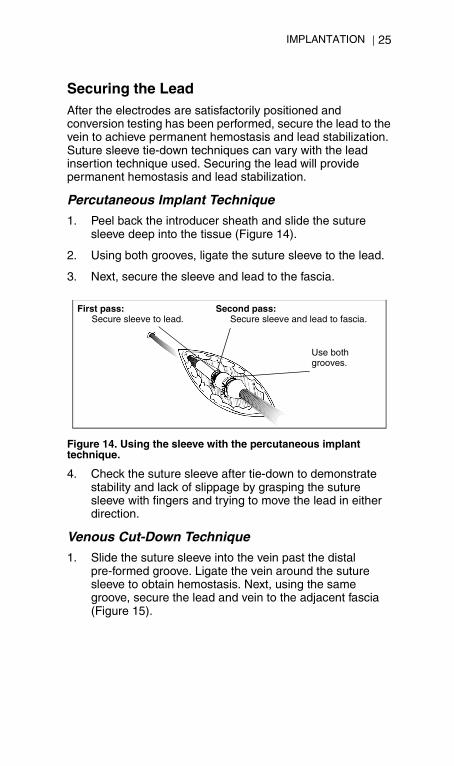
1. Peel back the introducer sheath and slide the suture sleeve deep into the tissue (Figure 14).
2. Using both grooves, ligate the suture sleeve to the lead.
3. Next, secure the sleeve and lead to the fascia.
4. Check the suture sleeve after tie-down to demonstrate stability and lack of slippage by grasping the suture sleeve with fingers and trying to move the lead in either direction.
Venous Cut-Down Technique
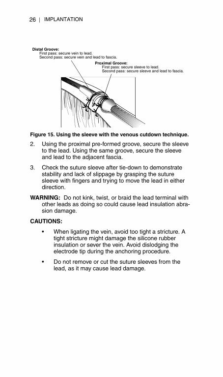
1. Slide the suture sleeve into the vein past the distal pre-formed groove. Ligate the vein around the suture sleeve to obtain hemostasis. Next, using the same groove, secure the lead and vein to the adjacent fascia (Figure 15).
Figure 14. Using the sleeve with the percutaneous implant technique.
First pass:Secure sleeve to lead.
Second pass:Secure sleeve and lead to fascia.
Use bothgrooves.
IMPLANTATION26
355458-001 RELIANCE/S active US355458_2.book Page 26 Monday, March 4, 2002 5:07 PM
2. Using the proximal pre-formed groove, secure the sleeve to the lead. Using the same groove, secure the sleeve and lead to the adjacent fascia.
3. Check the suture sleeve after tie-down to demonstrate stability and lack of slippage by grasping the suture sleeve with fingers and trying to move the lead in either direction.
WARNING: Do not kink, twist, or braid the lead terminal with other leads as doing so could cause lead insulation abra-sion damage.
CAUTIONS:
• When ligating the vein, avoid too tight a stricture. A tight stricture might damage the silicone rubber insulation or sever the vein. Avoid dislodging the electrode tip during the anchoring procedure.
• Do not remove or cut the suture sleeves from the lead, as it may cause lead damage.
Figure 15. Using the sleeve with the venous cutdown technique.
Distal Groove:First pass: secure vein to lead.Second pass: secure vein and lead to fascia.
Proximal Groove:First pass: secure sleeve to lead.Second pass: secure sleeve and lead to fascia.
IMPLANTATION 27
355458-001 RELIANCE/S active US355458_2.book Page 27 Monday, March 4, 2002 5:07 PM
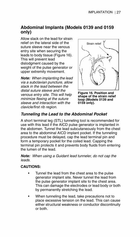
Abdominal Implants (Models 0139 and 0159 only)Allow slack on the lead for strain relief on the lateral side of the suture sleeve near the venous entry site when securing the leads to body tissue (Figure 16). This will prevent lead dislodgment caused by the weight of the pulse generator or upper extremity movement.
Note: When implanting the lead via a subclavian puncture, allow slack in the lead between the distal suture sleeve and the venous entry site. This will help minimize flexing at the suture sleeve and interaction with the clavicle/first rib region.
Tunneling the Lead to the Abdominal Pocket
A short terminal leg (STL) tunneling tool is recommended for use with this lead if the AICD pulse generator is implanted in the abdomen. Tunnel the lead subcutaneously from the chest area to the abdominal AICD implant pocket. If the tunneling procedure must be delayed, cap the lead terminal pin and form a temporary pocket for the coiled lead. Capping the terminal pin protects it and prevents body fluids from entering the lumen of the lead.
Note: When using a Guidant lead tunneler, do not cap the leads.
CAUTIONS:
• Tunnel the lead from the chest area to the pulse generator implant site. Never tunnel the lead from the pulse generator implant site to the chest area. This can damage the electrodes or lead body or both by permanently stretching the lead.
• When tunneling the lead, take precautions not to place excessive tension on the lead. This can cause either structural weakness or conductor discontinuity or both.
Strain relief
Figure 16. Position and shape of the strain relief loop (Models 0139 and 0159 only).
IMPLANTATION28
355458-001 RELIANCE/S active US355458_2.book Page 28 Monday, March 4, 2002 5:07 PM
• After tunneling, re-evaluate the lead to verify that no significant change in signals or damage to the lead has occurred during the tunneling procedure.
Reattach the lead terminals to the AICD pulse generator or ECD cables. If the measurements are unacceptable, check the electrical connections. A discontinuous or abnormal signal may indicate dislodgment, a loose connection, or lead damage. If necessary, reposition the lead electrodes until acceptable values are obtained. To reposition the lead, carefully withdraw the tunneled portion back to the venous entry site. Release the permanent ligatures and reposition the lead using procedures previously discussed.
Connection to a Pulse GeneratorConsult the AICD physician’s manual for directions concerning connecting the lead terminals to the pulse generator.
Verify the stylet is removed prior to connecting the lead to the pulse generator.
CAUTION: Insert the IS-1 lead terminal straight into the lead port. Do not bend the lead near the lead-header interface. Improper insertion can cause insulation damage near the terminal ring that could result in lead damage.
Notes: • If necessary, lubricate the lead terminal sparingly with ster-
ile water to make insertion easier.• If the lead terminal pin will not be connected to an AICD
pulse generator at the time of lead implantation, the lead connector must be capped before closing the pocket inci-sion. Place a suture around the lead cap to keep it in place.
• Plug any unused DF-1 lead port on the pulse generator with the DF-1 port plug (ENDOTAK RELIANCE S lead only).
The pace/sense terminal is inserted into the AICD lead port identified as the pacing/sensing port. The defibrillation terminals are inserted into the AICD lead ports identified as defibrillation, maintaining the polarity and electrode configuration determined during DFT testing.
POST-IMPLANT EVALUATION 29
355458-001 RELIANCE/S active US355458_2.book Page 29 Monday, March 4, 2002 5:07 PM
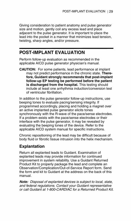
Giving consideration to patient anatomy and pulse generator size and motion, gently coil any excess lead and place adjacent to the pulse generator. It is important to place the lead into the pocket in a manner that minimizes lead tension, twisting, sharp angles, and/or pressure.
POST-IMPLANT EVALUATIONPerform follow-up evaluation as recommended in the applicable AICD pulse generator physician’s manual.
CAUTION: For some patients, lead performance at implant may not predict performance in the chronic state. There-fore, Guidant strongly recommends that post-implant follow-up EP testing be performed before the patient is discharged from the hospital. This testing should include at least one arrhythmia induction/conversion test of ventricular fibrillation.
In addition to the pulse generator follow-up instructions, use beeping tones to evaluate pacing/sensing integrity. If programmed accordingly, placing and holding a magnet over an active implanted pulse generator elicits tones synchronously with the R-wave of the pace/sense electrodes. If a problem exists with the pace/sense electrodes or their interface with the pulse generator, it may be revealed by evaluating the beeping tones of the device. Refer to the applicable AICD system manual for specific instructions.
Chronic repositioning of the lead may be difficult because of body fluid or fibrotic tissue intrusion into the helix mechanism.
ExplantationReturn all explanted leads to Guidant. Examination of explanted leads may provide information for continued improvement in system reliability. Use a Guidant Returned Product Kit to properly package the lead and complete an Observation/Complication/Out-of-Service Report form. Send the form and kit to Guidant at the address on the back of this manual.
Note: Disposal of explanted devices is subject to local, state, and federal regulations. Contact your Guidant representative or call Guidant at 1-800-CARDIAC for a Returned Product Kit.

REFERENCES30
355458-001 RELIANCE/S active US355458_2.book Page 30 Monday, March 4, 2002 5:07 PM
REFERENCES1. DF-1 refers to the international standard ISO
11318:1993.
2. IS-1 refers to the international standard ISO 5841.3:1992.
3. Magney JE, et al. Anatomical mechanisms explaining damage to pacemaker leads, defibrillator leads, and fail-ure of central venous catheters adjacent to the sterno-clavicular joint. PACE. 1993;16:445-457.
4. Magney JE, et al. A new approach to percutaneous sub-clavian venipuncture to avoid lead fracture or central venous catheter occlusion. PACE. 1993;16:2133-2141.
5. Epstein AE, et al. Combined automatic implantable car-dioverter-defibrillator and pacemaker systems: implanta-tion techniques and follow-up. JACC. 1989;13:121-131.
6. Calkins H, et al. Clinical interactions between pacemak-ers and automatic implantable cardioverter-defibrillators. JACC. 1990;16:666-673.
SPECIFICATIONS (Nominal) 31
355458-001 RELIANCE/S active US355458_2.book Page 31 Monday, March 4, 2002 5:07 PM
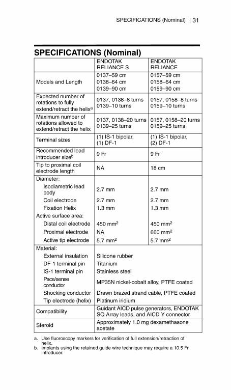
SPECIFICATIONS (Nominal)ENDOTAK RELIANCE S
ENDOTAKRELIANCE
Models and Length0137–59 cm0138–64 cm0139–90 cm
0157–59 cm0158–64 cm0159–90 cm
Expected number of rotations to fully extend/retract the helixa
a. Use fluoroscopy markers for verification of full extension/retraction of helix.
0137, 0138–8 turns0139–10 turns
0157, 0158–8 turns0159–10 turns
Maximum number of rotations allowed to extend/retract the helix
0137, 0138–20 turns0139–25 turns
0157, 0158–20 turns0159–25 turns
Terminal sizes (1) IS-1 bipolar, (1) DF-1
(1) IS-1 bipolar, (2) DF-1
Recommended lead introducer sizeb
b. Implants using the retained guide wire technique may require a 10.5 Fr introducer.
9 Fr 9 Fr
Tip to proximal coil electrode length NA 18 cm
Diameter:Isodiametric lead body 2.7 mm 2.7 mm
Coil electrode 2.7 mm 2.7 mmFixation Helix 1.3 mm 1.3 mm
Active surface area:
Distal coil electrode 450 mm2 450 mm2
Proximal electrode NA 660 mm2
Active tip electrode 5.7 mm2 5.7 mm2
Material:External insulation Silicone rubberDF-1 terminal pin TitaniumIS-1 terminal pin Stainless steelPace/sense conductor MP35N nickel-cobalt alloy, PTFE coated
Shocking conductor Drawn brazed strand cable, PTFE coatedTip electrode (helix) Platinum iridium
Compatibility Guidant AICD pulse generators, ENDOTAK SQ Array leads, and AICD Y connector
Steroid Approximately 1.0 mg dexamethasone acetate

355458_2.book Page 38 Monday, March 4, 2002 5:07 PM

355458_2.book Page 39 Monday, March 4, 2002 5:07 PM

355458_2.book Page 39 Monday, March 4, 2002 5:07 PM

355458_2.book Page 39 Monday, March 4, 2002 5:07 PM

Guidant Corporation
Cardiac Rhythm Management4100 Hamline Avenue NorthSt. Paul, MN 55112-5798 USA
24-Hour Consultation1-800-CARDIAC (227-3422)Worldwide: 651-582-4000www.guidant.com
© 2002 Guidant Corporation
All rights reserved. 355458-002 A 3/02
355458_2.book Page 34 Monday, March 4, 2002 5:07 PM