Embed Size (px)
Citation preview
Physics 2102Physics 2102Lecture 19Lecture 19
Ch 30:Ch 30:Inductors and RL CircuitsInductors and RL Circuits
Physics 2102
Jonathan Dowling
Nikolai Tesla
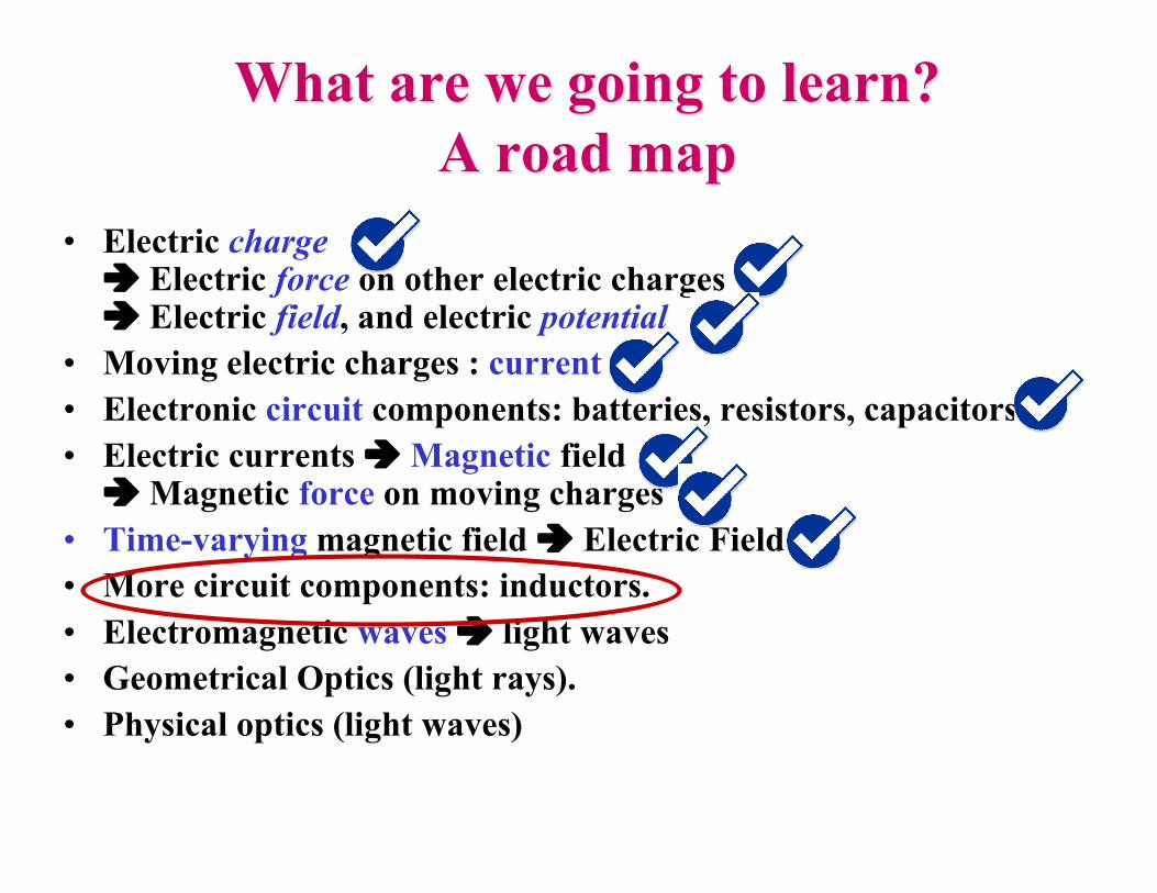
What are we going to learn?What are we going to learn?A road mapA road map
• Electric charge Electric force on other electric charges Electric field, and electric potential
• Moving electric charges : current• Electronic circuit components: batteries, resistors, capacitors• Electric currents Magnetic field
Magnetic force on moving charges• Time-varying magnetic field Electric Field• More circuit components: inductors.• Electromagnetic waves light waves• Geometrical Optics (light rays).• Physical optics (light waves)
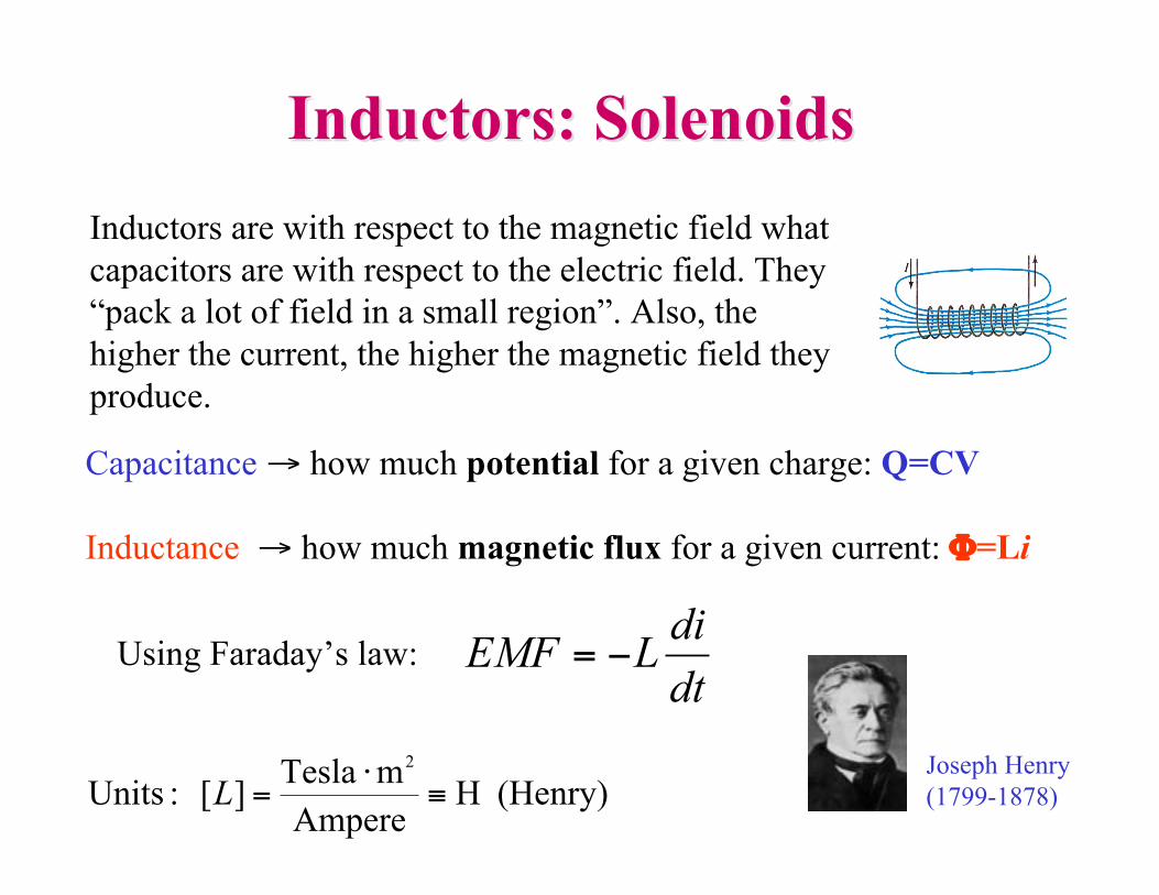
Inductors are with respect to the magnetic field whatcapacitors are with respect to the electric field. They“pack a lot of field in a small region”. Also, thehigher the current, the higher the magnetic field theyproduce.
Capacitance → how much potential for a given charge: Q=CV
Inductance → how much magnetic flux for a given current: Φ=Li
(Henry)H Ampere
mTesla][ :Units
2
!"
=LJoseph Henry (1799-1878)
Inductors: SolenoidsInductors: Solenoids
dt
diLEMF !=Using Faraday’s law:
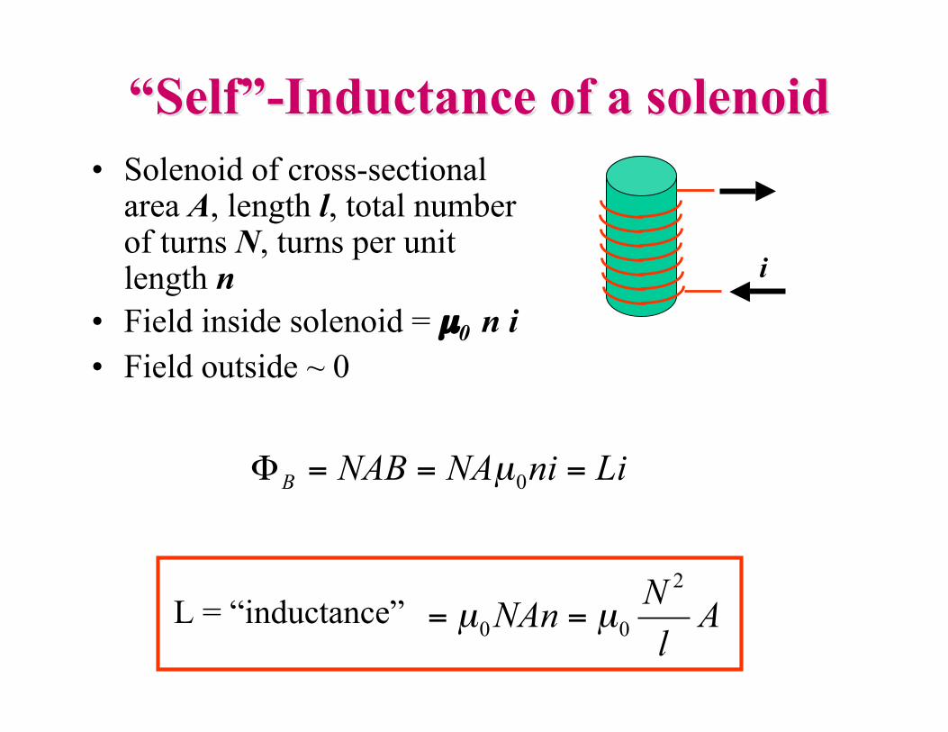
““SelfSelf””-Inductance of a solenoid-Inductance of a solenoid• Solenoid of cross-sectional
area A, length l, total numberof turns N, turns per unitlength n
• Field inside solenoid = µ0 n i• Field outside ~ 0
i
Al
NNAn
2
00µµ ==L = “inductance”
LiniNANABB
===!0
µ
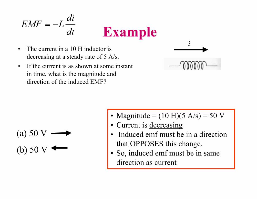
ExampleExample• The current in a 10 H inductor is
decreasing at a steady rate of 5 A/s.• If the current is as shown at some instant
in time, what is the magnitude anddirection of the induced EMF?
• Magnitude = (10 H)(5 A/s) = 50 V• Current is decreasing• Induced emf must be in a direction
that OPPOSES this change.• So, induced emf must be in same
direction as current
(a) 50 V
(b) 50 V
idt
diLEMF !=
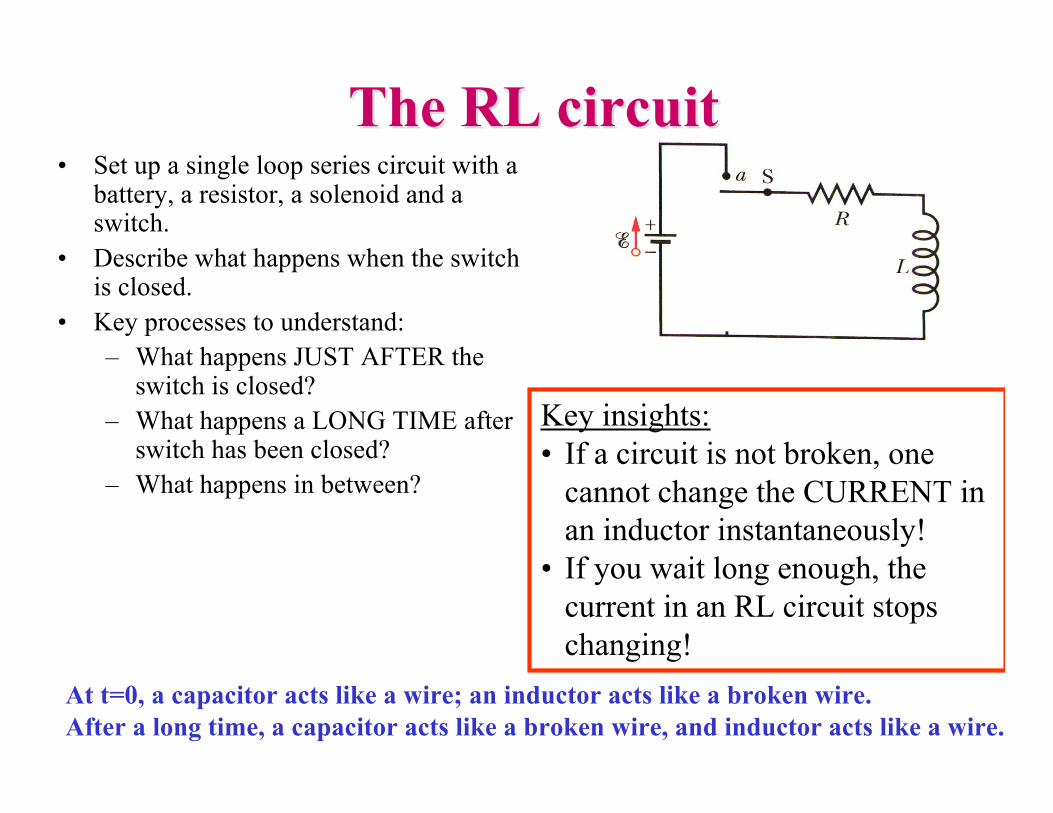
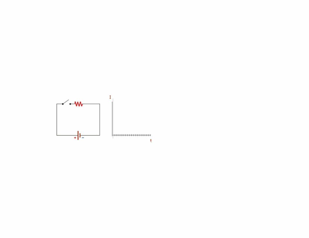
The RL circuitThe RL circuit• Set up a single loop series circuit with a
battery, a resistor, a solenoid and aswitch.
• Describe what happens when the switchis closed.
• Key processes to understand:– What happens JUST AFTER the
switch is closed?– What happens a LONG TIME after
switch has been closed?– What happens in between?
Key insights:• If a circuit is not broken, one
cannot change the CURRENT inan inductor instantaneously!
• If you wait long enough, thecurrent in an RL circuit stopschanging!
At t=0, a capacitor acts like a wire; an inductor acts like a broken wire. After a long time, a capacitor acts like a broken wire, and inductor acts like a wire.
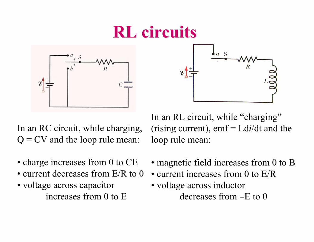
RL circuitsRL circuits
In an RC circuit, while charging,Q = CV and the loop rule mean:
• charge increases from 0 to CE• current decreases from E/R to 0• voltage across capacitor increases from 0 to E
In an RL circuit, while “charging”(rising current), emf = Ldi/dt and theloop rule mean:
• magnetic field increases from 0 to B• current increases from 0 to E/R• voltage across inductor decreases from −E to 0
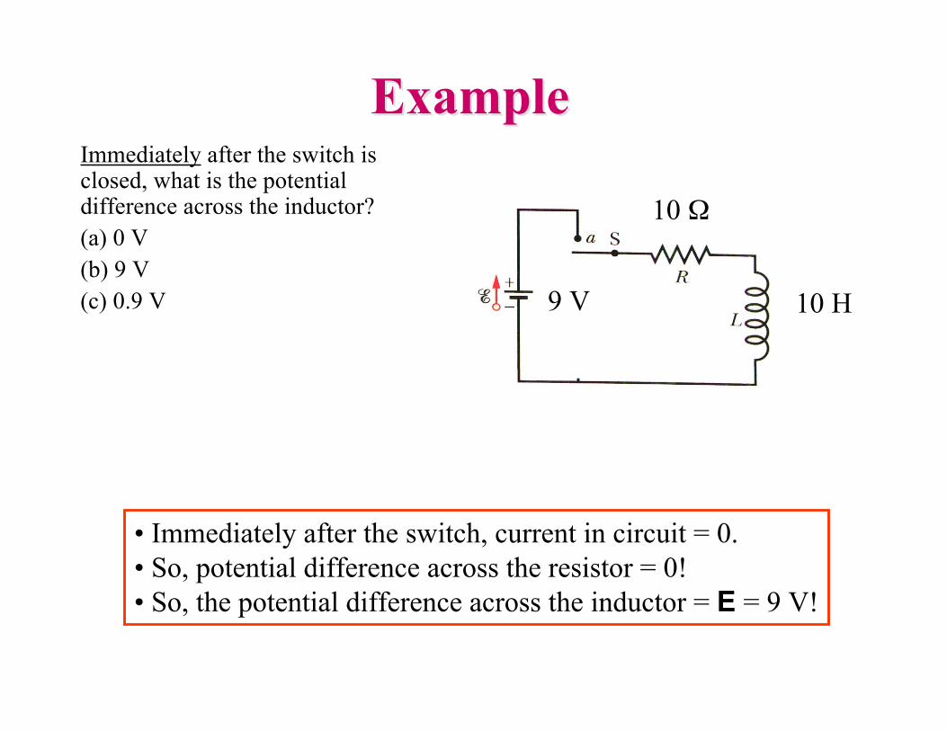
ExampleExampleImmediately after the switch isclosed, what is the potentialdifference across the inductor?(a) 0 V(b) 9 V(c) 0.9 V
• Immediately after the switch, current in circuit = 0.• So, potential difference across the resistor = 0!• So, the potential difference across the inductor = E = 9 V!
10 Ω
10 H9 V
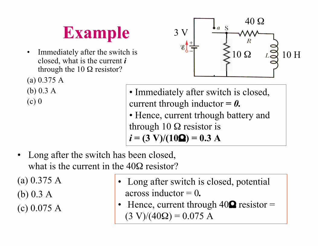
ExampleExample• Immediately after the switch is
closed, what is the current ithrough the 10 Ω resistor?
(a) 0.375 A(b) 0.3 A(c) 0
• Long after the switch has been closed,what is the current in the 40Ω resistor?
(a) 0.375 A(b) 0.3 A(c) 0.075 A
• Immediately after switch is closed,current through inductor = 0.• Hence, current trhough battery andthrough 10 Ω resistor isi = (3 V)/(10Ω) = 0.3 A
• Long after switch is closed, potentialacross inductor = 0.
• Hence, current through 40Ω resistor =(3 V)/(40Ω) = 0.075 A
40 Ω
10 H
3 V
10 Ω
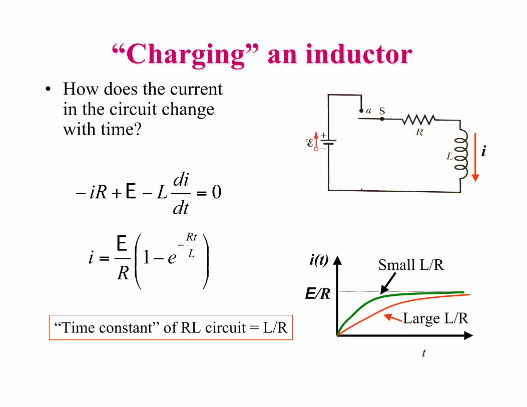
““ChargingCharging”” an inductor an inductor• How does the current
in the circuit changewith time?
0=!+!dt
diLiR E
!!"
#$$%
&'=
'L
Rt
eR
i 1E
“Time constant” of RL circuit = L/Rt
E/R
i(t) Small L/R
Large L/R
i
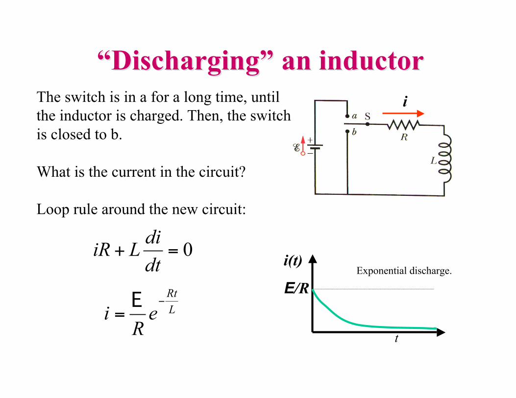
““DischargingDischarging”” an inductor an inductor
0=+dt
diLiR
L
Rt
eR
i!
=E
t
E/RExponential discharge.
i(t)
iThe switch is in a for a long time, untilthe inductor is charged. Then, the switchis closed to b.
What is the current in the circuit?
Loop rule around the new circuit:
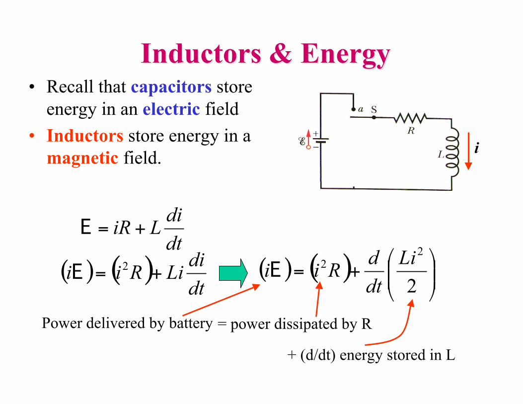
Inductors & EnergyInductors & Energy• Recall that capacitors store
energy in an electric field• Inductors store energy in a
magnetic field.
dt
diLiR +=E
( ) ( )dt
diLiRii += 2
E ( ) ( ) !!"
#$$%
&+=
2
2
2 Li
dt
dRiiE
Power delivered by battery = power dissipated by R
i
+ (d/dt) energy stored in L
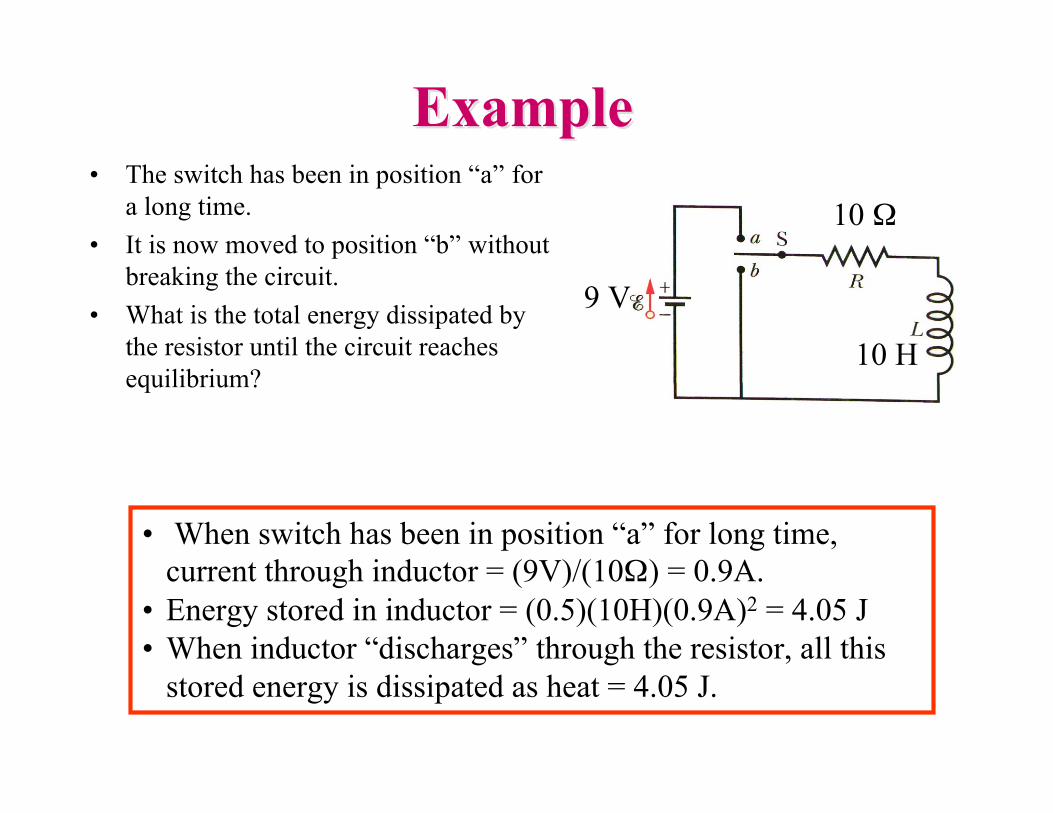
ExampleExample• The switch has been in position “a” for
a long time.• It is now moved to position “b” without
breaking the circuit.• What is the total energy dissipated by
the resistor until the circuit reachesequilibrium?
• When switch has been in position “a” for long time,current through inductor = (9V)/(10Ω) = 0.9A.
• Energy stored in inductor = (0.5)(10H)(0.9A)2 = 4.05 J• When inductor “discharges” through the resistor, all this
stored energy is dissipated as heat = 4.05 J.
9 V
10 Ω
10 H
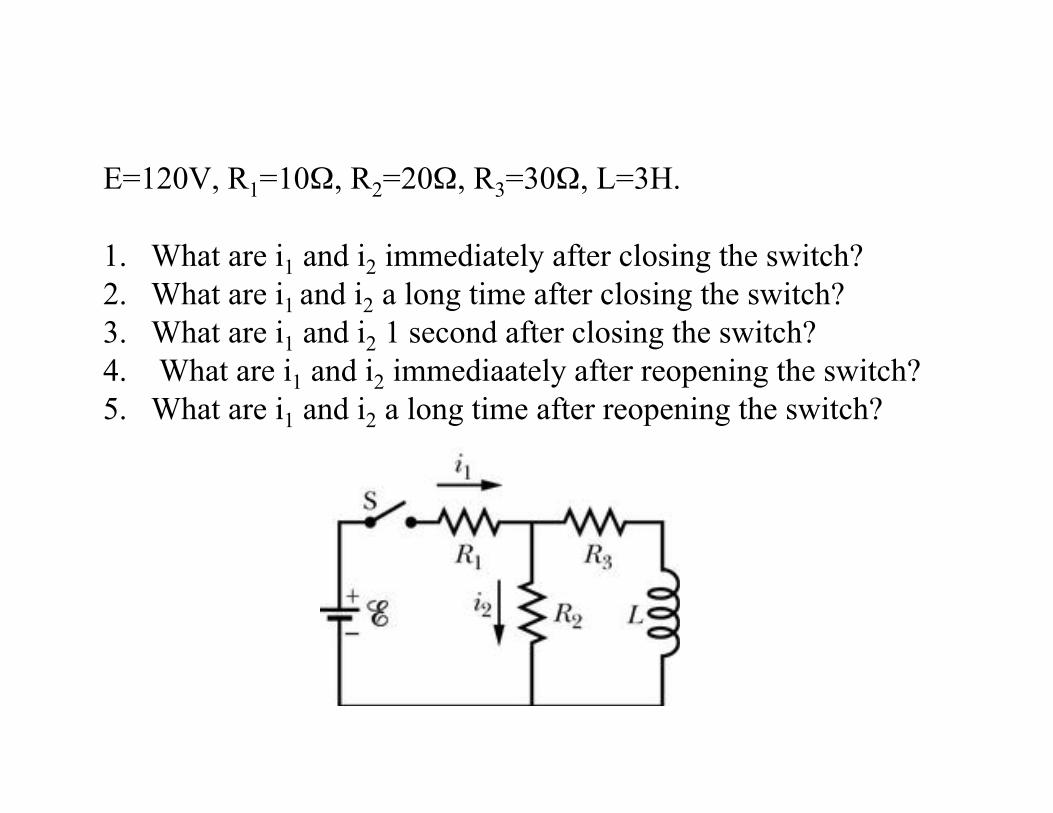
E=120V, R1=10Ω, R2=20Ω, R3=30Ω, L=3H.
1. What are i1 and i2 immediately after closing the switch?2. What are i1 and i2 a long time after closing the switch? 3. What are i1 and i2 1 second after closing the switch? 4. What are i1 and i2 immediaately after reopening the switch? 5. What are i1 and i2 a long time after reopening the switch?