Embed Size (px)
Citation preview

Physics and Treatment planning of Image Guided Radiotherapy
Dr. V. SUBRAMANI, Ph.D,Chief Medical Physicist
Department of Radiation Oncology, All India Institute of Medical Sciences, New Delhi

Learning objectives
� Basics of IGRT: Definition, goal, rationale, limitation
� Historical perspective of IGRT
� Modern IGRT technologies
� IGRT management for geometric uncertainties
� Correction strategies for patient positioning in IGRT
� Image registration in IGRT
� Imaging dose considerations in IGRT
� Summary and conclusion

Image Guided Radiotherapy

Basics of IGRT
What is image guided radiotherapy?It is a process of frequent imaging in the treatment room during a course of radiotherapy that allows treatment decisions made on the basis of imaging
Goal To manage the inter and intra fraction variation in shapes, volumes of target and patient positions and, organ motion to improve the geometric accuracy in dose delivery

Rationale of Image Guidance
� To account for geometric variation of
• Target(s)
• Organs-at-risk
• Patient
� To address dosimetric variability
• Inter-fraction
• Intra-fraction
� To ensure that anticipated benefits from 3DCRT & IMRT are realized
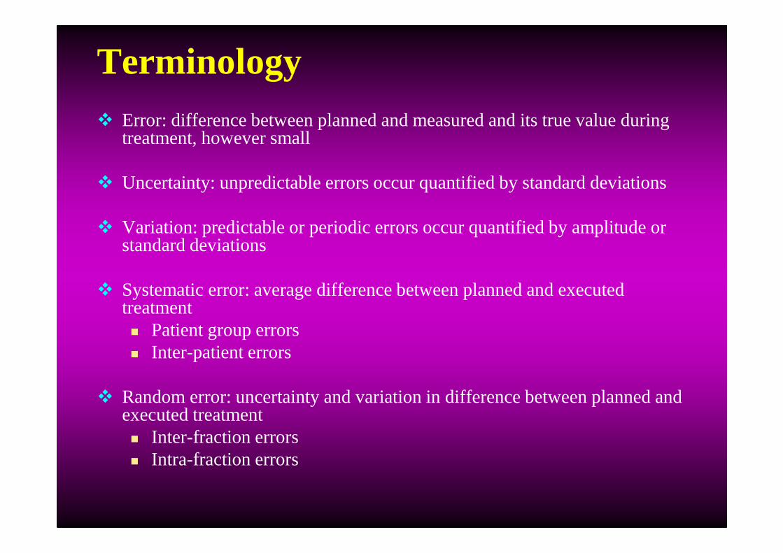
Terminology� Error: difference between planned and measured and its true value during
treatment, however small
� Uncertainty: unpredictable errors occur quantified by standard deviations
� Variation: predictable or periodic errors occur quantified by amplitude or standard deviations
� Systematic error: average difference between planned and executed treatment� Patient group errors� Inter-patient errors
� Random error: uncertainty and variation in difference between planned and executed treatment� Inter-fraction errors� Intra-fraction errors

Need for image guidance in RT?� Interfraction and Intrafraction setup error and organ motion
are key parameters in determining the geometric accuracy
� In moving targets, large target motions due to the inherent movement within the patient such as physiologic or respiratory motion
� The magnitude of target motion is variable and unpredictable
� Necessitates higher degree of accuracy and precision in target localization and repositioning in-room verification during the course of treatment
� Geometric error translates to dosimetric errors, resulting in deviation in planned dose vs. delivered dose
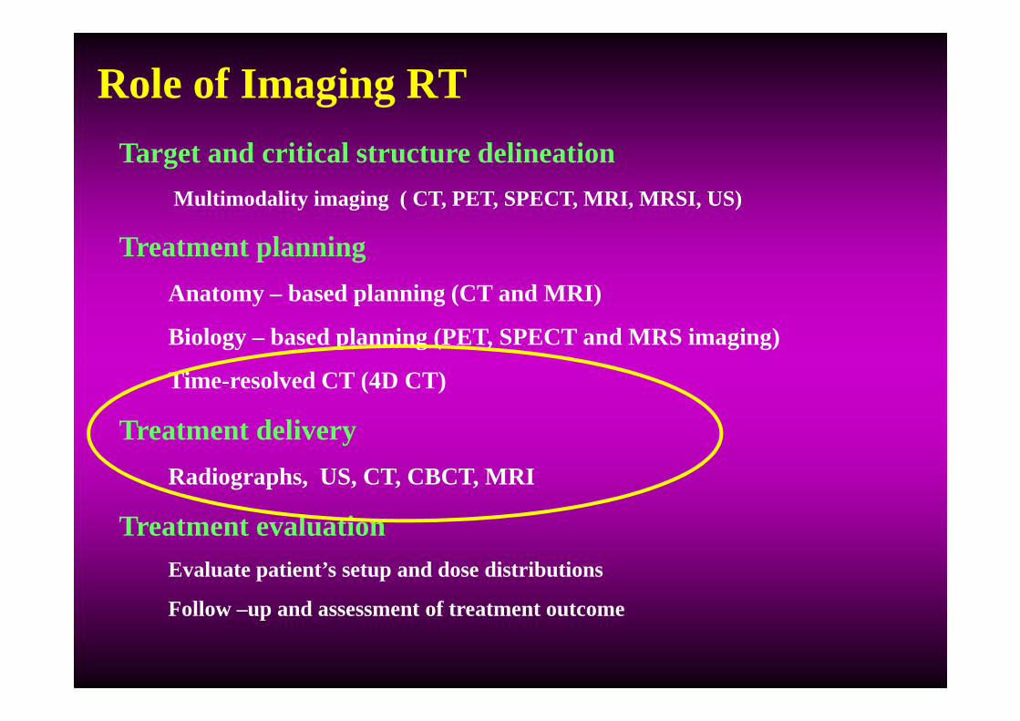
Role of Imaging RT
Target and critical structure delineation
Multimodality imaging ( CT, PET, SPECT, MRI, MRSI, US)
Treatment planning
Anatomy – based planning (CT and MRI)
Biology – based planning (PET, SPECT and MRS imaging)
Time-resolved CT (4D CT)
Treatment delivery
Radiographs, US, CT, CBCT, MRI
Treatment evaluation Evaluate patient’s setup and dose distributions
Follow –up and assessment of treatment outcome

Potential and limitation of IGRTAdvantage � Improves the accuracy in the radiation field placement
� Determine the optimal margin to reduce the dose to the surrounding normal tissue
� Allows tumor dose escalation, thereby increasing local tumor control and survival
Disadvantage� Imaging dose to Patient
� Redefining workload
� Resources/Infrastructure

Clinical Indication for IGRT� Tumors adjacent to critical structures
� Tumors prone to inter fractional motion
� Tumors prone to intra fractional motion
� Tumors prone to deformation
� IMRT, SRS/SRT/SBRT
� Hypofractionation scheme
Clinical sites: Thorax, Abdomen and Pelvis

Hypo fractionation
De-formation
Organ motion
Set-up error
Intra fraction
Inter fraction
Intra fraction
Inter fraction
Stereotactic approach
TrackingGatingBreath hold
4DCT
slow CT
shallow forced
forced
voluntary
external
internalRobotic
linac
MLC
frame
frameless
dosevolume
IGRT
Motion encompassing
Robotic couch

IGRT
Dimensionality
Radiation (energy)
Location of image guidance system
Geometric uncertainties management
Inter-fraction Intrafraction
Peripheral On-board Integrated systems
KV MV
IGRT classification
Non-radiographic
Planar systems (2D) Volumetric systems (3D)

Historical perspective of IGRT

Evolution of Imaging for treatment verification
� 1980’s - port films
� 1990’s - emergence of MV portal imagers, in-room ultrasound localization, marker-based localization & Fluoroscopic tracking
� 2000’s - Flat panel imaging, KV digital imaging, CBCT, MV CBCT and CT “on rails”
� Emerging - Electromagnetic localization and trackingin-room MRI

Historical IGRT technologies
1958- Holloway et.al reported portable x-ray machine mounted on the counter weight to TheratronCo-60 machine

“The XOTRON”
1959-John & Cunnigham described 60CO unit multivane collimator / ion chamber for invivo dosimetry. 100Kv x- ray source mounted in the CO-60 unit – “Xotron”

The Stanford Medical Linear Accelerator IGRT
1958-Weissbluth et. al introduced the concept of in-room imaging with integrated diagnostic x-ray unit in the linac head. -Stanford Linear accelerator
fluoroscope Linac
Isocentric chair

Cobalt-IGRT
1960- Lokkerbol et al designed Cobalt based IGRT system: The base part of the construction is a sturdy ring (460mm) partly sunk in the floor enabling rotation of 540 degrees
Co-60 head unit
120kV diagnostic X-ray unitImage intensifier
coupled with vedicon camera
Counter weight
Ion chamber for exit dosimetry

Linac with IGRT
1985- Biggs et.al re-initiated the diagnostic (X-ray unit) quality portals for MV accelerators head
Diagnostic beam pass through the isocenter of the treatment beam center

Current IGRT Technologies

Current IGRT technologies
Ultrasound Video-Based Planar: X-Ray Volumetric
BAT
SonArray
I-Beam
Restitu
Video Subtraction
Photogrammetry
AlignRT
Real-Time Video
EPID
CyberKnife
Novalis
RTRT
Gantry-Mounted Prototype
Tohoku.
IRIS Commercial
Varian OBI
Elekta Synergy
In-Room CT
FOCAL, MSKCC
CT-on-Rails
Primation
Varian ExaCT
Tomotherapy
MV Cone Beam CT
Siemens
kV Cone Beam CT
Mobile C-arm
Varain OBI
Elekta Synergy
Siemens In-Line

2D MV imaging: EPID
� Camera-based, Matrix liquid ionization chambers & a:Si Active matrix flat panel
� To align the patient position relative to the radiation beams/isocenter
� To verify the shape of the treatment portals
Advantage:
� Direct in-field verification of treatment
Disadvantages:
� MV imaging imaging dose (1 to 5 cGy)
� Poor image quality
Planar image guidance systems

EPID
� Initiated the IGRT ‘culture’ both off-line and on-line
� Image created with treatment beam
� Direct verification of alignment target-beam
� Verification of field, MLC, dose, …
� Only 2D information (requires multiple gantry positions for 3D info)
� Requires surrogate to localize target
� Not straightforward to use during beam-on (e.g. IMRT, gating)
� Longevity of camera’s & flat panels ?
ConsPros

� kV x-ray tube, flat-panel imager
� diagnostic quality x-ray images
Advantage � kV contrast is superior to MV
imaging
� Imaging dose is low
Disadvantage� 3D volumes of soft tissue targets is
not possible
2D KV x-ray imaging: On-board imagers

� Orthogonal pair of x-ray images are used
� landmark point in 3-D space.
Advantage� superior image quality to visualize bony
structures
� low imaging dose
Disadvantage� 3D target localization
� volume changes of target and OAR is not possible
In-room kV 2D Stereoscopic kV imaging
BrainLAB-Novalis
Cyberknife
X-ray tubes
aSi detector

In-room kV-X-ray imaging : Hakkaido system
� combination of multiple x-ray source/ detector
� useful for internal gating
Advantage:
� high mechanical stability
� real time 3D information is available
Disadvantages:
� imaging isocenter is not treatment isocenter
� Requires surrogates
Real-time tumor tracking system
Shirato et al IJROBP 48:435-442, 2000

kV CT: In-room conventional CT or CT-on-Rails
Siemens Primatom
Varian ExaCT
� 1996 -first integrated system of linac and CT in Tx room, Japan
Advantages
� simplest form of IGRT
� familiarity of the diagnostic quality CT images.
Disadvantages
� A couch correction is used to realign the patient
� In-room CT solution extends the treatment planning activities
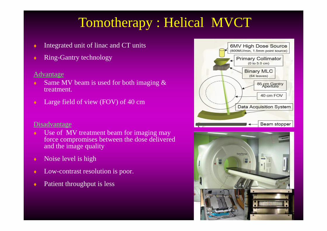
� Integrated unit of linac and CT units
� Ring-Gantry technology
Advantage� Same MV beam is used for both imaging &
treatment.
� Large field of view (FOV) of 40 cm
Disadvantage� Use of MV treatment beam for imaging may
force compromises between the dose delivered and the image quality
� Noise level is high
� Low-contrast resolution is poor.
� Patient throughput is less
Tomotherapy : Helical MVCT
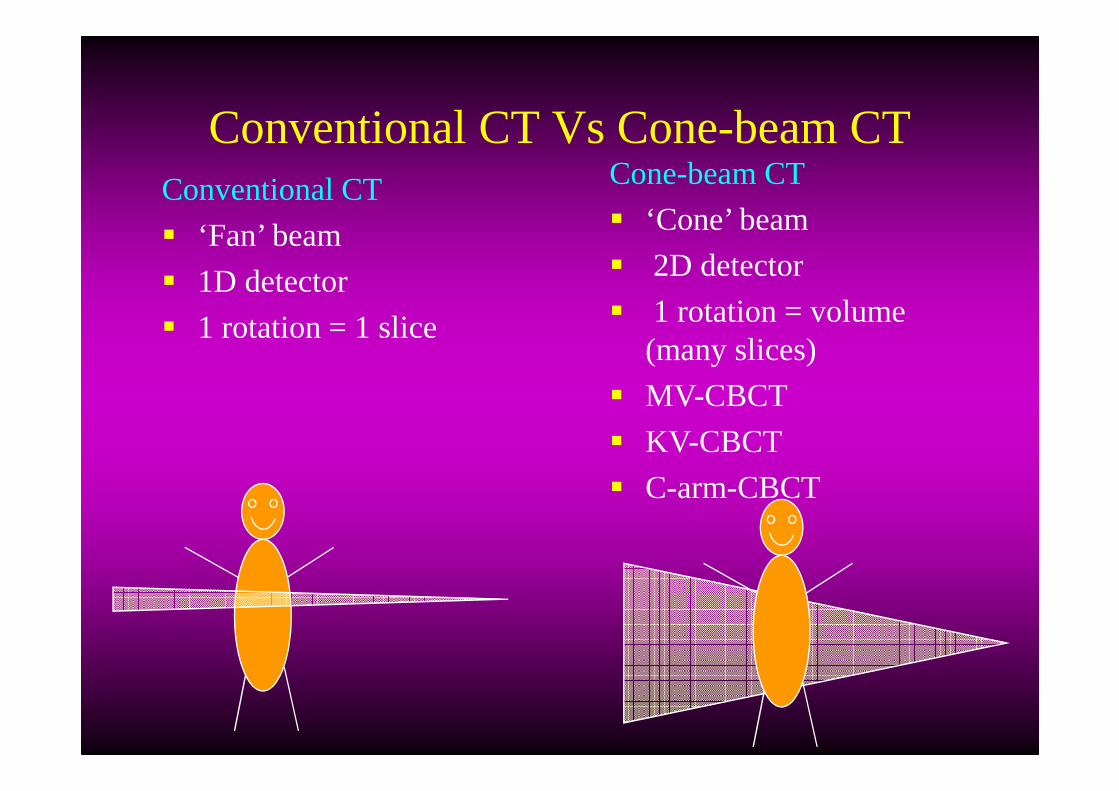
Conventional CT Vs Cone-beam CTConventional CT
� ‘Fan’ beam
� 1D detector
� 1 rotation = 1 slice
Cone-beam CT
� ‘Cone’ beam
� 2D detector
� 1 rotation = volume (many slices)
� MV-CBCT
� KV-CBCT
� C-arm-CBCT

� Flat-panel detectors based EPID mounted on a linac gantry and the therapy MV x-ray
� Possible to acquire multiple, low-dose 2-D projection images
Advantages:
� Suitable for bony tumor
� uses a large detector and a single rotation
Disadvantage:
� lack of discrimination of soft tissue and bony objects by the physics of high-energy x-rays.
Megavoltage cone-beam CT (MV-CBCT)

� Radiography, fluoroscopy, and CBCT
� large flat-panel imager
� kV x-ray tube mounted on a retractable arm at 90 degrees to the treatment beam line.
� Cone-beam CT reconstruction acquiring multiple kV radiographs as the gantry rotates through at least 180 degrees
Advantages� real-time information is available� no surrogates required
Disadvantages� mechanically less stable� requires careful calibration
kV-CB CT : On-board imager

Volumetric imaging: Siemens kV CBCT
MV-source
Flat panel: kV
Flat panel: MV
kV-source

Advantages
� no surrogate required (soft tissue visualization)
� remaining random error same magnitude as with initial set-up
Disadvantages
� CT-contour ≠US-structure
� Important inter-user variability
Non-Radiographic techniques: Ultrasound
Non invasive
No radiographic
Relatively easy imaging

� to induce and detect signals from implanted wireless devices
� optical tracking system and a tracking station console
� source coils & sensor coils
� position of transponder without using the radiographic method
Advantage:� update target position ten times / second &
very fast
� sub millimeter tracking accuracy
Electromagnetic Field Tracking: Calypso system

� Hybrid MRI-linac & MRI-cobalt-60 machines
� 3 Co-60 source & 0.3 T open field magnet
� MLC system provides gamma-ray intensity modulation
MRI- track a patient's 3-D anatomy every 0.5-2.0s
- superior soft tissue contrast &
- near real-time, volumetric soft tissue targeting system.
MRI based Real-time Volumetric Tracking

Adaptive Radiotherapy
ART� Systematic improvement of a
treatment plan in response to temporal patient/organ variations observed during therapy
Temporal variations� Patient/organ geometrical shape
and position
� Biological parameters of tissues
� Time Adaptation of treatment parameters
� Feed Back‘ based on information provided by images
� Evaluation: requires treatment quality indicators
e.g. accumulated dose
Key component of ART

Adaptivity levelsLevel I
Level II
Level III
Observation prior to treatment
Random + systematic setup errors
Organ motion (random, periodic)
Observation prior to each fraction
Random + systematic setup errors
Organ motion (random, periodic)
Observation prior to and during each fraction
Intrafractional setup errors, organ motion
Real time patient and organ movement
Prediction of margins
Adaptation of treatment parameters in each fraction
Dynamic adaptation of treatment parameters

IGRT and ART
Image Patient
Planpatient
Treat patient
Image patient
PlanPatient
Imagepatient
Treat patient
Image patient
Planpatient
Treatpatient
Imagepatient
Planpatient
Image Patient
Planpatient
Treat patient
Image guided RT
Days Days
Days Days
Days
Days Days
Offline adaptive RT
Online image guided adaptive RT
Days

Stereotactic Body Radiotherapy (SBRT)
� Treatment method using external beams to treat lesions of the body targets with ultra-high dose of radiation in a single dose (Radiosurgery) or (few) small number of fractions (Radiotherapy)
� With high precision tumor identification and relocalization employing “stereotactic” and image guidance approaches
� Extracranial Stereotactic Radiosurgery / Radiotherapy
� Radioablation / Body Radiosurgery / Radiotherapy called
“Stereotactic Body Radiotherapy (SBRT)”

IGRT management for Geometric uncertainties

IGRT for management of geometric uncertainties
Interfraction error is due to
� Immobilization devices used
� Organ filling levels (day-to day situation
� Organ distenstion due to bowel and rectum gas pressure
� Supine vs prone position
Goal : Reduction of Set-up margin

Geometric uncertainties in Target definitionAccurate definition of target volume� volumes not contoured may not get treated lead to geographical miss
� volumes varies with imaging modality
� subject to inter-observer variability
� remains as largest error of geometric uncertainties in radiotherapy
�systematic error originates from treatment preparation stage
Steenbakkers et al, IJROBP 2005

Geometric uncertainties in patient set-up
Systematic errors (Σ)� treatment preparation errors
� influence all fractions
� deleterious effect
� larger
Random errors (σ)� treatment execution errors
� influence each fraction individually
� detrimental effect
� smaller
Σ small, σ small Σ small, σ large
Σ large, σ small Σ large, σ large

ICRU-62 Guidelines on MarginsSetup margin (SM)� Variation in patient-beam positioning in reference
to the treatment machine coordinate system� Related to technical factors
� Can be reduced by:� Accurate setup and immobilization of the
patient � Improved mechanical stability of the machine
Internal margin (IM)� Variations in size, shape, and position of the CTV in
reference to the patient’s coordinate system using anatomic reference points.
� Caused by physiologic variations
� Difficult to control from a practical viewpoint.
� The volume formed by the CTV and the IM called Internal target volume (ITV )

Computing PTV margins
Error (SD) Lung classic
Imaging snapshot setup Σ 4 mm
Imaging snapshot organ Σ 3 mm
Imaging snapshot respiration Σ
A=10 mm → 3.3 mm
Delineation Σ 4 mm
Treatment setup σ 4 mm
Treatment organ motion σ 3 mm
Treatment respiration σ A=10 mm → 3.3 mm
Margin M 22 mm
M ≈ 2.5 Σ + 0.7 σ 2.5.*42 +32+3.32+42 + 07 * (42+3+3.32) = 22.202mm

OAR Margin
� A margin is added around the organ at risk to compensate for that organ’s geometric uncertainties
� Systematic errors : sensitive to shifts in a particular direction
� Random errors : impact of dose blurring
� Serial organs at risk : sensitive to hot spots
� Parallel organs at risk : some tolerance to limited hot spots
M ≈ 1.3 Σ + 0.5 σ

Correction strategies

� To stratify treatment decision and to modify the treatment process is referred to as the correction strategy
On-line correction
� makes adjustment to the treatment parameters during the current treatment session.
off-line correction� the intervention is determined from an accumulation of
information that may be drawn from previous treatment sessions or at other times of measurement.
Corrections strategies: On-line vs Off-line
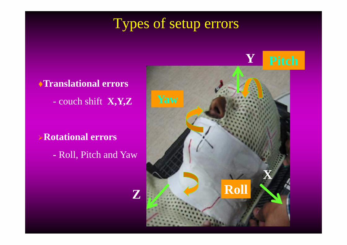
Types of setup errors
�Translational errors
- couch shiftX,Y,Z
�Rotational errors
- Roll, Pitch and Yaw
RollX
Y
Z
Pitch
Yaw

Image Registration in IGRT
� Find translation/ rotation/deformation to align two 2D..4D data sets
� Allows combination of scans on a point by point basis
Applications in radiotherapy� Improvement of target definition� Motion tracking� Image guidance of treatment� Dose accumulation
Displaying a combination of aligned images
Image Registration
Image Fusion

Automatic matching: Registration methods
Registration Simple deformable registration Full deformable registration
� Bone-match
� Soft-tissue match (gray scale)

Treatment Time for IGRT
Patient setup in the room: 2 – 5 min
kV/kV or MV/kV imaging: ~ 1 min
2D2D matching analysis 2 – 5 min
CBCT imaging: 3 min
3D3D matching analysis: 2 – 5 min
Re-positioning: ~ 1 min
Treatment delivery: 10 – 15 min
Total treatment time for with CBCT 20-35 min
Total treatment time without CBCT 15-25 min

� planar kV x-ray imaging
- maximum dose can be concentrated on the skin
�Volumetric CT dose
- distributes throughout the anatomical volume of
�Depends on
- KV
-MAs
-Others Scanning parameters
Patient dose due to IGRT

Is 5% significant?
70% have local regional diseases on presentation
100% diagnosed with cancer
30% have metastatic diseases
35% are treated with radiation or other Rx
modalities
35% are treated without radiation
25% achieve loco-regional control
10% fail with local regional recurrence
+ metastasis
5% fail due to biological cause
5% fail due to physical cause
25% achieve loco-regional control
10% fail with local regional recurrence
+ metastasisWith IMRT
Without IMRT
IGRT with biological imaging may help 5% population
Cost-Beneficial analysis
Total population is 287 million1.28 million/year will be diagnosed with cancer555,000/yr will succeeds 5% corresponds to saving over 64,000 lives/yr

Take-home messages� 2D planar vs. 3D volumetric imaging
� Pre-treatment vs. real-time motoring/tracking
� Direct target localization vs. target surrogates
� Online vs. offline adaptation
� Anatomy-based vs. dose-based adaptation

EPID Planner imaging
Interfractional Intrafractional Requires surrogate, difficult
to assess 3D information Not possible
Stereoscopic X-ray imaging Requires surrogate, 6 DOF possible Requires surrogate, 6 DOF possible, real-time target
localization possible
Ultrasound imaging NO surrogate required, limited to pathologies that can be imaged with
USNOT possible
KVCBCT Requires no surrogate, 6 DOF possible NOT possible
MVCT Requires no surrogate, 6 DOF possibleNOT possible
Optical tracking, video,….. unable to visualize target volume unable to visualize target volume
IGRT for management of Inter and intra- fraction geometric uncertainities

Getting the patient set up correctly
� CT-on-rails� KV cone beam� MV cone beam� Positioning sensors� Ultrasound� EPID with fiducials� Photography� Laser setups� Portal films
� Photography
� Ultrasound
� Positioning sensors
� Portal films
� EPID with fiducials
� CT-on-rails
� KV/MV cone beam
In order of effectiveness In order of safety

Errors and Margin� Determine what these error sources are and what their impact is
in your department
� Focus on correcting remaining systematic errors
� Image guidance systems can half the margin
� IGRT does not eliminate all errors; carefully consider the margins to be used
� IGRT introduces new errors and makes old errors more important
� Margin recipes assume that you know ALL ERRORS USE AT YOUR OWN RISK

Summary and Conclusion� Patient setup error is systematic & larger than random error
� Target delineation error remains as systematic and large error
� Tracking reduce beam on time but not considered deformation
� IGRT reduces systematic error and accurate dose delivery
� IGRT provides dose escalation and hypofraction in lung cancers
IGRT is a new technology and its clinical benefits yet to be proved

Emerging technologies
Administration Budget
Chief of Physics
Residents Dosimetrist Physician
Physicist
QA, RTPS, 4D CT, radiographic, fluoroscopic, & CBCT IGRT, image registration, fusion, US, 4D PET/CT....
Technologist