Embed Size (px)
Citation preview

PhysicsHSC Course
Stage 6
From ideas to implementation
Part 2: The amazing cathode ray tube


Part 2: The amazing cathode ray tube 1
Contents
Introduction ............................................................................... 2
Cathode ray tubes (CRT) .......................................................... 3
Types of cathode ray tube ..................................................................3
What makes up a CRT? ......................................................................4
Cathode ray oscilloscope (CRO).........................................................5
Using the CRO .....................................................................................6
Cathode ray tubes in television sets........................................ 11
Safety requirements ..........................................................................11
Inside the picture tube .......................................................................12
The picture .........................................................................................14
Controlling the cathode ray beam ....................................................19
Electron microscopes ............................................................. 22
Types of electron microscopes .........................................................22
Lightning conductors .............................................................. 27
Photocopiers .......................................................................... 29
Summary................................................................................. 31
Suggested answers................................................................. 33
Exercises – Part 2 ................................................................... 35
2 From ideas to implementation
Introduction
In the last part of this module you learned about the history of the
development of the cathode ray tube and its role as an instrument of
scientific research into the nature of subatomic particles, namely the
electron. In this part you will learn about some of the applications for the
cathode ray tube. Many of these applications directly affect daily life
and have improved our understanding of the world around us.
In Part 2 you will be given opportunities to learn to:
• outline the role in a cathode ray tube of:
– electrodes in the electron gun
– the electric field
– the fluorescent screen
• outline applications of cathode rays in oscilloscopes, electronmicroscopes and television sets
• discuss the impact of increased understanding of cathode rays andthe development of the oscilloscope on experimental physics.
In Part 2 you will be given opportunities to:
• gather, analyse and process information on the use of electrically
charged plates and point charges in photocopying machines and
lightning conductors
• gather secondary information to identify the use of magnetic fields in
television sets.
Extracts from Physics Stage 6 Syllabus © Board of Studies NSW, originally
issued 1999. The most up-to-date version can be found on the Board's website
at http://www.boardofstudies.nsw.edu.au/syllabus99/syllabus2000_list.html
Part 2: The amazing cathode ray tube 3
Cathode ray tubes (CRT)
The German scientist Karl Braun invented the cathode ray tube with a
fluorescent screen making up one end of the tube in 1897. It rapidly
became a research tool for scientist such as Thomson. Braun discovered
that a stream of electrons would make a screen coated with fluorescent
material glow with light.
Braun was the developer of the cathode ray oscilloscope. He
demonstrated the first oscilloscope tube in 1897, after research work on
high frequency alternating currents.
Cathode ray tubes previous to Braun's work had produced uncontrolled
cathode ray streams. Braun succeeded in producing a narrow stream of
electrons directed by means of alternating voltages that could trace
patterns on a fluorescent screen.
Types of cathode ray tube
CRTs are divided into two major groups based on how the electron beam
(or beams) are directed to the desired location on the tube's screen.
• CRTs where the electron beam is deflected electrostatically or by
electric fields. This system of electron beam deflection is used
primarily for oscilloscopes where great speed is required to position
the electron beam to a desired location on the screen in order to
follow rapidly changing waveforms.
• CRTs where the electron beam is electromagnetically deflected.
This type of CRT is used almost universally in television, computer
displays and radar.
The figure following shows a computer monitor CRT. Notice the copper
electromagnetic deflection coils.

4 From ideas to implementation
Computer monitor cathode ray picture tube. Photo: Ric Morante.
Color CRTs are similar to other electromagnetically deflected CRTs
except that they contain the equivalent of three conventional electron
guns in one envelope along with a more complex screen configuration in
terms of the distribution of the phosphors into discrete areas in the
fluorescing screen.
What makes up a CRT?
The basic components of all modern CRTs are outlined below.
• An electron beam source and beam intensity control mechanism.
• One or more accelerating electrodes. These increase the electron’s
velocity so that when the electrons hit the screen they have enough
energy to ensure appropriate light output from the screen. The faster
the electrons are travelling, the brighter the fluorescence produced
by the screen.
• A focusing section consisting of electric fields that bring the electron
beam to a sharp focus precisely at the screen. Most CRTs have a
curved front screen so that the focusing mechanism required by the
television produces a focused beam at the same distance from the
filament, no matter where on the screen the electron beam hits.

Part 2: The amazing cathode ray tube 5
• A deflection system consisting of magnetic coils that positions the
beam to a desired location on the screen or is used to scan the beam
across and down the screen in a repetitive pattern.
• A phosphor screen that converts the kinetic energy of the electrons
in the invisible electron or cathode ray beam into visible light.
• A mechanical structure known as the envelope or tube outer that
allows a vacuum state (eg. the glass tube). This must also provide a
location for electrical connections to the various electrodes, and must
insulate those connections and components from each other.
Why does the CRT screen glow?
The screen glows because of phosphorescence. Cathode ray tubes and
television picture tubes have a layer of the phosphor coated on the inside
of the glass screen. The beam of electrons projected by the cathode
excites the fluorescent phosphor layer on the screen. That is, the
phosphors glow.
Most cathode ray tubes use zinc sulfide that glows with a characteristic
blue-green trace. In a colour TV tube, the screen is coated with three
phosphors that fluoresce – one red, another green and the third blue.
With phosphorescence, the emission of light from a phosphorescent
substance can continue for a brief time after the exciting radiation of the
electron beam is cut off. That is why when the TV is finally turned off at
night the screen appears to have a soft glow in the darkened room for a
short time. This is because the phosphor material absorbs energy from
earlier exposure to the beam of electrons which is stored and gradually
re-emitted later as light.
Phosphorescent materials include zinc, calcium, barium and strontium
sulfides.
Cathode ray oscilloscope (CRO)
A cathode ray tube that is configured as a cathode ray oscilloscope is
shown in the figure following.

6 From ideas to implementation
1 kV potential difference
cathode
electron
grid
vertical deflection plates
horizontal deflection plates
electrons in a beam
vacuum
a bright spot is formed at thepoint where the electron beammeets this luminescent screen
filament
fluorescent screen
The internal 3-D view of a modified cathode ray tube that makes up a CRO.The deflection plates are set with positive or negative potentials with an ACcurrent. The changing electric fields across the plates can cause rapiddeflection of the electrons in the electron beam.
The stream of electrons from the cathode can be focussed to a point at the
end of the tube on a fluorescent screen by use of a device called an
electron gun. The electron gun consists of:
· a filament that is the source of electrons
· a negatively charged metal cylinder that focuses the electron beam in
much the same way as a condensing (convex) lens focuses light
· a series of metal anode cylinders that have progressively higher
positive potentials (voltages) relative to the cathode.
The beam is focussed to a dot by the use of electric fields from the anode
cylinders. The effect of the electric fields from a two anode electron gun
are illustrated in the figure following.
The invention of the cathode ray oscilloscope was the forerunner of the
television picture tube and radarscope. It also became an important
laboratory research instrument.
Braun's career in science came to an end when he travelled to New York
City in 1915 to testify in a radio related patent case. He was detained
there because of his German citizenship when the U.S. entered World
War I in 1917. He died in 1918 before the war ended. He apparently did
not contribute to the allied war effort while in detention and so was loyal
to his native Germany.

Part 2: The amazing cathode ray tube 7
F
anode 1
anode 2
equipotential lines
electron beam
screen is at thebeam focusmore positive
positive
negatively charged cylinderacts as a condensing lensto narrow the beam
electrons are emittedat the filament
An electron gun. The anodes shown in the figure are each part of a cut awaycylinder. These cylinders enable the electron beam to be focussed in crosssection to a cylindrical beam.
1 Outline the role of the electron gun in the cathode ray tube.
_____________________________________________________
_____________________________________________________
_____________________________________________________
_____________________________________________________
2 What does the cylindrical electric plates in the anodes do to the
electron beam?
_____________________________________________________
_____________________________________________________
_____________________________________________________
_____________________________________________________
3 Why is the fluorescing screen so important in the modern cathode
ray tube used in applications such as the CRO or television?
_____________________________________________________
_____________________________________________________
_____________________________________________________
_____________________________________________________
Check your answers.

8 From ideas to implementation
Using the CRO
You are already familiar with the use of the CRO to study sound waves
in the module The world communicates. This use of the CRO is not the
typical one made in research. Rather the CRO is used as a research tool
wherever low, fluctuating voltages occur. In the electronics industry that
application has guided development of the communication age in which
you currently live. This means the CRO has been used in the
development of just about every communication and computing device
known.
Locate a local electronics enthusiast or someone who professionally repairs
electronic appliances such as televisions or computers. Ask them how they
use the CRO in their work. Write down their responses in the space below.
_________________________________________________________
_________________________________________________________
_________________________________________________________
_________________________________________________________
_________________________________________________________
_________________________________________________________
_________________________________________________________
_________________________________________________________
_________________________________________________________
How does the CRO work?
The voltage to the horizontal deflection plates is adjusted so as to move
the electron beam across the screen at a constant rate. The vertical
deflection plates are subject to varying or constantly varying AC
voltages. This moves the electron beam irregularly in the vertical plane.
The combined motion produces a trace on the phosphor screen.
This is illustrated in the following where a sine wave trace is produced
on the screen of the CRO by a constant AC voltage input.

Part 2: The amazing cathode ray tube 9
zero voltage across the verticaldeflection plates
a constant DC voltage acrossthe vertical deflection plates
dot moves up (ordown) the screen
dot in the centre ofthe screen
a constant AC current across thevertical deflection platesproduces a line
spot oscillates vertically
spot moves horizontallyat steady speed
A combination of a constanthorizontal deflection and aAC deflection onthe vertical plates producesa sine curve
The trace from a CRO produced by an AC current.

10 From ideas to implementation
The trace shown above is that produced by a regular AC voltage.
The pale text at the bottom indicates that each division on the grid in the
y-direction represents 0.25 V. The time base is shown as 5.005 ms per
division of the x-direction grid.
1 Look at the figure on the previous page. What does this indicate about
the rate of movement of the electron beam across the screen in the
x-direction?
_____________________________________________________
_____________________________________________________
2 What movement of the deflection plates would produce that
movement you described above? Which deflection plates in the
CRO tube would be involved?
______________________________________________________
______________________________________________________
______________________________________________________
3 What movement of the electron beam is necessary in the y-direction
to produce the pattern shown?
______________________________________________________
______________________________________________________
4 How can this y-direction movement of the electron beam be
produced by the deflection plates in the CRO tube?
______________________________________________________
______________________________________________________
______________________________________________________
Check your answers.
Do Exercises 2.1 to 2.2 now.

Part 2: The amazing cathode ray tube 11
Cathode ray tubes in television sets
Traditional television sets contain a modified cathode ray tube as a
picture tube. The picture tube is a funnel shaped cathode ray tube made
of special glass. The glass tubes must be able to seal to the metal
electrodes that carry high voltages (the anode buttons) and to the
conductors supplying the heating power and control voltages to the
cathode. Together these form part of the electron beam gun.
electron gun
magneticdeflection
coils
silvered tubefluorescent screen
A television cathode ray picture tube.
Safety requirements
The glass used to manufacture the picture tube has specific requirements
for safety reasons. The television picture tube is essentially a particle
accelerator. Electrons are accelerated from the cathode toward the anode
and eventually the phosphor coated screen. Accelerating an electron
causes it to give out electromagnetic radiation. That happens in the
cathode ray picture tube of a television or computer monitor. The result
is often that low levels of high energy electromagnetic radiation such as
X-rays are produced.

12 From ideas to implementation
The electrons accelerated toward the screen in the picture tube are
undergoing an electrical energy (E = qV) loss and a kinetic energy gain12
2mvÊË
ˆ¯ .
People are exposed to the radiation from the television picture tubes for
extended periods of time. Because of this the glass used in the tube must
contain appropriate amounts of heavy oxides such as barium oxide, lead
oxide and strontium oxide in order to ensure potentially harmful X-rays
produced by the tube in its operation are absorbed.
Survey the number of hours the television set in your home is on per week.
Do this by simply recording the time(s) that the television is turned on and
off each day for a week. Many dwellings have the television operating for
up to 120 hours per week.
Sun Mon Tues Wed Thurs Fri Sat
AM
PM
Total hours
Consider that low levels of X-rays can be produced by television picture
tubes. The dosage of X-rays that can lead to health problems is
cumulative. If the body is exposed to excess levels of X-ray radiation it
can cause problems such as cancer.
Can you see why it is important to prepare the glass tubes that make up
the television picture tube from glass that absorbs X-rays?
Inside the picture tube
In a cathode ray picture tube, the cathode is a heated filament similar to
the filament in a normal light bulb. The cathode filament is heated in a
vacuum created inside a glass funnel shaped tube. As a result, electrons
naturally escape from the heated cathode into the vacuum of the tube.
The free electrons are negative. The anode is positive, so it attracts the
electrons given off from the cathode and accelerates them towards it.
The accelerated electrons actually pass through the hole in the anode,
overshoot and continue on a path toward the other end of the tube that
makes up the television screen.

Part 2: The amazing cathode ray tube 13
In a television’s cathode ray picture tube, the accelerating stream of
electrons (or cathode ray) is focused into a narrow beam by a set of
focusing anodes. This arrangement is again called an electron gun.
The electron gun is located at the rear of the glass discharge tube called thepicture tube. The electron gun makes the cathode ray beam that is eventuallyresponsible for painting the picture on the fluorescing screen.(Photo: Ric Morante)
The cathode ray beam flies through the vacuum in the tube until it hits
the screen at the other end of the tube. This screen is really just the end
of a cathode ray tube coated with phosphor. This phosphor coating is
concentrated in small dots or rectangles on the screen. The phosphor
glows when struck by the beam. Rapid movement of the electron beam
across and down the screen at the end of the tube produces the images
you see on the television.
If you look at the labelled photograph of the cathode ray picture tube
above you will see there is a conductive silver coating inside the tube.
This conductive coating is there to soak up the electrons that pile up at
the screen-end of the tube. Hence if you look at the inside a broken
picture tube you will see it is silver coated.
14 From ideas to implementation
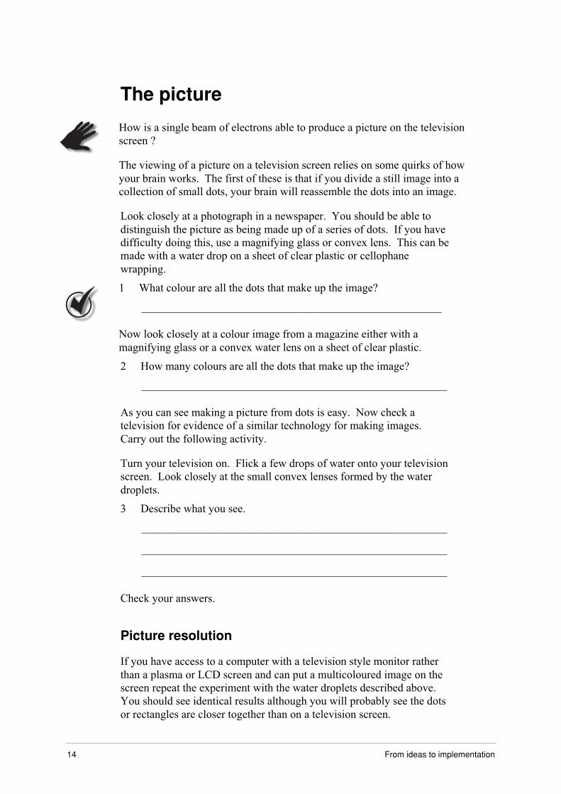
The picture
How is a single beam of electrons able to produce a picture on the television
screen ?
The viewing of a picture on a television screen relies on some quirks of how
your brain works. The first of these is that if you divide a still image into a
collection of small dots, your brain will reassemble the dots into an image.
Look closely at a photograph in a newspaper. You should be able to
distinguish the picture as being made up of a series of dots. If you have
difficulty doing this, use a magnifying glass or convex lens. This can be
made with a water drop on a sheet of clear plastic or cellophane
wrapping.
1 What colour are all the dots that make up the image?
_____________________________________________________
Now look closely at a colour image from a magazine either with a
magnifying glass or a convex water lens on a sheet of clear plastic.
2 How many colours are all the dots that make up the image?
______________________________________________________
As you can see making a picture from dots is easy. Now check a
television for evidence of a similar technology for making images.
Carry out the following activity.
Turn your television on. Flick a few drops of water onto your television
screen. Look closely at the small convex lenses formed by the water
droplets.
3 Describe what you see.
______________________________________________________
______________________________________________________
______________________________________________________
Check your answers.
Picture resolution
If you have access to a computer with a television style monitor rather
than a plasma or LCD screen and can put a multicoloured image on the
screen repeat the experiment with the water droplets described above.
You should see identical results although you will probably see the dots
or rectangles are closer together than on a television screen.

Part 2: The amazing cathode ray tube 15
This produces a higher resolution on the computer screen. The still
image allows you to examine various colours of the dots that make up the
screen colour in a particular part of the screen. You should see the dot
colour combinations vary in relative intensities. Mixing the intensities of
the different coloured dots enables the eye to construct all the colours
that can be seen on a screen.
You may be familiar with the term, dpi in printing. This refers to the
number of dots per inch. The more dots per inch the higher the
resolution of the image. A similar thing happens with computer and
television screens. The more dots per inch, the higher the resolution.
Each of the different coloured dots you see in a rectangle, stripe or dot is
made to fluoresce by an electron beam specifically aimed at that portion
of the dot. In other words there is an electron beam that is aimed only at
the red dots, another only aimed at the blue dots and a third aimed only at
the green dots. This means whereas a black and white television has a
single electron beam a colour television picture tube needs three beams.
How does the image form?
You should now know that the image formed on a television screen is
made up of a series of dots. The question you should now ask yourself is
how does a single electron beam on a white phosphor screen produce an
image in black and white, or how does three electron beams produce a
coloured image? The answer lies in another quirk of the eye.
This quirk is one you are already familiar with and probably experience
everyday. When you look at a bright light such as a light globe filament
the image of that bright object is clearly impressed on the eye for some
time even after you stop looking at the bright object. This is even more
apparent if you close your eyes after looking at the bright object. You
will still see a residual image of the bright object apparently impressed
on your eyelids.
Another example of this happening is if you spin a torch or bright light
around in a circular motion on a dark night. The passage of the torch
forms a circular ring pattern on the retina of the eye. This creates the
appearance of a ring of light even though the torch can only be in one
place at any one time.

16 From ideas to implementation
Moving pictures
The final quirk of the eye that allows you to see moving picture is as
follows.
If you photograph a moving object a number of times in close
succession, a sequence of still pictures is produced. If you show the still
pictures in rapid succession, your brain reassembles the sequence of still
pictures back into a moving scene.
You don’t have to be special to do this. In fact, cartoons and all
animations are based on this concept. You may even have tried to
produce your own animation using something as simple as stick figures
on the corners of the pages of a book that you can flick through rapidly to
give the stick figures an appearance of motion. If you have never tried
this you should have a go now with the corners of the page of the
learning materials.
Watching motion
If you have access to a video cassette recorder (VCR) and a tape try the
following activity.
1 Put a recorded video in your VCR.
2 Press play.
3 Press pause and advance the video by the frame advance if the VCR has
that option.
Can you see the individual frames that are assembled and played one
after the other to produce the effect of a moving image from still frames
taken close together? If the frames are flicking through and changing
fast enough your brain and eyes do not seen any of these individual
frames. You see a moving picture scene.
A clear picture
The bright spot left by the moving electron beam in the cathode ray tube
moves across and down the screen many times per second (50 times for
most televisions but can be higher for example 100 times or 100 Hz for
flicker free televisions). Everywhere it touches the phosphor screen the
screen fluoresces. The result is a picture produced on the retina of your
eye of the pattern arced out by the bright spot on the screen.
This picture appears to be on the screen of the cathode ray picture tube
even though in reality each electron beam is only causing illumination at
one point on the screen at any one instant of time.

Part 2: The amazing cathode ray tube 17
To assist this process there is also a slight lag time where the
fluorescence of the screen is maintained even though the electron beam
moves on. However, the length of this lag time glow must be short to
produce a clear picture and avoid interference.
Instead of deflection plates, steering coils produce the movement of the
electron beam within the cathode ray tube. Steering coils are copper
windings around the outside of the tube. These current carrying coils
create magnetic fields inside the tube when an electric current passes
through them. The electron beam is deflected by the magnetic fields.
One set of steering coils creates a magnetic field that pushes the electron
beam down the screen (the vertical deflection plates of the electron gun).
Another set of steering coils creates the magnetic fields that push the
beam horizontally (the horizontal deflection plates of the electron gun).
A computer monitor showing deflection coils. (Photo: Ric Morante.)
By controlling the size and direction of the currents flowing in the coils
you can position the electron beam to any point on the screen.
In a television picture tube, to paint the entire screen and trick the eye
into seeing this illumination as a constantly repainted moving picture, the
magnetic field generated by the current carrying coils to need to move
the electron beam in a ‘raster scan’ pattern across and down the screen.
In other words, the beam paints one line across the screen from left to
right.

18 From ideas to implementation
These lines are rows of dots of different brightness varying with the
intensity of the electron beam. At the end of a line the beam is switched
off then quickly turned back on when aimed at the left hand side of the
screen again but has been pushed down screen slightly. It then ‘paints’
another horizontal line and the whole process is repeated. This continues
down the screen until the entire screen has been painted. The electron
beam is then switched off until it is aimed at the top left hand corner
again ready to begin repainting the screen once more. The whole screen
is painted 50 times per second to produce the effect of a moving picture
scene.
If the television is a 100 Hz model the process described above is
repeated 100 times per second. The more times per second the screen is
painted, the greater the flicker free effect of the picture. Manufacturers
of televisions claim this flicker free television is less demanding on the
eyes and promotes more comfortable viewing. These 100 Hz televisions
are not as common as 50 Hz televisions because of their higher cost.
Computer monitors that work in almost the identical manner are often
designed so that the screen is painted in excess of 50 times per second to
produce higher resolution flicker free images. Some computer monitors
allow you to change the refresh or repaint rate of the monitor to suit your
own requirements up to around 100 Hz. Interestingly most video cassette
machines send the signal to the television for repainting the picture only
25 times per second yet the picture is relatively flawless and appears
continuous.
1 Seek out a 50 Hz television, a 100 Hz television, a television playing a
video tape and a high resolution computer monitor. This may be most
easily accomplished by visiting an electrical goods shop.
Compare the image in terms of viewing quality. Write down your
impressions as to whether you can tell the difference or see the
flickering of the image.
______________________________________________________
______________________________________________________
______________________________________________________
______________________________________________________
2 Watch television until you see a shot of a working television on the
screen. This often happens during the news. Observe the image of
the screen of the television on your screen. Do you notice the
definite flicker?
Alternatively if you have access to a video camera take a video of
the screen of an operating television. Replay the video though your
television. You should see the image of the screen flicker.

Part 2: The amazing cathode ray tube 19
Why is this flickering of the television screen image visible to you much
more prominently in the video footage even though if you were watching the
television you wouldn't notice the flicker?
_________________________________________________________
_________________________________________________________
_________________________________________________________
Check your answer.
Controlling the cathode ray beam
In the module The world communicates you learned that a signal is
necessary to produce a response in the electronic communication devices.
When a television aerial receives a broadcast radio signal, or when you
use a video cassette recorder (VCR) or digital video disc player (DVD) to
play a program on your television, the signal has to contain the
information to control the electron beams in the cathode ray picture tube.
That is the signal needs to contain the information that tells the
electronics controlling the beams of electrons hitting the phosphor screen
how to behave. This is so that the image on the phosphor screen is
accurate to the one the TV station, DVD or VCR sends.
The TV station or VCR therefore sends a signal to the TV that contains
four different parts.
• Intensity signals for the electron beam as it paints each line. This
controls the brightness of the glow on the phosphor screen to enable
shading on the image.
• Horizontal retrace signals the TV when to move the electron beam
very quickly back at the end of each line.
• Vertical retrace signals to move the beam from bottom right to top
left in conjunction with the horizontal.
• A signal indicates which of the electron beams aimed at the coloured
phosphor dots on the screen should be turned on or off to illuminate
phosphors necessary to make the colour required in that part of the
screen.
A signal that contains all of these components is called a composite
video signal. Of course that signal will only give you the picture. The
sound is produced by the decoding of a simultaneously transmitted FM
audio signal! Note that both signals are radio frequencies.
20 From ideas to implementation
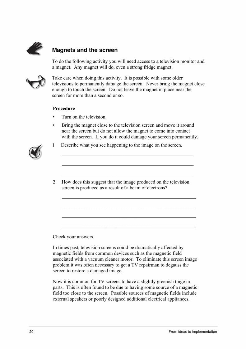
Magnets and the screen
To do the following activity you will need access to a television monitor and
a magnet. Any magnet will do, even a strong fridge magnet.
Take care when doing this activity. It is possible with some older
televisions to permanently damage the screen. Never bring the magnet close
enough to touch the screen. Do not leave the magnet in place near the
screen for more than a second or so.
Procedure
• Turn on the television.
• Bring the magnet close to the television screen and move it around
near the screen but do not allow the magnet to come into contact
with the screen. If you do it could damage your screen permanently.
1 Describe what you see happening to the image on the screen.
_____________________________________________________
_____________________________________________________
_____________________________________________________
2 How does this suggest that the image produced on the television
screen is produced as a result of a beam of electrons?
______________________________________________________
______________________________________________________
______________________________________________________
______________________________________________________
Check your answers.
In times past, television screens could be dramatically affected by
magnetic fields from common devices such as the magnetic field
associated with a vacuum cleaner motor. To eliminate this screen image
problem it was often necessary to get a TV repairman to degauss the
screen to restore a damaged image.
Now it is common for TV screens to have a slightly greenish tinge in
parts. This is often found to be due to having some source of a magnetic
field too close to the screen. Possible sources of magnetic fields include
external speakers or poorly designed additional electrical appliances.

Part 2: The amazing cathode ray tube 21
It is now common for computer monitors to have a built in adjustment
that allows you to degauss the screen should it be affected by a stray
magnetic field by accident. Other devices such as televisions are
degaussed when you switch the television of and on.
Locate a TV repairman and ask about the role of magnetic fields in
producing a clear picture on the television screen.

22 From ideas to implementation
Electron microscopes
Almost everyone has looked at photographs taken by an electron
microscope. Usually these photographs show exquisite detail of very
small objects. What most people do not realise is that the electron
microscope is really behaving as a giant cathode ray tube. The main
difference between an electron microscope and a light microscope is the
way that the device forms images. The electron microscope uses a
stream of electrons instead of a stream of light photons to form the
image. So, electron microscopes are really just scientific instruments that
use a beam of highly energetic electrons to examine objects on a very
fine scale.
Electron microscopes were developed to overcome the magnification andresolution limitations of the light microscopes. Light microscopes are
limited by the physics of light to 500X or 1000X magnification and have
a resolution limit of 0.2 mm.
The problem is that resolution is determined by the wavelength of theradiation being employed.
By the early 1930s these limits had been achieved. The desire to seefiner detail was expanding with biologists seeking to see the interior
structures of cells and the structure of the cell membrane. To see moredetail required resolution and magnification at least ten times greater than
could be supplied by the light microscope.
The size of electron vibrations is tiny compared to the wavelength of
light. This means a greater resolving power for the electron microscope.The aim was, therefore, to build an electron microscope.
Types of electron microscopes
There are two basic types of electron microscopes: the transmission
electron microscope (TEM) and the scanning electron microscope
(SEM).

Part 2: The amazing cathode ray tube 23
The transmission electron microscope (TEM) was the first type of
electron microscope to be developed. It was developed by Max Knoll
and Ernst Ruska in Germany in 1931. Its mode of operation was
patterned on the light transmission microscope you are most probably
familiar with. The difference is that a focused beam of electrons was
used to 'see' through the specimen rather than light.
The first experimental scanning electron microscope (SEM) operated in
1942 but the first commercial instruments didn't become available until
around 1965. A scanning electron microscope works in much the same
way as a light reflection microscope except that instead of the image
forming from reflected light the image forms from reflected electrons.
All electron microscopes work in basically the same way.
1 A stream of electrons is formed by a cathode filament and
accelerated toward and through an anode toward the specimen in a
vacuum tube.
2 The electron stream or cathode ray is focused using metal apertures
and electromagnetic lenses into a thin, focused beam. The metal
apertures simply stop any stray electrons from outside the main
beam interfering with the production of a clear image. The role of
these devices is similar to the electron gun in a television or CRO.
3 The cathode ray beam is focused onto the sample using an
electromagnetic lens. In general the beam scans across and down the
specimen.
4 Interactions occur between the electrons and the specimen. These
directly affect the electron beam transmission or reflection and it is
this alteration in the electron beam that is detected and transformed
into an image on a phosphor screen.
The transmission electron microscope
This type of microscope is generally used to examine biological
specimens. The microscope is essentially a sealed vacuum tube. Heating
a tungsten filament at voltages usually at around 500 V produces the
cathode or electron source. Then the electrons are accelerated at voltages
generally ranging from 60 000 to 100 000 V. This high voltage
accelerates the electrons toward the anode with the result that the
electrons pass through the specimen. For the electrons to pass through
the sample it must be cut very thin.
Because electron beams are invisible to the eye, the images they form are
revealed on a fluorescent phosphor screen that is essentially a high
resolution black and white television screen and can then be
photographed.

24 From ideas to implementation
To increase the contrast in the thin sample it is stained with electron
absorbing heavy metal salts that are preferentially absorbed in some parts
of the specimen. The sample is loaded into a chamber at normal air
pressure. The chamber is attached to a vacuum pump and the whole
system is evacuated before the electron beam can begin to ‘look’ at the
sample.
filament acting as a cathode
magnetic field
electromagnets acting asa condenser lens system
system under vacuum
magnetic fields refocus thebeamand act as an objectivelens
sample cut thinly
electron beam hits aphosphor screen andforms a magnifiedimage just like animage on a televisionscreen
phosphor screen
electron beam thatpases through thethin sample
the person viewsthe light imagethat forms on thephosphor screen
light image from thephosphor screen
condenser ringaperture tocollect strayelectrons
projector lens magnetic fields
The transmission electron microscope.
The first lens largely determines the ‘spot size’ – the general size range
of the final spot that strikes the sample. The second lens changes the size
of the spot on the sample; changing it from a wide dispersed spot to a
pinpoint beam.
A condenser ring is used to prevent any stray electrons that are not part
of the tight beam hitting the object and producing a fuzzy halo on the
image. This also restricts the electron beam.
The tightly focussed beam strikes the specimen. Some of the beam is
directly transmitted, while some is absorbed or scattered. The transmitted
portion is focused by the objective lens to form an image that is passed
down the tube through intermediate and projector lenses. These lenses
have the role of enlarging the image before it forms on the phosphor
screen.
Part 2: The amazing cathode ray tube 25
At the phosphor screen the energy of the moving electrons is converted
into light. This allows the user to see the image or photograph it.
Darker areas of the image represent those that fewer electrons were
transmitted through because they were thicker or denser. This is aided
by the contrast enhancing chemicals mentioned earlier.
Lighter areas of the image represent areas of the sample that more
electrons were transmitted through because they were thinner or less
dense or absorbed less by less of the electron absorbing salts.
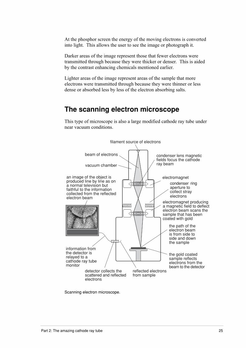
The scanning electron microscope
This type of microscope is also a large modified cathode ray tube under
near vacuum conditions.
filament source of electrons
condenser lens magneticfields focus the cathoderay beam
electromagnet
electromagnet producinga magnetic field to deflectelectron beam scans thesample that has beencoated with gold
beam of electrons
an image of the object isproduced line by line as ona normal television butfaithful to the informationcollected from the reflectedelectron beam
vacuum chamber
information fromthe detector isrelayed to acathode ray tubemonitor
detector collects thescattered and reflectedelectrons
reflected electronsfrom sample
the path of theelectron beamis from side toside and downthe sample
the gold coatedsample reflectselectrons from thebeam to the detector
condenser ringaperture tocollect strayelectrons
Scanning electron microscope.
26 From ideas to implementation
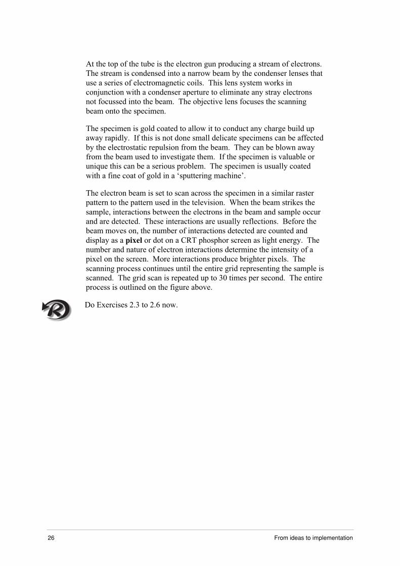
At the top of the tube is the electron gun producing a stream of electrons.
The stream is condensed into a narrow beam by the condenser lenses that
use a series of electromagnetic coils. This lens system works in
conjunction with a condenser aperture to eliminate any stray electrons
not focussed into the beam. The objective lens focuses the scanning
beam onto the specimen.
The specimen is gold coated to allow it to conduct any charge build up
away rapidly. If this is not done small delicate specimens can be affected
by the electrostatic repulsion from the beam. They can be blown away
from the beam used to investigate them. If the specimen is valuable or
unique this can be a serious problem. The specimen is usually coated
with a fine coat of gold in a ‘sputtering machine’.
The electron beam is set to scan across the specimen in a similar raster
pattern to the pattern used in the television. When the beam strikes the
sample, interactions between the electrons in the beam and sample occur
and are detected. These interactions are usually reflections. Before the
beam moves on, the number of interactions detected are counted and
display as a pixel or dot on a CRT phosphor screen as light energy. The
number and nature of electron interactions determine the intensity of a
pixel on the screen. More interactions produce brighter pixels. The
scanning process continues until the entire grid representing the sample is
scanned. The grid scan is repeated up to 30 times per second. The entire
process is outlined on the figure above.
Do Exercises 2.3 to 2.6 now.

Part 2: The amazing cathode ray tube 27
Lightning conductors
Lightning protection systems are designed to prevent damage to people
and property due to a large electrical discharge of static electricity that
has built up in clouds. The discharges can be of the order of 200 000 A.
The diagram below shows a typical lightning protection system on a
domestic dwelling.
lightning rods
conductingcopper wire
metal strapgrounding plates andground termination rods
A domestic dwelling with a lightning protection system installed.
The main purpose of the system is to conduct the electrical charge of a
lightning strike safely away from property and people along a designated
path. Hopefully, the system intercepts and guides the electric current
harmlessly to ground.
A typical domestic lightning protection system is made up of several
components:
• Air terminals or lightning rods: These are usually slender metal rods
that are installed on the roof at regular intervals. In the past these
rods were always pointed though new research suggests that blunt
rods may be better suited as lightning rods.

28 From ideas to implementation
• Conductors: These are usually copper cables that connect the air
terminals and the other system components.
• Ground terminations: These are metal rods driven into the earth to
guide the lightning current harmlessly to ground where it will
dissipate. These rods may be attached to a metal sheet or plate to
make the dissipation of the electric current more efficient.
In large buildings or installations of a commercial nature, such as
communications dishes, a conductive strap of metal may be used to
ensure that the current is spread evenly over a number of ground
terminations. These ground terminations are often buried up to 3 m
below the surface in trenches. This reduces the danger to people and
equipment that may be close to the ground termination when there is
a lightning strike.

Part 2: The amazing cathode ray tube 29
Photocopiers
Most photocopiers receive their information one page at a time and print
using electrostatic charges, toner and laser light. The actual way
individual copiers work varies a lot. The description that follows is an
outline of a possible pathway by which a photocopier may operate.
Photocopying involves the application of electrostatic charges and heat to
produce copies of all kinds of written, printed and graphic matter. The
basis of the photocopying process is photoconductivity.
Photoconductivity is the ability of certain substances to allow an electric
current to flow through them when struck by light. The chemical
element, selenium is a photoconductive material. It is a poor electrical
conductor in low light levels but, when light energy is absorbed by some
of the selenium’s electrons and a voltage is applied, the conductivity of
the selenium increases. This occurs because electrons are able to pass
more freely from one atom to another after absorbing the light energy.
When the light source is removed, the electron mobility falls and the
selenium becomes a non-conductor again.
A photocopier uses an aluminum drum coated with a layer of selenium.
The light from the document to be copied is reflected from its surface to
the selenium surface of the copier drum.
Particles of toner are sprayed through a nozzle, gain a negative charge
and stick to the drum in the dark areas where no reflection from the
original occurred. This is the print or picture. In doing so this forms an
image of the document on the drum that is reversed as when viewed in a
mirror.
A sheet of copy paper is passed close to the rotating drum. A positive
electrically charged plate under the paper causes the negatively charged
toner to move across to the copy paper. The toner is then sealed to the
paper by a hot roller that fuses the toner particles to the paper. Voila, a
copy!

30 From ideas to implementation
The process of making a copy in the machine is as follows.
• The selenium coated drum is cleaned of any excess toner from the
surface with a rubber blade as it rotates.
• The drum is given a negative charge of about 600 V.
• A light beam passes over the paper copy from one end to the other in
a band. The reflection increases the conductivity in the lighted areas
of the drum. This causes portions of the drum not illuminated by
reflected light (dark areas of the original) to become more positively
charged.
• Toner particles made negative so they act as point charges as they
pass out of their cartridge are applied to the rotating drum and are
attracted to the areas of positive charge.
The negative areas of the drum that have been illuminated repel the
negatively charged toner particles. The surface of the drum at this
point is acting as a rotating charged plate.
As the selenium coated drum rotates out of the illuminated area it
loses its conductive and positive charged areas. This means the
toner in contact with the drum is held only weakly to the surface
because there is no longer a strong electrostatic attraction.
• The paper is fed by rollers under the rotating drum where a large
positively charged plate attracts the negatively charged toner from
the drum surface to the paper.
The drum turns as the paper runs beneath it so the toner mirror
image is transferred from the drum to the paper as a replica of the
original. The paper runs through the fusing roller that is heated to
about 200°C. This fuses the toner onto the paper.
Do Exercise 2.7 now.
If you have a access to a photocopier open the front cover and look at the
drum, the positive plate where the paper picks up the toner, the fusing roller
and the toner cartridge. Do not touch, look only, and have someone who
knows about photocopiers show you the different parts.

Part 2: The amazing cathode ray tube 31
Summary
Electrodes in the electron gun are used to: _______________________
_________________________________________________________
_________________________________________________________
_________________________________________________________
Electric fields in cathode ray tubes: ____________________________
_________________________________________________________
_________________________________________________________
_________________________________________________________
_________________________________________________________
The fluorescent screen in a cathode ray:_________________________
_________________________________________________________
_________________________________________________________
_________________________________________________________
The most common use for cathode ray tubes is in the:______________
_________________________________________________________
Oscilloscopes are sensitive to: ________________________________
_________________________________________________________
_________________________________________________________
Oscilloscopes have applications such as: ________________________
_________________________________________________________
_________________________________________________________

32 From ideas to implementation
A photocopier works by: _____________________________________
_________________________________________________________
_________________________________________________________
_________________________________________________________
_________________________________________________________
_________________________________________________________
_________________________________________________________
_________________________________________________________
_________________________________________________________

Part 2: The amazing cathode ray tube 33
Suggested answers
Cathode ray oscilloscope (CRO)1 The electron gun produces a focused cathode ray beam that is
accelerated toward the fluorescent screen using a system of electric
fields. The electron beam is aimed at different sections of the screen
using either electric or magnetic fields.
2 The electric cylindrical plates attract the beam toward the screen
giving the beam particles kinetic energy and a rapid response time
when the beam must be moved on to new spot.
3 The screen converts the energy of the electron beam into light
energy that is easy to detect with the human eye.
How does the CRO work?1 The rate of movement in the x-direction is at a constant rate until it
snaps back.
2 Horizontal deflection plates provided a constant electric field. When
the end of the display is reached the beam must switch off and
repaint the screen.
3 The movement of the electron beam is varying in the up and down
direction.
4 The y-direction movement is produced by the vertical deflection
plates given a varying voltage.
Inside the picture tube1 The dots are all black. By varying their density in any area an image
can be built-up.
2 You will see that what appears to be a solid colour is actually made
up of separate dots of colour. The dots are all one of four colours.
Those colours are cyan, magenta, yellow, blue and black.

34 From ideas to implementation
3 You should see small rectangles or circles. If the television is a
coloured television you should see these dots are red, blue or green.
If the television is a black and white television you should see the
dots are only black or white.
A clear picture
The sequencing of the refresh rates on the screen are not synchronous so
the image is only captured occasionally (relatively speaking) by the video
tape. The result is a longer than expected blank screen. If this is long
enough it appears as an annoying flicker on the taped TV monitor.
Magnets and the screen1 The image seems to distort. The screen may get a greenish tinge.
The image appears to be deflected or distorted by the effect of the
magnetic field.
2 Electrons are deflected by a magnetic field. The distortion of the
screen image suggests that whatever is producing the image is
deflected by a magnetic field.
Part 2: The amazing cathode ray tube 35
Exercises – Part 2
Exercises 2.1. to 2.7 Name: _________________________________
Exercise 2.1
�?796A5<<96A9N=7567NDC@5A;<DC<F7>99:7P9C76@;:F5?>7C=>;<DC<F7P<;A@;D@5?>
B9<@D>=675?7=<=A@C5AD<7A5CA;5@679C7=<=A@C9?5A7=E;5N8=?@H77�P@=C7A9?65:=C5?>
49Q7@4=796A5<<96A9N=7Q9CK6I7NC9N96=7C=D69?67Q4F7@4567@99<7649;<:7G=769
;6=P;<7P9C7@4567N;CN96=H
}}}}}}}}}}}}}}}}}}}}}}}}}}}}}}}}}}}}}}}}}}}}}}}}}}}}}}}}}
}}}}}}}}}}}}}}}}}}}}}}}}}}}}}}}}}}}}}}}}}}}}}}}}}}}}}}}}}
}}}}}}}}}}}}}}}}}}}}}}}}}}}}}}}}}}}}}}}}}}}}}}}}}}}}}}}}}
}}}}}}}}}}}}}}}}}}}}}}}}}}}}}}}}}}}}}}}}}}}}}}}}}}}}}}}}}
}}}}}}}}}}}}}}}}}}}}}}}}}}}}}}}}}}}}}}}}}}}}}}}}}}}}}}}}}
}}}}}}}}}}}}}}}}}}}}}}}}}}}}}}}}}}}}}}}}}}}}}}}}}}}}}}}}}
}}}}}}}}}}}}}}}}}}}}}}}}}}}}}}}}}}}}}}}}}}}}}}}}}}}}}}}}}
}}}}}}}}}}}}}}}}}}}}}}}}}}}}}}}}}}}}}}}}}}}}}}}}}}}}}}}}}
}}}}}}}}}}}}}}}}}}}}}}}}}}}}}}}}}}}}}}}}}}}}}}}}}}}}}}}}}
}}}}}}}}}}}}}}}}}}}}}}}}}}}}}}}}}}}}}}}}}}}}}}}}}}}}}}}}}

36 From ideas to implementation
Exercise 2.2
Outline the sequence of events that led to the development of the CRO
with particular reference to the development of an increased
understanding of cathode rays.
_________________________________________________________
_________________________________________________________
_________________________________________________________
_________________________________________________________
_________________________________________________________
_________________________________________________________
_________________________________________________________
Exercise 2.3
The cathode ray tube in an oscilloscope, television and electron
microscope have a number of features in common. List the common
features. Describe the common role each feature has in the operation of
the device.
_________________________________________________________
_________________________________________________________
_________________________________________________________
_________________________________________________________
_________________________________________________________
_________________________________________________________
_________________________________________________________
_________________________________________________________
_________________________________________________________
_________________________________________________________
_________________________________________________________

Part 2: The amazing cathode ray tube 37
Exercise 2.4
Describe how the magnetic fields used in television sets control the
production of the image.
_________________________________________________________
_________________________________________________________
_________________________________________________________
_________________________________________________________
_________________________________________________________
Exercise 2.5
What is the role of the electron gun in a television?
_________________________________________________________
_________________________________________________________
_________________________________________________________
Exercise 2.6
An image can be created on the screen of a black and white television
even though the size of the dot produced by the electron beam at any
instant of time is at a maximum the size of a pin head.
Explain how this is possible by referring to the characteristics of the
screen and the human eye. Discuss the role of magnetic fields in making
the image possible in your answer.
_________________________________________________________
_________________________________________________________
_________________________________________________________
_________________________________________________________
_________________________________________________________
_________________________________________________________
_________________________________________________________

38 From ideas to implementation
Exercise 2.7
The transfer of an image from the drum of a photocopier to the paper is
an example of use of electrostatic charges on extremely fine powder
particles of toner and charged plates. Outline the main features of that
process that involve the use of electrostatics.
_________________________________________________________
_________________________________________________________
_________________________________________________________
_________________________________________________________
_________________________________________________________
_________________________________________________________


![[PHYSICS, CHEMISTRY & MATHEMATICS] PART A PHYSICS](https://img.pdfslide.net/doc/110x75/61ffccc96fcd340f94038045/physics-chemistry-amp-mathematics-part-a-physics.jpg)