Embed Size (px)
Citation preview

Physics of laser-driven and beam-driven plasma accelerators
Carl B. Schroeder
USPAS 2011
Hampton, VA
Office of Science
Supported by the Office of High Energy Physics, Office of Science, U.S. DOE under Contract No. DE-AC02-05CH11231
(similarities & differences, comparable & contrasting features, lasers or beams?)

Plasma-based accelerators for future colliders
2
• PWFA-linear collider: • two-beam accelerator geometry • 25 GeV drive beams • 19 plasma stages (1 TeV) • n=1017 cm-3 (set by 30 um driver
bunch length)
• LPA-linear collider: • 50 stages (1 TeV collider) • 10 GeV/stage • requires ~10 J laser (at tens of kHz, hundreds of kW) • n=1017 cm-3 (set by laser
depletion)
Leemans & Esarey, Physics Today (2009)
Schroeder et al., PRSTAB (2010)
Seryi et al., Proc. PAC (2009)

Plasma wave excitation Transverse wake structure
Beam-driver - space-charge fields: extends plasma skin depth Laser-driver - local ponderomotive force: extends laser spot size
Regimes of operation: quasi-linear and non-linear Energy gain: operational plasma density
Driver propagation in plasma Driver diffraction/divergence, self-guiding, and head-erosion Plasma wave phase velocity ~ driver propagation velocity
Slippage - taper for laser-driven plasma waves Self-trapping for low phase velocities
Driver-plasma coupling Staging for high-energy physics
3
Outline

€
∂ 2
∂t 2+ω p
2⎛
⎝ ⎜
⎞
⎠ ⎟ nn0
= −ω p2 nbeamn0
+ c 2∇2 a2
2
Plasma wave: electron density
perturbation
Ponderomotive force (radiation pressure)
Common features: Wave excitation efficient for driver duration ~ plasma period Bucket size ~ plasma wavelength: Large waves excited for nbeam/n0 ~1 or a~1
Characteristic accelerating field:
Phase velocity of wave determined by driver velocity
λp =2πc/ωp= (πre-1/2 ) np
-1/2 ~10-100 µm
€
E ~mcω p
e⎛
⎝ ⎜
⎞
⎠ ⎟ ≈ 96V/m( ) n0[cm
-3]
Plasma acceleration: ultrahigh accelerating gradients
Space-charge force of particle beam
€
nn0
€
nbeam
n0, a
2
2
4
€
a =eAmc 2
∝ λI1/ 2
€
ω pt
Tajima & Dawson, PRL (1979) Chen et al., PRL (1985)
Transverse wakefield structure
Beam driver (a=0)
Wakefields of a narrow bunch (kprb<<1) will extend to skin depth ~kp
-1
€
Ez
E0= −kp
3 dξ'∫ cos kp (ξ − ξ')[ ] r'dr'∫ I0(kpr<)K0(kpr>)nbn0
kpr
kp(z-ct)
r~1/kp
kprb=0.05
Keinigs & Jones, Phys. Fluids, (1987)
rb
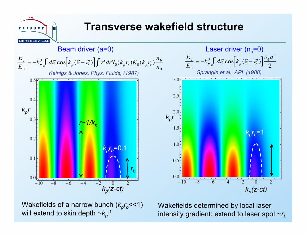
Transverse wakefield structure
Laser driver (nb=0)
Wakefields determined by local laser intensity gradient: extend to laser spot ~rL
€
Ez
E0= −kp
3 dξ'∫ cos kp (ξ − ξ')[ ]∂ξa2
2
kpr
kp(z-ct)
kprL=1
Sprangle et al., APL (1988)
Beam driver (a=0)
Wakefields of a narrow bunch (kprb<<1) will extend to skin depth ~kp
-1
€
Ez
E0= −kp
3 dξ'∫ cos kp (ξ − ξ')[ ] r'dr'∫ I0(kpr<)K0(kpr>)nbn0
kpr
kp(z-ct)
r~1/kp
kprb=0.1
Keinigs & Jones, Phys. Fluids, (1987)
rb
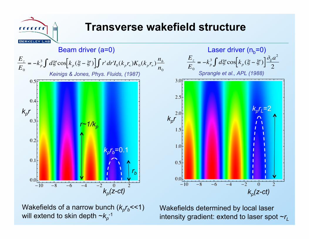
Transverse wakefield structure
Laser driver (nb=0)
Wakefields determined by local laser intensity gradient: extend to laser spot ~rL
€
Ez
E0= −kp
3 dξ'∫ cos kp (ξ − ξ')[ ]∂ξa2
2
kp(z-ct)
kprL=2
Sprangle et al., APL (1988)
kpr
Beam driver (a=0)
Wakefields of a narrow bunch (kprb<<1) will extend to skin depth ~kp
-1
€
Ez
E0= −kp
3 dξ'∫ cos kp (ξ − ξ')[ ] r'dr'∫ I0(kpr<)K0(kpr>)nbn0
kpr
kp(z-ct)
r~1/kp
kprb=0.1
Keinigs & Jones, Phys. Fluids, (1987)
rb
8
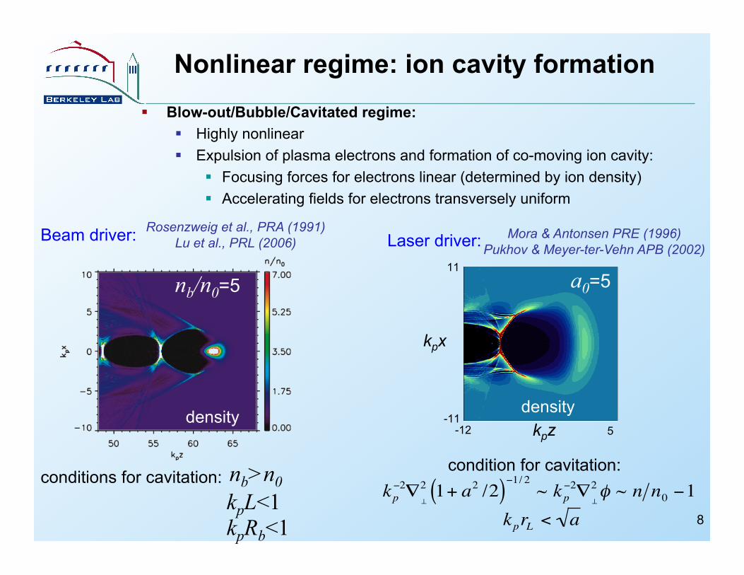
Blow-out/Bubble/Cavitated regime: Highly nonlinear Expulsion of plasma electrons and formation of co-moving ion cavity:
Focusing forces for electrons linear (determined by ion density) Accelerating fields for electrons transversely uniform
Nonlinear regime: ion cavity formation
Beam driver:
density
nb/n0=5
conditions for cavitation: nb>n0 kpL<1 kpRb<1
Rosenzweig et al., PRA (1991) Lu et al., PRL (2006)
condition for cavitation:
€
kprL < a
density
a0=5
Laser driver:
€
kp−2∇
⊥
2 1+ a2 /2( )−1/ 2 ~ kp−2∇⊥
2φ ~ n n0 −1
Mora & Antonsen PRE (1996) Pukhov & Meyer-ter-Vehn APB (2002)
kpx
kpz
11
-11 -12 5
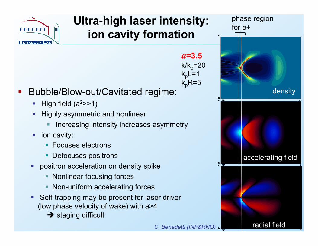
9
Bubble/Blow-out/Cavitated regime: High field (a2>>1) Highly asymmetric and nonlinear
Increasing intensity increases asymmetry ion cavity:
Focuses electrons Defocuses positrons
positron acceleration on density spike Nonlinear focusing forces Non-uniform accelerating forces
Self-trapping may be present for laser driver (low phase velocity of wake) with a>4
staging difficult
density
accelerating field
radial field
Ultra-high laser intensity: ion cavity formation
a=3.5 k/kp=20 kpL=1 kpR=5
phase region for e+
C. Benedetti (INF&RNO)
10
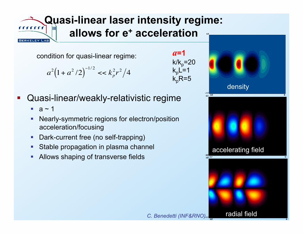
Quasi-linear/weakly-relativistic regime a ~ 1 Nearly-symmetric regions for electron/position
acceleration/focusing Dark-current free (no self-trapping) Stable propagation in plasma channel Allows shaping of transverse fields
Quasi-linear laser intensity regime: allows for e+ acceleration
density
accelerating field
radial field
a=1 k/kp=20 kpL=1 kpR=5
€
a2 1+ a2 /2( )−1/ 2 << kp2r2 4
condition for quasi-linear regime:
C. Benedetti (INF&RNO)
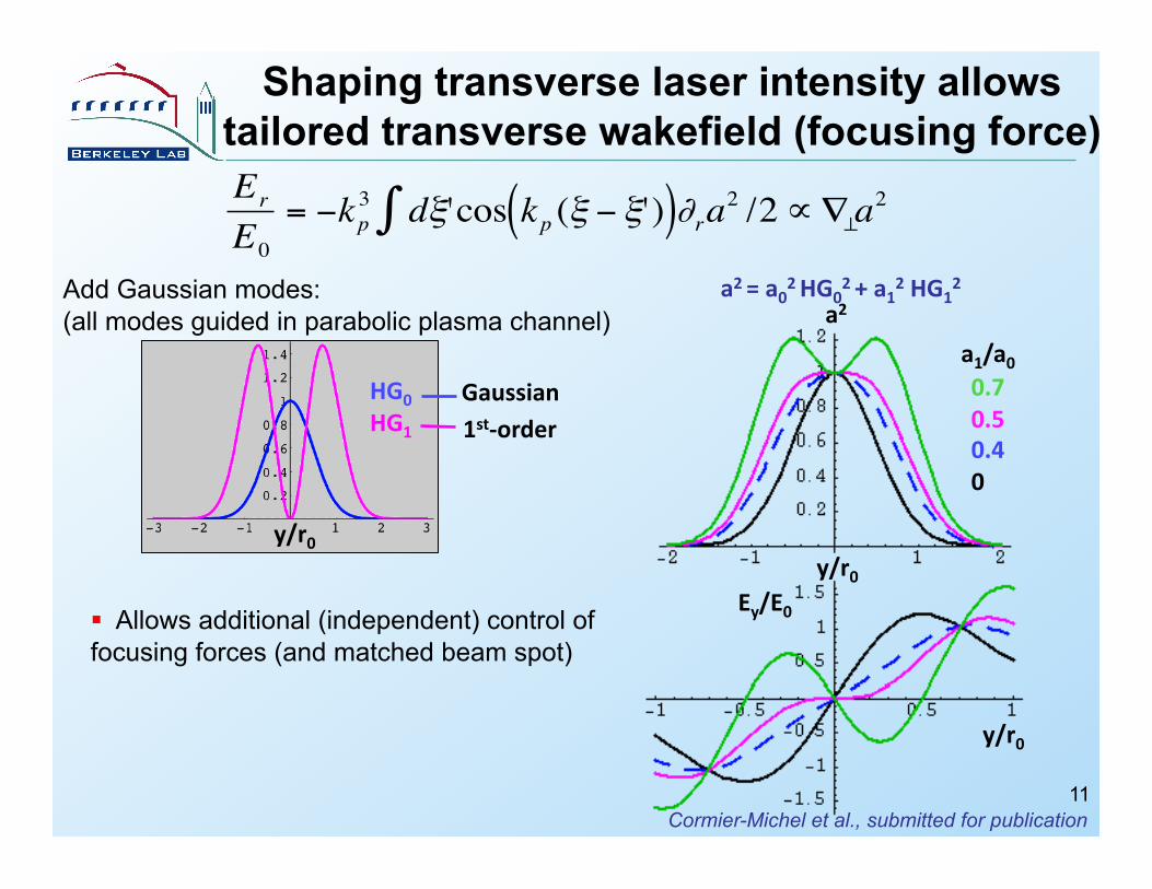
Shaping transverse laser intensity allows tailored transverse wakefield (focusing force)
y/r0
Gaussian 1st-‐order
HG0
HG1
y/r0
a2
0.7 0.5 0.4 0
a1/a0
a2 = a02 HG02 + a12 HG1
2
Ey/E0
y/r0
11
€
Er
E0= −kp
3 dξ'∫ cos kp (ξ − ξ')( )∂ra2 /2∝∇⊥a2
Add Gaussian modes: (all modes guided in parabolic plasma channel)
Allows additional (independent) control of focusing forces (and matched beam spot)
Cormier-Michel et al., submitted for publication

Subject to filamentation instability:
Growth rate:
Broad beam-driver allows shaping transverse fields of beam-driven wake
12
Shaping transverse field of beam driver requires beam transverse size to be many plasma skin depths: kprb>>1
Return current flows in beam:
kprb>>1
kpLb~1
electron return current
€
kpΓ ~nbn0γ b
⎛
⎝ ⎜
⎞
⎠ ⎟
1/ 2
Keinigs & Jones, Phys. Fluids, (1987); Bret (2009)
kprb=2π kpLb=21/2
40
-40 5 -5
C. Benedetti (INF&RNO) kpz
kpr
€
ω pt = γ bn0 np
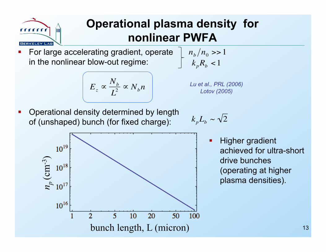
Operational plasma density for nonlinear PWFA
€
Ez ∝Nb
L2∝ Nbn €
nb n0 >>1
€
kpLb ~ 2
n p (c
m-3
)
bunch length, L (micron)
Lu et al., PRL (2006) Lotov (2005)
Higher gradient achieved for ultra-short drive bunches (operating at higher plasma densities).
For large accelerating gradient, operate in the nonlinear blow-out regime:
Operational density determined by length of (unshaped) bunch (for fixed charge):
13
€
kpRb <1
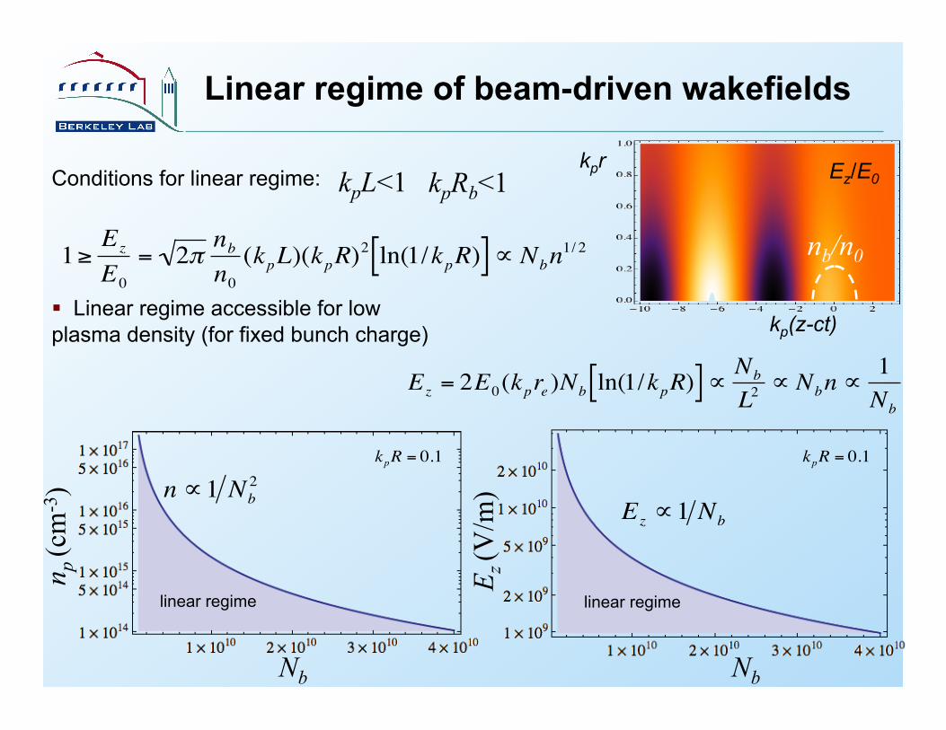
Linear regime of beam-driven wakefields
Conditions for linear regime: kpL<1 kpRb<1 kpr
kp(z-ct)
Ez/E0
€
1≥Ez
E0= 2π nb
n0(kpL)(kpR)
2 ln(1/kpR)[ ]∝ Nbn1/ 2
Linear regime accessible for low plasma density (for fixed bunch charge)
€
Ez = 2E0(kpre )Nb ln(1/kpR)[ ]∝ Nb
L2∝ Nbn ∝
1Nb
Nb Nb
n p (c
m-3
)
E z (V
/m)
€
n ∝1 Nb2
€
Ez ∝1 Nb€
kpR = 0.1
€
kpR = 0.1
linear regime linear regime
nb/n0

PWFA: Energy gain and transformer ratio
15
Energy gain in beam-driven plasma wave given by transformer ratio: • Drive beam losses energy after distance:
• Energy gain of witness bunch:
General considerations (e.g., symmetric bunches):
€
R = E+ E−
€
Ld ~ γ bmc2 eE−
€
Δγmc 2 ~ eE+Ld ~ R γ bmc2( )
€
R ≤ 2
€
kp (z − ct)
€
E−
€
E+€
nb n0
Higher transformer ratios can be achieved using shaped (asymmetric bunches) • Triangular longitudinal bunch
• Ramped bunch train
• Nonlinear blow-out regime: ramped bunches for high R
Lu et al., PAC (2009)
€
E−
€
E+
€
nb n0
€
kp (z − ct)
€
R ~ LbRb
n0nb
Chen et al., PRL (1986)
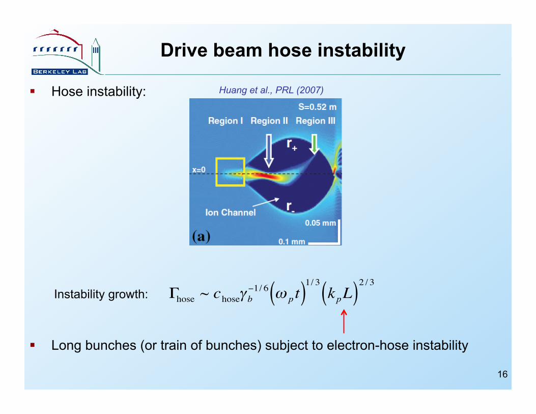
Drive beam hose instability
16
Hose instability:
Long bunches (or train of bunches) subject to electron-hose instability €
Γhose ~ choseγ b−1/ 6 ω pt( )
1/ 3kpL( )
2 / 3
Huang et al., PRL (2007)
Instability growth:

Operational plasma density for laser-driven plasma accelerators
Laser-plasma interaction length limited by laser depletion length:
Excited wake:
Energy gain (single-stage):
Shadwick et al., Phys. Plasmas (2009)
€
Ld = 2.8 1+ a2 /2a2
⎛
⎝ ⎜
⎞
⎠ ⎟
⎡
⎣ ⎢
⎤
⎦ ⎥ λp3
λL2 ∝ n−3 / 2
€
Ez = 0.38 a2
1+ a2 /2
⎛
⎝ ⎜
⎞
⎠ ⎟
⎡
⎣ ⎢
⎤
⎦ ⎥ E0 ∝ n1/ 2
€
Δγmc 2 ~ Ld Ez ∝1 n
plasma density, np (cm-3)
Bea
m e
nerg
y (M
eV)
€
Δγ ∝1n
LBNL 2006
RAL 2009
MPQ 2007
LLNL 2010
LBNL 2004 RAL 2004
LOA 2004
LOA 2006 APRI 2008
U.Mich 2008
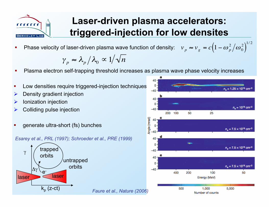
Laser-driven plasma accelerators: triggered-injection for low densites
Phase velocity of laser-driven plasma wave function of density:
Plasma electron self-trapping threshold increases as plasma wave phase velocity increases
€
γ p ≈ λp λ0 ∝1 n
€
vp ≈ vg = c 1−ω p2 ω 0
2( )1/ 2
Low densities require triggered-injection techniques: Density gradient injection Ionization injection Colliding pulse injection
generate ultra-short (fs) bunches
γ
kp (z-ct)
laser"Δγ
trapped orbits
untrapped orbits
laser"e-
Esarey et al., PRL (1997); Schroeder et al., PRE (1999)
Faure et al., Nature (2006)
Plasma wave excitation Transverse wake structure
Beam-driver driven by space-charge fields: extends plasma skin depth Laser-driver driven by local ponderomotive force: extends laser spot size
Regimes of operation: quasi-linear and non-linear Energy gain: operational plasma density
Driver propagation in plasma Driver diffraction/divergence, self-guiding and head-erosion Plasma wave phase velocity ~ driver propagation velocity
Slippage - taper for laser-driven plasma waves Self-trapping for low phase velocities
Driver-plasma coupling Staging for high-energy physics
19
Outline
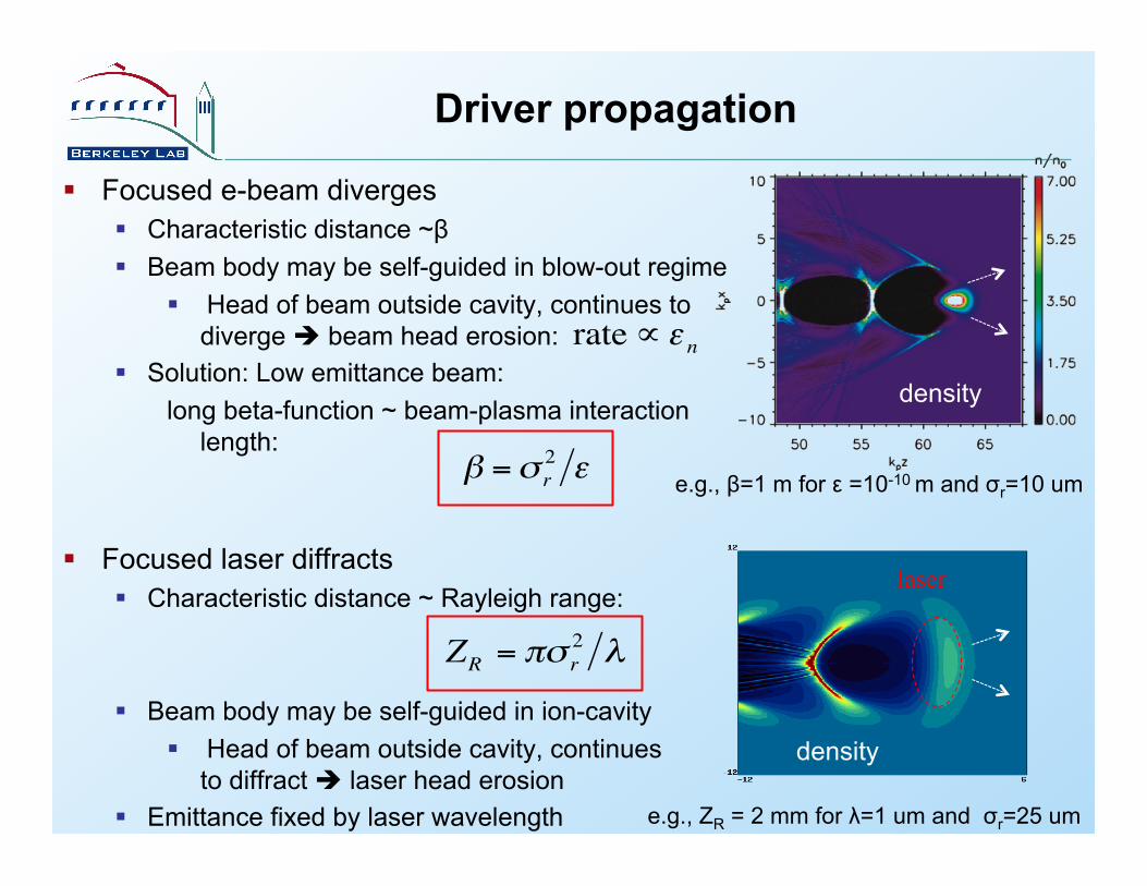
Driver propagation
Focused e-beam diverges Characteristic distance ~β Beam body may be self-guided in blow-out regime
Head of beam outside cavity, continues to diverge beam head erosion:
Solution: Low emittance beam: long beta-function ~ beam-plasma interaction
length:
density
€
β =σ r2 ε e.g., β=1 m for ε =10-10 m and σr=10 um €
rate∝ε n
Focused laser diffracts Characteristic distance ~ Rayleigh range:
Beam body may be self-guided in ion-cavity Head of beam outside cavity, continues
to diffract laser head erosion Emittance fixed by laser wavelength €
ZR = πσ r2 λ
laser
density
e.g., ZR = 2 mm for λ=1 um and σr=25 um
€

Laser diffraction controlled by plasma channel
21
RZ
ZR"
r"
Plasma density, n(r)"
€
dηdr
=ddr1−
ω p2
2ωL2
⎛
⎝ ⎜
⎞
⎠ ⎟ < 0Guiding: "
Laser diffraction: (L ~ZR) Solution: tailor plasma profile to form
plasma channel
Durfee & Milchberg PRL (1993) Geddes et al., PRL (2005)
electrode
gas in
0V+V
bellows
sapphire
channel
laser
in
electrode
gas in
0V+V
bellows
sapphire
channel
laser
in
gas in
0V+V
bellows
sapphire
channel
laser
in
Capillary discharge plasma waveguides: Plasma fully ionized for t > 50 ns After t ~ 80 ns plasma is in quasi-
equilibrium: Ohmic heating is balanced by conduction of heat to wall
Ablation rate small ne ~ 1017 - 1019 cm-3
Hooker et al.

Experimental demonstration: 1 GeV beam using Laser Plasma Accelerator
H-discharge capillary technology: plasma channel production (~1018 cm-3)
22 Leemans et al., Nature Physics (2006); Nakamura et al., Phys. Plasmas (2007)
3cm
1012 MeV 2.9% 1.7 mrad
1.5 J 46 fs 3x1018 cm-3
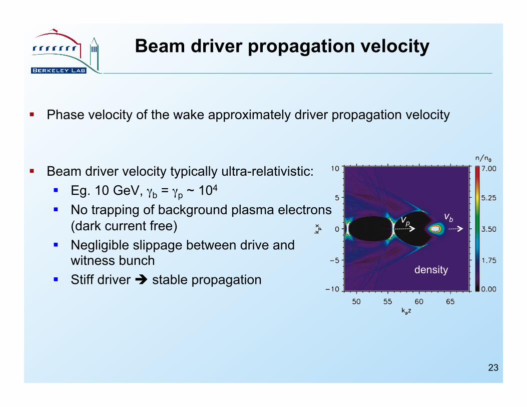
Beam driver propagation velocity
density
vp vb
Phase velocity of the wake approximately driver propagation velocity
Beam driver velocity typically ultra-relativistic: Eg. 10 GeV, γb = γp ~ 104 No trapping of background plasma electrons
(dark current free) Negligible slippage between drive and
witness bunch Stiff driver stable propagation
23
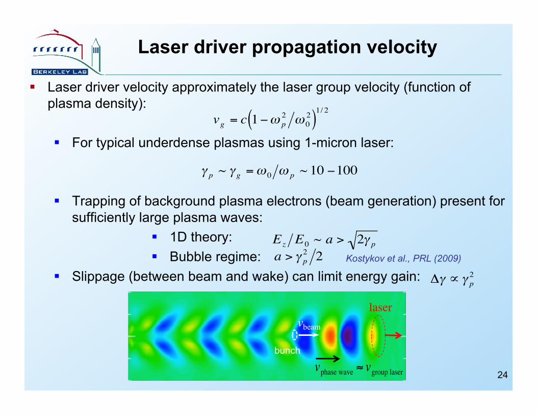
Laser driver propagation velocity
Laser driver velocity approximately the laser group velocity (function of plasma density):
For typical underdense plasmas using 1-micron laser:
Trapping of background plasma electrons (beam generation) present for sufficiently large plasma waves:
1D theory: Bubble regime:
Slippage (between beam and wake) can limit energy gain:
€
vg = c 1−ω p2 ω 0
2( )1/ 2
€
γ p ~ γ g =ω 0 ω p ~ 10 −100
€
Ez E0 ~ a > 2γ p
bunch
€
vphase wave ≈ vgroup laser
vbeam laser
€
Δγ ∝ γ p2
24
€
a > γ p2 2 Kostykov et al., PRL (2009)
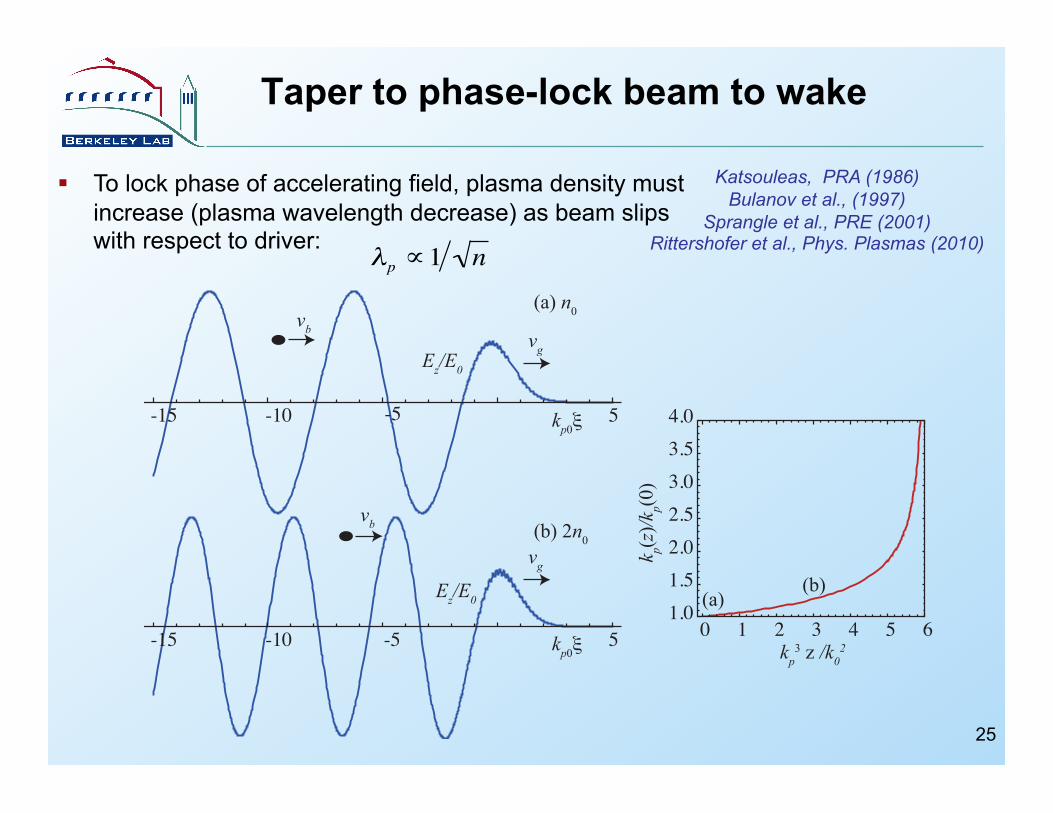
Taper to phase-lock beam to wake
Katsouleas, PRA (1986) Bulanov et al., (1997)
Sprangle et al., PRE (2001) Rittershofer et al., Phys. Plasmas (2010)
-15 -10 5
-15 -10 -5 5
vb
vb
vg
vg
(a) n0
(b) 2n0
kp0!
kp0!
-5
Ez/E0
Ez/E00 1 2 3 4 5 61.0
1.52.02.53.03.54.0
k p(z
)/kp(0
)kp3 z /k02
(a)(b)
€
λp ∝1 n
To lock phase of accelerating field, plasma density must increase (plasma wavelength decrease) as beam slips with respect to driver:
25

Tapering yields enhanced energy gain and efficiency in weakly-relativistic regime
€
n(z)n(0)
€
Nbucket =1
€
Nbucket = 2
€
z Ld€
Δγ€
Nbucket = 2
€
n =1018cm−3
no taper
linear taper
optimal taper
In weakly-relativistic regime: dephasing length << depletion length:
Significant energy gains can be realized with plasma tapering:
Optimal longitudinal density profile: Energy gain:
€
kp3z /k0
2
€
a2 <<1
€
Ldephase ~λp3
λ02 << Ldeplete ~
λp3
a2λ02
Rittershofer et al., Phys. Plasmas (2010)
In plasma channel, focusing and accelerating wakes have different phase velocities: varying density and channel radius to phase lock both.
26
Plasma wave excitation Transverse wake structure
Beam-driver driven by space-charge fields: extends plasma skin depth Laser-driver driven by local ponderomotive force: extends laser spot size
Regimes of operation: quasi-linear and non-linear Energy gain: operational plasma density
Driver propagation in plasma Driver diffraction/divergence, self-guiding and head-erosion Plasma wave phase velocity ~ driver propagation velocity
Slippage - taper for laser-driven plasma waves Self-trapping for low phase velocities
Driver-plasma coupling Staging for high-energy physics
27
Outline
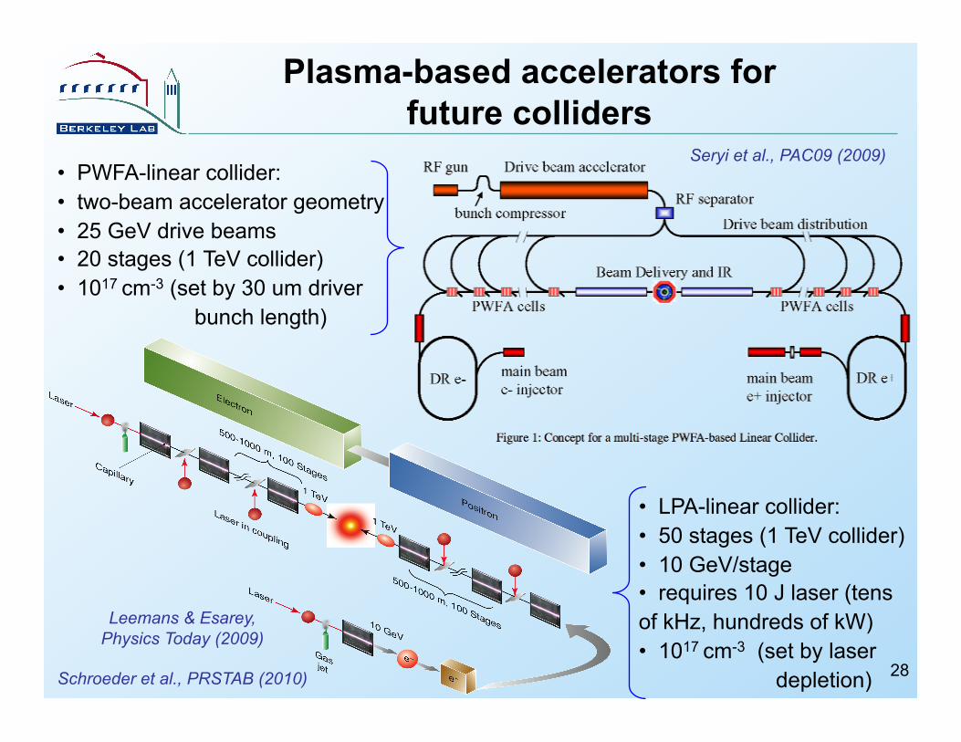
Plasma-based accelerators for future colliders
28
• PWFA-linear collider: • two-beam accelerator geometry • 25 GeV drive beams • 20 stages (1 TeV collider) • 1017 cm-3 (set by 30 um driver
bunch length)
• LPA-linear collider: • 50 stages (1 TeV collider) • 10 GeV/stage • requires 10 J laser (tens of kHz, hundreds of kW) • 1017 cm-3 (set by laser
depletion)
Seryi et al., PAC09 (2009)
Leemans & Esarey, Physics Today (2009)
Schroeder et al., PRSTAB (2010)
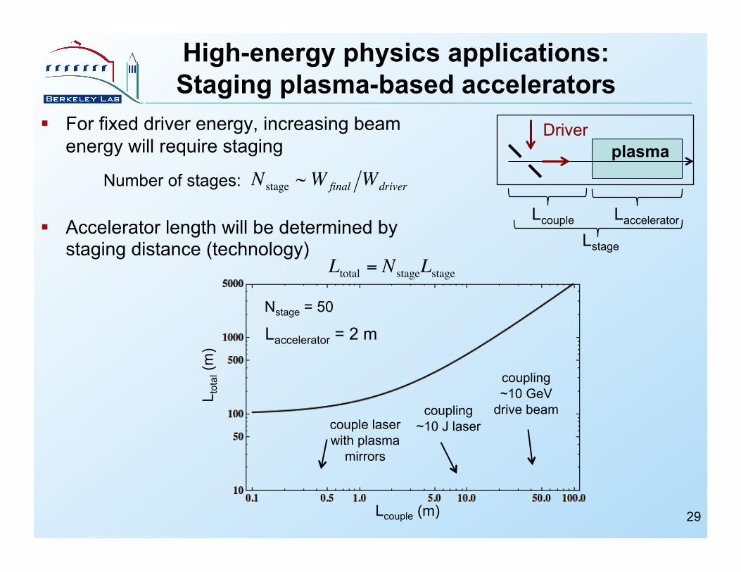
High-energy physics applications: Staging plasma-based accelerators
For fixed driver energy, increasing beam energy will require staging
Accelerator length will be determined by staging distance (technology) Lstage
plasma Driver
Laccelerator Lcouple
€
Nstage ~Wfinal WdriverNumber of stages:
€
Ltotal = NstageLstage
L tot
al (m
)
Lcouple (m)
Nstage = 50
coupling ~10 GeV
drive beam coupling ~10 J laser couple laser
with plasma mirrors
Laccelerator = 2 m
29
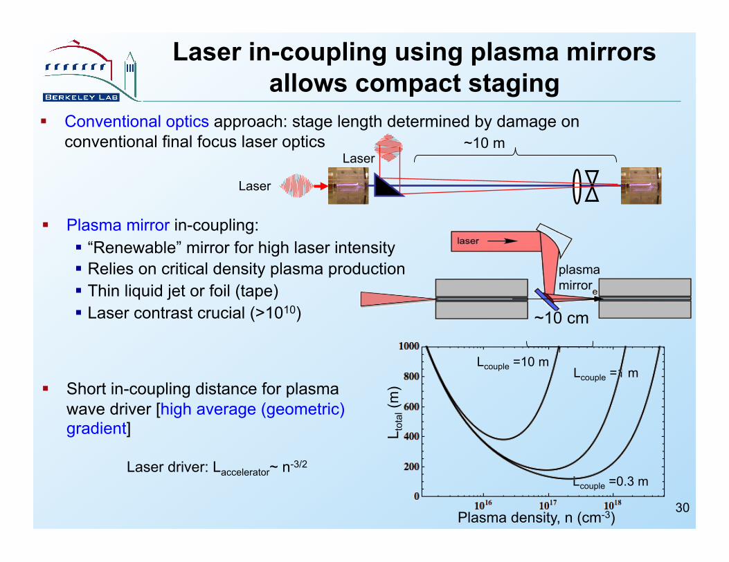
Laser in-coupling using plasma mirrors allows compact staging
Conventional optics approach: stage length determined by damage on conventional final focus laser optics
Laser
Laser ~10 m
30
Plasma mirror in-coupling: “Renewable” mirror for high laser intensity Relies on critical density plasma production Thin liquid jet or foil (tape) Laser contrast crucial (>1010) ~10 cm
plasma mirror
Plasma density, n (cm-3)
Lcouple =0.3 m
Lcouple =1 m Lcouple =10 m
L tot
al (m
) Short in-coupling distance for plasma wave driver [high average (geometric) gradient]
Laser driver: Laccelerator~ n-3/2
Summary
31
Laser or beams use different excitation mechanisms Transverse field structure Access to linear/non-linear regimes Wake phase velocity
Driver propagation: Driver divergence Driver-plasma interaction length and coupling length
Driver technology: High power, high efficiency, high rep rate beam-drivers available. High average laser drivers under development Laser footprint small: <10mx10m for 10’s J delivering 1-10GeV beams Beam-driver footprint potentially small: e.g., use X-band technology with
high transformer ratio (asymmetric bunch)
Many of these physics issues will be addressed at existing and future facilities: