Embed Size (px)
Citation preview

Physikalisch- Technische
Bundesanstalt
Guideline DKD-R 6-1
Calibration of Pressure Gauges
Edition 03/2014
Calibration of Pressure Gauges
DKD-R 6-1
Version: 03/2014
Revision: 2
Page: 2 of 51
Published by the German Calibration Service (DKD) under the patronage of the Physikalisch-Technische Bundesanstalt (PTB) and as a result of the cooperation of PTB and the accredited calibration laboratories together with the Technical Committee “Pressure and Vacuum“. Copyright © 2014 by DKD This work and all parts contained therein are protected by copyright. Any use outside the narrow limits of copyright law is not permitted without consent and liable to prosecution. Deutscher Kalibrierdienst (DKD) Since its foundation in 1977, the DKD brought together calibration laboratories of industrial enterprises, research institutes, technical authorities, inspection and testing institutes. On 3 May 2011, the DKD was reestablished as a technical body of the PTB and the accredited laboratories. This body is called Deutscher Kalibrierdienst (German Calibration Service – DKD) and is under the direction of the PTB. The guidelines and guides elaborated by the DKD represent the state of the art in the respective technical areas of expertise and can be used by the Deutsche Akkreditierungsstelle GmbH (the German accreditation body – DAkkS) for the accreditation of calibration laboratories. The accredited calibration laboratories are now accredited and monitored by the DAkkS as legal successor of the DKD. They carry out calibrations of measuring devices and measuring standards for the measured values and measuring ranges defined during accreditation. The calibration certificates issued by these laboratories prove the traceability to national standards as required by the family of standards DIN EN ISO 9000 and DIN EN ISO/IEC 1702. Calibrations by accredited laboratories provide the user with the security of reliable measuring results, increase the confidence of customers, enhance competitiveness in the national and international markets, and serve as metrological basis for the monitoring of measuring and test equipment within the framework of quality assurance measures. Publications: see the Internet Contact: Physikalisch-Technische Bundesanstalt (PTB) DKD Executive Office Bundesallee 100 D-38116 Braunschweig Telephone: +49 531 592-8021 Internet: www.dkd.eu

Calibration of Pressure Gauges
DKD-R 6-1
Version: 03/2014
Revision: 2
Page: 3 of 51
Table of Contents Page
Foreword ............................................................................................................................. 5
1. Purpose and scope of application ............................................................................... 6
2. Symbols and designations .......................................................................................... 6
2.1 Variables ..................................................................................................................... 6
2.2 Indices ........................................................................................................................ 7
3. Reference and working standards ............................................................................... 8
4. Calibration item ........................................................................................................... 9
5. Calibration capability ................................................................................................. 10
6. Ambient conditions .................................................................................................... 10
7. Calibration method .................................................................................................... 11
8. Measurement uncertainty .......................................................................................... 14
8.1 Definition [VIM 2.26] .................................................................................................. 14
8.2 Procedure ................................................................................................................. 14
8.2.1 Model of measurement [VIM 2.48] ............................................................................ 14
8.2.2 Sum/difference model ............................................................................................... 15
8.2.3 Product/quotient model ............................................................................................. 15
8.2.4 Input/influence quantities .......................................................................................... 16
8.2.5 Potential influence quantities, example ..................................................................... 18
8.3 Calibration of Boudon tube pressure gauges ............................................................ 19
8.3.1 Model of measurement ............................................................................................. 19
8.3.2 Uncertainty budget .................................................................................................... 21
8.3.3 Load step-related uncertainty budget ........................................................................ 22
8.3.4 Single-figure indication .............................................................................................. 22
8.4 Calibration of electrical pressure gauges................................................................... 23
8.5 Calibration of pressure transducers and pressure transmitters with electrical output 24
8.5.1 Model of measurement ............................................................................................. 24
8.5.2 Uncertainty budget .................................................................................................... 26
8.5.3 Load step-related uncertainty budget ........................................................................ 27
8.5.4 Single-figure indication .............................................................................................. 27
8.6 Relevant influence quantities of the calibration item for the uncertainty budget ......... 28
8.6.1 Resolution r ............................................................................................................... 28
8.6.1.1 Analogue indicating devices ...................................................................................... 28
8.6.1.2 Digital indicating devices ........................................................................................... 28
8.6.1.3 Fluctuation of readings .............................................................................................. 28
8.6.2 Zero deviation f0 ....................................................................................................... 28
8.6.3 Repeatability b' ......................................................................................................... 29
8.6.4 Reproducibility b ....................................................................................................... 29

Calibration of Pressure Gauges
DKD-R 6-1
Version: 03/2014
Revision: 2
Page: 4 of 51
8.6.5 Hysteresis h .............................................................................................................. 29
9. Evaluation of measurement results and statements in the calibration certificate ....... 30
9.1 Determination of other parameters ............................................................................ 31
9.1.1 Mean values ......................................................................................................... 31
9.1.2 Error span U‘ ............................................................................................................. 31
9.1.3 Conformity ................................................................................................................ 31
9.2 Visualisation of the calibration result ......................................................................... 31
9.2.1 Bourdon tube pressure gauges, electrical pressure gauges: ..................................... 31
9.2.2 Pressure transmitters with electrical output ............................................................... 33
9.3 Limiting values for uncertainty statements ................................................................. 35
10. Additional rules and standards .................................................................................. 36
Annex A Estimate of the measurement uncertainty to be attributed to the values of the pressure balance under conditions of use .......................................................... 39
Annex B Example: Uncertainty budget for the calibration of a Bourdon tube pressure gauge ................................................................................................................. 41
Annex C Example: Uncertainty budget for the calibration of a digital electrical pressure gauge ................................................................................................................. 43
Annex D Example: Uncertainty budget for the calibration of a pressure transmitter with electrical output .................................................................................................. 45
Annex E (Informative) Measurement uncertainties of reference and working standards ... 50
Annex F Recalibration intervals (recommendation) .......................................................... 51
x
Calibration of Pressure Gauges
DKD-R 6-1
Version: 03/2014
Revision: 2
Page: 5 of 51
Foreword
DKD guidelines are application documents regarding the DIN EN ISO/IEC 17025 requirements. The guidelines contain a description of the technical, process-related and organizational procedures which accredited calibration laboratories use as a model for defining internal processes and regulations. DKD guidelines may become an essential component of the quality management manuals of calibration laboratories. By implementing the guidelines, it is ensured that the devices to be calibrated are all treated equally in the various calibration laboratories and that the continuity and comparability of the work of the calibration laboratories are improved. The DKD guidelines should not impede the further development of calibration procedures and processes. Deviations from guidelines as well as new procedures are allowed in agreement with the accreditation body if there are technical reasons to support this action. The present guideline was created by the Technical Committee “Pressure and Vacuum“, in cooperation with the PTB and the accredited calibration laboratories. The guideline has been approved by the Board of the DKD. To make things clearer and to ensure a better understanding, revision 2 contains minor corrections in the examples as well as editorial changes.
Calibration of Pressure Gauges
DKD-R 6-1
Version: 03/2014
Revision: 2
Page: 6 of 51
1. Purpose and scope of application This guideline serves to establish minimum requirements for the calibration procedure and the estimation of the measurement uncertainty in the calibration of pressure gauges. It applies to Bourdon tube pressure gauges, electrical pressure gauges and pressure transmitters with electrical output for absolute pressure, differential pressure and excess pressure with negative and positive values.
2. Symbols and designations
The symbols are subject-related which means that, as a rule, they are listed in the order in which they appear in the text.
2.1 Variables
M1 ... M6 Measurement series
EW Highest value (of the calibration range)
Y Output quantity of the model of measurement [VIM 2.51] X Input quantity of the model of measurement [VIM 2.50]
X Influence quantity [VIM 2.52] K Correction factor
x Best estimate of the input quantity y Best estimate of the output quantity
c Sensitivity coefficient k Expansion factor [VIM 2.38] a Half-width of a distribution
Probability
Expected value
u Standard uncertainty [VIM 2.30] U Expanded uncertainty [VIM 2.35] w Relative standard uncertainty [VIM 2.32] W Relative expanded uncertainty
p Pressure
Systematic measurement deviation of the quantity of pressure
p Influence quantity in the dimension of pressure
S Transmission coefficient (of the pressure transducer)
Systematic deviation of the transmission coefficient from the single-figure
indication
U…. Voltage with different indices (Sections 8.5.1 and 8.5.2)
G Amplification factor
r Resolution f0 Zero deviation b' Repeatability [VIM 2.21] b Reproducibility [VIM 2.23] h Hysteresis
)( iX ig
...E
p
S

Calibration of Pressure Gauges
DKD-R 6-1
Version: 03/2014
Revision: 2
Page: 7 of 51
U‘ Error span W‘ Relative error span
S' Slope of a linear regression function
pe Excess pressure m Mass of the load masses g Acceleration due to gravity
Density A Effective cross section of the piston-cylinder system
Deformation coefficient of the piston-cylinder system
Linear thermal expansion coefficient of the piston
Linear thermal expansion coefficient of the cylinder t Temperature of the piston-cylinder system
h Height difference between the reference planes
2.2 Indices
Sp Supply voltage j Number of the measurement point m Number of the measurement series n Number of measurement cycles
a Air
Fl Pressure-transmitting medium
m Load mass
0 Standard conditions t = 20 °C
Std Standard conditions
appl Conditions of use
corr Correction (of the measurement value)
Calibration of Pressure Gauges
DKD-R 6-1
Version: 03/2014
Revision: 2
Page: 8 of 51
3. Reference and working standards
The calibration is carried out by direct comparison of the measurement values of the calibration item with those of the reference or working standard which has been directly or indirectly traced back to a national standard.
The reference standards used are pressure gauges of long-time stability as, for example, pressure balances and liquid-level manometers, or less long-term stable electrical pressure gauges (see Annex F, p.49). They are calibrated at regular intervals and provided with a calibration certificate stating the expanded measurement uncertainty under standard conditions (among other things, standard or local acceleration due to gravity, 20°C, 1 bar). The reference standard is subject to surveillance and documentation by the accreditation body. If the calibration does not take place under standard conditions, corrections are to be applied to the pressure calculation. The measurement uncertainties to be attributed to these corrections due to influence quantities are to be taken into account as further contributions in the uncertainty budget1.
When calculating the measurement uncertainty of the standards used, all relevant influence quantities are to be taken into account. In case of indicating pressure gauges that are used as standards, the resolution has to be considered a second time when calculating the measurement uncertainty.
The working standards documented in the quality manual of the laboratory are calibrated in an accredited laboratory and provided with a calibration certificate stating the expanded uncertainty at the time of calibration. The working standard is subject to surveillance by the accreditation body. Depending on their type, the working standards may vary considerably.
Recommendation: The measurement uncertainty attributed to the measurement values of the reference or working standard should not exceed 1/3 of the aspired uncertainty
2 which will presumably be attributed to the measurement values of the
calibration item.
1 The term uncertainty budget continues to be accepted.
2 The measurement uncertainty aimed at is the uncertainty which can be achieved when specified calibration efforts are
made (uncertainty of the values of the standard, number of measurement series, etc.). It may be equal to or greater than the best measurement capability.

Calibration of Pressure Gauges
DKD-R 6-1
Version: 03/2014
Revision: 2
Page: 9 of 51
4. Calibration item
The calibration items are pressure gauges of the three types represented in Figure 1.
Figure 1: Types of pressure gauges
For the calibration of pressure transmitters with electrical output (3) auxiliary measuring devices of the accredited laboratory have to be used – as opposed to electrical pressure gauges (2) which only require the provision of a voltage or current source. These auxiliary devices serve to convert the electrical signal into a readable indication. The measurement uncertainty attributed to the measurement values of the auxiliary measuring devices is to be taken into account in the uncertainty budget. To ensure traceability, the auxiliary measuring devices must have been calibrated and a statement on the measurement uncertainty to be attributed to the measurement values must be available.
When choosing the auxiliary measuring devices, it must be ensured that their uncertainty contributions do not significantly affect the aspired measurement uncertainty of the calibration item.
Type Standard Calibration
item Auxiliary
measuring devices
(1)
(2) Electrical pressure gauge
(3) Pressure transmitter with electrical output
Bourdon tube pressure gauge
Reference or working standard
p
U , I , f
Reference or working standard
Voltage source
Indication p
Auxiliary power
Indication
p
U , I , f
Reference or working standard
Bourdon tube pressure gauge gauge
Calibration of Pressure Gauges
DKD-R 6-1
Version: 03/2014
Revision: 2
Page: 10 of 51
In the case of calibration items with a digital interface (e.g. RS232, RS485 IEEE488, etc.), this interface can be used instead of the display. It has to be ensured that the data that are read out are unequivocally interpreted and processed.
5. Calibration capability
The handling of a calibration order requires the calibration capability (suitability) of the calibration item, i.e. the current status of the calibration item should meet the generally recognized rules of technology as well as the specifications according to the manufacturer's instructions. The calibration capability has to be ascertained by means of external inspections and functional tests. External inspections cover, for example:
- visual inspection for damage (pointer, threads, sealing surface, pressure channel)
- contamination and cleanness
- visual inspections regarding labelling, readability of indications
- test whether the required documents for the calibration (technical data, operating instructions) are available
Functional tests cover, for example:
- leak tightness of the calibration item’s line system
- electrical operability
- proper function of the control elements (e.g. zero adjustability)
- adjusting elements in defined position
- error-free execution of self-test and/or self-adjustment functions; if necessary, internal reference values are to be read out via the EDP interface
- torque dependence (zero signal) during mounting
Note: If repair work or adjustments are required to ensure the calibration capability, this work has to be agreed upon between customer and calibration laboratory. Relevant device parameters are to be documented, as far as possible, before and after the adjustments.
6. Ambient conditions
The calibration is to be carried out after a temperature equalisation between calibration item and environment within the permissible temperature range (18 °C to 28 °C). A warm-up time of the calibration item or a possible warming of the calibration item by the supply voltage must be considered. The warm-up period depends on personal experience or specifications provided by the manufacturer.
The calibration is to be carried out at a steady ambient temperature. The recommended
temperature variation during calibration is limited to 1 K. It might be necessary to consider an additional uncertainty contribution when exploiting the maximum tolerance limits; this temperature must lie between 18 °C and 28 °C and has to be recorded.
Note: When using piston pressure gauges (pressure balances), the air density may have a significant impact on the calibration result (air buoyancy mass and hydrostatic pressure); therefore, apart from the ambient temperature, also the atmospheric pressure and the relative humidity must be recorded and taken into account. This information must be stated in the calibration certificate (see DAkkS-DKD 5).
Calibration of Pressure Gauges
DKD-R 6-1
Version: 03/2014
Revision: 2
Page: 11 of 51
7. Calibration method
- The pressure gauge is to be calibrated as a whole (measuring chain), if possible.
- The required mounting position is to be considered.
- The calibration is to be carried out at equally distributed measurement points across the calibration range.
- Depending on the desired measurement uncertainty, one or more measurement series are necessary (see Table 1 or Figure 2, respectively).
- If the calibration item’s behaviour regarding the influence of the torque is not sufficiently known during mounting, the reproducibility must be determined by an additional clamping. In this case, the value of the torque is to be documented.
- The difference in altitude between the reference altitudes of the standard and the calibration item is to be minimized or the correction is to be calculated.
Upon request, further influence quantities (e.g. temperature influence from further measurement series at different temperatures) can be determined.
The comparison of the measured value between calibration item and reference or working standard is feasible in two ways:
- adjustment of the pressure according to the indication of the calibration item
- adjustment of the pressure according to the indication of the standard
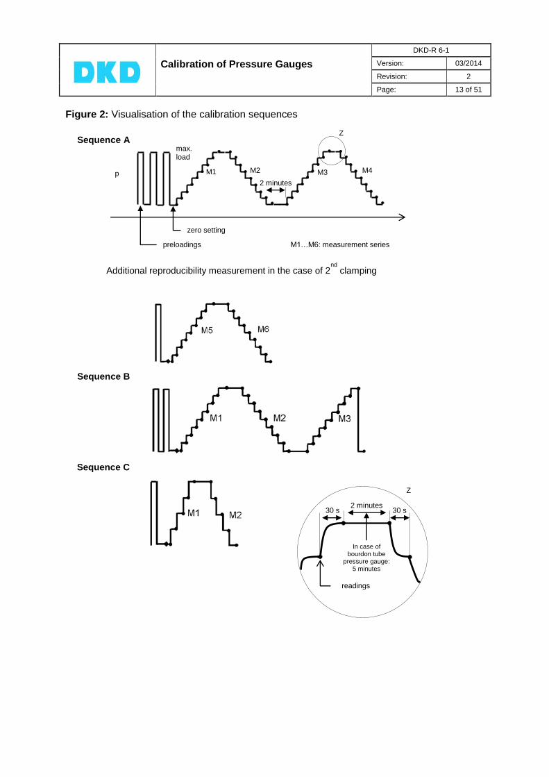
The preloading time at the highest value and the time between two preloadings should at least be 30 seconds. After preloading and after steady conditions have been reached, the indication of the calibration item is set to zero - provided that this is supported by the calibration item. The zero reading is carried out immediately afterwards. As to the pressure step variation of a measurement series, the time between two successive load steps should be the same and not shorter than 30 seconds, and the reading should be performed no earlier than 30 seconds after the start of the pressure change. Especially Bourdon tube pressure gauges have to be slightly tapped to minimize any frictional effect of the pointer system. The measured value for the upper limit of the calibration range is to be registered before and after the waiting time. The zero reading at the end of a measurement series is carried out at the earliest 30 seconds after the complete relief.
The calibration effort in dependence on the desired measurement uncertainty (cf. Note 2, Section 3) is illustrated in Figure 2 which shows the sequence of the calibration:

Calibration of Pressure Gauges
DKD-R 6-1
Version: 03/2014
Revision: 2
Page: 12 of 51
Table 1: Calibration sequences
Sequence Desired measure-
ment uncertainty
in %
of the measure-
ment span
Minimum number of measure-
ment points
Number
of pre-loadings
Load change +
waiting time
Waiting time at upper limit
of the measure-
ment range
Number of measurement
series
(*) with zero point
up/down
(**)
seconds
(***)
minutes
up
down
A < 0.1 9 3 > 30 2 2 2
B 0.1 ... 0,6 9 2 > 30 2 2 1
C > 0.6 5 1 > 30 2 1 1
(*) The reference to the measurement span was chosen in order to allow the selection of
the sequence (necessary calibration effort) from the table, since the accuracy specifications provided by the manufacturers are usually related to the measurement span. In case of measuring devices for which specifications of the measurement value or assembled specifications are stated, Table 1 is to be applied, using the specification limit (e.g. of the measurement span).
(**) In any case, one has to wait until steady state conditions (sufficiently stable indication of
the standard and the calibration item) are reached. (***) For Bourdon tube pressure gauges, a waiting time of 5 minutes is to be observed. The
waiting times can be reduced for quasi-static calibrations (piezoelectric sensor principle).
Note: The calibration of items with a measurement range greater than 2500 bar basically requires the application of calibration sequence A. If clamping effects are observed, the calibration is to be repeated with a second clamping. Calibration items that are calibrated with positive and negative gauge pressure should at least be calibrated at two points in the negative range (e.g. at -1 bar and -0.5 bar); the remaining measurement points should be calibrated in the positive range. If several references are required to carry out a calibration, the pressure at the calibration item must be kept constant when changing the reference. If this is not practicable (e.g. change of the mounting position, second clamping), a complete new calibration sequence has to be carried out.
Calibration of Pressure Gauges
DKD-R 6-1
Version: 03/2014
Revision: 2
Page: 13 of 51
Figure 2: Visualisation of the calibration sequences
Sequence B
Sequence C
30 s 30 s 2 minutes
readings
In case of bourdon tube
pressure gauge: 5 minutes
Z
Sequence A
p
max. load
M1 M2
2 minutes M3 M4
zero setting
preloadings M1…M6: measurement series
Additional reproducibility measurement in the case of 2nd
clamping
Z

Calibration of Pressure Gauges
DKD-R 6-1
Version: 03/2014
Revision: 2
Page: 14 of 51
8. Measurement uncertainty
8.1 Definition [VIM 2.26]
The measurement uncertainty is a non-negative parameter characterizing the dispersion of the values being attributed to the measurand, based on the information used.
8.2 Pocedure
8.2.1 Model of measurement [VIM 2.48]
The determination of the measurement uncertainty is generally carried out according to the procedure described in the document DAkkS-DKD-3[18]. This document uses the following terms and calculation rules on condition that no correlations between the input quantities are to be allowed for:
Model function
Standard uncertainty
Standard uncertainty attributed to the input/influence quantity
Sensitivity coefficient
Contribution to the standard uncertainty attributed to the output quantity due to the standard
uncertainty of the input
quantity
Standard uncertainty attributed to the output quantity
Expanded uncertainty Expanded uncertainty
Coverage factor for a measurand of largely normal
distribution and a coverage probability of approximately 95%
If relative measurement uncertainties are used, the variables u, U are replaced by the variables w, W.
With complex models, the calculation rule rapidly leads to an analytical determination of the sensitivity coefficients which is no longer manageable. As a result, there will be a shift toward a software-based numerical determination of the sensitivity coefficients.
),...,,( 21 Nxxxfy
iu x
ic
i
i
fc
x
iu y
iu x
ix
i i iu y c u x
u y
N
i
i
N
i
i
yuyu
yuyu
1
2
1
22
U y U y k u y
k 2k

Calibration of Pressure Gauges
DKD-R 6-1
Version: 03/2014
Revision: 2
Page: 15 of 51
Besides this general calculation rule, there are two particular rules which lead to sensitivity coefficients ci = ± 1 and thus to the simple quadratic addition of the uncertainties of the input/influence quantities. This enables the simple determination of the measurement uncertainty without software support.
Note: Also the “simple“ model must of course correctly reflect the physical process of measurement/calibration. If necessary, more complex relations have to be represented by means of a suitable model (no special case) in a separate uncertainty budget (see Annex A: Estimate of the measurement uncertainty to be attributed to the values of the pressure balance under conditions of use).
8.2.2 Sum/difference model
(1)
Y Output quantity X Input quantity (quantities)
Influence quantity (quantities) Expected value [the components do not contribute to the
calculation of the output quantity (corrections are not applied) but they make a contribution to the measurement uncertainty]
e.g. model for determining the measurement deviation of the indication:
(2)
This model is particularly suitable for calibration items with an indication of their own in units of pressure (e.g. Bourdon tube pressure gauge, electrical pressure gauge). Here, the measurement uncertainties are also stated in the unit of the physical quantity of pressure (pascal, bar, etc.).
8.2.3 Product/quotient model
(3)
Y Output quantity X Input quantity (quantities)
Correction factor(s) Influence quantity (quantities)
1
δN
i
i
Y X X
1
N
i
i
Y X K
i
ii
X
XK
δ1
δ iX
δ 0iE X
δ iX

Calibration of Pressure Gauges
DKD-R 6-1
Version: 03/2014
Revision: 2
Page: 16 of 51
; Expected values [the components do not contribute to the
calculation of the output quantity (corrections are not applied) but they make a contribution to the measurement uncertainty]
e.g. model for determining the transmission coefficient of a pressure transducer (strain-gauge transducer):
(4)
This model is particularly suitable for calibration items without an indication of their own (e.g. pressure transmitters with electrical output) using relative measurement uncertainties (w) of the dimension 1 (dimensionless or %).
8.2.4 Input/influence quantities
The measurement uncertainties attributed to the input/influence quantities are subdivided into two categories as regards their determination:
Type A: For the determination of the value and its attributed standard uncertainty, analysis methods from statistics for measurement series under repeatability conditions
(n 10) are applied.
Type B: The determination of the value and its attributed standard uncertainty is based on other scientific findings and can be estimated from the following information:
data from previous measurements
general knowledge and experience regarding the characteristics and the behaviour of measuring instruments and materials
manufacturer’s specifications
calibration certificates or other certificates
reference data from manuals
In many cases, only the upper and lower limits (a+ and a-) can be stated for the
value of a quantity, whereby all values within the bounds can be considered equally probable. This situation can best be described by a rectangular probability density.
With (5)
the estimate of the input/influence quantity
(6)
and the attributed standard uncertainty
(7)
are obtained.
2a a a
1
2ix a a
3
i
au x
δ 0iE X 1iE K

Calibration of Pressure Gauges
DKD-R 6-1
Version: 03/2014
Revision: 2
Page: 17 of 51
If the values are more likely to be found in the middle or at the edge of the interval, then it is reasonable to assume a triangular or U-shaped distribution.
Table 2: Other type B distribution shapes
Shape of distribution Standard uncertainty
normal
triangular
U-shaped
etc.
k
Uu
6
au
2
au

Calibration of Pressure Gauges
DKD-R 6-1
Version: 03/2014
Revision: 2
Page: 18 of 51
8.2.5 Potential influence quantities, example
To establish the model of the measurement uncertainty, it is recommended to graphically represent the influence quantities. As an example, the following illustration shows the potential influence quantities for the calibration of a pressure gauge against a pressure balance. Figure 3 shows the block diagram of the pressure gauge type (3) from Section 4, Figure 1.
Figure 3: Influence quantities in the calibration of a pressure gauge
* ENOB … Effective Number of Bits (Characteristic value of A/D converters, which characterizes their actual accuracy and performance better than the resolution)
Note: For a first approach, it is sometimes helpful to subdivide the influence values according to whether they are associated with the
- standard - procedure - calibration item.
The measurement uncertainties which are attributed to the values of the standard, the adapter and the output unit are taken from calibration certificates (generally normally distributed, k = 2). When using electrical pressure gauges, their long-term stability, resolution and temperature dependence are to be assessed as a contribution to the measurement uncertainty and, if necessary, must be taken into account.
Pressure standard
Pressure balance
Sensor
Adapter, output unit
Evaluation
Tube
system
Temperature Air density
Local acceleration due to gravity
Temperature
Density Reference level
Pressure gauge
Measurement uncertainty attributed to the
values of the standard under normal conditions
- separation device - hoses - fittings - valves - pressure-transmitting medium
Reference level
Characteristics of the sensor - zero deviation - repeatability - reproducibility - hysteresis - drift
Temperature Reference level
Power supply Position
Resolution, ENOBs
Interpolation deviations
Conversions
Roundings
Difference of reference levels
Drift
Measurement uncertainty attributed to the adapter, output unit

Calibration of Pressure Gauges
DKD-R 6-1
Version: 03/2014
Revision: 2
Page: 19 of 51
8.3 Calibration of Bourdon tube pressure gauges
8.3.1 Model of measurement
For example, a simple sum/difference model is suitable for determining the measurement deviation of the indication – separately for the measurement values in the direction of increasing pressure and for the measurement values in the direction of decreasing pressure, according to the calibration procedures (see Section 7, Table 1 or Figure 2, respectively):
(8)
Output quantity; deviation of the indication Index ... stands for up/down or mean (see eqs. 8 and 9)
3
Indication of the pressure gauge Index ... stands for up/down or mean (see eqs. 8 and 9)
4 5
Value of the reference standard6
Influence quantity "zero deviation" 7
Influence quantity "repeatability"
and for the mean values from the up and down measurements:
(9)
(10)
Influence quantity "hysteresis" 7 5
3 Output quantity
4 Input quantities
5 Quantities for determining the measurement uncertainty
6 The value of the reference standard takes into account the use of the pressure balance under conditions of use (application
of corrections). Therefore, the uncertainty budget, too, contains uncertainty contributions from the pressure balance both under standard conditions and under conditions of use. The latter contribution is determined in uncertainty budgets (see Annex A: "Estimate of the measurement uncertainty which is to be attributed to the values of the pressure balance under conditions of use") for the influences of the temperature, of the thermal linear expansion coefficient, of the acceleration due to gravity, of the air density, of the deformation coefficient (pressure balance) or for density, acceleration due to gravity, altitude (height difference). 7 Influence quantities
...Y p
Calibration of Pressure Gauges
DKD-R 6-1
Version: 03/2014
Revision: 2
Page: 20 of 51
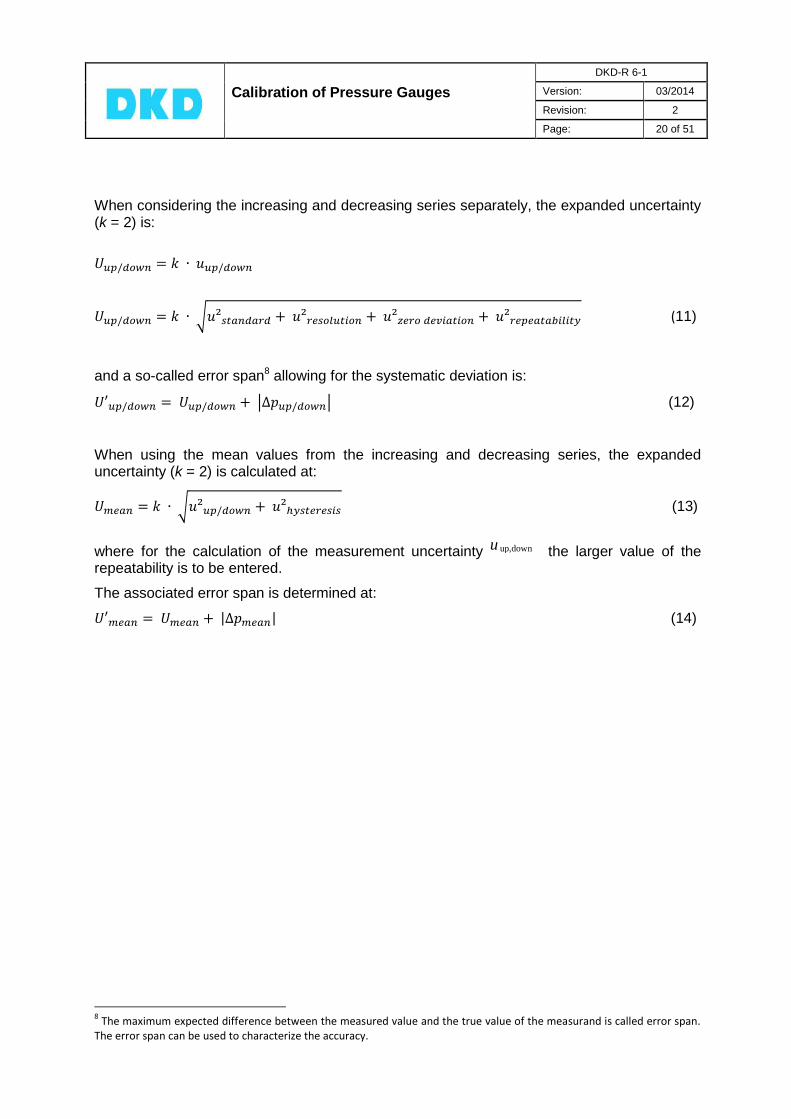
When considering the increasing and decreasing series separately, the expanded uncertainty (k = 2) is:
(11)
and a so-called error span8 allowing for the systematic deviation is:
(12)
When using the mean values from the increasing and decreasing series, the expanded uncertainty (k = 2) is calculated at:
(13)
where for the calculation of the measurement uncertainty the larger value of the repeatability is to be entered.
The associated error span is determined at:
(14)
8 The maximum expected difference between the measured value and the true value of the measurand is called error span.
The error span can be used to characterize the accuracy.
up,down u

Calibration of Pressure Gauges
DKD-R 6-1
Version: 03/2014
Revision: 2
Page: 21 of 51
8.3.2 Uncertainty budget
The knowledge regarding the input/influence quantities is preferably summarized in a table.
Table 3: Uncertainty budget for the calibration of a Bourdon tube pressure gauge
Cont. No.
Quan-tity
Best estimate
Width of the
distribu-tion
Probability distribution
Divisor Standard
uncertainty
Sensiti-vity coef-
ficient
Uncer-tainty contri-bution
Unit
9
1 rectangle 1
bar
2
normal 2
-1
bar
3
0 rectangle
1
bar
4
0 rectangle 1
bar
5
0 rectangle 1
bar
Y bar
9 It is recommended to carry over the unit of the uncertainty contributions
(unit of the physical quantity, unit of indication, etc.).
iX ix 2a )( iX ig iu x ic iu y
2r 3 2
1 2
3 2
ru r
ru
0f 3
2
00
1
3 2
fu f
0fu
b 3 2
1
3 2
bu b
bu
h 3 2
1
3 2
hu h
hu
...p u y
hysteresis δ p
repeatability δ p
zero deviation δ p
standard u standard u , standard i p standard p
, ind,... i p ind,... p

Calibration of Pressure Gauges
DKD-R 6-1
Version: 03/2014
Revision: 2
Page: 22 of 51
8.3.3 Load step-related uncertainty budget
The estimate of the measurement uncertainty has to be carried out for each calibration value, i.e. for each load step. For a greater clarity, the following tabular representation is recommended for increasing, decreasing and mean values:
Table 4: Uncertainty budget
Pressure Measure-
ment deviation
Standard uncertainty u
Expanded uncertainty
U (k=2)
Error span U‘
Contribution
1 ...
Contribution n
bar bar bar bar bar
min.
...
max.
8.3.4 Single-figure indication
In addition to the error span for each load step, the customer can be informed of the maximum error span in the range for which the calibration is valid (in the unit of the pressure related to the measurement value or the measurement span). Similarly, the conformity can be confirmed (see page 31).

Calibration of Pressure Gauges
DKD-R 6-1
Version: 03/2014
Revision: 2
Page: 23 of 51
8.4 Calibration of electrical pressure gauges
The model of the measurement and the measurement uncertainty budget for the calibration of a Bourdon tube pressure gauge can also be used for calibrating an electrical pressure gauge (numerically correct indication in units of pressure). If necessary, a portion of “reproducibility b with repeated mounting“ is to be taken into account.
Influence quantity "reproducibility" 7 5
Table 5: Additional component in determining the measurement uncertainty for the calibration of an electrical pressure gauge
Cont. No.
Quantity Best
estimate
Width of the
distribu-tion
Probability distribution
Divisor Standard
uncertainty
Sensiti-vity coef-
ficient
Uncer-tainty
contribu-tion
Unit
6
0 rectangle 1
bar
The expanded uncertainty (k = 2) for the increasing and decreasing series is determined as follows:
(15)
The determination of the associated error span for the increasing and decreasing series and for the expanded uncertainty and the error span for the mean value is carried out in analogy to the procedure for the Bourdon tube pressure gauge.
iX ix 2a )( iX ig iu x ic iu y
b 3 2
1
3 2
bu b
bu
reproducibility δ p
Calibration of Pressure Gauges
DKD-R 6-1
Version: 03/2014
Revision: 2
Page: 24 of 51
8.5 Calibration of pressure transducers and pressure transmitters with electrical output
8.5.1 Model of measurement
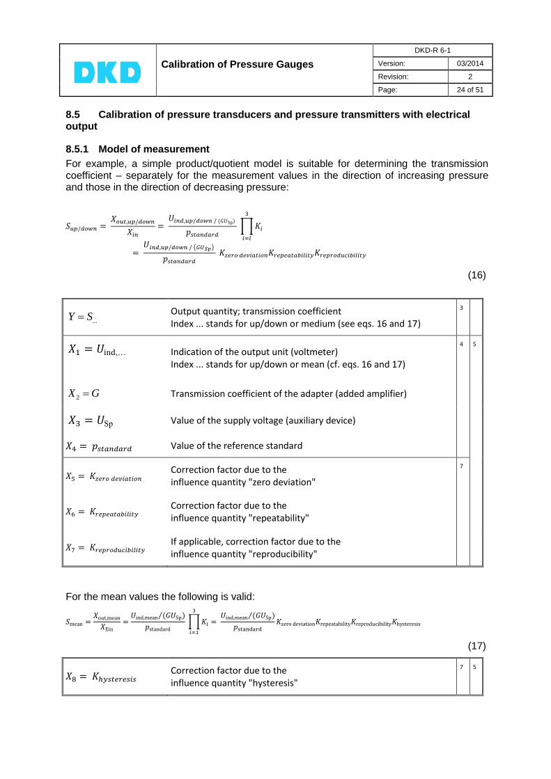
For example, a simple product/quotient model is suitable for determining the transmission coefficient – separately for the measurement values in the direction of increasing pressure and those in the direction of decreasing pressure:
(16)
Output quantity; transmission coefficient Index ... stands for up/down or medium (see eqs. 16 and 17)
3
Indication of the output unit (voltmeter) Index ... stands for up/down or mean (cf. eqs. 16 and 17)
4 5
Transmission coefficient of the adapter (added amplifier)
Value of the supply voltage (auxiliary device)
Value of the reference standard
Correction factor due to the influence quantity "zero deviation"
7
Correction factor due to the influence quantity "repeatability"
If applicable, correction factor due to the influence quantity "reproducibility"
For the mean values the following is valid:
(17)
Correction factor due to the influence quantity "hysteresis"
7 5
...Y S
2X G

Calibration of Pressure Gauges
DKD-R 6-1
Version: 03/2014
Revision: 2
Page: 25 of 51
When the increasing and decreasing series are considered separately, the relative expanded measurement uncertainty (k = 2) is determined at:
(18)
and the associated error spans at:
(19)
with the systematic deviation
(20)
with S' preferably representing the slope of the regression line through all measurement values and through the zero point of the output signal of the pressure transmitter.
When using the mean value from increasing and decreasing series, the relative expanded measurement uncertainty (k = 2) is calculated at:
(21)
where for the calculation of the measurement uncertainty wup/down the larger value of the
repeatability is to be inserted.
The associated error span is determined at:
(22)
with
(23)
(for S', see above)
Calibration of Pressure Gauges
DKD-R 6-1
Version: 03/2014
Revision: 2
Page: 26 of 51
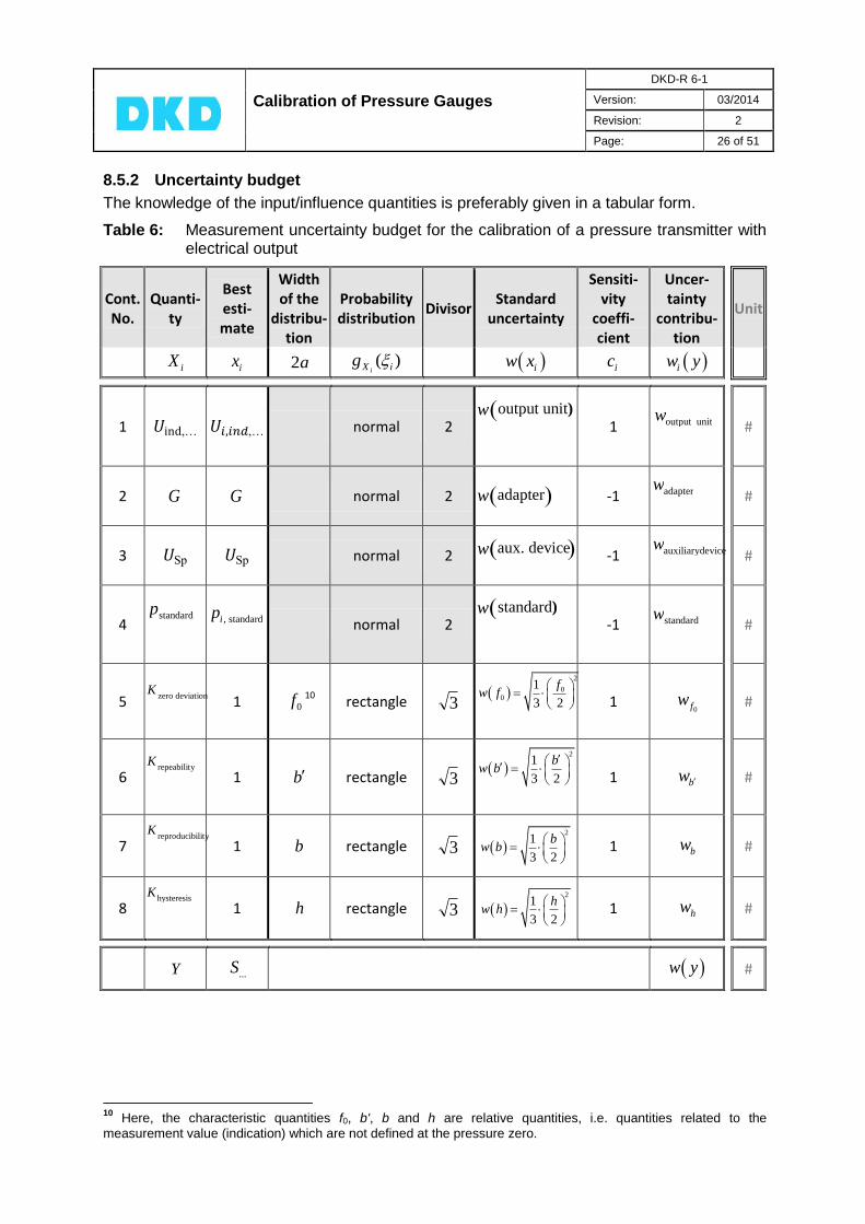
8.5.2 Uncertainty budget
The knowledge of the input/influence quantities is preferably given in a tabular form.
Table 6: Measurement uncertainty budget for the calibration of a pressure transmitter with electrical output
Cont. No.
Quanti-ty
Best esti-mate
Width of the
distribu-tion
Probability distribution
Divisor Standard
uncertainty
Sensiti-vity
coeffi-cient
Uncer-tainty
contribu-tion
Unit
1 normal 2
1
#
2 normal 2
-1
#
3 normal 2
-1
#
4
normal 2
-1
#
5
1 10 rectangle
1
#
6
1 rectangle
1
#
7
1 rectangle 1
#
8
1 rectangle 1
#
Y #
10
Here, the characteristic quantities f0, b', b and h are relative quantities, i.e. quantities related to the
measurement value (indication) which are not defined at the pressure zero.
iX ix 2a )( iX ig iw x ic iw y
G G
0f 3
2
00
1
3 2
fw f
0fw
b 3
21
3 2
bw b
bw
b 3 2
1
3 2
bw b
bw
h 3 2
1
3 2
hw h
hw
...S w y
hysteresis K
reproducibility K
repeability K
zero deviation K
standard w standard) w , standard i p standard p
auxiliarydevice w aux. device w
adapter w adapter w
output unit w output unit) w

Calibration of Pressure Gauges
DKD-R 6-1
Version: 03/2014
Revision: 2
Page: 27 of 51
8.5.3 Load step-related uncertainty budget
The estimation of the measurement uncertainty has to be carried out for each calibration value, i.e. for each load step. For reasons of clarity, the following tabular representation is recommended for increasing, decreasing and mean values:
Table 7: Uncertainty budget
Pressure Relative standard uncertainty
w
Relative expanded uncertainty
W (k=2)
Contribution
1 ...
Contribution n
bar # #
min.
...
max.
8.5.4 Single-figure indication
Transmission coefficient as slope of a linear regression function
When using the pressure transducer, it is common practice not to apply different transmission coefficients for the individual load steps (= calibration pressures) but one single transmission coefficient for the whole range for which the calibration is valid. This preferably is the slope of the regression line through all measurement values and through the zero point of the output signal of the pressure transducer (fitting without absolute term).
When using this characteristic quantity of the pressure transducer, a statement of conformity replaces the measurement uncertainties which are attributed to the individual measurement values of the transmission coefficient (cf. 9.1.3).
For this purpose, the specification limits are to be defined. This can be done on the basis of the calibration results by calculating the error span according to 8.5.1 („self-determined conformity“, definition based on the manufacturer’s instructions, cf. below). In doing so,
- the measurement uncertainties attributed to the individual measurement values of the transmission coefficient and
- the deviations of these values from the single-figure indication of the transmission coefficient
are to be taken into account.
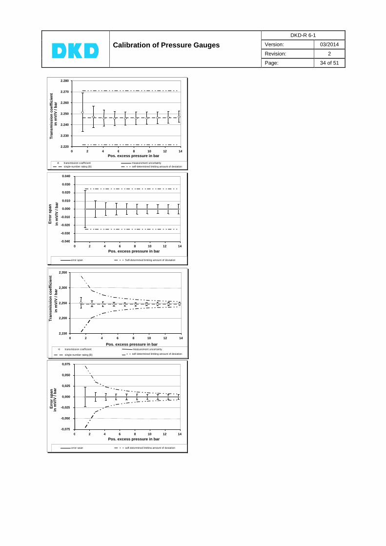
As a rule, error spans result whose magnitudes decrease with increasing pressure. As specification limit, - the maximum calculated error span can be selected (in this case, the specification limits
are shown in the calibration diagram as straight lines parallel to the pressure axis; cf. 9.2.2, Pressure transmitters with electrical output signal,
- Figure 5, upper details) or - the specification limits are described by suitable curves such as hyperbolas or
polynomials (cf. 9.2.2, Pressure transmitters with electrical output signal,

Calibration of Pressure Gauges
DKD-R 6-1
Version: 03/2014
Revision: 2
Page: 28 of 51
- Figure 5, lower details).
Note: The use of pressure-dependent specification limits is not common practice. However, in pressure measurements with the calibrated device in the upper part of the measurement range, it allows the statement of smaller measurement uncertainties.
For calibration items with a nominal parameter (e.g. 2 mV/V) balanced by the manufacturer, the specification limits can alternatively be determined from the associated parameter tolerance. In this case, however, it always has to be checked whether the values of the transmission coefficients determined during calibration, including their associated measurement uncertainties and their systematic deviations from the single-figure indication of the parameter, do not exceed the specification limits.
8.6 Relevant influence quantities of the calibration item for the uncertainty budget
8.6.1 Resolution r
8.6.1.1 Analogue indicating devices
The resolution of the indicating device is obtained from the ratio of the pointer width to the centre distance of two adjacent graduation lines (scale interval). 1/2, 1/5 or 1/10 is recommended as ratio. If the ratio shall be 1/10 (i.e. the estimable fraction of a scale interval), the scale spacing must be 2.5 mm or greater (cf. also DIN 43790).
Note:
The best estimate of an analogue indicating device is determined by visual interpolation. The smallest estimable
fraction of a scale interval is the interpolation component r by which the measurement values can be distinguished.
The variation interval for the best estimate x thus is and with the width of the rectangular
distribution .
8.6.1.2 Digital indicating devices
The resolution corresponds to the digital step, provided that the indication does not vary by more than one digital step when there is no load on the pressure gauge.
Note:
For the determination of the uncertainty contribution, half the value of the resolution a = r/2 is assigned to the half-
width of the rectangular distribution.
8.6.1.3 Fluctuation of readings
If the reading fluctuates by more than the previously determined value of the resolution with the pressure gauge not being loaded, the resolution r is to be taken as half the span of the fluctuation, additionally added with a digital step.
8.6.2 Zero deviation f0
The zero point (unloaded pressure gauge usually at atmospheric pressure) can be set prior to each measurement cycle consisting of an increasing and a decreasing series; it has to be recorded prior to and after each measurement cycle. The reading is to be carried out with the instrument being completely relieved.
In the case of pressure gauges for excess pressure whose initial measuring range is different from the atmospheric pressure (e.g. -1 bar to 9 bar), the drift has to be determined at the zero point.
a x r a x r 2 2a r

Calibration of Pressure Gauges
DKD-R 6-1
Version: 03/2014
Revision: 2
Page: 29 of 51
The determination of the zero point deviation is omitted in case of absolute pressure gauges, where the zero point is not included in the calibration range, e.g. barometers.
The zero deviation is calculated as follows:
(24)
The indices number the measured values x read at the zero points of the measurement series M1 to M6.
8.6.3 Repeatability b'
The repeatability with the mounting not being changed is determined from the difference of the zero signal-corrected measurement values of corresponding measurement series.
(25)
The index j numbers the nominal values of the pressure (j = 0: zero point).
8.6.4 Reproducibility b
The reproducibility with the instrument being mounted repeatedly and the conditions not being changed is determined from the difference of the zero signal-corrected measurement values of corresponding measurement series:
(26)
For index j, see above.
8.6.5 Hysteresis h
When stating mean values, the hysteresis is determined from the difference of the zero point-corrected measurement values of the increasing and decreasing series as follows:
(27)
For index j, see above. The variable n stands for the number of the complete measurement cycles (consisting of an increasing and decreasing series).
0 2 0 1 0 4 0 3 0 6 0 5 0=max , ,, , , , , ,f x x x x x x
0 , 5 , 5 0 , 5 , 6
0 , 3 , 3 0 , 3 , 4 0 , 1 , 1 0 , 1 , 2
, 1
x x x x
x x x x x x x x
n h
j j
j j j j
j mean
j j j
j j j
j j j
b b b
x x x x b
x x x x b
, down , up mean,
0 , 1 , 2 0 , 5 , 6 , down
0 , 1 , 1 0 , 5 , 5 , up
, max
j j j
j j j
j j j
b b b
x x x x b
x x x x b
, down , up mean
0 , 1 , 2 0 , 3 , 4 , down
0 , 1 , 1 0 , 3 , 3 , up
, max

Calibration of Pressure Gauges
DKD-R 6-1
Version: 03/2014
Revision: 2
Page: 30 of 51
9. Evaluation of measurement results and statements in the calibration certificate
The main components of the pressure gauge are each provided with a calibration mark; devices belonging to a measuring chain are each provided with a calibration mark.
In addition to the requirements in DAkkS DKD-5 [12], the calibration certificate must state the following information:
- calibration method (DKD-R 6-1 sequence A, B, C or EN 837 parts 1 and 3) - measurement deviation of the display - pressure-transmitting medium - pressure reference plane on the calibration item - mounting position of the calibration item during calibration - selected settings on the calibration item
The calibration certificate should contain a table of all measurement values, e.g.:
Table 8: Measurement values
Pressure at the height
of the reference
plane of the calibration
item
Displayed value
Calibration sequence A Measurement with 2nd
clamping
Calibration sequence B
Calibration sequence C
M1 (up) M2 (down) M3 (up) M4 (down) M5 (up) M6 (down)
bar, Pascal,
... bar, Pascal, A, V, mV/V, Hz, ...
min. min. min. min. min. min. min.
max. max. max. max. max. max. max.
Column 1 contains the measured pressure values of the standard. Columns 2 to 7 contain the corresponding measurement values displayed by the calibration items according to Figure 1 (Bourdon tube pressure gauge, electrical pressure gauge, pressure transmitter with electrical output) in units of pressure or output in other physical quantities (current, voltage, voltage ratio, frequency, …) or already converted into the quantity of pressure. The further evaluation of the measured values can contain the following parameters: - mean values - zero deviation - repeatability - if applicable, reproducibility - hysteresis - error span - single-figure indication - conformity
ind p
p

Calibration of Pressure Gauges
DKD-R 6-1
Version: 03/2014
Revision: 2
Page: 31 of 51
9.1 Determination of other parameters
9.1.1 Mean values
The mean values with i = up/down, mean are calculated as follows:
for m = 1,3,5
for m = 2,4,6
(28)
where variable l indicates the number of measurement series.
For pressure gauges, where the zero point is not included in the calibration range (e.g. 800 mbar abs to 1200 mbar abs), the zero point correction is omitted when calculating the mean values.
9.1.2 Error span U‘
The error span is the sum of the expanded uncertainty (k = 2) and the amount of the systematic deviation. Due to the systematic component, the error span is assigned the rectangular distribution as distribution shape. The error span is to be determined according to the requirements for the mean values of the increasing and decreasing series and the mean value:
e. g.: (29)
The relative error span W' is formed accordingly.
e. g.: (30)
Note: See footnote 8 on p. 20.
9.1.3 Conformity
If the error spans and the transmission coefficients with attributed measurement uncertainty lie within the indicated specification limits, the conformity according to DAkkS-DKD-5 [12] can be confirmed. Their range of validity has to be indicated. When assessing the compliance with the required specification limits, their origin has to be indicated, e.g. manufacturer-specific specifications according to data sheet, customer demands, inter alia.
9.2 Visualisation of the calibration result
For a better understanding and a quick overview, the calibration result can also be represented graphically.
9.2.1 Bourdon tube pressure gauges, electrical pressure gauges:
The systematic deviation with the expanded measurement uncertainty or the resulting error span, respectively, are to be represented with reference to the specification limit (= error limit) – in the unit of the physical quantity and/or as a related quantity.
x
,i jx
'U U p
' SW W
S
Calibration of Pressure Gauges
DKD-R 6-1
Version: 03/2014
Revision: 2
Page: 32 of 51
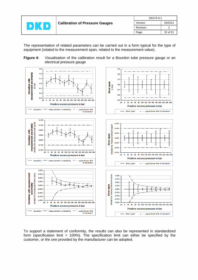
The representation of related parameters can be carried out in a form typical for the type of equipment (related to the measurement span, related to the measurement value).
Figure 4: Visualisation of the calibration result for a Bourdon tube pressure gauge or an electrical pressure gauge
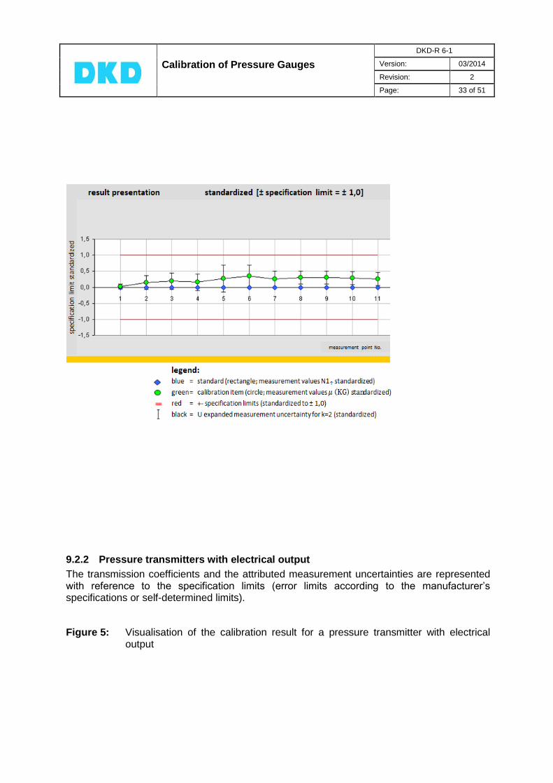
To support a statement of conformity, the results can also be represented in standardized form (specification limit = 100%). The specification limit can either be specified by the customer, or the one provided by the manufacturer can be adopted.
Calibration of Pressure Gauges
DKD-R 6-1
Version: 03/2014
Revision: 2
Page: 33 of 51
9.2.2 Pressure transmitters with electrical output
The transmission coefficients and the attributed measurement uncertainties are represented with reference to the specification limits (error limits according to the manufacturer’s specifications or self-determined limits).
Figure 5: Visualisation of the calibration result for a pressure transmitter with electrical output
Calibration of Pressure Gauges
DKD-R 6-1
Version: 03/2014
Revision: 2
Page: 34 of 51
-0,075
-0,050
-0,025
0,000
0,025
0,050
0,075
0 2 4 6 8 10 12 14 Pos. excess pressure in bar
Err
or
sp
an
in m
V/V
/ b
ar
error span self-determined limiting amount of deviation
2,150
2,200
2,250
2,300
2,350
0 2 4 6 8 10 12 14 Pos. excess pressure in bar
Tra
ns
mis
sio
n c
oe
ffic
ien
t
in m
V/V
/ b
ar
transmission coefficient measurement uncertainty single-number rating (B) self-determined limiting amount of deviation
-0.040 -0.030 -0.020 -0.010 0.000 0.010 0.020 0.030 0.040
0 2 4 6 8 10 12 14 Pos. excess pressure in bar
Err
or
sp
an
in m
V/V
/ b
ar
error span Self-determined limiting amount of deviation
2.220
2.230
2.240
2.250
2.260
2.270
2.280
0 2 4 6 8 10 12 14 Pos. excess pressure in bar
Tra
ns
mis
sio
n c
oe
ffic
ien
t
in m
V/V
/ b
ar
transmission coefficient measurement uncertainty single-number rating (B) self-determined limiting amount of deviation
Calibration of Pressure Gauges
DKD-R 6-1
Version: 03/2014
Revision: 2
Page: 35 of 51
9.3 Limiting values for uncertainty statements
The measurement uncertainty and the error span are calculated according to Section 8. This is valid for all the calibration sequences (A, B, C). Regardless of the result of the calibration, however, the measurement uncertainty is stated for cal. sequence B not smaller than 0.04% of measurement span and for cal. sequence C not smaller than 0.30% of measurement span. For the indication of an error span in a conformity statement according to DAkkS-DKD-5, the value must be given for cal. sequence B not smaller than 0.06% of measurement span and for cal. sequence C not smaller than 0.60% of measurement span. The measurement uncertainty and the error span for the calibration sequence A remain unaffected by these limiting values. They are indicated as actually calculated. In case of measuring devices for which specifications of the measurement value or combined specifications are stated, the limiting values are to be applied using the specification limit at the upper limit of the measurement range.
Calibration of Pressure Gauges
DKD-R 6-1
Version: 03/2014
Revision: 2
Page: 36 of 51
10. Additional rules and standards
If appropriate, the following rules are to be taken into account for the calibration of pressure gauges. It may also be agreed to carry out the calibration in accordance with individual sections of some of these rules. [1] DIN EN 837 T1 Druckmessgeräte mit Rohrfedern
Maße, Messtechnik, Anforderungen und Prüfung Edition February 1997 (English title: Pressure gauges - Part 1: Bourdon tube pressure gauges; dimensions, metrology, requirements and testing)
[2] DIN EN 837 T3 Druckmessgeräte mit Platten- und Kapselfedern Maße, Messtechnik, Anforderungen und Prüfung Edition February 1997 (English title: Pressure gauges - Part 3: Diaphragm and capsule pressure gauges; dimensions, metrology, requirements and testing)
[3] DIN 16086 Elektrische Druckmessgeräte Druckaufnehmer, Druckmessumformer, Druckmessgeräte Begriffe und Angaben in Datenblättern Edition January 2006 (English title: Electrical pressure measuring instruments - Pressure transmitters, pressure measuring instruments - Concepts, specifications on data sheets)
[4] DIN 43790 Grundregeln für die Gestaltung von Strichskalen und Zeigern Edition January 1991 (English title: Basic principles for the design of line scales and pointers)
[5] [6]
EURAMET cg-3 EURAMET cg-17
Calibration of Pressure Balances Version 1.0 (03/2011) Guideline on the Calibration of Electromechanical Manometers Version 2.0 (03/2011)
General
[8] JCGM 200:2008 International vocabulary of metrology -- Basic and general concepts and associated terms (VIM) (identical with ISO/IEC Guide 99:2007) JCGM 200:2008 Corrigendum (2010) http://www.bipm.org/en/publications/guides/vim.html
[9] DIN: 2010 Internationales Wörterbuch der Metrologie -- Grundlegende und allgemeine Begriffe und zugeordnete Benennungen (VIM) - German-English version ISO/IEC-Leitfaden 99:2007. Edition 2012. (English title: International vocabulary of metrology – Basic and general concepts and associated terms (VIM))
[10] DIN 1319-1: 1996 Grundlagen der Messtechnik Teil 1: Grundbegriffe (English title: Fundamentals of metrology - Part 1: Basic terminology)
[11] DIN 1319-2: 1999 Grundlagen der Messtechnik Teil 2: Begriffe für die Anwendung von Messgeräten (English title: Fundamentals of metrology - Part 2: Terminology related to measuring equipment)
[12] DAkkS-DKD-5: 2010 Anleitung zum Erstellen eines Kalibrierscheins

Calibration of Pressure Gauges
DKD-R 6-1
Version: 03/2014
Revision: 2
Page: 37 of 51
DAkkS, 1st edition (reissue) (English title: How to create a calibration certificate; not yet available in English)
Measurement uncertainty
[13] JCGM 100:2008 Evaluation of measurement data -- Guide to the Expression of Uncertainty in Measurement (GUM) (identical with ISO/IEC Guide 98-3:2008) http://www.bipm.org/en/publications/guides/gum.html
[14] JCGM 101:2008 Evaluation of measurement data -- Supplement 1 to the "Guide to the expression of uncertainty in measurement" -- Propagation of distributions using a Monte Carlo method (identical with ISO/IEC Guide 98-3:2008/Suppl 1:2008) http://www.bipm.org/en/publications/guides/gum.html
[15] JCGM 104:2009 Evaluation of measurement data -- An introduction to the "Guide to the expression of uncertainty in measurement" and related documents (identical with ISO/IEC Guide 98-1:2009) http://www.bipm.org/en/publications/guides/gum.html
[16] EA-4/02:1999 Expression of the Uncertainty of Measurement in Calibration -- including supplement 1 and 2 European co-operation for Accreditation http://www.european-accreditation.org/content/publications/pub.htm
[17] DIN V ENV 13005:1999
Leitfaden zur Angabe der Unsicherheit beim Messen Beuth Verlag Berlin (English title: Guide to the expression of uncertainty in measurement)
[18] DAkkS-DKD-3:2010 Angabe der Messunsicherheit bei Kalibrierungen 1. Neuauflage, Deutsche Akkreditierungsstelle GmbH http://www.dakks.de/doc_kalibrier
[19] DAkkS-DKD-3-E1:2010
Angabe der Messunsicherheit bei Kalibrierungen, Ergänzung 1, Beispiele, 1. Neuauflage, Deutsche Akkreditierungsstelle GmbH http://www.dakks.de/doc_kalibrier
[20] DAkkS-DKD-3-E2:2010
Angabe der Messunsicherheit bei Kalibrierungen, Ergänzung 2, Beispiele, 1. Neuauflage, Deutsche Akkreditierungsstelle GmbH http://www.dakks.de/doc_kalibrier
[21] DIN 1319-3:1996 Grundlagen der Messtechnik Teil 3: Auswertung von Messungen einer einzelnen Messgröße, Messunsicherheit Beuth Verlag Berlin (English title: Fundamentals of metrology - Part 3: Evaluation of
measurements of a single measurand, measurement uncertainty)
[22] DIN 1319-4:1999 Grundlagen der Messtechnik Teil 4: Auswertung von Messungen, Messunsicherheit Beuth Verlag Berlin (English title: Fundamentals of metrology - Part 4: Evaluation of measurements; uncertainty of measurement)
Calibration of Pressure Gauges
DKD-R 6-1
Version: 03/2014
Revision: 2
Page: 38 of 51
Literature
[23] Weise, K., Wöger, W.: Messunsicherheit und Messdatenauswertung, VCH Weinheim, 1999, ISBN 3-527-29610-7
[24] Adunka, F.: Messunsicherheiten – Theorie und Praxis, Vulkan-Verlag Essen, 2007, ISBN 978-3-8027-2205-9
[25] Special edition from issues 3 and 4 of the PTB-Mitteilungen 111 (2001)
[26] VDI-Berichte (VDI reports)1805, 1867, 1947 u. Tagungsband 2008 (conference proceedings): Messunsicherheit praxisgerecht bestimmen, VDI/VDE-Gesellschaft für Mess- und Automatisierungstechnik, Conferences: 20.-21.11.2003 und 30.11.-01.12.2004 in Oberhof/Thüringen 14.11.-15.11.2006 und 12.-13.11.2008 in Erfurt VDI Verlag GmbH, Düsseldorf 2003/2004/2006 und VDI Wissensforum 2008
[27] Themenhefte Messunsicherheit: tm Technisches Messen, 2/2004 und 5/2005 (Special publication series on the subject of measurement uncertainty)

Calibration of Pressure Gauges
DKD-R 6-1
Version: 03/2014
Revision: 2
Page: 39 of 51
Annex A Estimate of the measurement uncertainty to be attributed to the values of
the pressure balance under conditions of use11
For a pressure balance under standard conditions, the values and the attributed expanded
uncertainty are to be taken from the calibration certificate (issued, for example, by
PTB). When operating the device under conditions of use, corrections regarding the relevant
influence quantities are to be applied to the values, and to these corrections, too, a
measurement uncertainty has to be attributed. Model of measurement12:
(31)
(32)
Uncertainty budget
with the relevant influence quantities for the pressure value of the standard: temperature,
thermal linear expansion coefficient for the piston and cylinder, acceleration due to gravity
and deformation coefficient. The sensitivity coefficients have been calculated with the
approximations usual for practical applications and for the most common case = .
Table A1: Partial uncertainty budget for the correction of the pressure values of the
pressure balance
Quantity
Best esti-mate
Half-width
Probability distribution
Divisor
Standard uncertainty
Sensitivity coefficient
Uncertainty contribution
Unit
Temperature rectangle
bar
Thermal linear expansion coefficient
rectangle
bar
Acceleration due to gravity
rectangle
bar
Deformation coefficient
rectangle
bar
bar
11
See 7 on page 19
12 See also EURAMET cg-3; Appendix C
1
0
a1
,
1 1 20 C
n
i
e
m gi
m ip g h
A p t
Fl a
iXix a
)( iX ig
ixu ic u yi
Kt a t 3 21
3tu t a 2tc p ( )t tu c u t
a 3 21
3u a
2 20 Cc t p u c u
g ag 3 21
3gu g a c
p
gg ( )g gu c u g
a 3 21
3u a
2c p ( )u c u
Y y 2 2 2 2
korr1 t gu u u u u

Calibration of Pressure Gauges
DKD-R 6-1
Version: 03/2014
Revision: 2
Page: 40 of 51
Note: 1. In calibration certificates issued by PTB for pressure balances, the contribution of the uncertainty of the numerical value of
the deformation coefficient to the uncertainty of the pressure measurement at reference temperature has already been taken into account.
2. By using portal measuring devices, it is possible to measure the local acceleration due to gravity in a particular place with a relative uncertainty of a few ppm. If such an exact measurement value is available, and in view of the usually much larger relative uncertainty of the value of the cross-sectional area, it may be acceptable to neglect the uncertainty contribution of the acceleration due to gravity.
3. In relation to the force of inertia gm acting in the vacuum, the buoyancy correction is of the order 1,510-4. Changes in the
air density at a particular location due to the weather normally do not exceed 2 %, corresponding to a relative contribution to the measurement uncertainty of 3 ppm. In relation to the uncertainty of the cross-sectional area of 50 ppm that is usually indicated in calibration certificates, this contribution is negligible and, in general, does not justify the metrological effort
necessary for its determination (refer to chapter 6. Ambient conditions, Note).
Uncertainty budget
with the influence qualities relevant for the determination of the hydrostatic pressure due to a difference in altitude
Table A2: Partial uncertainty budget with the relevant influence quantities for determining the hydrostatic pressure due to a difference in altitude
Quantity
Best esti-mate
Half-width
Probability distribution
Divisor
Standard uncertainty
Sensitivity coefficient
Uncertainty contribution
Unit
Determination of the density
difference rectangle
bar
Determination of the
acceleration due to gravity
rectangle
bar
Determination of the
difference in altitude
rectangle
bar
bar
Expanded uncertainty (k = 2) for the values realized by a pressure balance under conditions of use:
(33)
Note: In addition to the corrections given here as an example, further corrections and associated contributions to the measurement uncertainty may have to be considered, e.g. the uncertainty of the residual gas pressure measurement for absolute pressure balances, or the pressure dependence of the density of the pressure-transmitting medium in the measurement of major hydraulic pressures.
iXix a
)( iX ig
ixu ic u yi
Fl
a
a
a
3 Fl a
2 21
3u a a c g h ( )u c u
gga 3 21
3gu g a gc h g gu c u g
h ha 3 21
3hu h a hc g ( )h hu c u h
Y y
Calibration of Pressure Gauges
DKD-R 6-1
Version: 03/2014
Revision: 2
Page: 41 of 51
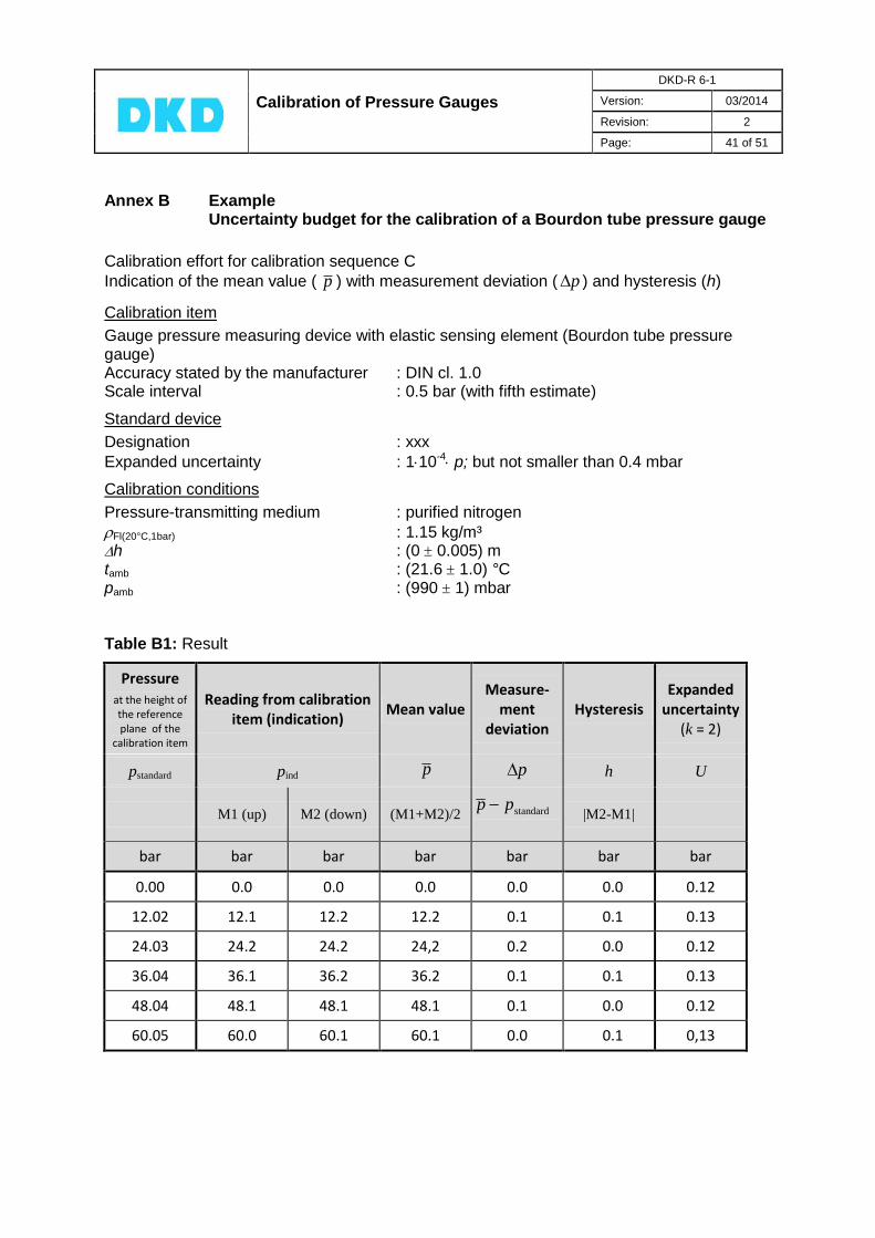
Annex B Example
Uncertainty budget for the calibration of a Bourdon tube pressure gauge
Calibration effort for calibration sequence C
Indication of the mean value ( ) with measurement deviation ( ) and hysteresis (h)
Calibration item
Gauge pressure measuring device with elastic sensing element (Bourdon tube pressure gauge) Accuracy stated by the manufacturer : DIN cl. 1.0 Scale interval : 0.5 bar (with fifth estimate)
Standard device
Designation : xxx
Expanded uncertainty : 110-4 p; but not smaller than 0.4 mbar
Calibration conditions
Pressure-transmitting medium : purified nitrogen
Fl(20°C,1bar) : 1.15 kg/m³ h : (0 0.005) m tamb : (21.6 1.0) °C pamb : (990 1) mbar
Table B1: Result
Pressure at the height of the reference plane of the
calibration item
Reading from calibration item (indication)
Mean value Measure-
ment deviation
Hysteresis Expanded
uncertainty (k = 2)
pstandard pind h U
M1 (up) M2 (down) (M1+M2)/2
|M2-M1|
bar bar bar bar bar bar bar
0.00 0.0 0.0 0.0 0.0 0.0 0.12
12.02 12.1 12.2 12.2 0.1 0.1 0.13
24.03 24.2 24.2 24,2 0.2 0.0 0.12
36.04 36.1 36.2 36.2 0.1 0.1 0.13
48.04 48.1 48.1 48.1 0.1 0.0 0.12
60.05 60.0 60.1 60.1 0.0 0.1 0,13
p p
p p
standard p p

Calibration of Pressure Gauges
DKD-R 6-1
Version: 03/2014
Revision: 2
Page: 42 of 51
Table B2: Uncertainty budget for load step p = 60.05 bar
Quantity Best
estimate Width of
distribution Divisor
Standard uncertainty
Sensitivity coefficient
Uncer-tainty
contribu-tion
Variance
bar bar²
60.05 bar 2 3.00·10
-3 bar -1 3.00·10
-3 9.02·10
-6
* 0.999997 2 K 5.77·10
-1 K
-1.32·10-3
bar/K 7.63·10
-4 5.82·10
-7
** 0 1.0·10
-2 m 2.89·10
-3 m
-6.89·10-3
bar/m 1.99·10
-5 3.95·10
-10
60.05 bar 0.1 bar 5.77·10
-2 bar 1 5.77·10
-2 3.33·10
-3
0 0.0 bar 0 1 0 0
0 0.0 bar 0 1 0 0
0 0.1 bar 2.89·10-2
bar 1 2.89·10-2
8.33·10-4
0.00 bar Standard uncertainty u or variance u
2, respectively 6.46·10
-2
0.00 bar Expanded uncertainty (k = 2) 0.13 bar
* Taking into account the temperature-dependent superficial expansion coefficient of the piston-cylinder system (+)
** Taking into account the pressure-dependent gas density (approximation)
with T = 273.15 K
For the correction of the pressures realized by the standard device, the following data were used (calculation in accordance with Annex A): tK : (21.6 1.0) °C
g : (9.812533 0,000020) ms-² + : (22.0 1.1)·10-6 K-1
Note: The calculated expanded measurement uncertainty for the load step p = 60.05 bar of U = 0.13 bar corresponds to a relative expanded uncertainty of W = 0.22%. According to chapter 9.3 “Limiting values for uncertainty statements“, the value stated in the calibration certificate for a calibration according to sequence C (repeatability and reproducibility cannot be determined) must not be smaller than a value of W = 0.30%; this corresponds to an expanded uncertainty of U = 0.18 bar.
iX ix 2a iu x ic iu y 2u
3
3
3
3
3
3
p 32 1017,4 iu
p U k u
tT
Tp
tp bar1
K20abs
C,1bar20,
hysteresis δ p
repeatability δ p
zero deviation δ p
ind p
standard, h p
standard, t p
standard p

Calibration of Pressure Gauges
DKD-R 6-1
Version: 03/2014
Revision: 2
Page: 43 of 51
Annex C Example
Uncertainty budget for the calibration of a digital electrical pressure gauge
Calibration effort for calibration sequence B
Indication of the mean value ( ) with measurement deviation ( ), repeatability (b') and hysteresis
(h) Electrical pressure gauge with suppressed zero point
Calibration item
Electrical pressure gauge with suppressed zero point Accuracy stated by the manufacturer : 0.03 % of the mean value Resolution : 0.001 mbar
Standard device
Designation : xxx
Expanded uncertainty (standard) : 110-4p but not smaller than 0.005 mbar
Calibration conditions
Pressure-transmitting medium : air
Fl(20°C,1bar) : 1.19 kg/m³ h : (0 0.005) m tamb : (21.6 1.0) °C pamb : (990 1) mbar
Table C1: Result
Pressure at the height
of the reference
plane of the calibration
item
Reading from calibration item (indication)
Mean value
Measure-ment
deviation
Repeat-ability
Hyster-esis
Expanded uncer-tainty (k = 2)
pstandard pind b' h U
M1
(up)
M2
(down)
M3
(up)
((M1+M3)/
2+M2)/2 (M3-M1) (M2-M1)
mbar mbar mbar mbar mbar mbar mbar mbar mbar
50.085 49.850 49.861 49.834 49.852 -0.233 0.016 0.011 0.024
130.191 129.984 130.007 129.967 129.991 -0.200 0.017 0.023 0.029
330.460 330.301 330.335 330.284 330.314 -0.146 0.017 0.034 0.045
530.731 530.616 530.654 530.600 530.631 -0.100 0.016 0.038 0.063
730.990 730.892 730.933 730.879 730.909 -0.081 0.013 0.041 0.082
931.272 931.184 931.226 931.172 931.202 -0.070 0.012 0.042 0.10
1131.138 1131.050 1131.094 1131.046 1131.071 -0.067 0.004 0.044 0.12
1331.413 1331.330 1331.359 1331.337 1331.346 -0.067 0.007 0.029 0.14
1531.673 1531.630 1531.656 1531.629 1531.643 -0.030 0.001 0.026 0.16
p p
p p
standard p p
Calibration of Pressure Gauges
DKD-R 6-1
Version: 03/2014
Revision: 2
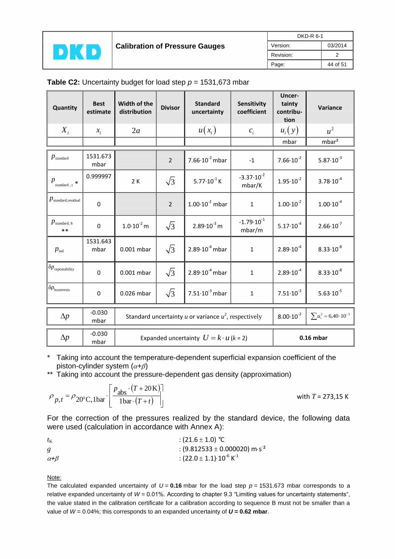
Page: 44 of 51
Table C2: Uncertainty budget for load step p = 1531,673 mbar
Quantity Best
estimate Width of the distribution
Divisor Standard
uncertainty Sensitivity coefficient
Uncer-tainty
contribu-tion
Variance
mbar mbar²
1531.673 mbar
2 7.66·10-2
mbar -1 7.66·10-2
5.87·10-3
0.999997
2 K 5.77·10
-1 K
-3.37·10-2
mbar/K 1.95·10
-2 3.78·10
-4
0 2 1.00·10
-2 mbar 1 1.00·10
-2 1.00·10
-4
** 0 1.0·10
-2 m 2.89·10
-3 m
-1.79·10-1
mbar/m 5.17·10
-4 2.66·10
-7
1531.643 mbar
0.001 mbar 2.89·10
-4 mbar 1 2.89·10
-4 8.33·10
-8
0 0.001 mbar 2.89·10
-4 mbar 1 2.89·10
-4 8.33·10
-8
0 0.026 mbar 7.51·10
-3 mbar 1 7.51·10
-3 5.63·10
-5
-0.030 mbar
Standard uncertainty u or variance u2, respectively 8.00·10
-2
-0.030 mbar
Expanded uncertainty (k = 2) 0.16 mbar
* Taking into account the temperature-dependent superficial expansion coefficient of the piston-cylinder system (+)
** Taking into account the pressure-dependent gas density (approximation)
with T = 273,15 K
For the correction of the pressures realized by the standard device, the following data were used (calculation in accordance with Annex A):
tK : (21.6 1.0) °C
g : (9.812533 0.000020) ms-²
+ : (22.0 1.1)10-6 K-1
Note:
The calculated expanded uncertainty of U = 0.16 mbar for the load step p = 1531.673 mbar corresponds to a
relative expanded uncertainty of W = 0.01%. According to chapter 9.3 “Limiting values for uncertainty statements“,
the value stated in the calibration certificate for a calibration according to sequence B must not be smaller than a
value of W = 0.04%; this corresponds to an expanded uncertainty of U = 0.62 mbar.
iX ix 2a iu x ic iu y 2u
3
3
3
3
3
p 32 1040,6 iu
p U k u
tT
Tp
tp bar1
K20abs
C,1bar20,
hysteresis δ p
repeatability δ p
ind p
standard, h p
standard,residual p
standard , t * p
standard p

Calibration of Pressure Gauges
DKD-R 6-1
Version: 03/2014
Revision: 2
Page: 45 of 51
Annex D Example
Uncertainty budget for the calibration of a pressure transmitter with electrical output13
Calibration effort for calibration sequence A with second clamping
Indication of the mean value ( ) from increasing and decreasing series, of repeatability (b'),
reproducibility (b), hysteresis (h), transmission coefficient S and deviation (S).
Calibration item
Pressure transmitter with electrical output Accuracy stated by the manufacturer : 0.01 % of the upper limit of the measuring range
Standard device
Designation : xxx
Expanded uncertainty : 110-4p but not smaller than 1 mbar
in the measuring temperature range in the pressure reference plane of the calibration item at the place of installation (g = gloc)
Auxiliary measuring device
Digital compensator : xxx Expanded uncertainty U(A) : 0,00005 mV/V
[A: Indication in mV/V Uind/GUSp with G = 1 and U(G) = 0]
Calibration conditions Pressure-transmitting medium : white oil
Fl(20°C) : (855 40) kg/m³ in measuring range up to 200 bar h : (0 0.005) m
tamb : (20 1) °C pamb : (990 1) mbar
13
In the following example, the measurement uncertainty is estimated with related values according to the product/quotient model (eq. 16). Alternatively, the sum/difference model (eq. 8) can be selected when the measurement deviations of the output signal of the pressure transducer from the values calculated according to the nominal characteristic curve are considered. Here, the results of the uncertainty estimates show quantitative agreement.
p

Calibration of Pressure Gauges
DKD-R 6-1
Version: 03/2014
Revision: 2
Page: 46 of 51
Table D1: Measurement data
Pressure at the height of the reference plane of the
calibration item pstandard
Indication Adigital compensator
M1 (up) M2 (down) M3 (up) M4 (down) M5 (up) M6 (down)
bar mV/V mV/V mV/V mV/V mV/V mV/V
0.000 0.00000 -0.00003 0.00000 0.00002 0.00000 -0.00002
20.010 0.20009 0.20026 0.20019 0.20033 0.20021 0.20032
40.022 0.40026 0.40063 0.40032 0.40067 0.40033 0.40064
60.033 0.60041 0.60094 0.60049 0.60097 0.60049 0.60092
80.045 0.80053 0.80118 0.80062 0.80120 0.80062 0.80110
100.056 1.00063 1.00139 1.00072 1.00135 1.00075 1.00125
120.068 1.20074 1.20149 1.20080 1.20141 1.20082 1.20132
140.079 1.40080 1.40158 1.40089 1.40150 1.40090 1.40133
160.091 1.60082 1.60157 1.60091 1.60148 1.60091 1.60126
180.102 1.80084 1.80148 1.80097 1.80135 1.80091 1.80111
200.113 2.00079 2.00100 2.00088 2.00114 2.00086 2.00087
Table D2: Evaluation
Pressure at the
height of the
reference plane of
the calibration
item
Output signal A: Mean value
Zero deviation Repeatability Reproducibility Hysteresis Relative
expanded uncertainty
pstandard f0,rel b'rel brel hrel W(pstandard)
Mi/6 |max|/ |max|/ |max|/ (1/3 )·|hi| *)
bar mV/V # # # # #
0.000 -0.00001 # # # # #
20.010 0.20023 1.5E-04 5.0E-04 6.0E-04 7.0E-04 1.0E-04
40.022 0.40048 7.5E-05 1.5E-04 1.7E-04 8.6E-04 1.0E-04
60.033 0.60070 5.0E-05 1.3E-04 1.3E-04 8.0E-04 1.0E-04
80.045 0.80088 3.7E-05 1.1E-04 1.1E-04 7.1E-04 1.0E-04
100.056 1.00102 3.0E-05 9.0E-05 1.5E-04 6.3E-04 1.0E-04
120.068 1.20110 2.5E-05 1.1E-04 1.5E-04 5.2E-04 1.0E-04
140.079 1.40117 2.1E-05 9.3E-05 1.9E-04 4.3E-04 1.0E-04
160.091 1.60116 1.9E-05 8.7E-05 2.0E-04 3.5E-04 1.0E-04
180.102 1.80111 1.7E-05 1.0E-04 2.1E-04 2.3E-04 1.0E-04
200.113 2.00092 1.5E-05 4.5E-05 7.0E-05 8.0E-05 1.0E-04
*) in the pressure reference plane of the calibration item
p
p p p p

Calibration of Pressure Gauges
DKD-R 6-1
Version: 03/2014
Revision: 2
Page: 47 of 51
Table D3: Result
Pressure at the height of the reference plane of the calibration item
Transmission coefficient
Deviation Relative
expanded uncertainty
Expanded uncertainty
Error span
pstandard S S W(S) U(S) U´(S)
= V/p = S-S' = 2[wi2(S)]
0,5 = W(S)S = U+S
bar (mV/V)/bar (mV/V)/bar # (mV/V)/bar (mV/V)/bar
0.000 # # # # #
20.010 0.0100067 5.2E-06 6.2E-04 6.2E-06 1.1E-05
40.022 0.0100064 4.9E-06 5.3E-04 5.3E-06 1.0E-05
60.033 0.0100062 4.7E-06 4.9E-04 4.9E-06 9.6E-06
80.045 0.0100053 3.8E-06 4.4E-04 4.4E-06 8.2E-06
100.056 0.0100045 3.0E-06 3.9E-04 3.9E-06 7.0E-06
120.068 0.0100035 2.0E-06 3.4E-04 3.4E-06 5.3E-06
140.079 0.0100027 1.2E-06 3.0E-04 3.0E-06 4.2E-06
160.091 0.0100016 4.5E-08 2.6E-04 2.6E-06 2.7E-06
180.102 0.0100005 -1.0E-06 2.2E-04 2.2E-06 3.2E-06
200.113 0.0099990 -2.5E-06 1.3E-04 1.3E-06 3.8E-06
Single-figure indication:
S' = 0.0100015 (mV/V) / bar
Table D4: Uncertainty budget for load step p = 100,056 bar
Quantity Best estimate Width of the distribution
Divisor Standard
uncertainty Sensitivity coefficient
Uncer-tainty
contribu-tion
Variance
*
100,056 bar 20 mbar 2 5.00·10
-5 -1 5.00·10
-5 2.50·10
-9
1,00102 mV/V 0,00010 mV/V 2 2.50·10-5
1 2.50·10-5
6.25·10-10
1 3.0·10
-5
8.66·10
-6 1 8.66·10
-6 7.50·10
-11
1 9.0·10
-5 2.60·10
-5 1 2.60·10
-5 6.76·10
-10
1 1.5·10-4
4.33·10
-5 1 4.33·10
-5 1.87·10
-9
1 6.3·10
-4 1.82·10
-4 1 1.82·10
-4 3.31·10
-8
0,0100046 Rel. standard uncertainty w or variance w
2, respectively 1.9710
-4 3.8810
-8
0,0100046 Relative expanded uncertainty (k = 2) 3.9·10
-4
iX ix 2a iw x ic iw y 2
iw
3
3
3
3
S
S W k w
hysteresis K
reproducibility K
repeatability K
zero deviation. K
standard p

Calibration of Pressure Gauges
DKD-R 6-1
Version: 03/2014
Revision: 2
Page: 48 of 51
The pressure dependence of the oil density has been neglected.
For the load step p = 100.056 bar, the expanded uncertainty of the determination of the transmission coefficient is calculated as follows:
U(S)|100 bar = W S = 3.910-4 0.01000455 (mV/V)/ bar = 3.910-6 (mV/V)/ bar
The specification limit is, for example, ±0.13 % of the transmission coefficient.
Figure D1: Visualisation of the transmission coefficients
0.00998
0.00999
0.01000
0.01001
0.01002
0 20 40 60 80 100 120 140 160 180 200 220
Positive excess pressure in bar
Tra
ns
mis
sio
n c
oe
ffic
ien
t
in (
mV
/V)
/ b
ar
Transmission coefficient Measurement uncertainty Single-figure indication (B) Self-determined upper/lower limit of deviation
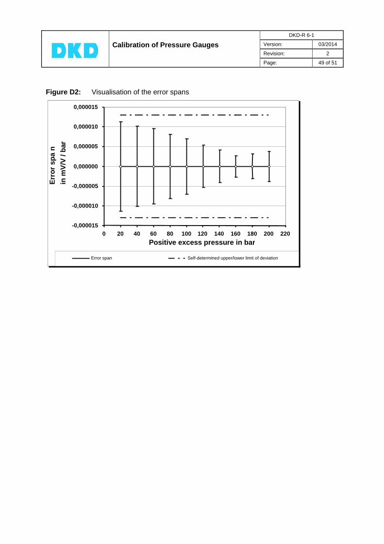
Calibration of Pressure Gauges
DKD-R 6-1
Version: 03/2014
Revision: 2
Page: 49 of 51
Figure D2: Visualisation of the error spans
-0,000015
-0,000010
-0,000005
0,000000
0,000005
0,000010
0,000015
0 20 40 60 80 100 120 140 160 180 200 220
Positive excess pressure in bar
Err
or
sp
a n
in m
V/V
/ b
ar
Error span Self-determined upper/lower limit of deviation
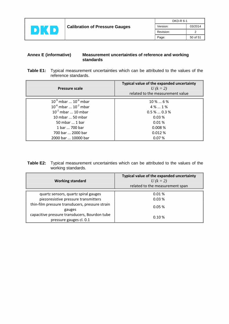
Calibration of Pressure Gauges
DKD-R 6-1
Version: 03/2014
Revision: 2
Page: 50 of 51
Annex E (informative) Measurement uncertainties of reference and working standards
Table E1: Typical measurement uncertainties which can be attributed to the values of the
reference standards.
Pressure scale Typical value of the expanded uncertainty
U (k = 2) related to the measurement value
10-9 mbar ... 10-6 mbar 10 % ... 6 % 10-6 mbar ... 10-2 mbar 4 % ... 1 % 10-2 mbar ... 10 mbar 0.5 % ... 0.3 % 10 mbar ... 50 mbar 0.03 %
50 mbar ... 1 bar 0.01 % 1 bar ... 700 bar 0.008 %
700 bar ... 2000 bar 0.012 % 2000 bar ... 10000 bar 0.07 %
Table E2: Typical measurement uncertainties which can be attributed to the values of the working standards.
Working standard Typical value of the expanded uncertainty
U (k = 2) related to the measurement span
quartz sensors, quartz spiral gauges 0.01 % piezoresistive pressure transmitters 0.03 %
thin-film pressure transducers, pressure strain gauges
0.05 %
capacitive pressure transducers, Bourdon tube pressure gauges cl. 0.1
0.10 %

Calibration of Pressure Gauges
DKD-R 6-1
Version: 03/2014
Revision: 2
Page: 51 of 51
Annex F Recalibration intervals (recommendation) It is the user who is responsible for fixing, and complying with, an appropriate period for repeating the calibration. Under normal conditions of use, the following recalibration periods are recommended: Piston pressure gauges 5 years
Bourdon tube pressure gauges, class > 0.6 2 years
Electrical pressure gauges > 0.5 % of measurement span 2 years
Pressure transmitters with electrical output > 0.5 % of measurement span 2 years
Bourdon tube pressure gauges, class 0.6 1 year
Electrical pressure gauges 0.5 % of measurement span 1 year
Pressure transmitters with electrical output 0.5 % of measurement span 1 year
Regardless of these periods, the calibration item is to be recalibrated, among other things, if it has been subjected to overloading outside its permissible overload limit, after a repair, after improper handling which might affect the measurement uncertainty, or if other reasons exist.