Embed Size (px)
Citation preview
PI 30.22-1
Electrical Equipment - COurse PI 30.2
TRANSFORMERS
OBJECTIVES
On completion of this module the student will be able to:
I. Briefly explain. in writing. the terms 'hysterisis loss" and "eddycurrent loss".
2. Recall. in writing, two factors which make it necessary for a transformerto be cooled.
3. Briefly. state. in writing. two consequences of insufficient coolingin transformers.
4. Given a diagram. identify and briefly explain in one or two sentencesthe purpose of each component in a power transformer.
5. Briefly state, in writing. the methods used for the cooling oftransformers.
6. In writing. identify which transformers within NGD. use oil-water'heat exchanger cooling.
7. Briefly explain, in writing. the operation of an oil-water heatexchanger type of cooling system.
B. a)
b)
Recall, in writing. one problem which may occur with an oil-waterheat exchanger type of cooling system;Explain. in writing. what causes this problem to develop and howit can be eliminated.
g. Recall, in writing, two advantages and two disadvantages of using mineraloil for transformer cooling.
10. Recall, in writing, four contaminations which may occur in transformeroil.
II. Briefly explain. in writing, how each of four contaminants affectstransformer performance.
12. Briefly explain. in writing how each of four contaminants in transformeroil is detected.
13. Briefly, in writing, explain the function of a tap changer and how a tapchanger performs this function.
14. If given a tap changer schematic and a set of voltage variations,select the correct tap to be used.
January 1990 I ITPO.OI
PI 30.22-1
1. Introduction
This lesson will introduce the reader to:
(a) A short review of transformer theory.(b) Methods used for the cooling of transformers.(e) A sectional view of a power transformer.(d) The common problems associated with transformer
insulating oil and the their respective detectionmethods.
(e) Tap changers.
2. Transformer Theory Review
For a detailed discussion on transformer theory,refer to the PI 263 course notes.
Turnsratio (a) Primary number of turns (N]) ... Primary Voltage (V])
• Secondary m.mber of turns (NZ) Secondary Voltage (V2)
Secondary current (12)- Primary current (11)
Total core loss = Eddy current loss + Hysteresis loss.Core loss is a constant quantity. It does not varywith changes in the load current.
Totalcopper ... Primary copper losS(I12Rl) + Secondary copper losS(I22R.2)loss
Copper loss is not a fixed quantity, it changeswith the load current.
- 2 -
PI 30.22-1
3. Transformer Cooling
3.1 Why Cooling is Needed
In the transformer, heat is produced by thefollowing two factors:
(a)" Core loss (considered to be fixed).(b) 12R loss, Which is also referred to, as copper losses.
The 12R loss changes as the load current changes.
If the heat produced by the above two factors isnot removed effectively then:
(1) insulation failure will occur, or(ii) transformer will have to be derated to prevent
damage to the transformer.
Since both of these circumstances mentioned areundesirable, effective cooling methods must be employedto remove this heat from the transformer.
3.2 Cooling Methods
The common cooling methods used in NGD are listedbelow.
(a) For dry type transformers.
(1) Self-air cooled: The transformer is placed in itshousIng and the heat is removed by the naturalconvection of surrounding air and through heatradiation. This method is used for thetransformers rated up to 3MVA.
(1i) Forced air cooled: The transformer is placed inIts housing and air is circulated through it, bymeans of blowers. This method is used fortransformers rated up to 15 MVA in size.
- 3 -
3.2
(b)
PI 30.22-1
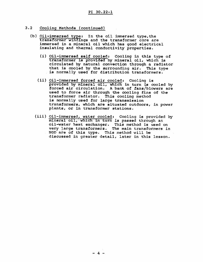
Cooling Methods (continued)
Oil-immersed ty~e: In the oil immersed type, thetransformer win Ings and the transformer core areimmersed in a mineral oil which has good electricalinsulating and thermal conductivity properties.
(1) Oil-immersed self cooled: Cooling in this type oftransformer is provIded by mineral oil, which iscirculated by natural convection through a radiatorthat is cooled by the surrounding air. This typeis normally used for distribution transformers.
(ii) Oil-Immersed forced air cooled: Cooling isprovided by mineral oil, which in turn is cooled byforced air circulation. A bank of fans/blowers areused to force air through the oooling fins of thetransformer radiator. This cooling methodis normally used for large transmissiontransformers, which are situated outdoors, in powerplants, or in transformer stations.
(iii) Oil-immersed, water cooled: Cooling is provided bymineral oll,-which in turn is passed through anoil-water heat exchanger. This method is used onvery large transformers. The main transformers inNGD are of this type. This method will bediscussed in greater detail, later in this lesson.
- 4 -

PI 30.22-1
Notes
- 5 -
PI 30.22-1
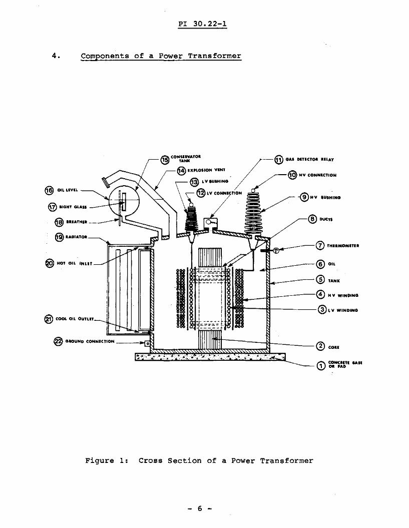
4. Components of a Power Transformer
® ."'® TANk
@) MY WINOING
\,-v;~~u-----®TH••MOMITU
----flf-------® L V WINDING
~-@ GAl DlTlero-. IILAY
. @ MY CONNlerlON
@ LVIUIHING
@LVCONN.etlON
11'2\ (ONIIlY"TOIv.::J ,..NK
@IXI'l.OIION VINT
@ ....OI ...'O.
@ "'''''".1 ----~Ic:::::::::::::::_~
@ liGHT GlAn __-,-
@ HOT OIL INLIT
@ OILUVIL
@ COOL OIL OUTur
Figure 1: Cross Section of a Power Transformer
- 6 -
PI 30.22-1
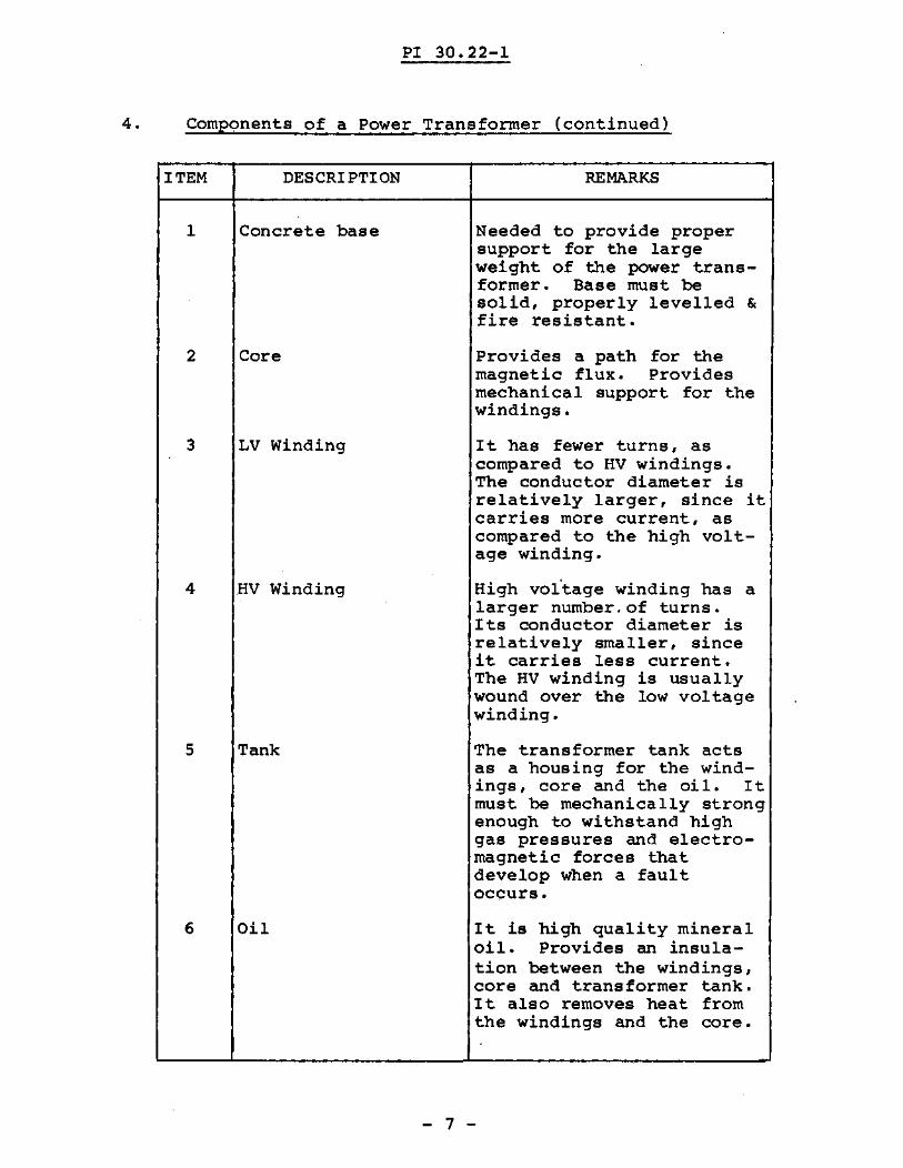
4. Components of a Power Transformer (continued)
ITEM
1
2
3
4
5
6
DESCRIPTION
Concrete base
Core
LV Winding
HV Winding
Tank
Oil
REMARKS
Needed to provide propersupport for the largeweight of the power transformer. Base must besolid, properly levelled &fire resistant.
Provides a path for themagnetic flux. Providesmechanical support for thewindings.
It has fewer turns, ascompared to HV windings.The conductor diameter isrelatively larger, since itcarries more current, ascompared to the high voltage winding.
High val'tage winding has alarger number.of turns.Its conductor diameter isrelatively smaller, sinceit carries less current.The HV winding is usuallywound over the low voltagewinding.
The transformer tank actsas a housing for the windings, core and the oil. Itmust be mechanically strongenough to withstand highgas pressures and electromagnetic forces thatdevelop when a faultoccurs.
It is high quality mineraloil. Provides an insulation between the windings,core and transformer tank.It also removes heat fromthe windings and the core.
- 7 -
PI 30.22-1
f:\, COHcun\V 011 "AD
® ."'® ,...® NV WINDING
@DUClS
I----il-------@LV WINDING
~ CONIIW...'OI G:\\b? TAHIt ~-- \!.JI ..... OITielOI ilL...,.
@tXI'\.OIION VINT
@ MV CONN'eTlDN@ LV.IIIMINO
@ ~v CONNlenON
@ ,.UlH•• ----,~~::::::::::::::o~
~ II"'DI""CH.·--'-,Ir~~~~ji~
@ Ol~ I.IVIL
@) HOT OIL INLIT
@ COOL OIL DurLiT
Figure 2: Cross Section of a Power Transformer
- 8 -
PI 30.22-1
4. Components of a Power Transformer (continued)
ITEM
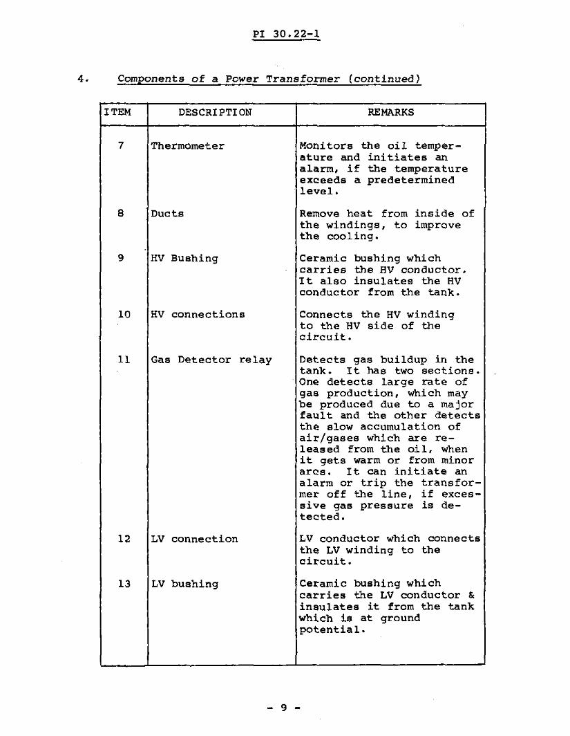
7
8
9
10
11
12
13
DESCRIPTION
Thermometer
Ducts
HV Bushing
HV connections
Gas Detector relay
LV connection
LV bushing
REMARKS
Monitors the oil temperature and initiates analarm, if the temperatureexceeds a predeterminedlevel.
Remove heat from inside ofthe windings, to improvethe cooling.
Ceramic bushing whichcarries the HV conductor.It also insulates the HVconductor from the tank.
Connects the HV windingto the HV side of thecircuit.
Detects gas buildup in thetank. It has two sections.One detects large rate ofgas production, which maybe produced due to a majorfault and the other detectsthe slow accumulation ofair/gases which are released from the oil, whenit gets warm or from minorarcs. It can initiate analarm or trip the transformer off the line, if excessive gas pressure is detected.
LV conductor which connectsthe LV winding to thecircuit.
Ceramic bushing whichcarries the LV conductor &insulates it from the tankwhich is at groundpotential.
- 9 -
PI 30.22-1
@Ducn
--® H Y IUIH ,NO
JJL-----@ ."rL._---@,...
:JlJ,.""'------® fHllMOMU••
_---H------@)NVWIHD.---{:l--------® L V WINDING
~ (ONIIIIVA'OlI t::\& TANK ~~ GAl DlUCTOI RUA'
@ IX'LOIION VINT @ NV CONNICTION
@ LV'USNI"G
@ ~Y CONNI TION
@ •••ATHIIl -"1IL.:::::::::::::__
@1"0I""0II
@ liGHT Q.LAIS __~t:-=i#--j
@> HOT OIL INLET
@ OIL Llyn
@ COOl. OIL Dunn
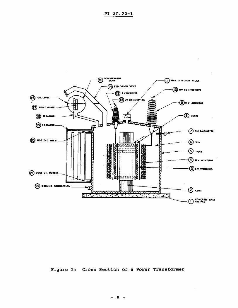
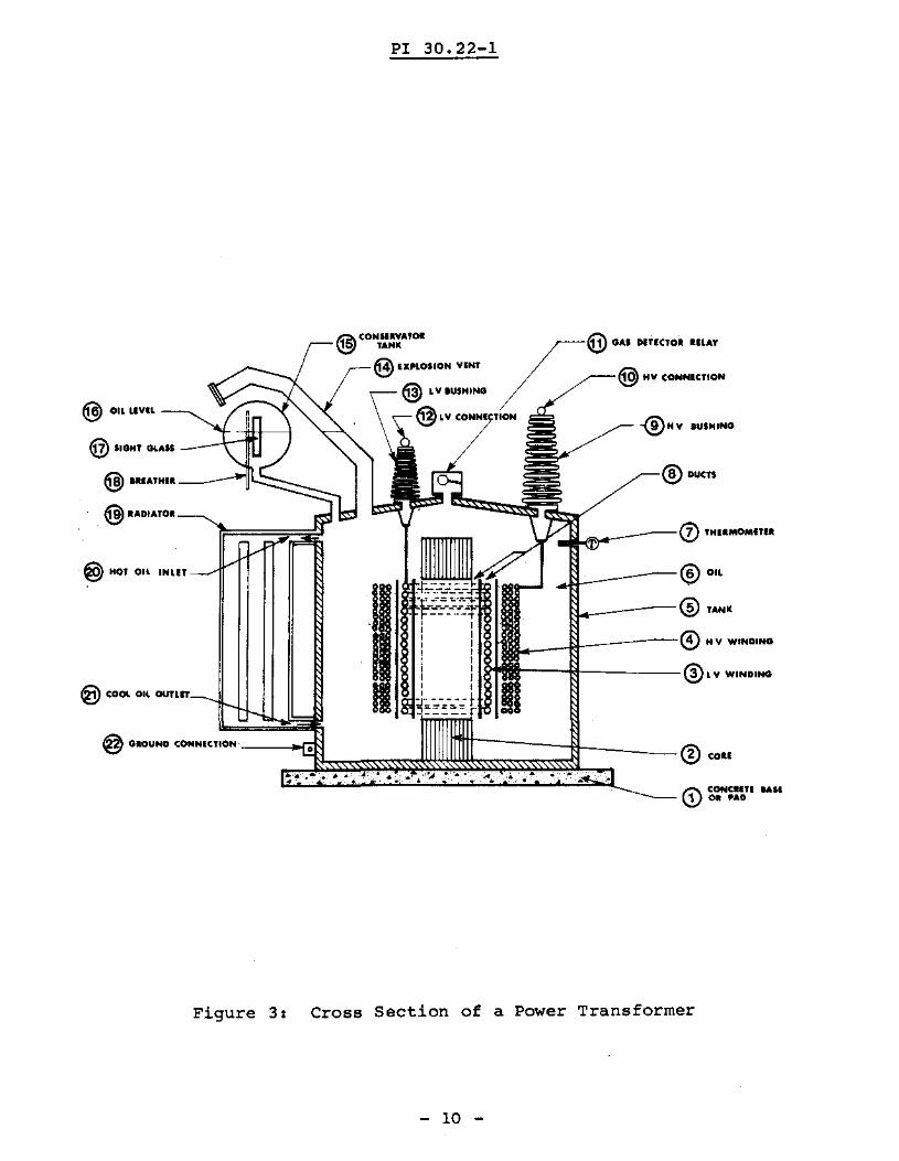
Figure 3: Cross Section of a Power Transformer
10
PI 30.22-1
4. Components of a Power Transformer (continued)
ITEM
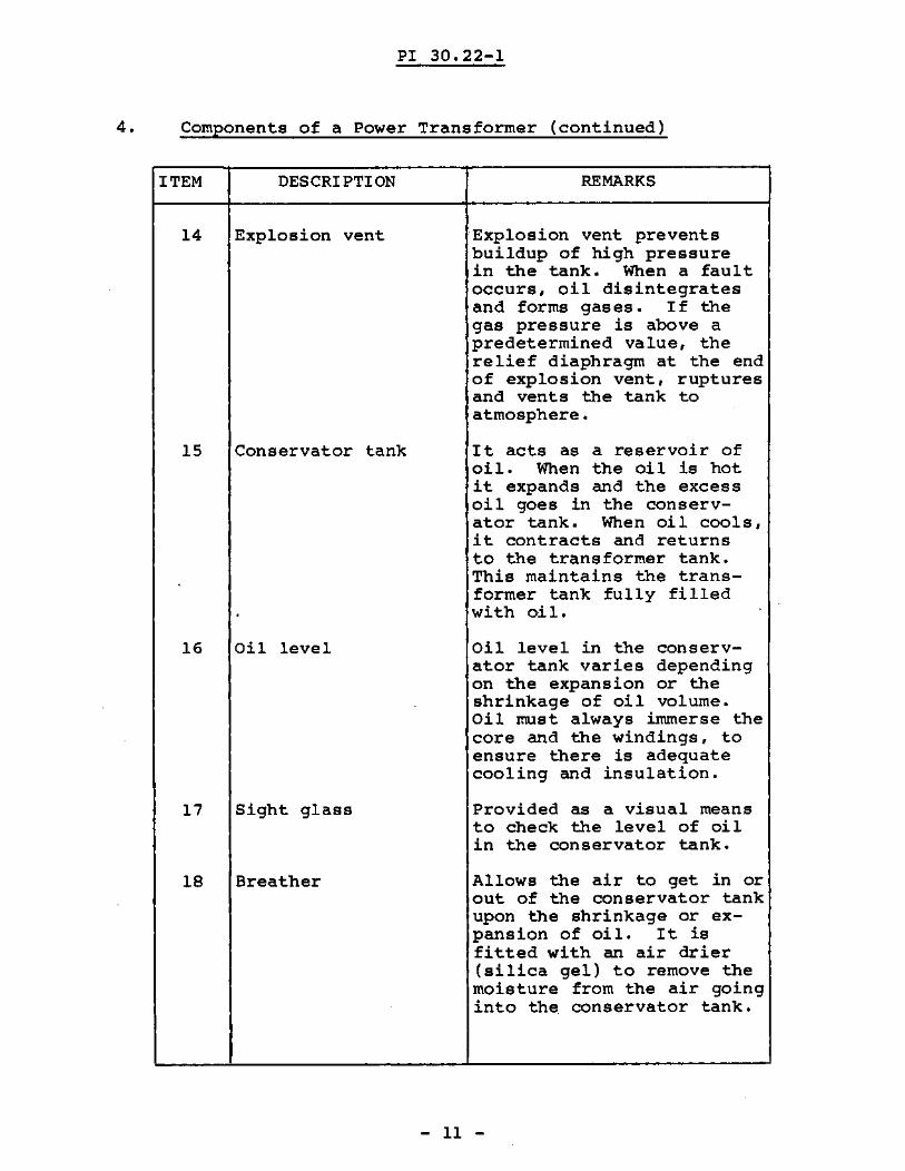
14
15
16
17
18
DESCRIPTION
Explosion vent
Conservator tank
Oil level
Sight glass
Breather
REMARKS
EXplosion vent preventsbuildup of high pressurein the tank. When a faultoccurs, oil disintegratesand forms gases. If thegas pressure is above apredetermined value, therelief diaphragm at the endof explosion vent, rupturesand vents the tank toatmosphere.
It acts as a reservoir ofoil. When the oil is hotit expands and the excessoil goes in the conservator tank. When oil cools,it contracts and returnsto the transformer tank.This maintains the transformer tank fully filledwith oil.
Oil level in the conservator tank varies dependingon the expansion or theshrinkage of oil volume.Oil must always immerse thecore and the windings, toensure there is adequatecooling and insulation.
Provided as a visual meansto check the level of oilin the conservator tank.
Allows the air to get in orout of the conservator tankupon the shrinkage or expansion of oil. It isfitted with an air drier(silica gel) to remove themoisture from the air goinginto the conservator tank.
- 11 -
I·
PI 30.22-1
® DUCTS
-®H V IUIHING
),oV,,Jikl'J"-------0 THIIMOMITIl
Jl~----®."tl.._----:--® 'ANK
!.-__-+1--------0 H v WINDING
,...---lil-------® L V WINOINO
/-@ 010. M:Tlcr~ IILAY
/ / @NV CONNIeTlON
"..@CON,::...'OI
® IX",05lON YINT
@ LV.USNlNO
@LVCONN
@ IIOMT GlASS _~~-=1i1t-l
@ TH•• ----jl~::::::::::::::::.,
@ D1 TOII __,,~~:=;;~;,ji
@) Hot on INUT
@ OIL UVIL __,
@ COOL OIL ounn
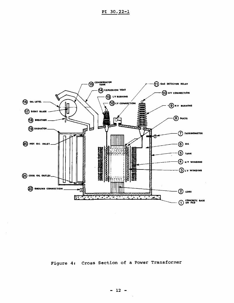
Figure 4: Cross Section of a Power Transformer
12

PI 30.22-1
4. Components of a Power Transformer (continued)
ITEM
19
20
21
22
DESCRIPTION
Radiator
Hot oil inlet
Cool oil outlet
Ground connection
REMARKS
This is a type of heat exchanger which is used toprovide cooling for thehot oil. Hot oil circulates through the coolingfins and air circulationaround the radiator provides the cooling.
Hot oil enters the radiatorhere from the transformertank, due to convection.
After oil circulatesthrough the radiator it becomes cool and returns tothe tank at this point.
Transformer tank is connected to the ground(earth)at this ~ermin~l, to provide safety to personnel.
- 13 -
PI 30.22-1
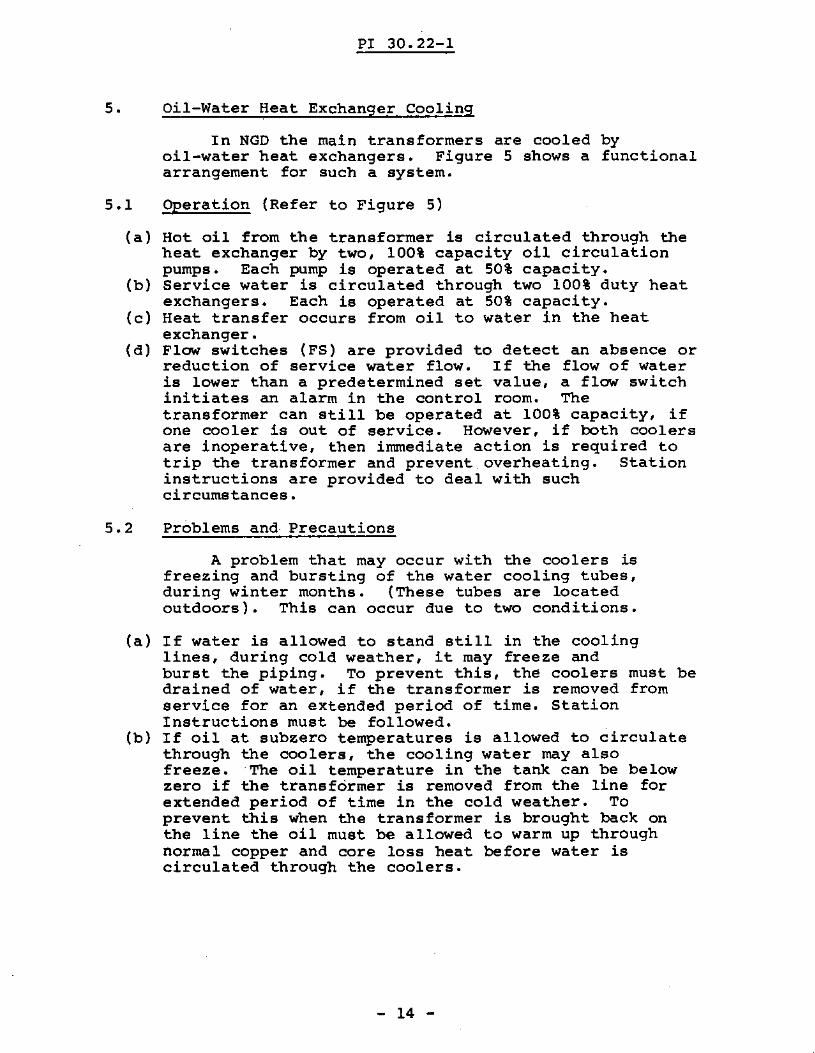
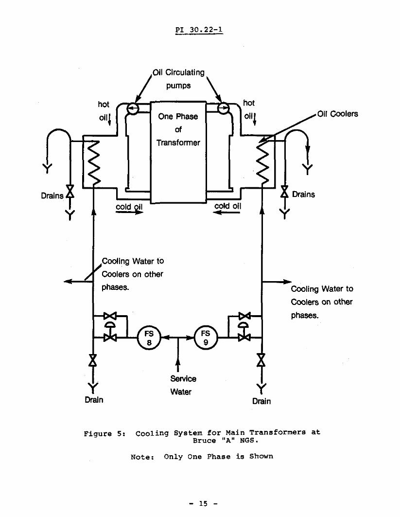
5. Oil-Water Heat Exchanger Cooling
In NGD the main transformers are cooled byoil-water heat exchangers. Figure 5 shows a functionalarrangement for such a system.
5.1 Operation (Refer to Figure 5)
(al Hot oil from the transformer is circulated through theheat exchanger by two, 100% capacity oil circulationpumps. Each pump is operated at 50% capacity.
(b) Service water is circulated through two 100% duty heatexchangers. Each is operated at 50% capacity.
(e) Heat transfer occurs from oil to water in the heatexchanger.
(d) Flow switches (FS) are provided to detect an absence orreduction of service water flow. If the flow of wateris lower than a predetermined set value, a flow switchinitiates an alarm in the control room. Thetransformer can still be operated at 100% capacity, ifone cooler is out of service. However, if both coolersare inoperative, then immediate action is required totrip the transformer and prevent overheating. Stationinstructions are provided to deal with suchcircumstances.
5.2 Problems and· Precautions
A problem that may occur with the coolers isfreezing and bursting of the water cooling tubes,during winter months. (These tubes are locatedoutdoors). This can occur due to two conditions.
(a) If water is allowed to stand still in the coolinglines, during cold weather, it may freeze andburst the piping. To prevent this, the coolers must bedrained of water, if the transformer is removed fromservice for an extended period of time. StationInstructions must be followed.
(b) If oil at subzero temperatures is allowed to circulatethrough the coolers, the cooling water may alsofreeze. The oil temperature in the tank can be belowzero if the transformer is removed from the line forextended period of time in the cold weather. Toprevent this when the transformer is brought back onthe line the oil must be allowed to warm up throughnormal copper and core loss heat before water iscirculated through the coolers.
- 14 -
PI 30.22-1
Oil Circulating
pumps
Drains
y
011 Coolers(]scr=~=:-l:i:r"'lhotOne Phase all~
of
Transformer
y
Drains
y cold 'j!1 cold all.. y
Cooling Water to
Coolers on other
phases. Cooling Water to
Coolers on other
phases.
FS ......L-f:'<t--19
yDrain
service
Water yDrain
Figure 5: Cooling System for Main Transformers atBruce "A" NGS.
Note: Only One Phase is Shown
- 15 -
PI 30.22-1
6. Advantages and Disadvantages of Transformer Oil
(a) Advantages:
(1) Transformer oil is a good electrical insulator.(ii) Transformer oil has good thermal conductivity which
allows efficient removal of heat.
(b) Disadvantages:
(1) Mineral oil is a fire hazard, hence, indoortransformers should not be of the oilimmersed type.
(ii) Oil is a polution hazard. Any leaks in the tank orduring oil handling can result in pollution of theof the environment.
iii) Synthetic oil, called IlAskerel ll, is non-flammable,
but it is linked to serious health problems. Itsuse has been banned and restricted to existinginstallations, only.
7. Oil Contamination and Detection Methods
Oil must be kept clean and free of contaminationin order for it to perform as an insulator. Thefollowing factors will affect oil performance.
7.1' Moisture
Moisture is a major problem with oil which is usedas an insulation for in electrical equipment. Anexcess of moisture greatly reduces the insulatingproperties of oil. Moisture contents of 0.06% reducethe insulating ability of oil to half. The maximumacceptable moisture level in oil is 35 parts permillion. Extensive care is taken to prevent moisturecontamination. Some of these are listed below:
(a) During shipping and assembly, care is taken to preventmoisture from getting into the tank, or the windings,or the oil.
(b) Air dryers are installed on the breather of theconservator tank. These dryers can be of a chemical ordehumidifier type.
(0) In an oil-water heat exchanger, oil pressure ismaintained above the water pressure to prevent thewater from leaking into the oil.
- 16 -
PI 30.22-1
(d) Regular checks are made on oil samples in order todetect moisture. One method uses a dielectric tester.During this test the oil sample is sUbjected to a fixedpotential difference for a given amount of time. Ifarcing does not occur, then the oil is considered to besatisfactory.
7.2 Oxidation of Oil
When oil is heated above 7SoC andoxygen, it oxidizes and forms sludge.presents the following problems.
exposed toOxidation
(a)
(b)
Sludge formed in the oil restricts the flow of oil inthe cooling ducts and reduces the cooling efficiency.Oil becomes acidic which reduces its insulation qualityand life.
Oxidation is detected by an acidity test of theoil. The result of this test is compared to the valuefound in a previous test. A progressively increasingacidity content indicates that oxidation of the oil istaking place. Once the acidity increases over a set,acceptable limit,the oil must be refiltered orreplaced.
7.3 Dissolved Gases
Localized hot spots, due to the burning ofinsulation or sparks causes oil temperature, inlocalized areas, to become high enough to cause oildisintegration. The formation of carbon and othergases occurs. Some of this gas is dissolved in the oiland causes the conductivity of oil to increase. Inorder to determine if localized hot spots are presentin the transformer, a chemical analysis of the oil isperformed. The presence of carbon and other gases canthus be detected. A presence of these, indicateslocalized burning of insulation and the transformertank must be opened to correct this problem.
7.4 Oil Level
Oil level in the transformer may drop due toevaporation or leaks. A low oil level can damage thetransformer. A sight glass or level indicator isprovided on the transformer tank or the conservatortank. Regular checks are made on the oil level.
- 17 -
PI 30.22-1
8. Transformer Tap Changes
8.1 What is a Tap Changer
VLoed
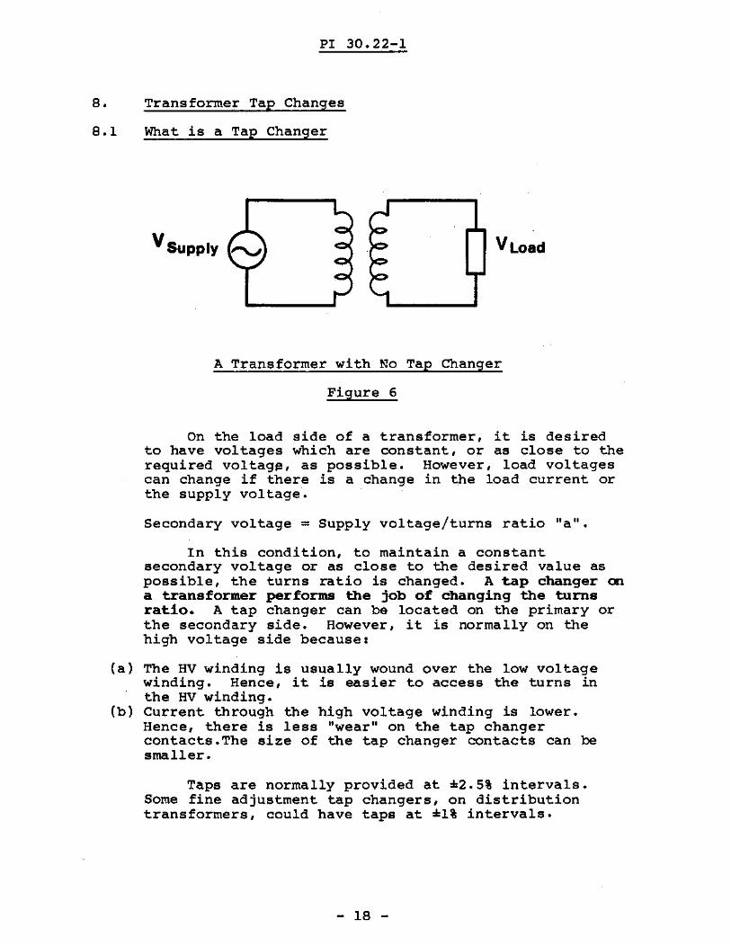
A Transformer with No Tap Changer
Figure 6
On the load side of a transformer, it is desiredto have voltages Which are constant, or as close to therequired voltag~, as possible. However, load voltagescan change if there is a change in the load current orthe supply voltage.
Secondary voltage = Supply voltage/turns ratio "a ".
In this condition, to maintain a constantsecondary voltage or as close to the desired value aspossible, the turns ratio is changed. A tap changer ona transformer performs the job of changing the turnsratio. A tap changer can be located on the primary orthe secondary side. However, it is normally on thehigh voltage side because:
(a) The HV winding is usually wound over the low voltagewinding. Hence, it is easier to access the turns inthe HV winding.
(b) Current through the high voltage winding is lower.Hence, there is less Ilwear " on the tap changercontacts.The size of the tap changer contacts can besmaller.
Taps are normally provided at =2.5% intervals.Some fine adjustment tap changers, on distributiontransformers, could have taps at =1% intervals.
- 18 -

PI 30.22-1
8.2 Tap Changer Operation: Tap Changer in Primary
Consider the tap changer in Figure 7(A) and followthe steps below.
(al When the supply voltage is nominal, the tap changerwill be at the tap marked 0%.
(b) Consider the secondary voltage increasing 2-1/2% aboveits nominal value. To maintain the secondary voltageconstant, the tap changer shifts to the tap marked +2-1/2%. This increases the number of turns in theprimary by 2-1/2%. Hence, the turns ratio increases.The secondary voltage therefore decreases.
(c) Consider the load voltage decreasing by 2-1/2% fromnominal. The tap changer shifts to the - 2-1/2% tap.This decreases the number of turns in the primary by2-1/2%. The turns ratio, "a" decreases. Hence, thesecondary voltage increases.
lJ.8kV
Al60Vl~
~s~• _2
, 0
Top ~_2O-±-,~,--,/
~entageofOinding in UN
Figure ?CA): Tap Changer in the Primary
- 19 -
PI 30.22-1
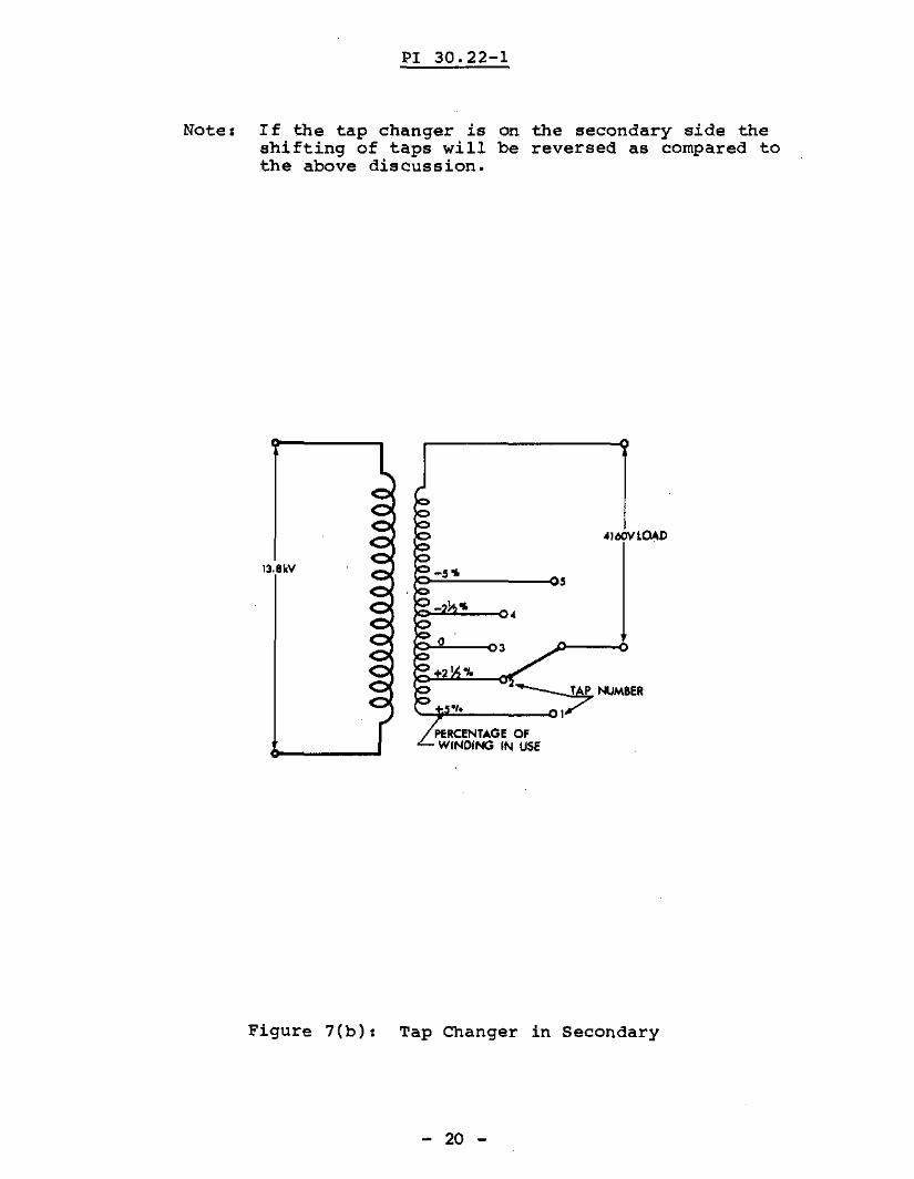
Note: If the tap changer is On the secondary side theshifting of taps will be reversed as compared tothe above discussion.
4JMlYL04D
/<?..O--03
+2 1 -Ie
-to ~NUM8ER
PERCENTAGE OFWINDING IN USE
Figure 7(b): Tap Changer in Secondary
- 20 -
PI 30.22-1
8.3 Types of Tap Changers
There are two types of tap changers.
(a) Off-load tap changer
In NGD, most of the tap changers in transformers are ofthe off-load type. Off-load tap changers, havecontacts Which are not designed to break any current,including the no-load current. Transformers with thistype of tap changing mechanism must be electricallydisconnected from the circuit before the tap ischanged. Tap changing can be manual or motorized.
(b) On-Load Tap Changer
In on-load tap changers, the taps can be changed whilethe transformer is supplying the load. Mechanisms areprovided to prevent damage to the transformer or tothe tap changer.
- 21 -
PI 30.22-1
ASSIGNMENT
1. Explain why cooling is required in transformers (section3.1)
2. List twoformers.
consequences of(Section 3.1)
inefficient cooling in trans-
3. List two cooling methods used for dry type transformersand briefly explain each. (Section 3.2)
- 22 -
PI 30.22-1
4. List three oooling methode used for oil-immersed typetransformers and briefly explain each. (Section 3.2)
5. List the components of a power transformer and give thefunction of each. (Section 4 Figure 1)Use separate sheets.
- 23 -
PI 30.22-1
6. State what type of transformers, in NGD, use anoil-water heat exchanger for cooling. Briefly explainthe operation of such an arrangement. (Sections 5, 5.1)
7. What problemwhat factorseliminated?
may develop withcontribute to it(Section 5.2)
- 24 -
oil-water heatand how can it
exchangers,be

PI 30.22-1
8. List two advantages and two disadvantages of transformeroil. (Section 6).
- 25 -
PI 30.22-1
9. List three contaminants which may be detected intransformer oil. State how each affects transformerperformance and how each is detected. (Section 7.1,7.2. 7.3)
- 26 -
PI 30.22-1
10. State what a tap changer does and how it achieves this.(Section 8.1)
11. From Figure 7(B) indicate the tap position to be usedif.{a} the secondary voltage increases by 5%.
(b) the secondary voltage decreases by 5%.
- 27 -
PI 30.22-1
12. List the two types of tap changers used anddifferentiate between them. (section 8.3)
s. Rizvi
- 28 -

PI 30.22-1
Notes
- 29 -