Embed Size (px)
Citation preview
1
PI Controller for Active Twin-Accumulator Suspension with Optimized Parameters
Based on a Quarter Model
Mohamed A. Hassan * 1, Ali M. Abd-El-Tawwab 1, k. A. Abd El-gwwad 1 and M. M. M. Salem 1
1 Automotive and Tractors Engineering Department, Faculty of Engineering, Minia University,
El-Minia 61111, Egypt.
* Corresponding Authors: E-mail: [email protected]
Abstract:
This paper is primarily studying the behaver of the twin-accumulator suspension over the
conventional passive system focusing on ride quality behavior and road holding. Therefore, a
dynamic modeling of passive and twin-accumulator suspension for a quarter model is
constructed. MATLAB Simulink environment is used to develop the suspension models. The
simulation is applied with two different road disturbances, namely, step input and random input
to disturb the suspension system. The optimum solution is obtained numerically by utilizing a
multi-objective evolutionary strategy algorithm and employing a cost function that seeks to
minimize the RMS value of the body acceleration, the suspension displacement as well as the
dynamic tire load. Moreover, in this work, an active suspension system with PI controller is
presented in order to improve the suspension performance criteria. The simulation results of
passive, optimized twin accumulator suspension and active suspension consist of body
displacement, wheel deflection, vehicle body acceleration, suspension travel and dynamic tire
load are compared and analyzed. Results show that the twin-accumulator suspension system gives
worthwhile improvements in ride behavior compared with the passive suspension. Finally, it can
be observed that the performance of body displacement and wheel displacement can be improved
by using the proposed PI controller.
2
Keywords:
Twin-accumulator suspension, Optimization, Evaluation strategy technique, PI controller.
1. Introduction:
The main target of an automotive suspension system is to provide vehicle support, stability
and directional control during handling maneuvers and provide effective isolation from road
disturbance. Therefore, suspension systems have substantial performance parameters which
should be considered. Firstly, ride Comfort is directly related to the acceleration sensed by
vehicle passengers when traveling on a rough road. Secondly, Body motion, known as bounce,
pitch, and roll of the sprung mass, is created primarily during cornering, breaking besides
maneuvering. Then, Road handling is represented by the contact force of the tire and the road
surface. Finally, suspension travel refers to the relative displacement between the sprung and the
unsprung masses [1-4].
Generally, passive, semi-active and active suspension systems have been utilized to improve
ride comfort of vehicles and their effectiveness have also been demonstrated. In case of passive
suspension, it is not easy to improve dynamics behavior as the problem of passive system is if it
designed heavily damped, road disturbance will be transferred to the vehicle body. On the other
hand, if it considered softly damped, the vehicle will have a poor stability during cornering and
maneuvering. Besides, the performance of the passive suspension depends on the road profile. In
contrast, the active suspension can give better performance of suspension because it has the
ability to adjust itself continuously to adapt with road condition. Better performance can be
achieved by changing the actuator force in order to respond with road input variation.
Whereas a several number of researchers proposed theoretical and experimental studies
describing the behavior of passive, semi-active and active suspension system as well. Abdel-
Tawwab [5] presented a theoretical evaluation for twin accumulator suspension system and the

3
results obtained were compared to those given by conventional passive suspension system. As a
result, the twin accumulator system gave worthwhile improvements when compared to
conventional passive suspension. In order to improve vehicle oscillation, Smith and Wang [6]
proposed a comparative study of several simple passive suspension struts in which each
containing at most one damper and inerter to improve both ride comfort and handling. They
demonstrated that the implemented systems based on a quarter-car model had preferable attitude
compared with a conventional passive suspension strut. Pable and Seshu [7] attempted to find the
best parameters of a passive system which provides a performance as close to an active system as
possible. Optimized passive settings were then obtained using least squares sense to generate
equal suspension force as that of active case. Bo et al [8] developed a twin-accumulator hydro-
pneumatic suspension based on the off-road vehicle and thus the working principles and elements
construct of the developed suspension were studied. And then, they built a mathematical model of
the developed suspension. The ride comfort of the vehicle with the developed suspension was
analyzed theoretically compared with a single accumulator hydro-pneumatic suspension in both
time domain and frequency domain.
Hong Biao and Nan [9] formulated an optimal vehicle suspension design problem with a
quarter-car vehicle dynamic model. An optimization was conducted using Genetic algorithm
technique. The proposed technique was a global optimization technique which was used to find
an optimal design that minimizes an objective function subject to constraints. Mehmood et al [10]
developed a mathematical model of quarter and a half car with a complete state space analysis
and simulated by using MATLAB platform. The damping characteristic of the suspension damper
was optimized in accordance with other vehicle dynamics parameter like sprung mass, unsprung
mass, tire stiffness and damping, suspension stiffness and road input. Tran and Hasegawa [11]
implemented a new design of passive suspension within component element named "inerter" to

4
reduce sprung mass displacement and tire deflection in quarter-car model. The submitted design
was optimized based on the minimization of cost functions for displacement, tire deflection with
constraint function of suspension deflection limitation as well as the energy consumed by the
inerter. Drehmer et al [12] developed a model of a vehicle with eight degrees of freedom
including driver’s seat under a random road profile. Here, particle swarm optimization and
sequential quadratic programming algorithms were utilized to obtain the suspension optimal
parameters at different conditions. They aimed to reduce the weighted RMS vertical acceleration
based on human sensitivity curves. Recently, researchers give more attention in applying active
suspension using several control methods in order to improve vehicle dynamic performance.
Khajavi et al and Agharkakli et al developed an investigation to design an active suspension for a
passenger car by designing LQR controller, which improves performance of the system with
respect to design goals compared to passive suspension system [13, 14]. Choudhury and Sarkar
[15] studied the performance of passive and active suspension system with PID controller.
Therefore, Mathematical modeling of quarter car was done based on a two degree of freedom
system. Rao [16] carried out a study to investigate the performance of a quarter car semi-active
suspension system using PID controller under MATLAB Simulink Model considering the
dynamic system used in this study was a linear system. In his work, two types of road profiles
were used as input for the system. Results showed that the performance of body displacement and
wheel displacement could be improved by using the proposed PID controller.
In this paper, a mathematical modeling of passive, twin-accumulator and active twin-
accumulator with PI controller are established. The aim is to study the behavior of the previous
systems based on different road condition as well as implement an optimization technique called
evaluation strategy attached to the twin-accumulator system. Finally, PI controller is selected to
be applied on the actuator force of the active system and thus the results are analyzed.
5
This paper is organized as follows; brief note on the twin-accumulator suspension is presented
in section 2 while the mathematical modeling of a quarter car suspension model is built in section
3. The road profiles are explained in section 34. In section 5, Simulink structure of suspension
models are discussed then the performance criteria, as well as the model parameters, are listed in
section 6. Whereas, applied PI controller is in section 8 after that the results is presented in
Section 9. Finally, the paper is concluded in section 10.
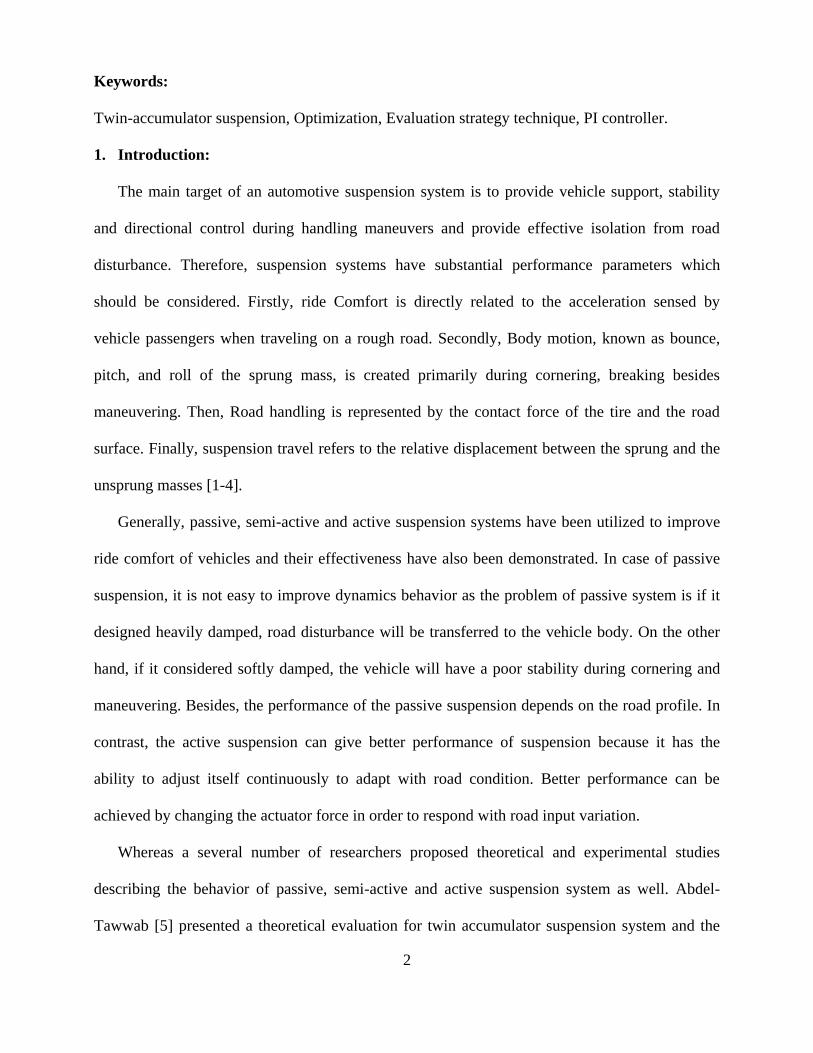
2. Twin-Accumulator Suspension Configuration:
Hydro-pneumatic suspension involves accumulator (flexible components) to generate spring
force and a remote valve block (damping components) to generate damping force. A hydraulic
cylinder replaces the damper strut and springs of the vehicle [17]. The twin-accumulator system
consists of a parallel network of an accumulator and a throttle valve in series with another
accumulator then this series network is parallel with second throttle valve as presented in Fig. 1.
3. Mathematical Modeling
In this work, a quarter car models with two degrees-of-freedom are carried out instead of full
model based on laws of mechanics. It not only leads to simplify the analysis but also represents
most of the features of the full model. Simulation software MATLAB/SIMULINK has been used
to analyze the model.
1 2 3
4 5
Fig. 1. Twin-accumulator system construction.
Part No. Part Name
1 Hydraulic Cylinder
2, 4 Throttle valve
3, 5 Gas accumulator
6
3.1. Modeling assumptions:
Before the establishment of this model, three assumptions in the following should be required:
a) Vehicle near the equilibrium position to make a slight vibration, the spring-elastic element
is a linear function of its displacement; the damping force is a linear function of its speed.
b) The operating conditions are driving at a constant speed on the smooth straight road.
c) Symmetrical to its longitudinal axis line of cars.
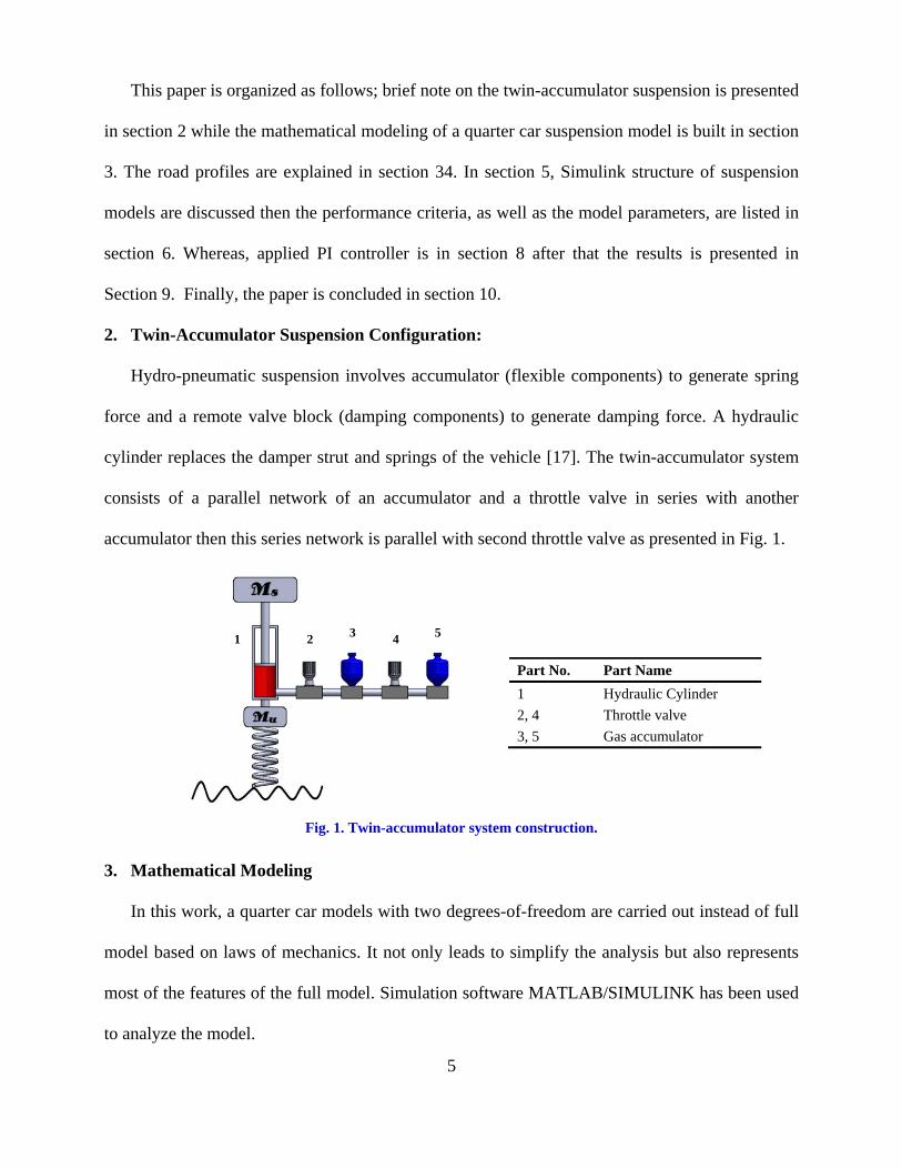
3.2. Conventional suspension system:
Fig. 2.a Shows a quarter car vehicle conventional hydro-pneumatic suspension system. Car
body is denoted as sprung mass and the tire is denoted as un-sprung mass. Single wheel and axle
is connected to the quarter portion of the car body through a spring and damper. The tire is
assumed to have only the spring feature and is in contact with the road terrain at the other end.
The road terrain serves as an external disturbance input to the system.
Fig. 2. Quarter suspension model; (a) passive suspension; (b) twin accumulator suspension system; (c) active
twin-accumulator model.
Based on Newtonian mechanics the equations of the motion for the passive suspension
system are given:
(a) (b) (c)
7
)()()( 11 susuuotuu xxcxxkxxkxm (1)
)()( 11 sususs xxcxxkxm (2)
3.3. Twin-Accumulator Suspension System:
The mathematical model of twin-accumulator suspension based on quarter vehicle model is
presented in Fig. 2.b and the equation of motion can be written as:
)()( 131 suuss xxcxxkxm (3)
)()()( 323231 xxkxxcxxk uus (4)
)()()()( 32321 xxkxxcxxcxxkxm uusuuotuu (5)
3.4. Active twin-accumulator suspension system:
Fig. 2.c shows the equivalent theoretical model to an active suspension system with an
actuator. Therefore, equation of motion that describe this system is established as:
aususs Fxxkxxcxm )()( 321 (6)
)()()( 323231 xxkxxcxxk uus (7)
auusuuotuu Fxxkxxcxxcxxkxm )()()()( 32321 (8)
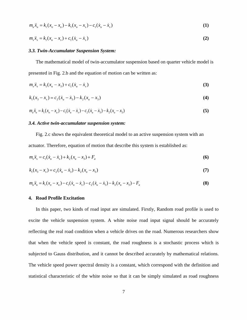
4. Road Profile Excitation
In this paper, two kinds of road input are simulated. Firstly, Random road profile is used to
excite the vehicle suspension system. A white noise road input signal should be accurately
reflecting the real road condition when a vehicle drives on the road. Numerous researchers show
that when the vehicle speed is constant, the road roughness is a stochastic process which is
subjected to Gauss distribution, and it cannot be described accurately by mathematical relations.
The vehicle speed power spectral density is a constant, which correspond with the definition and
statistical characteristic of the white noise so that it can be simply simulated as road roughness
8
time domain model. It is found that there are several ways to generate road elevation time domain
model, such as filtering white noise generation method, random sequence generation method,
filtering superposition method, AR (ARMA) method and fast Fourier inverse transform
generation method (IFFT) [18]. Here, white noise generation method has been selected as it has a
clear physical meaning and it is easy to be simulated.
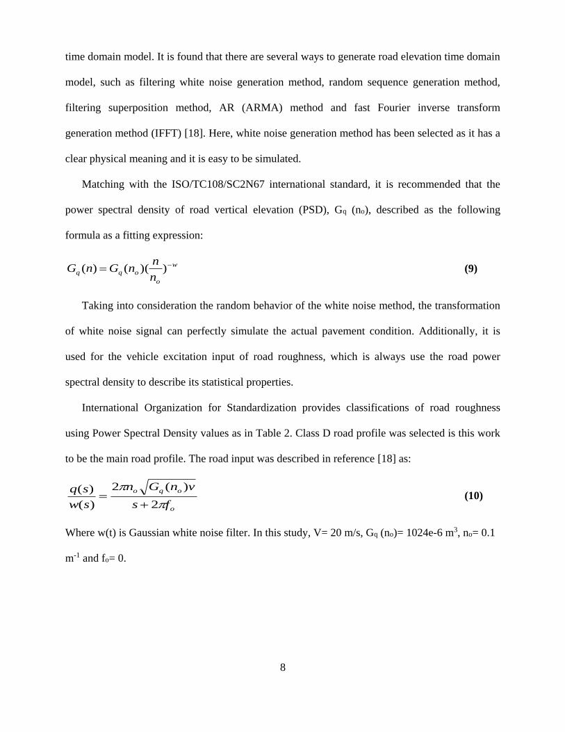
Matching with the ISO/TC108/SC2N67 international standard, it is recommended that the
power spectral density of road vertical elevation (PSD), Gq (no), described as the following
formula as a fitting expression:
w
o
oqqn
nnGnG ))(()( (9)
Taking into consideration the random behavior of the white noise method, the transformation
of white noise signal can perfectly simulate the actual pavement condition. Additionally, it is
used for the vehicle excitation input of road roughness, which is always use the road power
spectral density to describe its statistical properties.
International Organization for Standardization provides classifications of road roughness
using Power Spectral Density values as in Table 2. Class D road profile was selected is this work
to be the main road profile. The road input was described in reference [18] as:
o
oqo
fs
vnGn
sw
sq
2
)(2
)(
)(
(10)
Where w(t) is Gaussian white noise filter. In this study, V= 20 m/s, Gq (no)= 1024e-6 m3, no= 0.1
m-1 and fo= 0.
9
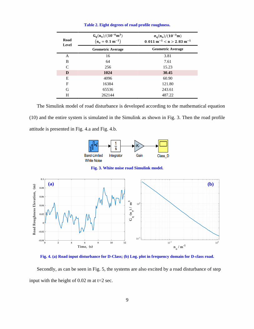
Table 2. Eight degrees of road profile roughness.
Road
Level
𝐆𝐪(𝐧𝐨)/(𝟏𝟎−𝟔𝐦𝟑)
(𝐧𝐨 = 𝟎. 𝟏 𝐦−𝟏)
𝛔𝐪(𝐧𝐨)/(𝟏𝟎−𝟑𝐦)
𝟎. 𝟎𝟏𝟏 𝐦−𝟏 < 𝐧 > 𝟐. 𝟖𝟑 𝐦−𝟏
Geometric Average Geometric Average
A 16 3.81
B 64 7.61
C 256 15.23
D 1024 30.45
E 4096 60.90
F 16384 121.80
G 65536 243.61
H 262144 487.22
The Simulink model of road disturbance is developed according to the mathematical equation
(10) and the entire system is simulated in the Simulink as shown in Fig. 3. Then the road profile
attitude is presented in Fig. 4.a and Fig. 4.b.
Fig. 3. White noise road Simulink model.
Fig. 4. (a) Road input disturbance for D-Class; (b) Log. plot in frequency domain for D-class road.
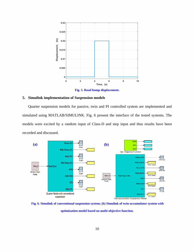
Secondly, as can be seen in Fig. 5, the systems are also excited by a road disturbance of step
input with the height of 0.02 m at t=2 sec.
(a) (b)
10
Fig. 5. Road bump displacement.
5. Simulink implementation of Suspension models
Quarter suspension models for passive, twin and PI controlled system are implemented and
simulated using MATLAB/SIMULINK. Fig. 6 present the interface of the tested systems. The
models were excited by a random input of Class-D and step input and thus results have been
recorded and discussed.
Fig. 6. Simulink of conventional suspension system; (b) Simulink of twin-accumulator system with
optimization model based on multi-objective function.
(a) (b)

11
6. Performance criteria and model parameters
The performance of each suspension system can be assessed quantitatively in terms of three
parameters. These are chosen to represent each of the conflicting requirements of the suspension
and have been widely used and accepted as a measure of system performance [1, 19].The main
model parameters are listed in Table 3.
3.1. Discomfort (ACC)
This provides a single number index of system performance in terms of ride quality. It can be
defined as the R.M.S value of frequency weighted vertical body acceleration.
3.2. Suspension Working Space (SWS)
This parameter is defined as the RMS value of wheel to body displacement su xx and
measures the variation of the displacement about its static position.
3.3. Tire Loading Parameter (DTL)
This parameter is defined as the RMS value of tire load variations from the static value. DTL
can be considered as a measure of road holding ability since a variation in the tire load results in a
varying contact length and consequently a net reduction inside or braking force.
Table 3. Quarter vehicle parameters
Parameters Symbol Value Unit
Sprung mass 𝐦𝐬 300 kg
Unsprung mass 𝐦𝐮 40 kg
Frist Damping coefficient 𝐂𝟏 1000 N.s/m
Frist spring stiffness 𝐤𝟏 15000 N/m
Second Damping coefficient 𝐂𝟐 1000 N.s/m
Second spring stiffness 𝐤𝟐 15000 N/m
Tire stiffness 𝐤𝐭 20000 N/m
7. Implementation of Optimization via Multi-objective function
In this paper, the aim of designing a multi-objective function in active suspension system is to
minimize the difference between the body and tire displacements to provide more comfort against

12
the road disturbance. The objective function has been considered as a combination of ride
comfort and ride safety by taking appropriate weighting factors which are listed in Table 4.
Evaluation strategy technique is carried out to find an optimal solution expressed by the
objective function under the fulfillment of constraint conditions. Fig. 7. illustrates the developed
objective function Simulink model. Table 5. states the lower and upper boundaries of designed
parameters.
Fig. 7. Multi-objective function implementation
Table 5. upper and lower boundary of parameters.
Parameter Upper boundary Lower boundary
𝐂𝟏 2500 900
𝐤𝟏 40000 15000
𝐂𝟐 2500 900
𝐤𝟐 40000 15000
The selected optimization technique (Evaluation strategy technique) is applied and thus the
simulation is carried out with 5, 10 and 50 iterations then the results are presented and discussed.
Considering that, the initial and optimum values of the mentioned parameters over the two-road
excitation is illustrated in Table 6 and Table 7.
Variable BACC DTL SWS
Weighting Factor 0.5 0.45 0.05
Table 4. considered weighting factors.

13
8. PI controller
The benefit of controlled suspension is that a better set of design trade-offs are possible to be
compared with passive suspension. The mathematical representation of simplified PI controller
scheme is given by:
dtteKteKG ipc )()( (11)
Where Gc is the controller output, kp is proportional gain, ki is integral gain, e(t) is input to the
controller and e(t) dt is the time integral of the input signal. Fig. 8.a presents the closed loop
diagram of the selected controller. For evaluating the performance of the applied controller, the
simulations are carried out on the active twin-accumulator suspension model.
In this research, a unity feedback circuit is formed depending on the body acceleration as the
output variable. Taking the set point as zero, the error signal is fed to the controller. The closed
loop block diagram is shown in Fig. 8.b.
Fig. 8. (a) Block diagram of a PI controller in a feedback loop; (b) Simulink of active suspension system with
PI controller.
Table 6. Optimal system parameters for random input
Parameter Initial Value Optimal Value Unit
𝐂𝟏 1000 900 N.s/m
𝐤𝟏 15000 15000 N/m
𝐂𝟐 1000 900 N.s/m
𝐤𝟐 15000 18801 N/m
Table 7. Optimal system parameters for step input
Parameter Initial Value Optimal Value Unit
𝐂𝟏 1000 900 N.s/m
𝐤𝟏 15000 15000 N/m
𝐂𝟐 1000 2196 N.s/m
𝐤𝟐 15000 40000 N/m
(a) (b)
14
Firstly, the proportional and integral terms are summed with initial values to calculate the
output of the PI controller. Then, auto tuning for PI controller has been applied using robust
response tuning method with the MATLAB/Simulink software. Both initial and tuned values of
the controller gains are shown in Table 8. The introduced tuning method is a trial and error
method with a simple and common step due to determine the best value.
Table 8. PI controller gains
Controller
Gains
Initial
Value
Tuned Value Tuned Value
Random Input Step Input
𝐤𝐩 0 0 0
𝐤𝐢 1 1904 800
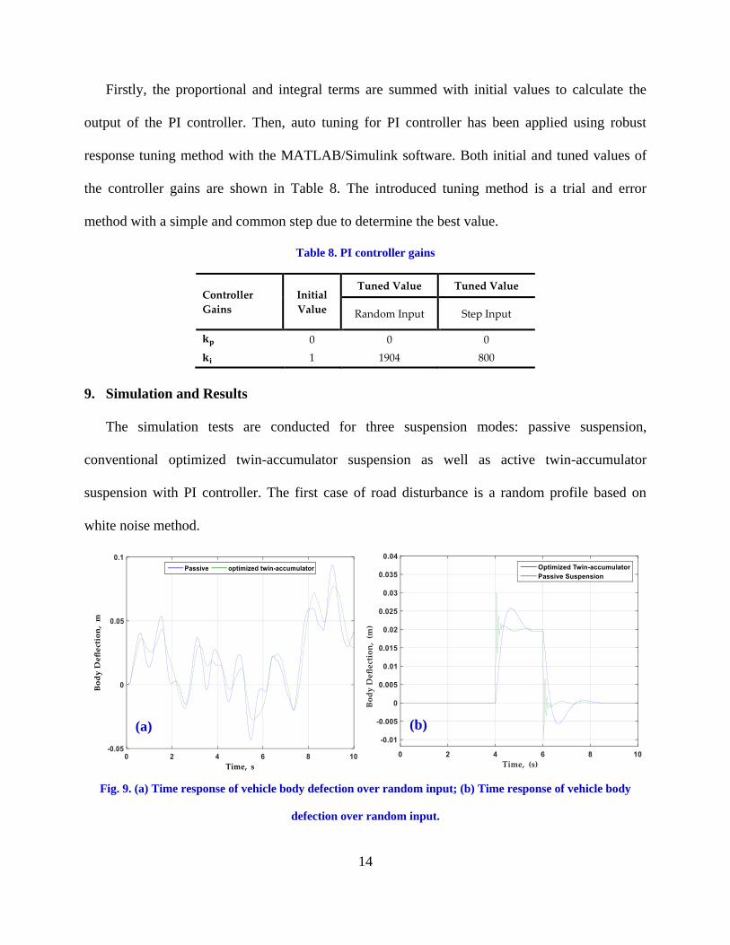
9. Simulation and Results
The simulation tests are conducted for three suspension modes: passive suspension,
conventional optimized twin-accumulator suspension as well as active twin-accumulator
suspension with PI controller. The first case of road disturbance is a random profile based on
white noise method.
Fig. 9. (a) Time response of vehicle body defection over random input; (b) Time response of vehicle body
defection over random input.
(a) (b)
15
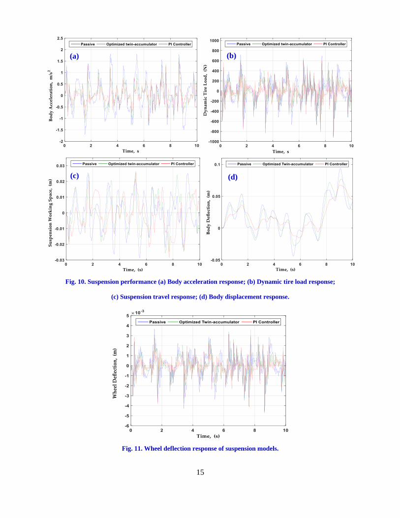
Fig. 10. Suspension performance (a) Body acceleration response; (b) Dynamic tire load response;
(c) Suspension travel response; (d) Body displacement response.
Fig. 11. Wheel deflection response of suspension models.
(a) (b)
(c) (d)

16
Fig. 12. Suspension performance for step road input. (a) Body displacement response; (b) Body acceleration
response; (c) Suspension travel response; (d) Dynamic tire load response.
Fig. 13. Wheel deflection response of step road input.
(a) (b)
(c) (d)

17
Fig. 14. (a) RMS values of performance index over random road; (b) RMS values for step input.
Fig. 9 show that the body deflection is less for the optimized twin-accumulator suspension
than the deflection for the passive suspension in both random and step road profile. After which
the controller is applied, the system performance achieved more improvement as indicated in Fig.
10 and 12. Another behavior category, Fig. 11 and 13 indicate the wheel displacement response
for the two road inputs. It can be seen that the results for optimized twin-accumulator are closely
matched with to PI controlled system. Consequently, the dynamic tire load which is shown in Fig.
10.b and 12.d have the same attitude as the wheel deflection. While the passive suspension
system is worse than the other systems.
As can be observed in Figs. 10.c and 12.c, the suspension working space of the PI controller
system is lower than the twin-accumulator and passive as well. In Figs. 10.a and 12.b, the body
acceleration of the active system with PI controller is more beneficial than the other systems.
10. Conclusion
All in all, in this work, an optimization technique is carried out on the twin accumulator
suspension system so the multi-objective function is developed to minimize the performance
criteria of the system. The PI controller has been successfully implemented in an active twin-
0.702
0.4639
0.3495
Body ACCeleration
0.0116
0.011
0.0102
Suspension Deflection
244.4
207.38
180.16
Dynamic Tire Load
0.351
0.2880.283
Body ACCeleration
0.00364
0.0030.0029
Suspension Deflection
260.7
252.48
250.37
Dynamic Tire Load
Passive Twin Optimization PI Controller
(a) (b)

18
accumulator suspension system through simulation analysis. After that, a comparison between
passive, optimized twin-accumulator and PI controller is presented as well as their performances
are analyzed. The compassion depends on the RMS of the body acceleration, dynamic tire load,
and suspension travel. The performance of twin-accumulator active suspension system with PI
controller has been proven to perform better than the passive suspension system.
11. Proposal for future work
The recommendation for future work is to expand the vehicle dynamic model to a half model
with an active twin-accumulator suspension system to study the pitch attitude. After that, an
advanced control strategy should be designed and expanded to include the body acceleration, the
suspension travel, and the wheel deflection. Implement a regenerative energy harvesting
suspension system depending on the hydraulic based system [20].
Notations
Symbol Definition Unit
𝐦𝐬 Sprung mass kg
𝐦𝐮 Unsprung mass kg
𝐂𝟏 Frist Damping coefficient N.s/m
𝐂𝟐 Second Damping coefficient N.s/m
𝐤𝟏 Frist spring stiffness N/m
𝐤𝟐 Second spring stiffness N/m
𝐤𝐭 Tire stiffness N/m
𝐱𝐬 Sprung mass displacement m
�̈�𝐬 Body acceleration m/s2
𝐱𝐮 Unsprung mass displacement m
�̈�𝐮 Wheel acceleration m/s2
𝐅𝐚 Actuator force N
𝐕 Vehicle speed m/s
𝐪(𝐭) Road profile excitation
𝐰(𝐭) Gaussian white noise filter
𝐤𝐩 Proportional controller gain
𝐤𝐢 Integral controller gain

19
References
[1]. Abdelkareem, M.A., Makrahy, M.M., Abd-El-Tawwab, A.M., EL-Razaz, A., Ali,
M.K.A., and Moheyeldein, M., An analytical study of the performance indices of
articulated truck semi-trailer during three different cases to improve the driver comfort. P
I Mech Eng K-J Mul, 2017. https://doi.org/10.1177/1464419317709895.
[2]. Pratheepa, B. Modeling and simulation of automobile suspension system. in Frontiers in
Automobile and Mechanical Engineering (FAME), 2010. IEEE.
[3]. Ali, M.K.A., Xianjun, H., Elagouz, A., Essa, F., and Abdelkareem, M.A., Minimizing of
the boundary friction coefficient in automotive engines using Al2O3 and TiO2
nanoparticles. J Nanopart Res, 2016. 18(12): p. 377.
[4]. Ali, M.K.A., Abdelkareem, M.A., Elagouz, A., Essa, F., and Xianjun, H., Mini Review on
the Significance Nano-Lubricants in Boundary Lubrication Regime. arXiv preprint
arXiv:170508401, 2017.
[5]. El-Tawwab, A.M.A., Twin-accumulator suspension system. 1997, SAE Technical Paper.
[6]. Smith, M. C., & Wang, F. C. (2004). Performance benefits in passive vehicle suspensions
employing inerters. Vehicle System Dynamics, 42(4), pp. (235-257).
[7]. Pable, M. J., & Seshu, P. (2007). Design of passive suspensions to reduce actuator control
effort. 12thIFToMM World Congress, Besançon (France).
[8]. Yang, B., Chen, S.-z., Wu, Z.-c., Yang, L., and Zhang, B., Development of a twin-
accumulator hydro-pneumatic suspension. J Shanghai Jiaotong Univ, 2010. 15(2): p. 183-
187.
[9]. Yu, H. and Yu, N., Application of genetic algorithms to vehicle suspension design.
Mechanical Engineering Department, The Pennsylvania State University, University Park,
20031-9: p. 1-9.
[10]. Mehmood, A., Khan, A.A., and Mehmood, A., Optimization of Suspension Damping
Using Different Mathematical Car Models. International Journal Of Mechanical
Engineering, 2013. 3(10): p. 1-15.
[11]. Tran, T. T., & Hasegawa, H. (2015). Advanced Passive Suspension with Inerter Devices
and Optimization Design for Vehicle Oscillation. International Journal of Mechanical
Engineering and Robotics Research, 4(4),pp. (354-360).

20
[12]. Drehmer, L.R.C., Paucar Casas, W.J., and Gomes, H.M., Parameters optimisation of a
vehicle suspension system using a particle swarm optimisation algorithm. Vehicle Syst
Dyn, 2015. 53(4): p. 449-474.
[13]. Khajavi, M. N., & Abdollahi, V. Comparison between optimized passive vehicle
suspension system and semi active fuzzy logic controlled suspension system regarding
ride and handling. In Proceedings of world academy of science, engineering and
technology, (2007) 21, pp. (57-61).
[14]. Agharkakli, A., Sabet, G. S., & Barouz, A. Simulation and analysis of passive and active
suspension system using quarter car model for different road profile. International Journal
of Engineering Trends and Technology, (2012) 3(5), pp636-644..
[15]. Choudhury, S. F., & Sarkar, M. R. An Approach On Performance Comparison Between
Automotive Passive Suspension And Active Suspension System (Pid Controller) Using
Matlab/Simulink. Journal of Theoretical & Applied Information Technology, (2012)
43(2),PP. 295-300.
[16]. Rao, K.D., Modeling, Simulation and Control of Semi Active Suspension System for
Automobiles under MATLAB Simulink using PID Controller. IFAC Proceedings
Volumes, 2014. 47(1): p. 827-831.
[17]. Razenberg, J., Modelling of the hydropneumatic suspension system of a rally truck. 2009,
Master Thesis, Eindhoven University of Technology.
[18]. Zhou, Q., Research and Simulation on New Active Suspension Control System. 2013.
[19]. Sharp, R. and Hassan, S., An evaluation of passive automotive suspension systems with
variable stiffness and damping parameters. Vehicle Syst Dyn, 1986. 15(6): p. 335-350.
[20]. Mi, J., Xu, L., Guo, S., Abdelkareem, M.A., and Meng, L. Suspension Performance and
Energy Harvesting Property Study of a Novel Railway Vehicle Bogie with The
Hydraulic-Electromagnetic Energy-Regenerative Shock Absorber. 2017. SAE
International.
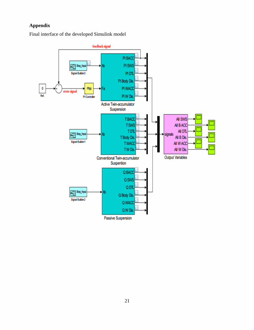
21
Appendix
Final interface of the developed Simulink model