Embed Size (px)
Citation preview
Piaggio would like to thank you
for choosing one of its products. We have prepared this manual to help you to get the very best from your vehicle. Please read it carefully before ridingthe vehicle for the first time. It contains information, tips and precautions for using your vehicle. It also describes features, details and devices to assureyou that you have made the right choice. We believe that if you follow our suggestions, you will soon get to know your new vehicle and it will serve youwell for a long time to come. This booklet forms an integral part of the vehicle; should the vehicle be sold, it must be transferred to the new owner.
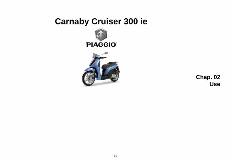
Carnaby Cruiser 300 ie
Ed. 2
The instructions given in this manual are intended to provide a clear, simple guide to using your vehicle; this booklet also details routine maintenanceprocedures and regular checks that should be carried out on the vehicle at an authorised Dealer or Service Centres. The booklet also containsinstructions for simple repairs. Any operations not specifically described in this booklet require the use of special tools and/or particular technicalknowledge: to carry out these operations, refer to any authorised Dealer or Service Centres.
2
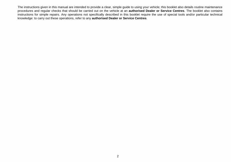
Personal safety
Failure to completely observe these instructions will result in serious risk of personalinjury.
Safeguarding the environment
Sections marked with this symbol indicate the correct use of the vehicle to prevent dam-aging the environment.
Vehicle intactness
The incomplete or non-observance of these regulations leads to the risk of seriousdamage to the vehicle and sometimes even the invalidity of the guarantee.
The signs that you see on this page are very important. They are used to highlight partsof the booklet that should be read with particular care. The different symbols are usedto make each topic in the manual simple and quick to locate.
3

4

INDEX
VEHICLE...................................................................................... 7Dashboard................................................................................ 9Analogue instrument panel....................................................... 10Indicator unir............................................................................. 12Key switch................................................................................. 13
Locking the steering wheel.................................................... 14Releasing the steering wheel................................................ 14
Switch direction indicators........................................................ 15Horn button............................................................................... 15Light switch............................................................................... 16Start-up button.......................................................................... 16Engine stop button.................................................................... 17
Keys...................................................................................... 17Immobilizer device enabled indicator led.............................. 18Operation............................................................................... 19Programming the immobilizer system................................... 20
Accessing the fuel tank............................................................. 21Opening the saddle............................................................... 22
Identification.............................................................................. 23Bag clip..................................................................................... 24
USE.............................................................................................. 27Checks...................................................................................... 28Refuelling.................................................................................. 28Tyre pressure............................................................................ 29Shock absorbers adjustment.................................................... 30Running in................................................................................. 31Starting up the engine............................................................... 32
Precautions........................................................................... 33Difficult start up......................................................................... 34Stopping the engine.................................................................. 34Stand......................................................................................... 35Automatic transmission............................................................. 35Safe driving............................................................................... 36
MAINTENANCE........................................................................... 39Engine oil level.......................................................................... 40
Engine oil level check............................................................ 40Engine oil top-up................................................................... 41Warning light (insufficient oil pressure)................................. 41Engine oil change.................................................................. 41
Hub oil level.............................................................................. 43Tyres......................................................................................... 44Spark plug dismantlement........................................................ 46Removing the air filter............................................................... 47Air filter cleaning....................................................................... 47Cooling fluid level...................................................................... 48Checking the brake oil level...................................................... 50
Braking system fluid top up................................................... 50Battery....................................................................................... 51
Use of a new battery............................................................. 52Long periods of inactivity.......................................................... 53Fuses........................................................................................ 54Front light group........................................................................ 59
Headlight adjustment............................................................. 61Front direction indicators........................................................... 62Rear optical unit........................................................................ 63Number plate light..................................................................... 66Rear-view mirrors...................................................................... 66Front and rear disc brake.......................................................... 67Puncture.................................................................................... 68Periods of inactivity................................................................... 69Cleaning the vehicle.................................................................. 69Troubleshooting........................................................................ 71
TECHNICAL DATA...................................................................... 75Toolkit....................................................................................... 80
SPARE PARTS AND ACCESSORIES........................................ 81Warnings................................................................................... 82
5

SCHEDULED MAINTENANCE.................................................... 85Scheduled servicing table......................................................... 86
6

Carnaby Cruiser 300 ie
Chap. 01Vehicle
7

01_01
8
1 Ve
hicl
e

Dashboard (01_01)
A = Bag hook
B = Horn button
C = Turn indicator switch
D = Rear brake lever
E = Light switch
F = Odometer and speedometer
G = Warning light unit
H = Rpm indicator and fuel gauge
I = RUN/OFF switch
L = Front brake lever
M = Throttle grip
N = Starter button
O = Ignition key switch
P= Passing button
9
1 Vehicle

01_02
Analogue instrument panel (01_02)
A= Trip odometer
10
1 Ve
hicl
e

B = Odometer reset knob
C = Speedometer
D = Odometer
E = Rpm indicator
F = Fuel gauge
11
1 Vehicle

01_03
Indicator unir (01_03)
A = Immobilizer LED
12
1 Ve
hicl
e
B = Injection telltale light
C = Coolant temperature warning light
D = Turn indicator warning light
E = High-beam warning light
F = Oil pressure warning light
G = Low fuel warning light
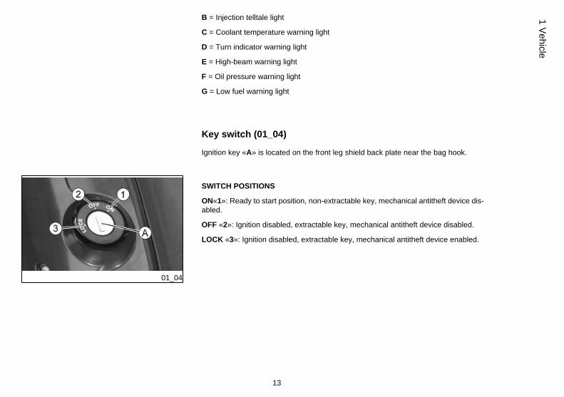
Key switch (01_04)
Ignition key «A» is located on the front leg shield back plate near the bag hook.
01_04
SWITCH POSITIONS
ON«1»: Ready to start position, non-extractable key, mechanical antitheft device dis-abled.
OFF «2»: Ignition disabled, extractable key, mechanical antitheft device disabled.
LOCK «3»: Ignition disabled, extractable key, mechanical antitheft device enabled.
13
1 Vehicle
01_05
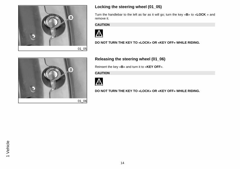
Locking the steering wheel (01_05)
Turn the handlebar to the left as far as it will go; turn the key «B» to «LOCK » andremove it.
CAUTION
DO NOT TURN THE KEY TO «LOCK» OR «KEY OFF» WHILE RIDING.
01_06
Releasing the steering wheel (01_06)
Reinsert the key «B» and turn it to «KEY OFF».
CAUTION
DO NOT TURN THE KEY TO «LOCK» OR «KEY OFF» WHILE RIDING.
14
1 Ve
hicl
e
01_07
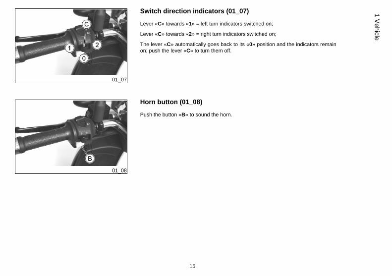
Switch direction indicators (01_07)
Lever «C» towards «1» = left turn indicators switched on;
Lever «C» towards «2» = right turn indicators switched on;
The lever «C» automatically goes back to its «0» position and the indicators remainon; push the lever «C» to turn them off.
01_08
Horn button (01_08)
Push the button «B» to sound the horn.
15
1 Vehicle
01_09
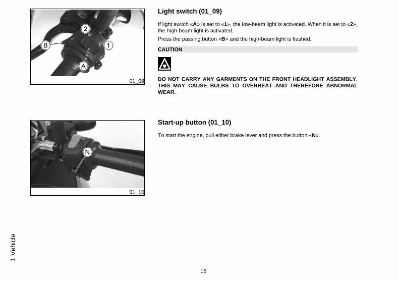
Light switch (01_09)
If light switch «A» is set to «1», the low-beam light is activated. When it is set to «2»,the high-beam light is activated.Press the passing button «B» and the high-beam light is flashed.
CAUTION
DO NOT CARRY ANY GARMENTS ON THE FRONT HEADLIGHT ASSEMBLY.THIS MAY CAUSE BULBS TO OVERHEAT AND THEREFORE ABNORMALWEAR.
01_10
Start-up button (01_10)
To start the engine, pull either brake lever and press the button «N».
16
1 Ve
hicl
e
01_11
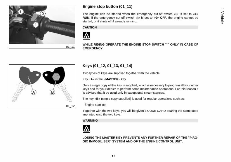
Engine stop button (01_11)
The engine can be started when the emergency cut-off switch «I» is set to «1»RUN; if the emergency cut-off switch «I» is set to «0» OFF, the engine cannot bestarted, or it shuts off if already running.
CAUTION
WHILE RIDING OPERATE THE ENGINE STOP SWITCH "I" ONLY IN CASE OFEMERGENCY.
01_12
Keys (01_12, 01_13, 01_14)
Two types of keys are supplied together with the vehicle.
Key «A» is the «MASTER» key.
Only a single copy of this key is supplied, which is necessary to program all your otherkeys and for your dealer to perform some maintenance operations. For this reason itis advised that it be used only in exceptional circumstances.
The key «B» (single copy supplied) is used for regular operations such as:
- Engine start-up.
Together with the two keys, you will be given a CODE CARD bearing the same codeimprinted onto the two keys.
WARNING
LOSING THE MASTER KEY PREVENTS ANY FURTHER REPAIR OF THE "PIAG-GIO IMMOBILISER" SYSTEM AND OF THE ENGINE CONTROL UNIT.
17
1 Vehicle

01_13
01_14
WARNING
KEEP THE "CODE CARD" AND THE MASTER KEY IN A SAFE PLACE (NOT INTHE VEHICLE).
01_15
Immobilizer device enabled indicator led (01_15)
The activation of the «PIAGGIO IMMOBILISER» system is signalled by the a flashingindicator «A».
In order to reduce battery discharge, the indicator LED turns off automatically after 48hours of uninterrupted functioning.
Should the system fail, different LED flashing patterns will provide the AuthorisedService Centre with information on the type of fault detected.
18
1 Ve
hicl
e

Operation
Each time the ignition key «B» is removed while in the «OFF» or «LOCK» positions,the protection system activates the engine lock. Turning the ignition key «B» to«ON» disables the engine lock, provided that the safety system recognises the codetransmitted by the key. If the code is not recognised, turn the ignition key «B» first to«OFF» and then back to «ON» again; if lock persists, try again using the «A» MASTERkey. If the engine cannot be started, contact an Authorised Service Centre, whichis provided with the electronic equipment required to detect and repair the system.
When the supplementary starter keys are required, remember that the all the keys,whether new or existing, should be programmed.
Contact an Authorised Service Centre and bring the «A» MASTER key and all«B» starter keys that you own.
The codes of starter keys not submitted for the new programming procedure are de-leted from the memory. Any lost starter keys will therefore not be enabled to start theengine.
WARNING
EACH KEY HAS ITS OWN AND UNIQUE CODE, WHICH MUST BE STORED INTHE SYSTEM CONTROL UNIT MEMORY.
VIOLENT SHOCKS MAY AFFECT THE ELECTRONIC COMPONENTS OF THEKEY.
IF THE VEHICLE IS SOLD, THE MASTER-HANDGRIP KEY (AS WELL AS THEOTHER STARTER KEYS) AND THE «CODE CARD» MUST ALSO BE TRANS-FERRED TO THE NEW OWNER.
19
1 Vehicle
01_16
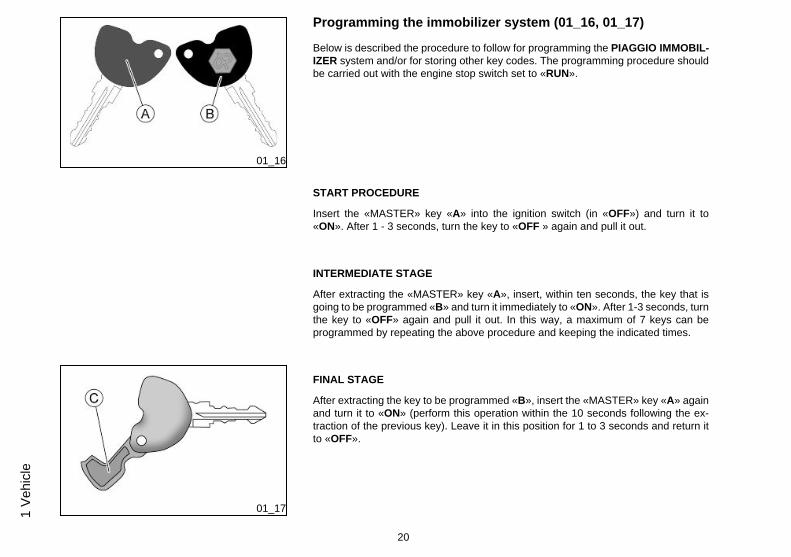
Programming the immobilizer system (01_16, 01_17)
Below is described the procedure to follow for programming the PIAGGIO IMMOBIL-IZER system and/or for storing other key codes. The programming procedure shouldbe carried out with the engine stop switch set to «RUN».
START PROCEDURE
Insert the «MASTER» key «A» into the ignition switch (in «OFF») and turn it to«ON». After 1 - 3 seconds, turn the key to «OFF » again and pull it out.
INTERMEDIATE STAGE
After extracting the «MASTER» key «A», insert, within ten seconds, the key that isgoing to be programmed «B» and turn it immediately to «ON». After 1-3 seconds, turnthe key to «OFF» again and pull it out. In this way, a maximum of 7 keys can beprogrammed by repeating the above procedure and keeping the indicated times.
01_17
FINAL STAGE
After extracting the key to be programmed «B», insert the «MASTER» key «A» againand turn it to «ON» (perform this operation within the 10 seconds following the ex-traction of the previous key). Leave it in this position for 1 to 3 seconds and return itto «OFF».
20
1 Ve
hicl
e

CORRECT PROGRAMMING CHECK PHASE
Insert the «MASTER» key «A» disabling the transponder «C» (i.e., by tilting the keycap by 90°), and turn the key to «ON». Perform the engine starter operation. Ensurethat the engine does not start. Insert the programmed key «B» and repeat the starteroperation. Check that engine starts.
WARNING
SHOULD YOU START THE ENGINE WITH THE MASTER KEY (WITH TRANS-PONDER OFF) OR IN THE EVENT OF WRONG OPERATION DURING PROGRAM-MING, REPEAT THE PROCEDURE FROM THE BEGINNING.
01_18
Accessing the fuel tank (01_18, 01_19)
Insert the key into the switch and press it down until the saddle opens; then lift thesaddle. In the event that the key switch is in «LOCK», turn the key to «OFF» or«ON» before pressing down.
21
1 Vehicle
01_19
01_20
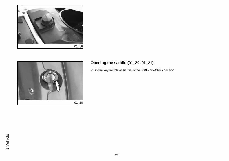
Opening the saddle (01_20, 01_21)
Push the key switch when it is in the «ON» or «OFF» position.
22
1 Ve
hicl
e

01_21
Identification (01_22, 01_23)
Identification registration numbers are made up of a prefix and a number, stamped onthe chassis and on the engine. These numbers must always be quoted when orderingspare parts. We recommend checking that the chassis registration number stampedon the vehicle corresponds with that on the vehicle documentation.
CAUTION
BE REMINDED THAT ALTERING IDENTIFICATION REGISTRATION NUMBERSCAN LEAD TO SERIOUS PENAL SANCTIONS (IMPOUNDING OF THE VEHICLE,ETC.).
23
1 Vehicle
01_22
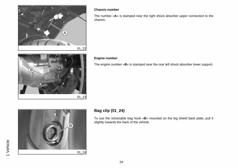
Chassis number
The number «A» is stamped near the right shock absorber upper connection to thechassis.
01_23
Engine number
The engine number «B» is stamped near the rear left shock absorber lower support.
01_24
Bag clip (01_24)
To use the retractable bag hook «B» mounted on the leg shield back plate, pull itslightly towards the back of the vehicle.
24
1 Ve
hicl
e

25
1 Vehicle

26
1 Ve
hicl
e
Carnaby Cruiser 300 ie
Chap. 02Use
27

Checks
Before using the vehicle, check:
1. That the fuel tank is full.
2. The front and rear brake fluid level.
3. That the tyres are properly inflated.
4. The correct functioning of side lights, headlamp, turn indicators, stop light and li-cense plate light.
5. The correct functioning of front and rear brakes.
6.The oil level in the gearcase.
7. The engine oil level.
8.The coolant level.
02_01
Refuelling (02_01)
Reach the fuel tank and unscrew the cap «A».
Use premium unleaded petrol, with minimum octane rating of 95.
A specific gauge on the instrument panel indicates the fuel level.
WARNING
SWITCH OFF THE ENGINE BEFORE REFUELLING WITH PETROL.
PETROL IS HIGHLY INFLAMMABLE.
DO NOT SMOKE AND KEEP NAKED FLAMES AT A DISTANCE:FIRE HAZARD.
28
2 U
se

DO NOT INHALE FUEL FUMES.
DO NOT ALLOW PETROL TO COME INTO CONTACT WITH HOT ENGINE ORANY PLASTIC PARTS.
CAUTION
PETROL DAMAGES THE PLASTIC PARTS OF THE BODYWORK.
02_02
Tyre pressure (02_02)
Check tyre pressure and wear periodically (roughly every 500 km). Tyres feature wearindicators; replace tyres as soon as these indicators become visible on the tyre tread.Also check that the tyres do not show signs of splitting at the sides or irregular treadwear; if this occurs go to an authorised workshop or at least to a workshop equippedto replace tyres.
CAUTION
TYRE PRESSURE SHOULD BE CHECKED WHEN TYRES ARE COLD.INCOR-RECT TYRE PRESSURE CAUSES ABNORMAL TYRE WEAR AND MAKES RID-ING DANGEROUS.
TYRES MUST BE REPLACED WHEN THE TREAD REACHES THE WEAR LIMITSSET FORTH BY LAW.
29
2 Use

TYRE INFLATION PRESSUREFront tyre pressure (withpassenger)
2 bar (-)
Rear tyre pressure (withpassenger)
2.3 bar (-)
TYRESFront tyre Tubeless, 110/70 - 16'' 52P
Rear tyre 130/70- 16'' 61P Tubeless
02_03
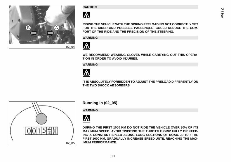
Shock absorbers adjustment (02_03, 02_04)
The preloading of the springs can be adjusted to 4 positions acting on the ring nutlocated in the lower part of the shock absorbers with the specific spanner supplied.
Position 1: minimum preload: rider only
Position 2 medium preloading: rider only
Position 3 medium preloading: rider and passenger
Position 4: maximum preloading: rider, passenger, and luggage.
In order to carry out this operation you will need to use the specific spanner in the kit.Spring preloading increases by turning the ring nut towards «A», but decreases if thering nut is turned towards «B».
30
2 U
se
02_04
CAUTION
RIDING THE VEHICLE WITH THE SPRING PRELOADING NOT CORRECTLY SETFOR THE RIDER AND POSSIBLE PASSENGER, COULD REDUCE THE COM-FORT OF THE RIDE AND THE PRECISION OF THE STEERING.
WARNING
WE RECOMMEND WEARING GLOVES WHILE CARRYING OUT THIS OPERA-TION IN ORDER TO AVOID INJURIES.
WARNING
IT IS ABSOLUTELY FORBIDDEN TO ADJUST THE PRELOAD DIFFERENTLY ONTHE TWO SHOCK ABSORBERS
02_05
Running in (02_05)
WARNING
DURING THE FIRST 1000 KM DO NOT RIDE THE VEHICLE OVER 80% OF ITSMAXIMUM SPEED. AVOID TWISTING THE THROTTLE GRIP FULLY OR KEEP-ING A CONSTANT SPEED ALONG LONG SECTIONS OF ROAD. AFTER THEFIRST 1000 KM, GRADUALLY INCREASE SPEED UNTIL REACHING THE MAX-IMUM PERFORMANCE.
31
2 Use

02_06
02_07
02_08
Starting up the engine (02_06, 02_07, 02_08)
The vehicle is supplied with an ignition cut-off system, activated by the emergencycut-off switch. The engine cannot be started if the ignition cut-off switch is in theOFF position.
A running engine automatically shuts off when the ignition cut-off switch is set toOFF.
The vehicle is equipped with automatic transmission with direct drive, so that startingis effected by turning the throttle grip to idle speed; to start-off from a stationary posi-tion, progressively twist the throttle grip. The vehicle is equipped with an electrical fuelpump that switches on automatically as soon as the engine is started.
In order to start the vehicle:
1. Rest the vehicle on its centre stand, ensuring the rear wheel is not touching theground.
2. Keep the throttle grip «A» completely untwisted.
3. Insert the key into the ignition switch «B» and turn it to ON.
4. Make sure that switch «C» is set to RUN.
5. Pull either the front «D» or the rear «E» brake lever, then press the starter button«F».
WARNING
THE AUTOMATIC TRANSMISSION MAKES THE REAR WHEEL TURN EVENWHEN THE THROTTLE GRIP IS SLIGHTLY TWISTED. RELEASE THE BRAKECAREFULLY AFTER STARTING, AND THEN ACCELERATE GRADUALLY.
32
2 U
se

CAUTION
DO NOT START-UP THE ENGINE IN CLOSED AREAS BECAUSE EXHAUSTGASES ARE TOXIC.
CAUTION
DUE TO THE HIGH TEMPERATURES THE CATALYTIC CONVERTER CANREACH, ALWAYS TAKE CARE, WHEN PARKING THE VEHICLE, THAT THE EX-HAUST DOES NOT COME INTO CONTACT WITH FLAMMABLE MATERIALS, TOAVOID SERIOUS BURNS.
CAUTION
DO NOT SHUT OFF THE ENGINE WHILE THE VEHICLE IS MOVING. UNBURNEDFUEL COULD ENTER THE CATALYTIC CONVERTER AND BURN, CAUSING THECONVERTER TO OVERHEAT AND POSSIBLY DESTROYING IT.
Precautions
WARNING
NEVER STRESS THE ENGINE AT LOW TEMPERATURES IN ORDER TO AVOIDPOSSIBLE DAMAGE. BE CAREFUL NEVER TO EXCEED THE MAXIMUM SPEEDWHILE RUNNING DOWNHILL, IN ORDER TO AVOID DAMAGING THE ENGINE.IN ANY CASE, IN ORDER TO PRESERVE THE ENGINE FROM PROLONGEDOVERREVVING, THE REVOLUTION LIMITER WILL BE ACTIVATED IF THE EN-GINE SPEED EXCEEDS THE ESTABLISHED THRESHOLD. DO NOT ACTIVATE
33
2 Use
THE REVOLUTION LIMITER RECURRENTLY SO AS TO AVOID DAMAGING THECATALYTIC CONVERTER.
WARNING
AFTER A LONG DISTANCE COVERED AT THE MAXIMUM SPEED, DO NOT STOPTHE ENGINE IMMEDIATELY, BUT LET IT RUN AT IDLE FOR A FEW SECONDS.
Difficult start up
In the rare case of a flooded engine, and in order to facilitate starting, try putting thevehicle into motion with the throttle slightly open. It is however necessary, once theengine is started, to take your vehicle to an Authorised Service Centre to determinethe cause of this problem and to re-establish the vehicle proper functioning.
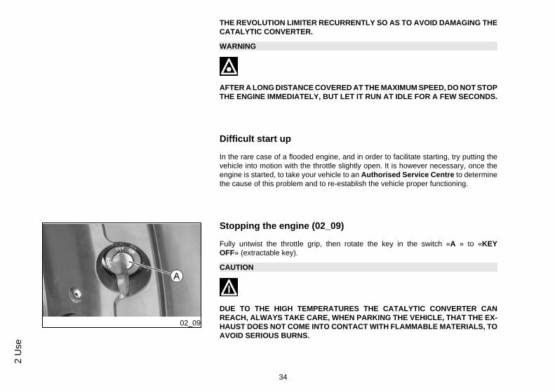
02_09
Stopping the engine (02_09)
Fully untwist the throttle grip, then rotate the key in the switch «A » to «KEYOFF» (extractable key).
CAUTION
DUE TO THE HIGH TEMPERATURES THE CATALYTIC CONVERTER CANREACH, ALWAYS TAKE CARE, WHEN PARKING THE VEHICLE, THAT THE EX-HAUST DOES NOT COME INTO CONTACT WITH FLAMMABLE MATERIALS, TOAVOID SERIOUS BURNS.
34
2 U
se
CAUTION
DO NOT SHUT OFF THE ENGINE WHILE THE VEHICLE IS MOVING. UNBURNEDFUEL COULD ENTER THE CATALYTIC CONVERTER AND BURN, CAUSING THECONVERTER TO OVERHEAT AND POSSIBLY DESTROYING IT.
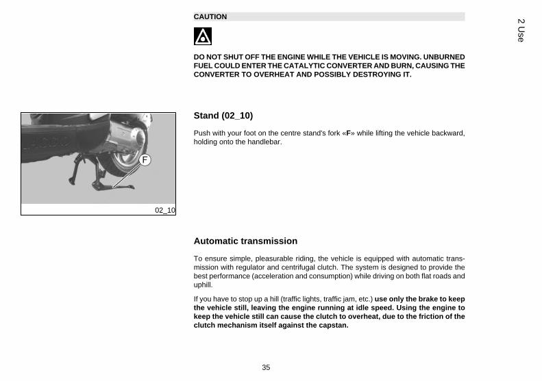
02_10
Stand (02_10)
Push with your foot on the centre stand's fork «F» while lifting the vehicle backward,holding onto the handlebar.
Automatic transmission
To ensure simple, pleasurable riding, the vehicle is equipped with automatic trans-mission with regulator and centrifugal clutch. The system is designed to provide thebest performance (acceleration and consumption) while driving on both flat roads anduphill.
If you have to stop up a hill (traffic lights, traffic jam, etc.) use only the brake to keepthe vehicle still, leaving the engine running at idle speed. Using the engine tokeep the vehicle still can cause the clutch to overheat, due to the friction of theclutch mechanism itself against the capstan.
35
2 Use

It is therefore recommended to avoid conditions of prolonged clutch slippage (otherthan those previously indicated) like driving uphill fully laden on steep slopes or startingoff with driver and passenger at slopes greater than 25%.
Take the following precautions if the clutch overheats:
1. Do not continue riding in such conditions.
2. Let the clutch cool down with the engine at idle speed for a few minutes.
02_11
Safe driving (02_11)
Some simple tips are provided below that will enable you to use your vehicle on a dailybasis, confidently and safely. Your skill and your mechanical knowledge are the basisof safe riding. We recommend trying out the vehicle in traffic-free zones in order toacquire a good knowledge of the vehicle it self.1. Before riding off, remember to put on the helmet and fasten it correctly.
2. Reduce speed on rough roads and ride with care.
3. After riding on a long stretch of wet road without using the brakes, braking can bepoor at the beginning. In these conditions, it is a good idea to apply the brakes fromtime to time.
4. Do not brake hard on wet, unsurfaced or slippery roads.
5. Avoid riding off by mounting the scooter when it is resting on its support. In anycase, in order to avoid abrupt departures, the rear wheel should not be turning whenin comes into contact with the ground.
6. If the vehicle is used on roads covered with sand, mud, snow mixed with salt, etc.,clean the brake disc frequently with a mild detergent in order to prevent abrasive par-ticles from building up inside the holes, which can result in early brake pad wear.
36
2 U
se

CAUTION
ALWAYS RIDE WITHIN YOUR LIMITS RIDING UNDER THE INFLUENCE OF AL-COHOL OR OTHER DRUGS AND CERTAIN MEDICINES IS EXTREMELY DAN-GEROUS.
CAUTION
ANY ELABORATION THAT MODIFIES THE VEHICLE'S PERFORMANCES, SUCHAS TAMPERING WITH ORIGINAL STRUCTURAL PARTS IS STRICTLY FORBID-DEN BY LAW, AND RENDERS THE VEHICLE NO LONGER CONFORMING TOTHE APPROVED TYPE AND DANGEROUS FOR RIDING.
CAUTION
DO NOT ADJUST THE MIRRORS WHILE RIDING. THIS COULD CAUSE YOU TOLOOSE CONTROL OF THE VEHICLE.
WARNING
IN ORDER TO PREVENT ANY ACCIDENTS RIDE VERY CAREFULLY AFTERADDING ACCESSORIES AND WHILE CARRYING LUGGAGE. THE ADDITION OFACCESSORIES AND LUGGAGE CAN REDUCE YOUR SCOOTER STABILITYAND PERFORMANCE, AS WELL AS THE LEVEL OF SAFETY DURING USE.NEVER DRIVE THE SCOOTER EQUIPPED WITH ACCESSORIES AT A SPEEDHIGHER THAN 100 km/h (see section "SPARE PARTS AND ACCESSORIES").
37
2 Use

38
2 U
se

Carnaby Cruiser 300 ie
Chap. 03Maintenance
39
Engine oil level
In 4T engines, the engine oil is used to lubricate the distribution elements, the benchbearings and the thermal group. An insufficient quantity of oil can cause seriousdamage to the engine. In all four-stroke engines, a loss of efficiency in oil perform-ance and consumption should be considered normal. Consumption can particularlyreflect the conditions of use (i.e. when driving at 'full acceleration' all the time, oil con-sumption increases). In order to prevent any problems, we recommend checkingthe oil level any time you use the vehicle. The scooter is, however, equippedwith an oil pressure warning light on the instrument panel.
03_01
03_02
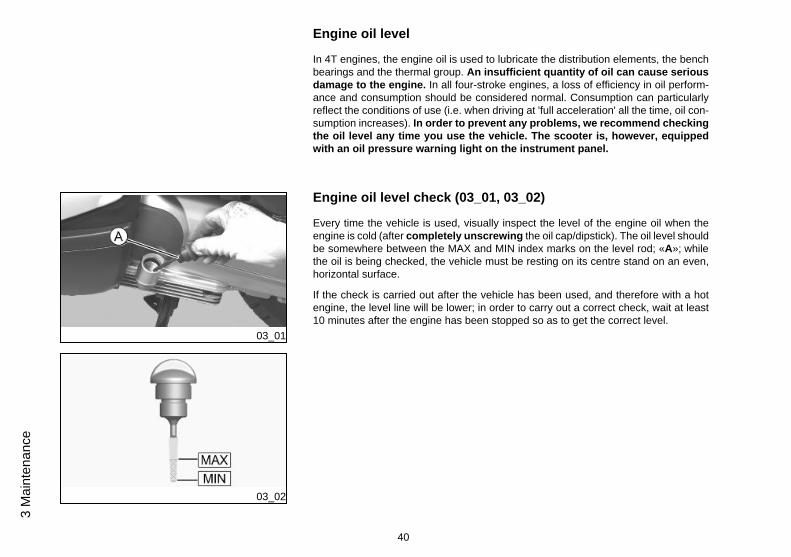
Engine oil level check (03_01, 03_02)
Every time the vehicle is used, visually inspect the level of the engine oil when theengine is cold (after completely unscrewing the oil cap/dipstick). The oil level shouldbe somewhere between the MAX and MIN index marks on the level rod; «A»; whilethe oil is being checked, the vehicle must be resting on its centre stand on an even,horizontal surface.
If the check is carried out after the vehicle has been used, and therefore with a hotengine, the level line will be lower; in order to carry out a correct check, wait at least10 minutes after the engine has been stopped so as to get the correct level.
40
3 M
aint
enan
ce
Engine oil top-up
The oil should be topped up after having checked the level and in any case by addingoil without ever exceeding the MAX. level. The topping up of the level between theMIN and MAX implies a quantity of 400 cm³ of oil. As reported in the scheduled main-tenance table, it is still expected to perform, at an Authorised Service Centre, a checkand engine oil top-up.
03_03
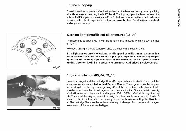
Warning light (insufficient oil pressure) (03_03)
The scooter is equipped with a warning light «F» that lights up when the key is turnedto «ON».
However, this light should switch off once the engine has been started.
If the light comes on while braking, at idle speed or while turning a corner, it isnecessary to check the oil level and top it up if required. If after having toppedup the oil, the warning light still turns on while braking, at idle speed or whileturning a corner, it will be necessary to turn to an Authorised Service Centre.
03_04
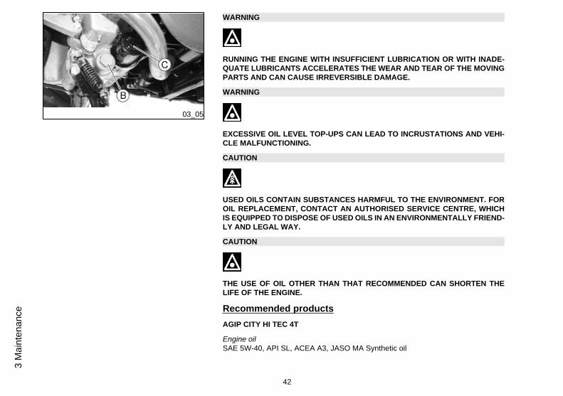
Engine oil change (03_04, 03_05)
Have oil changed and the cartridge filter «C» replaced as indicated in the scheduledmaintenance table at an Authorised Service Centre. The engine should be emptiedby draining the oil through drainage plug «B » of the mesh filter on the flywheel side.In order to facilitate the oil drainage, loosen the cap/dipstick. Since a certain quantityof oil still remains in the circuit, add approx. 950 ÷ 1000 cm³ of oil through the cap«A. Then start the engine, leave it running for a few minutes and shut it off: after 5minutes, check the level and if necessary, top-up without exceeding the MAX lev-el. The cartridge filter must be replaced at every oil change. For top-ups and changes,use new oil of the recommended type.
41
3 Maintenance
03_05
WARNING
RUNNING THE ENGINE WITH INSUFFICIENT LUBRICATION OR WITH INADE-QUATE LUBRICANTS ACCELERATES THE WEAR AND TEAR OF THE MOVINGPARTS AND CAN CAUSE IRREVERSIBLE DAMAGE.
WARNING
EXCESSIVE OIL LEVEL TOP-UPS CAN LEAD TO INCRUSTATIONS AND VEHI-CLE MALFUNCTIONING.
CAUTION
USED OILS CONTAIN SUBSTANCES HARMFUL TO THE ENVIRONMENT. FOROIL REPLACEMENT, CONTACT AN AUTHORISED SERVICE CENTRE, WHICHIS EQUIPPED TO DISPOSE OF USED OILS IN AN ENVIRONMENTALLY FRIEND-LY AND LEGAL WAY.
CAUTION
THE USE OF OIL OTHER THAN THAT RECOMMENDED CAN SHORTEN THELIFE OF THE ENGINE.
Recommended productsAGIP CITY HI TEC 4T
Engine oilSAE 5W-40, API SL, ACEA A3, JASO MA Synthetic oil
42
3 M
aint
enan
ce
03_06
03_07
Hub oil level (03_06, 03_07)
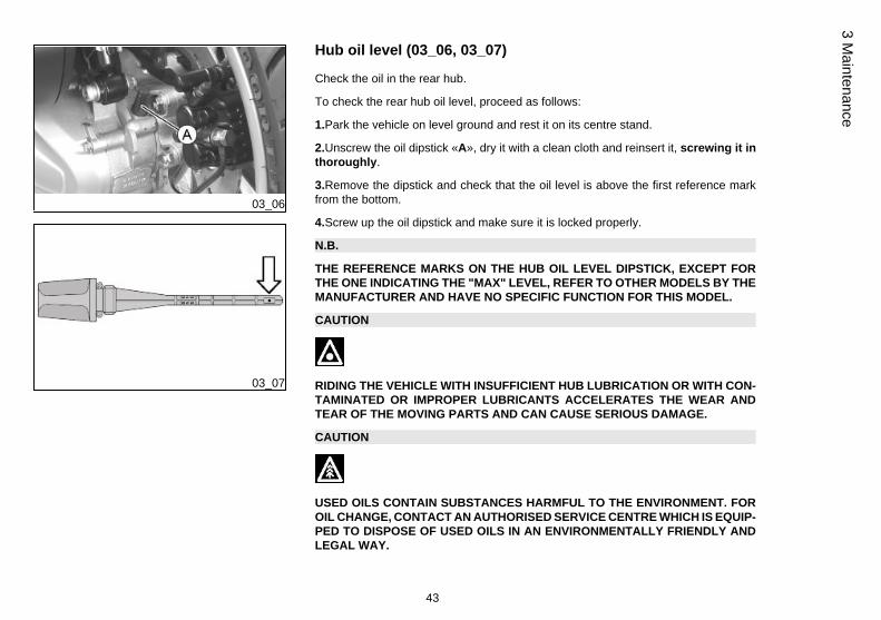
Check the oil in the rear hub.
To check the rear hub oil level, proceed as follows:
1.Park the vehicle on level ground and rest it on its centre stand.
2.Unscrew the oil dipstick «A», dry it with a clean cloth and reinsert it, screwing it inthoroughly.
3.Remove the dipstick and check that the oil level is above the first reference markfrom the bottom.
4.Screw up the oil dipstick and make sure it is locked properly.
N.B.
THE REFERENCE MARKS ON THE HUB OIL LEVEL DIPSTICK, EXCEPT FORTHE ONE INDICATING THE "MAX" LEVEL, REFER TO OTHER MODELS BY THEMANUFACTURER AND HAVE NO SPECIFIC FUNCTION FOR THIS MODEL.
CAUTION
RIDING THE VEHICLE WITH INSUFFICIENT HUB LUBRICATION OR WITH CON-TAMINATED OR IMPROPER LUBRICANTS ACCELERATES THE WEAR ANDTEAR OF THE MOVING PARTS AND CAN CAUSE SERIOUS DAMAGE.
CAUTION
USED OILS CONTAIN SUBSTANCES HARMFUL TO THE ENVIRONMENT. FOROIL CHANGE, CONTACT AN AUTHORISED SERVICE CENTRE WHICH IS EQUIP-PED TO DISPOSE OF USED OILS IN AN ENVIRONMENTALLY FRIENDLY ANDLEGAL WAY.
43
3 Maintenance

CAUTION
UPON REPLACING HUB OIL, AVOID THE OIL COMING INTO CONTACT WITHTHE REAR BRAKE DISC.
Recommended productsAGIP ROTRA 80W-90
Rear hub oilSAE 80W/90 Oil that exceeds the requirements of API GL3 specifications
CharacteristicTransmission oil
250 cm³
03_08
Tyres (03_08)
Check tyre pressure and wear periodically (roughly every 500 km). Tyres feature wearindicators; replace tyres as soon as these indicators become visible on the tyre tread.Also check that the tyres do not show signs of splitting at the sides or irregular treadwear; if this occurs go to an authorised workshop or at least to a workshop equippedto replace tyres.
CAUTION
TYRE PRESSURE SHOULD BE CHECKED WHEN TYRES ARE COLD.INCOR-RECT TYRE PRESSURE CAUSES ABNORMAL TYRE WEAR AND MAKES RID-ING DANGEROUS.
44
3 M
aint
enan
ce
TYRES MUST BE REPLACED WHEN THE TREAD REACHES THE WEAR LIMITSSET FORTH BY LAW.
WARNING
THE WHEELS FITTED WITH TYRES SHOULD ALWAYS BE BALANCED. RIDINGTHE VEHICLE WITH VERY LOW TYRE PRESSURE OR WITH INCORRECTLYBALANCED TYRES CAN LEAD TO DANGEROUS STEERING VIBRATIONS.
TYRESFront tyre Tubeless, 110/70 - 16'' 52P
Rear tyre 130/70- 16'' 61P Tubeless
TYRE INFLATION PRESSUREFront tyre pressure (withpassenger)
2 bar (-)
Rear tyre pressure (withpassenger)
2.3 bar (-)
45
3 Maintenance

03_09
03_10
03_11
Spark plug dismantlement (03_09, 03_10, 03_11)
To remove the spark plug, proceed as follows:
1. Lift the saddle.
2. Working from both sides, undo the screw indicated.
3. Pull up and lift the cover until you can see the two screws «A» and undo them.
4. Remove the spark plug inspection lid «B».
5. Disconnect the HV cable cap «C» from the spark plug.
6. Unscrew the spark plug using the wrench supplied.
When refitting, place the spark plug into the hole at the required angle and fingertighten it as far as it will go. Use the wrench only to tighten it. Once the spark plug istightened, insert the cap «C» on the spark plug.Refit the covers.
N.B.
USE OF SPARK PLUGS OTHER THAN THE INDICATED TYPE OR UNSHIELDEDSPARK PLUG CAPS CAN LEAD TO FAULTS IN THE VEHICLE 'S ELECTRICALSYSTEM.
WARNING
THE SPARK PLUG MUST BE REMOVED WHEN THE ENGINE IS COLD. CHECKTHE SPARK PLUG AS INDICATED IN THE SCHEDULED MAINTENANCE TABLE.USING NON-COMPLYING ELECTRONIC CENTRAL UNITS AND ELECTRONICIGNITIONS OR SPARK PLUGS OTHER THAN THOSE PRESCRIBED MAY SERI-OUSLY DAMAGE THE ENGINE. IF THE SPARK PLUG IS REMOVED AFTER THEENGINE HAS FLOODED, IT IS RECOMMENDED TO KEEP THE TUBE CONNEC-TED TO THE SPARK PLUG AND THE SPARK PLUG IN CONTACT WITH AGROUND CONNECTION FAR FROM THAT SPARK PLUG HOLE IN ORDER TOPREVENT EXPELLED FUEL FROM CATCHING FIRE.
46
3 M
aint
enan
ce
CharacteristicSpark plug
NGK CR8EKB
Electrode gap
0.7 to 0.8 mm
03_12
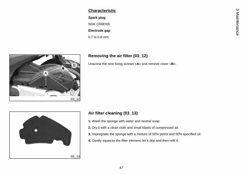
Removing the air filter (03_12)
Unscrew the nine fixing screws «A» and remove cover «B».
03_13
Air filter cleaning (03_13)
1. Wash the sponge with water and neutral soap.
2. Dry it with a clean cloth and small blasts of compressed air.
3. Impregnate the sponge with a mixture of 50% petrol and 50% specified oil.
4. Gently squeeze the filter element, let it drip and then refit it.
47
3 Maintenance

CAUTION
IF THE VEHICLE IS USED ON DUSTY ROADS IT IS NECESSARY TO CARRY OUTMAINTENANCE CHECKS OF THE AIR FILTER MORE OFTEN TO AVOID DAM-AGING THE ENGINE.
Recommended productsAGIP FILTER OIL
Oil for air filter spongeMineral oil with specific additives for increased adhesiveness
03_14
Cooling fluid level (03_14, 03_15, 03_16, 03_17)
Engine cooling is carried out by a forced-circulation coolant system. The coolant con-sists of a mixture 50% de-ionised water and 50% glycol ethylene-based antifreezesolution with corrosion inhibitors.
The coolant supplied with the scooter is already mixed and ready for use.
If the coolant temperature warning light comes on during regular vehicle functioning,shut off the engine, let it cool off and check coolant level; if the level is OK, contact anAuthorised Service Centre.
Check coolant when the engine is cold as indicated in the scheduled maintenancetables, following the steps below.
1. Place the scooter upright on its stand and turn the handlebar to the right: removethe cover by undoing screw «A».
2. Remove the expansion tank cover «B» by turning it anticlockwise.
3. Look inside the expansion tank and check that the reference tongue «C» is covered.
4. Fill up the expansion tank if the coolant level does not reach the reference tongue«C».
48
3 M
aint
enan
ce

03_15
03_16
03_17
If the level is not correct, proceed to top-up when the engine is cold. If the coolantneeds to be topped up frequently or the expansion tank is completely dry, check thecooling system to find the cause of the problem. It is therefore essential to have thecooling system checked at an Authorised Service Centre.
Replace coolant as indicated in the scheduled maintenance table. Take your vehicleto an Authorised Service Centre for this operation.
WARNING
TO AVOID THE RISK OF SCALDING, DO NOT UNSCREW THE EXPANSIONTANK COVER WHILE THE ENGINE IS STILL HOT.
WARNING
IN ORDER TO AVOID HARMFUL FLUID LEAKS WHILE RIDING, IT IS IMPORTANTTO MAKE SURE THAT THE LEVEL DOES NOT EXCEED THE REFERENCETONGUE TOO MUCH.
TO ENSURE CORRECT ENGINE OPERATION, KEEP THE RADIATOR GRILLECLEAN.
Recommended productsAGIP PERMANENT SPECIAL
coolantMonoethylene glycol-based antifreeze fluid, CUNA NC 956-16
49
3 Maintenance

03_18
Checking the brake oil level (03_18)
The brake fluid reservoirs for front and rear brakes are located on the brake pumpsfixed on the handlebar. To check fluid level, proceed as follows:
1. Rest the vehicle onto its centre stand, with the handlebar centred.
2. Check fluid level through the specific sight glass «A».
A drop in brake fuel level may be caused by pad wear. Should the level appear to bebelow the minimum mark, please contact an Authorised Service Centre or Dealerin order to have a thorough inspection of the braking system carried out.
03_19
Braking system fluid top up (03_19)
Proceed as follows:
1. Rest the vehicle onto its centre stand, with the handlebar centred.
2. Remove the reservoir cover «A» by undoing the two screws «B»; restore fluid levelby adding recommended fluid type only, and without exceeding the maximum level.
Under standard climatic conditions, replace fluid as indicated in the scheduled main-tenance table.
This operation must be carried out by trained personnel; take your vehicle to an au-thorised Service centre or Dealer.
WARNING
BRAKE CIRCUIT FLUID IS VERY CORROSIVE; DO NOT LET IT COME INTOCONTACT WITH PAINTED PARTS.
CAUTION
ONLY USE DOT 4-CLASSIFIED BRAKE FLUID.
WARNING
THE BRAKE FLUID IS HAZARDOUS: IN CASE OF ACCIDENTAL CONTACT,WASH OFF WITH WATER.
50
3 M
aint
enan
ce
WARNING
THE BRAKING CIRCUIT LIQUID IS HYGROSCOPIC, AND ABSORBS THE HU-MIDITY OF SURROUNDING AIR. IF THE HUMIDITY IN THE BRAKING FLUIDEXCEEDS A CERTAIN VALUE, IT WILL LEAD TO INEFFICIENT BRAKING. NEV-ER USE BRAKING FLUID KEPT IN CONTAINERS THAT HAVE ALREADY BEENOPENED, OR PARTIALLY USED.
Recommended productsAGIP BRAKE 4
Brake fluidFMVSS DOT 4 Synthetic fluid
03_20
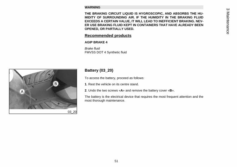
Battery (03_20)
To access the battery, proceed as follows:
1. Rest the vehicle on its centre stand.
2. Undo the two screws «A» and remove the battery cover «B».
The battery is the electrical device that requires the most frequent attention and themost thorough maintenance.
51
3 Maintenance

03_21
03_22
Use of a new battery (03_21, 03_22)
To install a new battery:1. Rest the vehicle on its centre stand.
2. Undo the two screws «A» and remove the battery cover «B».
3. Place the battery in its housing.
4. Connect the positive pole «+» first and then the negative pole «-».
5. Fit the battery cover.
CAUTION
DO NOT REVERSE THE POLARITY: RISK OF SHORT CIRCUIT AND DAMAGETO THE ELECTRICAL SYSTEM.
WARNING
DO NOT DISCONNECT THE BATTERY CABLES WITH THE ENGINE RUNNING,THIS CAN CAUSE IRREPARABLE DAMAGE TO THE VEHICLE'S ELECTRONICCONTROL UNIT.
WARNING
USED BATTERIES ARE HARMFUL FOR THE ENVIRONMENT. COLLECTIONAND DISPOSAL SHOULD BE CARRIED OUT IN COMPLIANCE WITH REGULA-TIONS IN FORCE.
CharacteristicBattery
52
3 M
aint
enan
ce

Sealed, 12 V / 10 Ah
Long periods of inactivity
Battery performance will decrease if the vehicle is not used for a long time. This is theresult of the natural phenomenon of battery discharging plus residual absorption byvehicle components with constant power consumption. Poor battery performance mayalso be due to environmental conditions and the cleanliness of the poles. In order toavoid difficult starts and/or irreversible damage to the battery, follow any of thesesteps:
- At least once a month start the engine and run it slightly above idle speed for 10-15minutes. This keeps all the engine components, as well as the battery, in good workingorder.
- Take your vehicle to a garage (as indicated in the «Vehicle not used for extendedperiods» section) to have the battery removed. Have the battery cleaned, chargedfully and stored in a dry, ventilated place. Recharge at least once every twomonths.
CAUTION
THE BATTERY MUST BE CHARGED WITH A CURRENT EQUAL TO 1/10 OF THERATED CAPACITY OF THE BATTERY AND FOR NOT LONGER THAN 10 HOURS.CONTACT AN AUTHORISED SERVICE CENTRE TO CARRY OUT THIS OPERA-TION SAFELY. WHEN REFITTING THE BATTERY MAKE SURE THE LEADS ARECORRECTLY CONNECTED TO THE TERMINALS.
WARNING
DO NOT DISCONNECT THE BATTERY CABLES WITH THE ENGINE RUNNING,THIS CAN CAUSE IRREPARABLE DAMAGE TO THE VEHICLE'S ELECTRONICCONTROL UNIT.
53
3 Maintenance

WARNING
USED BATTERIES ARE HARMFUL FOR THE ENVIRONMENT. COLLECTIONAND DISPOSAL SHOULD BE CARRIED OUT IN COMPLIANCE WITH REGULA-TIONS IN FORCE.
03_23
03_24
Fuses (03_23, 03_24, 03_25)
The electrical system has six protection fuses. To reach the board of fuses, unscrewthe two screws «A» and remove the battery cover «B».
CAUTION
BEFORE REPLACING A BLOWN FUSE, FIND AND SOLVE THE FAILURE THATCAUSED IT TO BLOW. NEVER TRY TO REPLACE THE FUSE WITH ANY OTHERMATERIAL (E.G., A PIECE OF ELECTRIC WIRE).
54
3 M
aint
enan
ce

03_25
FUSES (TERMINAL BLOCK C)Fuse No. 1 Capacity: 3 A
Protected circuits: Pre-installation for antitheft device.
Fuse No. 2 Capacity: 7.5 A
Protected circuits:High-beamlight and relevant warning light
Fuse No. 3 Capacity: 7.5 A
Protected circuits:Horn, turnindicator control device, start-upcircuit.
Fuse No. 4 Capacity: 7.5 A
Protected circuits:Front and reardaylight running lights, licenseplate light, panel lighting.
55
3 Maintenance

Fuse No. 5 Capacity:7.5 A
Protected circuits:Immobilizeraerial, injection load remotecontrol, electric fan remote control,live power supply to electroniccontrol unit.
Fuse No. 6 Capacity: 3 A
Protected circuits: Live powersupply to pre-installation forantitheft device, instrument panel,warning light unit.
Fuse No. 7 Capacity:7.5 A
Protected circuits:Free.
Fuse No. 8 Capacity: 3 A
Protected circuits: Free.
FUSES (TERMINAL BLOCK D)Fuse No. 1 Capacity: 30 A
Protected circuits: Batteryrecharge, fuse no. 4 (terminal blockD).
Fuse No. 2 Capacity: 15 A
Protected circuits: Electric fan.
56
3 M
aint
enan
ce

Fuse No. 3 Capacity: 15 A
Protected circuits: HV coil,injector, fuel pump and battery-powered electronic control unit.
Fuse No. 4 Capacity: 15 A
Protected circuits: Battery-powered immobilizer LED,passing, light switch, live powersupply to fuses no. 1, 2, 3 and 4(terminal block C).
Fuse No. 5 Capacity: 15 A
Protected circuits: Fuse no. 2(terminal block C), fuse no. 6(terminal block D).
Fuse No. 6 Capacity: 7.5 A
Protected circuits: Low-beamlights.
Fuse No. 7 Capacity: 30 A
Protected circuits: Free.
Fuse No. 8 Capacity: 15 A
Protected circuits: Free.
57
3 Maintenance

BULBSHigh/low beam light bulb Type: Halogen (H4)
Power: 12V - 55/60W
Quantity: 1
Front side light bulb Type: Incandescent (W2.1 x 9.5D)
Power:12V - 5W
Quantity: 1
Front turn indicator light bulb Type: Incandescent (BAU 5s)
Power: 12V - 10W
Quantity: 1 RHS + 1 LHS
Rear turn indicator light bulb Type: Incandescent (BAU 5s)
Power: 12V - 10W
Quantity: 1 RHS + 1 LHS
Twin-filament stop/rear daylightrunning light
Type: Incandescent (BAW 15 d)
Power:12V - 5/21W
Quantity:1
License plate bulb Type: Incandescent (W2.1 x 9.5D)
Power: 12V - 5W
Quantity: 1
58
3 M
aint
enan
ce

03_26
03_27
03_28
Front light group (03_26, 03_27, 03_28, 03_29, 03_30, 03_31,03_32)
To remove the front headlight assembly, proceed as follows:
1. Working on both sides of the vehicle undo screw «A» and collect the bushing.
2. Detach the headlight assembly and disconnect connector «B».
3. Undo the four screws «C» in order to remove the headlight assembly frame.
4. Undo the four screws «D» in order to remove the headlight assembly rear cover.
This gives access to the bulbs.
59
3 Maintenance

03_29
03_30
03_31
5. Remove the rubber bulb holder of parking light «E» and slide off the bulb.
6. Disconnect the connector from the low-/high-light beam bulb «F» and remove therubber protection «G».
7. Unscrew snap ring nut «H» and take out the bulb.
To reassemble, repeat the operation but in reverse order.
WARNING
THE TWIN-FILAMENT (HIGH-BEAM AND LOW-BEAM) BULB IS HALOGEN: DONOT TOUCH THE BULB WITH YOUR FINGERS TO AVOID COMPROMISING ITSFUNCTIONING
CAUTION
DO NOT CARRY ANY GARMENTS ON THE FRONT HEADLIGHT ASSEMBLY.THIS MAY CAUSE BULBS TO OVERHEAT AND THEREFORE ABNORMALWEAR.
60
3 M
aint
enan
ce

03_32
03_33
03_34
Headlight adjustment (03_33, 03_34)
Proceed as follows:
1. Position the unloaded vehicle, in running order and with the tyres inflated to theprescribed pressure, onto a flat surface, 10m away from a half-lit white screen; makesure that the vehicle axis is perpendicular to the screen.
2. Turn on the headlight and check that the limit of the projected light beam is nothigher than 9/10 or lower than 7/10 of the height of the centre of the headlight fromthe ground.
3. Otherwise, act on screw «A» in order to adjust the vertical direction of the lightbeam.
N.B.
THE ABOVE PROCEDURE COMPLIES WITH THE EUROPEAN STANDARDS RE-GARDING MAXIMUM AND MINIMUM HEIGHT OF LIGHT BEAMS. REFER TO THESTATUTORY REGULATIONS IN FORCE IN EVERY COUNTRY WHERE THE VE-HICLE IS USED.
61
3 Maintenance

CAUTION
DO NOT CARRY ANY GARMENTS ON THE FRONT HEADLIGHT ASSEMBLY.THIS MAY CAUSE BULBS TO OVERHEAT AND THEREFORE ABNORMALWEAR.
03_35
Front direction indicators (03_35)
To reach the bulbs:
1. Undo screw «A» in order to remove the transparent glass.
2. In order to remove the bulb, press it slightly and turn anticlockwise.
CAUTION
PERFORM THE OPERATIONS CAREFULLY.DO NOT DAMAGE THE TONGUES OR THEIR SEATS.
62
3 M
aint
enan
ce

03_36
03_37
03_38
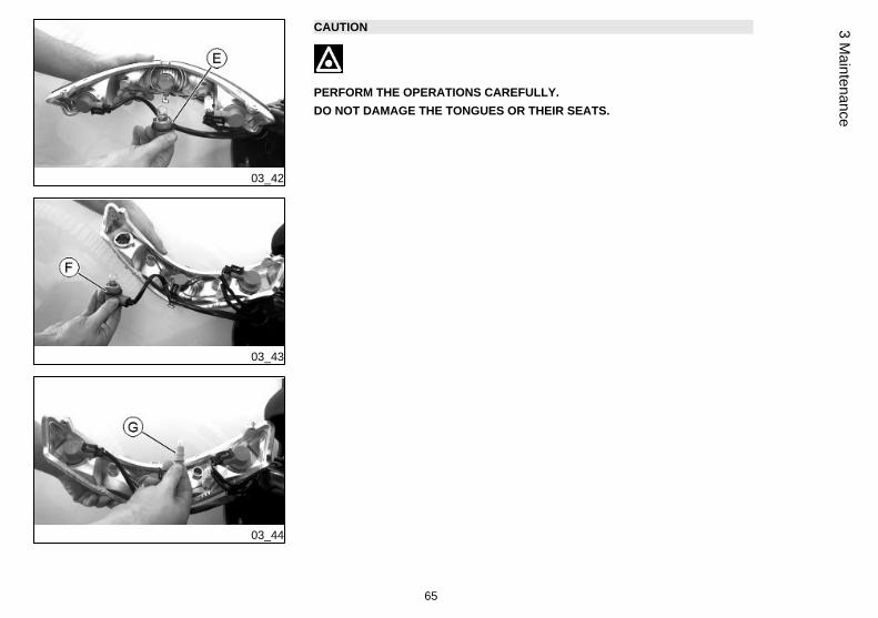
Rear optical unit (03_36, 03_37, 03_38, 03_39, 03_40, 03_41,03_42, 03_43, 03_44)
To reach the rear light unit bulbs, proceed as follow:
1. Undo the five screws « A» in order to remove the rear luggage rack.
2. Undo the two screws «B» and slide off the fairing of the rear light unit.
3. Undo the two screws «C».
4. Undo screw «D».
5. Take out the rear light.
CAUTION
PERFORM THE OPERATIONS CAREFULLY.DO NOT DAMAGE THE TONGUES OR THEIR SEATS. HANDLE THE PAINTEDAND PLASTIC COMPONENTS CAREFULLY. DO NOT SCRATCH OR DAMAGETHEM.
63
3 Maintenance

03_39
03_40
03_41
To replace:
6. In order to remove the stop light bulb, turn bulb holder «E» anticlockwise. Press thebulb slightly and turn it anticlockwise.
7. In order to remove the turn indicator bulbs, turn bulb holder «F» anticlockwise. Pressthe bulb slightly and turn it anticlockwise.
8. In order to remove the parking light bulbs, take out the rubber bulb holder «G». Slideoff the bulb.
64
3 M
aint
enan
ce
03_42
03_43
03_44
CAUTION
PERFORM THE OPERATIONS CAREFULLY.DO NOT DAMAGE THE TONGUES OR THEIR SEATS.
65
3 Maintenance

03_45
Number plate light (03_45)
Remove the screw «C», then take out the bulb holder.
03_46
03_47
Rear-view mirrors (03_46, 03_47)
To adjust the mirror stem position, lift the rubber protection and loosen lock nut «A»;adjust the mirror stem adequately and tighten the lock nut. Refit the rubber protection.To adjust mirror angle, loosen lock nut «B», aim mirror adequately and tighten thelock nut.The rear-view mirror is assembled on a stem with a ball "joint". Therefore, the mirrorcan be adjusted to the desired position manually.
CAUTION
DO NOT ADJUST THE MIRRORS WHILE RIDING. THIS COULD CAUSE YOU TOLOOSE CONTROL OF THE VEHICLE.
66
3 M
aint
enan
ce
03_48
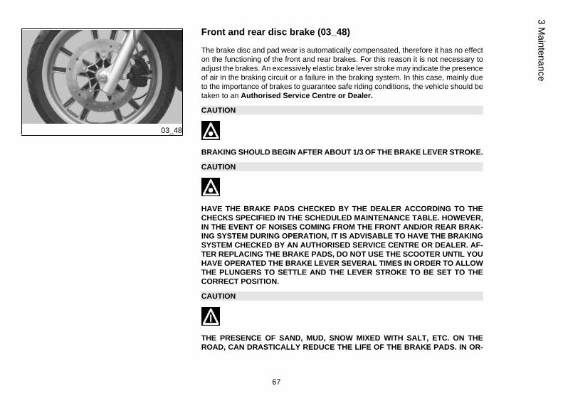
Front and rear disc brake (03_48)
The brake disc and pad wear is automatically compensated, therefore it has no effecton the functioning of the front and rear brakes. For this reason it is not necessary toadjust the brakes. An excessively elastic brake lever stroke may indicate the presenceof air in the braking circuit or a failure in the braking system. In this case, mainly dueto the importance of brakes to guarantee safe riding conditions, the vehicle should betaken to an Authorised Service Centre or Dealer.
CAUTION
BRAKING SHOULD BEGIN AFTER ABOUT 1/3 OF THE BRAKE LEVER STROKE.
CAUTION
HAVE THE BRAKE PADS CHECKED BY THE DEALER ACCORDING TO THECHECKS SPECIFIED IN THE SCHEDULED MAINTENANCE TABLE. HOWEVER,IN THE EVENT OF NOISES COMING FROM THE FRONT AND/OR REAR BRAK-ING SYSTEM DURING OPERATION, IT IS ADVISABLE TO HAVE THE BRAKINGSYSTEM CHECKED BY AN AUTHORISED SERVICE CENTRE OR DEALER. AF-TER REPLACING THE BRAKE PADS, DO NOT USE THE SCOOTER UNTIL YOUHAVE OPERATED THE BRAKE LEVER SEVERAL TIMES IN ORDER TO ALLOWTHE PLUNGERS TO SETTLE AND THE LEVER STROKE TO BE SET TO THECORRECT POSITION.
CAUTION
THE PRESENCE OF SAND, MUD, SNOW MIXED WITH SALT, ETC. ON THEROAD, CAN DRASTICALLY REDUCE THE LIFE OF THE BRAKE PADS. IN OR-
67
3 Maintenance

DER TO AVOID THIS, WE RECOMMEND WASHING THE VEHICLE FREQUENTLYWHEN RIDING IN THESE ROAD CONDITIONS.
Puncture
The vehicle is equipped with Tubeless tyres (without inner tube). In the event of apuncture, Tubeless tyres - unlike tyres with inner tubes - go flat very slowly, resultingin a greater steering safety. In the event of a puncture, an emergency repair can becarried out using an "inflate and repair" spray can. For a final repair, take your vehicleto an Authorised Service Centre or Dealer. The replacement of a tyre involves re-moving the wheel in question. Take your vehicle to an Authorised Service Centreor Dealer for these operations.
CAUTION
TO USE THE "INFLATE AND REPAIR" SPRAY CAN PROPERLY, FOLLOW THEINSTRUCTIONS ON THE PACKAGING.
WARNING
THE WHEELS FITTED WITH TYRES SHOULD ALWAYS BE BALANCED. RIDINGTHE VEHICLE WITH VERY LOW TYRE PRESSURE OR WITH INCORRECTLYBALANCED TYRES CAN LEAD TO DANGEROUS STEERING VIBRATIONS.
68
3 M
aint
enan
ce

03_49
Periods of inactivity (03_49)
We recommend carrying out the following operations:
1. Clean the scooter thoroughly and then cover it with a canvas;
2. With engine off and piston at the bottom dead centre, remove the spark plug, add1÷2 cm³ of oil through its hole (larger amounts are dangerous for the engine itself).Operate the starter button 1-2 times for roughly 1 second to turn the engine overslowly, then insert the spark plug again;
3. Drain all the fuel from the scooter; spread antirust grease on the uncoated metalparts; keep the wheels lifted above the ground by resting the chassis on two woodenwedges;
4. As regards the battery, follow the instructions in the «Battery» section.
Recommended productsAGIP CITY HI TEC 4T
Oil to lubricate flexible transmissions (throttle control)Oil for 4-stroke engines
Cleaning the vehicle
Use a low pressure jet of water to soften the caked dirt and mud deposited on thepainted surfaces. Once softened, sponge off mud and dirt using a car body spongesoaked in a car body shampoo and water solution (2-4% of car shampoo in water).Then rinse with abundant water, and dry with a shammy cloth. For the engine exterior,use petrol, a brush and clean cloths. Petrol can damage paintwork. Remember thatany polishing with silicone wax must always be preceded by washing.
69
3 Maintenance
CAUTION
DETERGENTS CAN POLLUTE WATER. THE VEHICLE MUST BE WASHED AT AWASH STATION EQUIPPED WITH A SPECIAL WATER PURIFICATION SYSTEM.
WARNING
THE USE OF A HIGH-PRESSURE WATER JET IS STRONGLY DISCOURAGEDFOR ANY ENGINE CLEANING OPERATION; HOWEVER, IF NO OTHER MEANSARE AVAILABLE, IT IS THEN NECESSARY TO:• ONLY USE A FANLIKE SPRAY JET.
• DO NOT PLACE THE NOZZLE CLOSER THAN 60 CM.
• DO NOT USE WATER AT TEMPERATURES OVER 40ºC.
• DO NOT USE HIGH-PRESSURE WATER JETS.
• DO NOT STEAM WASH.
• DO NOT AIM THE JET DIRECTLY AT: THE THROTTLE BODY, WIRING ANDSLOT DIFFUSER ON THE TRANSMISSION COVER.
CAUTION
NEVER WASH THE SCOOTER IN DIRECT SUNLIGHT, ESPECIALLY IN SUMMERWHEN THE BODYWORK IS STILL HOT AS THE SHAMPOO COULD DAMAGETHE PAINTWORK IF IT DRIES BEFORE BEING RINSED OFF. NEVER USECLOTHS SOAKED IN ALCOHOL, PETROL, DIESEL OIL OR KEROSENE FORCLEANING THE PAINTED OR PLASTIC SURFACES, IN ORDER NOT TO DAM-AGE THE LUSTRE FINISH OR ALTER THEIR MECHANICAL PROPERTIES. US-ING SILICONE-BASED WAX CAN DAMAGE THE PAINTED SURFACES, DE-PENDING ON THE VEHICLE COLOUR (SATIN COLOURS). FOR FURTHER
70
3 M
aint
enan
ce
INFORMATION ON THIS MATTER, CONTACT AN AUTHORISED SERVICE CEN-TRE.
Troubleshooting
STARTING FAILUREEmergency switch in «OFF» Set the switch back to «ON»
Fuse blown Replace the blown fuse and havethe vehicle checked by anAuthorised Service Centre.
STARTING DIFFICULTIES (SEE «START-UP PROBLEMS» SECTION)Lack of fuel in tank. Refuelling
Injection system fault Contact an Authorized ServiceCentre
Fuel pump fault Contact an Authorized ServiceCentre
Flat battery Recharge the battery.
* IMPORTANT: DO NOT USE THE SCOOTER TO THE COMPLETEEXHAUSTION OF FUEL; SHOULD THIS OCCUR, DO NOTATTEMPT TO START THE ENGINE. TURN THE IGNITION KEY TO
71
3 Maintenance

«OFF» AND TOP-UP THE FUEL TANK AS SOON AS POSSIBLE.FAILURE TO FOLLOW THESE GUIDELINES COULD DAMAGE THEFUEL PUMP AND/OR THE CATALYTIC CONVERTER.
IGNITION PROBLEMS
Faulty spark plug Contact an Authorised ServiceCentre.
Faulty ignition / injection controlunit. Due to the presence of highvoltage, this check should only becarried out by an expert.
Contact an Authorized ServiceCentre
LACK OF COMPRESSION
Loose spark plug. Screw in the spark plug tightly
Cylinder head loose, piston gasrings worn.
Contact an Authorised ServiceCentre.
Valve stuck Contact an Authorised ServiceCentre.
HIGH CONSUMPTION AND LOW PERFORMANCEClogged or dirty air filter Try to blow out with compressed
air, otherwise replace the filter
72
3 M
aint
enan
ce

INSUFFICIENT BRAKINGGreasy disc. Worn pads. Faultybraking system. Presence of air inthe front and rear brake circuit.
Contact an Authorised ServiceCentre.
INEFFICIENT SUSPENSIONShock absorber fault, oil leak, endbuffers damaged; shock absorberpreloading incorrectly set
Contact an Authorised ServiceCentre.
AUTOMATIC TRANSMISSION PROBLEMSCVT rollers and/or drive beltdamaged
Contact an Authorised ServiceCentre.
73
3 Maintenance

74
3 M
aint
enan
ce

Carnaby Cruiser 300 ie
Chap. 04Technical data
75

04_01
76
4 Te
chni
cal d
ata

ENGINE TECHNICAL DATAType Single-cylinder, 4-stroke
Engine capacity 278 cm³
Bore x stroke 75 X 63 mm
Compression ratio 11 ± 0.5 : 1
Engine idle speed 1,700 ± 100 rpm
Timing system 4 valves, single overheadcamshaft, chain-driven.
Valve clearance Intake: 0.10 mm Exhaust: 0.15 mm
Max. power 16.1 kW at 7,250 rpm
MAX. torque 23 Nm at 6,000 rpm
Transmission CVT expandable pulley variatorwith torque server, V-belt, self-ventilating dry automaticcentrifugal clutch and transmissionhousing with forced-circulation aircooling.
Final reduction gear Gear reduction unit in oil bath.
Lubrication Engine lubrication with lobe pump(inside crankcase), chain-driven,with double filter: mesh and paper.
Cooling Forced coolant circulation system.
Electric start-up Oil-coated freewheel and torquelimiter.
Ignition Electronic inductive dischargeignition, high efficiency, withseparate HV coil.
77
4 Technical data

Ignition advance α/N three-dimensional mapmanaged by control unit
Spark plug NGK CR8EKB
Alternative spark plug -
Fuel system 32 MIU1.E9 Electronic injection,with Ø 32-mm throttle body andelectric fuel pump.
Fuel Unleaded petrol (95 RON)
Exhaust silencer Absorption-type exhaust silencerwith a 3-way catalytic converterand lambda probe.
Emissions compliance EURO 3
VEHICLE TECHNICAL DATAChassis Tubular and steel sheets.
Front suspension Hydraulic telescopic fork with Ø 35-mm stem
Rear suspension Two double-acting shockabsorbers, adjustable to fourpositions at preloading.
Front brake Ø 260-mm disc brake withhydraulic control activated byhandlebar right-side lever.
Rear brake Ø 260-mm disc brake withhydraulic control activated byhandlebar left-side lever.
78
4 Te
chni
cal d
ata

Wheel rim type Light alloy wheel rims.
Front wheel rim 16'' x 3.00
Rear rim 16 x 3.50''
Front tyre Tubeless, 110/70 - 16'' 52P
Rear tyre 130/70- 16'' 61P Tubeless
Front tyre pressure (withpassenger)
2 bar (-)
Rear tyre pressure (withpassenger)
2.3 bar (-)
Kerb weight 163 kg ± 5 kg
Maximum weight allowed 350 kg
Battery Sealed, 12 V / 10 Ah
CAPACITYEngine oil 1.3 l
Transmission oil 250 cm³
Cooling system fluid 1.75 l
Fuel tank (reserve) ~ 10 l (2 l)
79
4 Technical data

04_02
Toolkit (04_02)
The tools are stored in the helmet compartment.The kit includes:
1. One toolkit pouch
2. One twin screwdriver
3. One box-spanner
4. One wrench for adjusting shock absorbers
5. One extractor for blade fuses
6. One flat wrench
7. One Allen key
80
4 Te
chni
cal d
ata

Carnaby Cruiser 300 ie
Chap. 05Spare parts and
accessories
81

05_01
Warnings (05_01)
WARNING
TO PREVENT ACCIDENTS AND TO GUARANTEE PROPER STABILITY, PER-FORMANCE AND SAFETY, RIDE THE VEHICLE VERY CAREFULLY WHEN IT ISFITTED WITH ACCESSORIES OR WITH UNUSUAL LOADS.
WARNING
IT IS ALSO RECOMMENDED THAT ORIGINAL PIAGGIO SPARE PARTS BEUSED, AS THESE ARE THE ONLY ONES OFFERING YOU THE SAME QUALITYGUARANTEE AS THOSE INITIALLY FITTED ON THE SCOOTER. THE USE OFNON-ORIGINAL SPARE PARTS RENDERS THE WARRANTY VOID.
WARNING
PIAGGIO MARKETS ITS OWN LINE OF ACCESSORIES THAT ARE RECOG-NISED AND GUARANTEED FOR USE. IT IS THEREFORE ESSENTIAL TO CON-TACT AN AUTHORISED DEALER OR SERVICE CENTRE IN ORDER TO CHOOSEAND FIT ACCESSORIES CORRECTLY. THE USE OF NON-ORIGINAL ACCES-SORIES MAY AFFECT THE STABILITY AND OPERATION OF YOUR VEHICLEAND REDUCE SAFETY LEVELS WITH POTENTIAL RISKS FOR THE RIDER.
82
5 Sp
are
parts
and
acc
esso
ries
WARNING
NEVER RIDE THE SCOOTER EQUIPPED WITH ACCESSORIES (TOP BOX AND/OR WINDSHIELD) AT A SPEED HIGHER THAN 100 km/h.
THE SCOOTER CAN BE RIDDEN AT A HIGHER SPEED WITHOUT THE ACCES-SORIES MENTIONED BEFORE WITHIN THE LIMITS ESTABLISHED BY LAW.
IF THERE ARE ANY NON-PIAGGIO ACCESSORIES INSTALLED, OR AN AB-NORMAL LOAD, OR IF THE SCOOTER IS NOT IN A GENERALLY GOOD CON-DITION, OR WHENEVER WEATHER CONDITIONS DEMAND IT, SPEED SHOULDBE FURTHER REDUCED.
WARNING
BE EXTREMELY CAREFUL WHEN INSTALLING AND REMOVING THE MECHAN-ICAL ANTITHEFT DEVICE ON THE VEHICLE (U-SHAPED PADLOCK, DISCBLOCK, ETC.).
MAINLY NEAR THE BRAKE PIPES, TRANSMISSIONS AND/OR ELECTRIC CA-BLES, AN INCORRECT INSTALLATION OR REMOVAL OF THE ANTITHEFTDEVICE AS WELL AS LEAVING IT ON BEFORE STARTING THE VEHICLE CANSERIOUSLY DAMAGE ITS COMPONENTS, COMPROMISE THE CORRECTFUNCTIONING OF THE VEHICLE AND USERS' SAFETY.
83
5 Spare parts and accessories

84
5 Sp
are
parts
and
acc
esso
ries
Carnaby Cruiser 300 ie
Chap. 06Scheduled
maintenance
85

06_01
Scheduled servicing table (06_01)
Adequate maintenance is fundamental to ensure long-lasting, optimum operation andperformance of your vehicle.
For this purpose, PIAGGIO offers a set of checks and maintenance services (for pay-ment) which are included in the summary table shown on the following page. Anyminor faults should be reported without delay to an Authorised Service Centre orDealer without waiting until the next scheduled service to solve it.
All scheduled maintenance services must be carried out at the specified intervals,even if the stated mileage has not yet been reached. Punctual scooter servicing isessential to ensure your warranty remains valid. For any further information concern-ing Warranty procedures and 'Scheduled Maintenance', please refer to the 'WarrantyBooklet'.
MAINTENANCE TABLE
Km x 1,000 1 5 10 15 20 25 30 35 40 45 50 55 60 65 70 75 80
Driven pulley roller casing L L L L L L L L
Safety fasteners I I I I I
Ignition spark plug R R R R R R R R
Centre stand bracket L L L L L L L L L L L L L L L L
Driving belt R R R R R R R R
Throttle control A A A A A A A A A
Air filter I I I I I I I I
Oil filter R R R R R R R R R
Valve clearance A A A A
Electrical system and battery I I I I I I I I I
86
6 Sc
hedu
led
mai
nten
ance
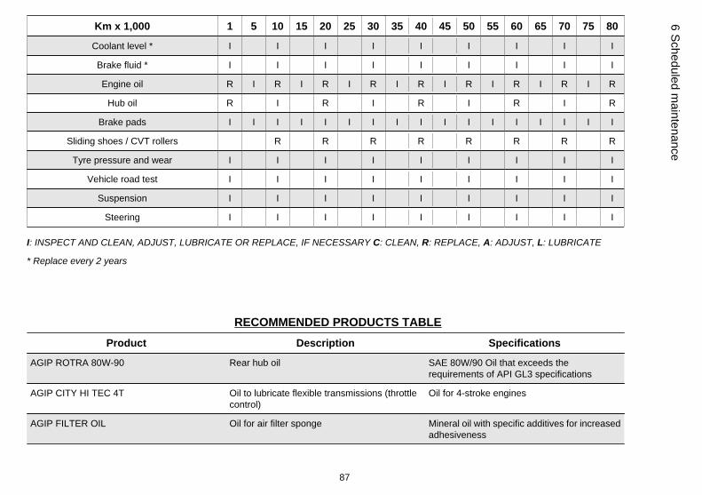
Km x 1,000 1 5 10 15 20 25 30 35 40 45 50 55 60 65 70 75 80
Coolant level * I I I I I I I I I
Brake fluid * I I I I I I I I I
Engine oil R I R I R I R I R I R I R I R I R
Hub oil R I R I R I R I R
Brake pads I I I I I I I I I I I I I I I I I
Sliding shoes / CVT rollers R R R R R R R R
Tyre pressure and wear I I I I I I I I I
Vehicle road test I I I I I I I I I
Suspension I I I I I I I I I
Steering I I I I I I I I I
I: INSPECT AND CLEAN, ADJUST, LUBRICATE OR REPLACE, IF NECESSARY C: CLEAN, R: REPLACE, A: ADJUST, L: LUBRICATE
* Replace every 2 years
RECOMMENDED PRODUCTS TABLEProduct Description Specifications
AGIP ROTRA 80W-90 Rear hub oil SAE 80W/90 Oil that exceeds therequirements of API GL3 specifications
AGIP CITY HI TEC 4T Oil to lubricate flexible transmissions (throttlecontrol)
Oil for 4-stroke engines
AGIP FILTER OIL Oil for air filter sponge Mineral oil with specific additives for increasedadhesiveness
87
6 Scheduled maintenance

Product Description Specifications
AGIP GP 330 Grease for brake levers, throttle White calcium complex soap-based spraygrease with NLGI 2; ISO-L-XBCIB2
AGIP CITY HI TEC 4T Engine oil SAE 5W-40, API SL, ACEA A3, JASO MASynthetic oil
AGIP BRAKE 4 Brake fluid FMVSS DOT 4 Synthetic fluid
AGIP PERMANENT SPECIAL coolant Monoethylene glycol-based antifreeze fluid,CUNA NC 956-16
UNIT OF MEASURE - CONVERSION - ENGLISH SYSTEMTO INTERNATIONAL SYSTEM (IS).
1 Inch (in) 25.4 Millimetres (mm)
1 Foot (ft) 0.305 Meter (m)
1 Mile (mi) 1.609 Kilometre (km)
1 US Gallon (USgal) 3.785 Litre (l)
1 Pound (lb) 0.454 Kilogram (kg)
1 Cubic inch (in³) 16.4 Cubic centimetres (cm³)
1 Foot pound (ft lb) 1,356 Newton meter (Nm)
1 Mile per hour (mi/h) 1,602 Kilometres per hour (km/h)
1 Pound per square inch (PSI) 0.069 (bar)
1 Fahrenheit (°F) 32+(9/5) Celsius (°C)
88
6 Sc
hedu
led
mai
nten
ance

TABLE OF CONTENTS
AAir filter: 47
BBattery: 51, 52Brake: 50, 67
CChecks: 28
DDisc brake: 67
EEngine oil: 40, 41Engine stop: 17
FFuel: 21Fuses: 54
HHeadlight: 61Horn: 15Hub oil: 43
IIdentification: 23Immobilizer: 18, 20Instrument panel: 10
KKey switch: 13Keys: 17
LLight switch: 16
MMaintenance: 39, 85Mirrors: 66
PPuncture: 68
RRefuelling: 28
SSaddle: 22Scheduled maintenance: 85Shock absorbers: 30Spark plug: 46Stand: 35
Start-up: 16Switch: 13, 15, 16
TTank: 21Technical Data: 75Toolkit: 80Transmission: 35Tyre pressure: 29Tyres: 44
VVehicle: 7, 69
89

The descriptions and illustrations given in this publication are not binding. While the basic specifications as described and illustrated in this manualremain unchanged, PIAGGIO-GILERA reserves the right, at any time and without being required to update this publication beforehand, to make anychanges to components, parts or accessories, which it considers necessary to improve the product or which are required for manufacturing or con-struction reasons.
Not all versions/models shown in this publication are available in all countries. The availability of each model should be checked at the official Piaggio sales network.
"© Copyright 2008 - PIAGGIO & C. S.p.A. Pontedera. All rights reserved. Reproduction of this publication in whole or in part is prohibited."
PIAGGIO & C. S.p.A. - Aftersales
V.le Rinaldo Piaggio, 23 - 56025 PONTEDERA (Pi)