Embed Size (px)
Citation preview

PIC DiscussionBy: Eng. Tamar Jomaa
MicroC programming
MicroC Programming
Outlines of part A:
1) MicroC Basics
2) Simple Examples
3) Lab#8:Introduction to MicroC programming
1) MicroC Basics
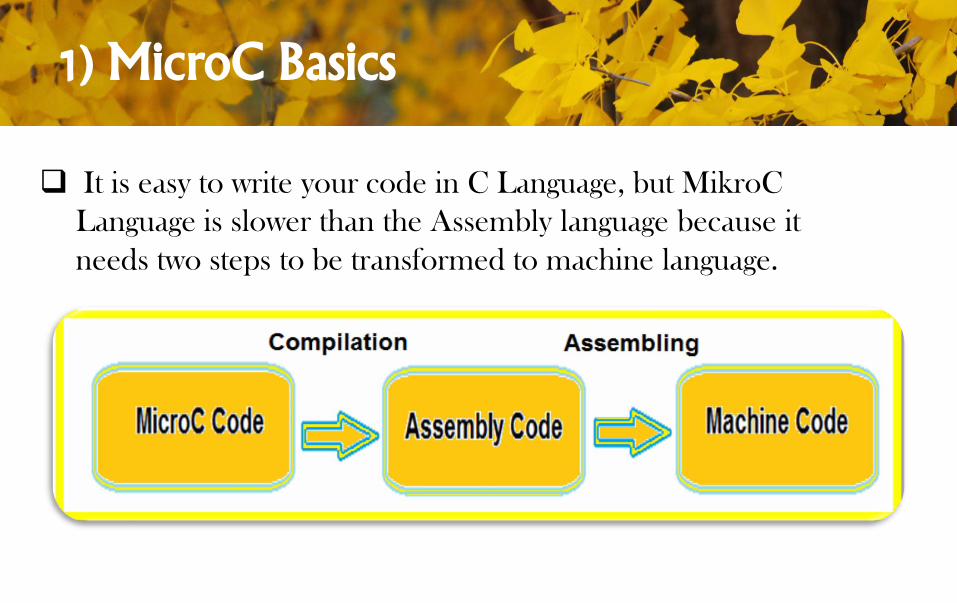
It is easy to write your code in C Language, but MikroC
Language is slower than the Assembly language because it
needs two steps to be transformed to machine language.
1) MicroC Basics
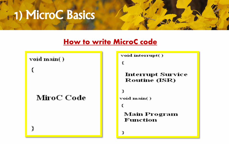
How to write MicroC code
1) MicroC Basics
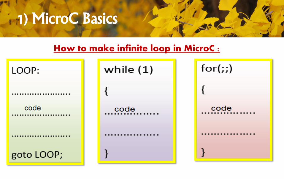
How to make infinite loop in MicroC :
1) MicroC Basics
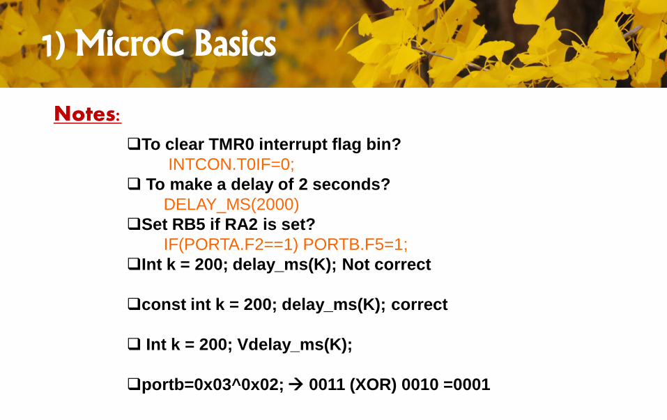
To clear TMR0 interrupt flag bin?
INTCON.T0IF=0;
To make a delay of 2 seconds?
DELAY_MS(2000)
Set RB5 if RA2 is set?
IF(PORTA.F2==1) PORTB.F5=1;
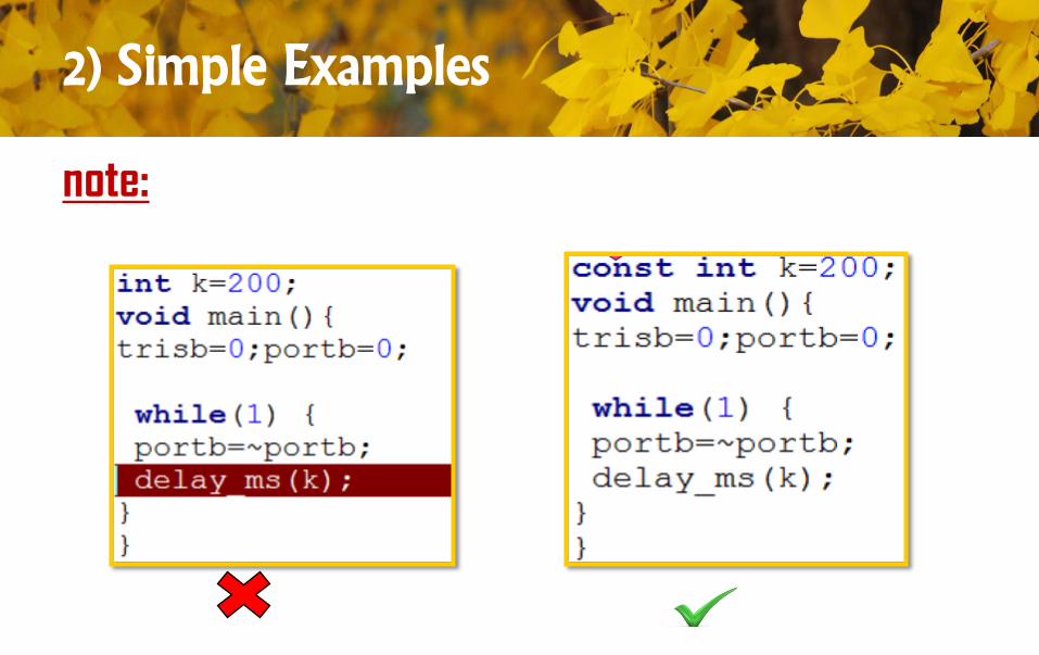
Int k = 200; delay_ms(K); Not correct
const int k = 200; delay_ms(K); correct
Int k = 200; Vdelay_ms(K);
portb=0x03^0x02; 0011 (XOR) 0010 =0001
Notes:
1) MicroC Basics
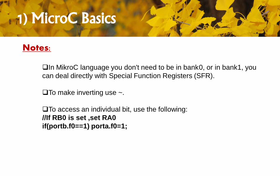
In MikroC language you don't need to be in bank0, or in bank1, you
can deal directly with Special Function Registers (SFR).
To make inverting use ~.
To access an individual bit, use the following:
//If RB0 is set ,set RA0
if(portb.f0==1) porta.f0=1;
Notes:
1) MicroC Basics
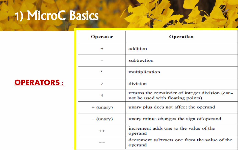
OPERATORS :
1) MicroC Basics
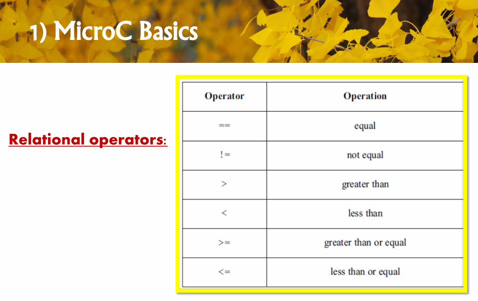
Relational operators:
1) MicroC Basics
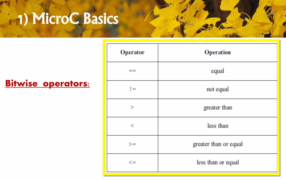
Bitwise operators:
1) MicroC Basics
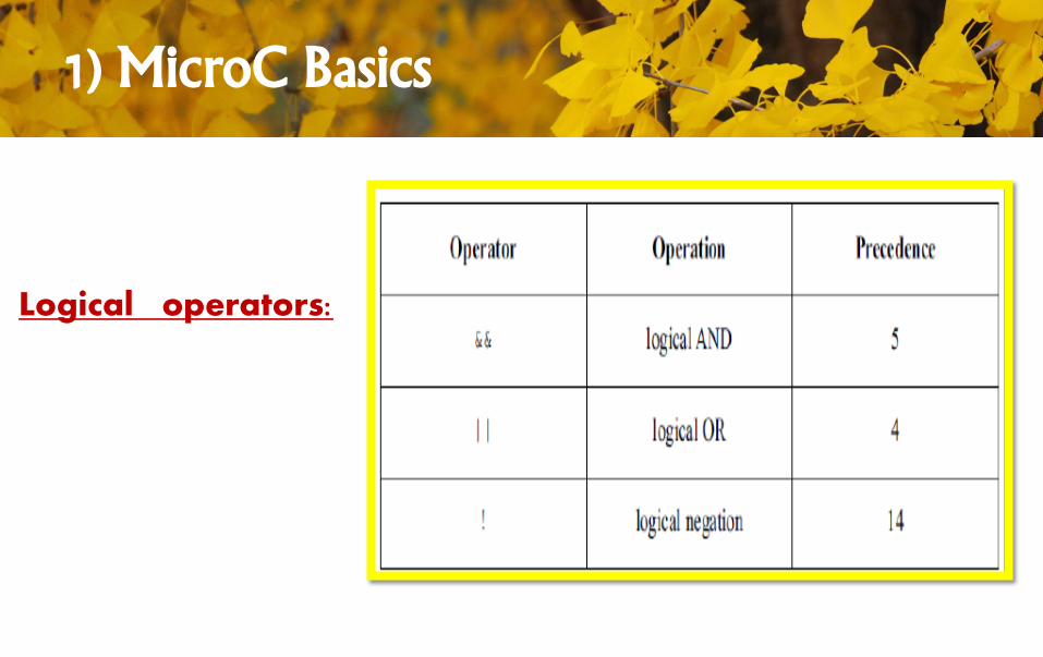
Logical operators:
1) MicroC Basics
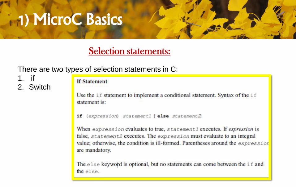
Selection statements:
There are two types of selection statements in C:
1. if
2. Switch

1) MicroC Basics
1) MicroC Basics
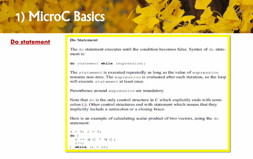
Do statement
1) MicroC Basics
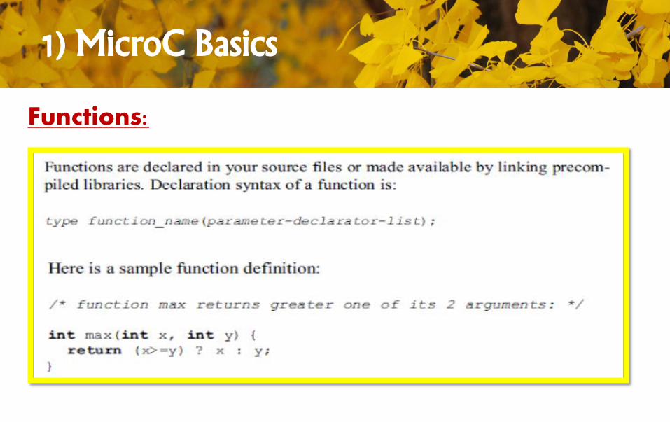
Functions:
1) MicroC Basics
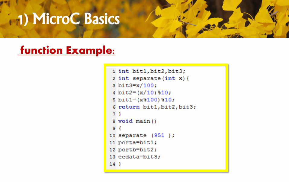
function Example:
1) MicroC Basics
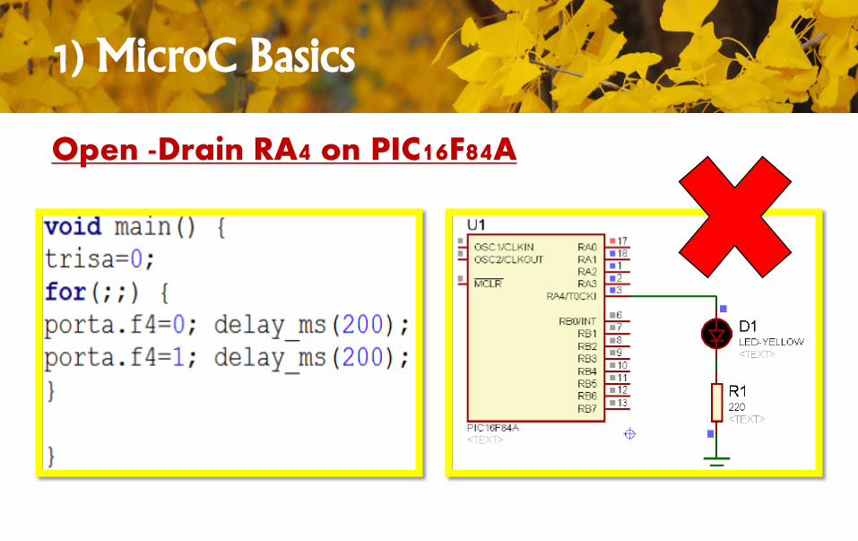
Open -Drain RA4 on PIC16F84A
1) MicroC Basics
Open -Drain RA4 on PIC16F84A
1) MicroC Basics
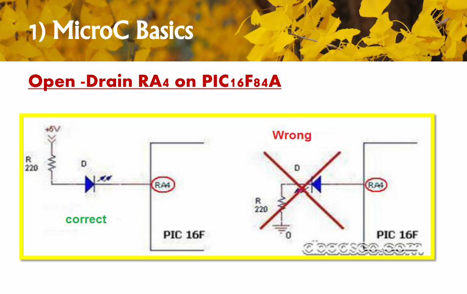
Open -Drain RA4 on PIC16F84ASome PICs like PIC16F84A have RA4 with open drain output instead of CMOS output!
RA4 is different; it is configured as an open drain MOSFET. When set to low, it
performs identically with the other pin architectures.
However, when set to high, there is no internal connection with VDD and hence it will not
directly source voltage.
If it’s necessary to use RA4 as a sourcing output pin, you can add an external “pull-up”
resistor, typically in the range of 470 ohms–4.7K ohms.
The sourced current then comes from the pull-up resistor. Unlike all other pins that cannot
exceed VDD, RA4’s open drain is rated to 12 volts.
1) MicroC Basics
Open -Drain RA4 on PIC16F84A
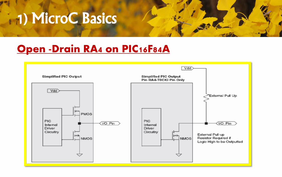
RA4 pin (pin 3 for PIC16F84a) is "Open-Drain" type output pin.
That means it cannot source current and it will be high impedance
when assigned logic '1' to it.
You cannot set this pin as an output pin by using 'TRISA=0x00'.
The solution is attaching a pull up resistor (10K) to the RA4 pin in
order to use this pin as an output pin.
1) MicroC Basics
Open -Drain RA4 on PIC16F84A
1) MicroC Basics
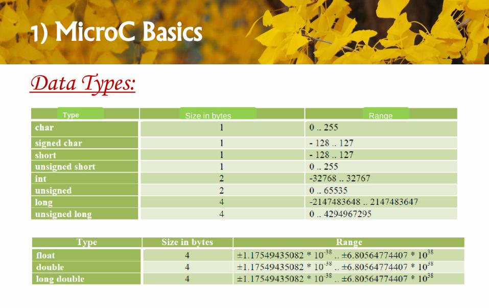
Data Types:
RangeSize in bytesType
1) MicroC Basics
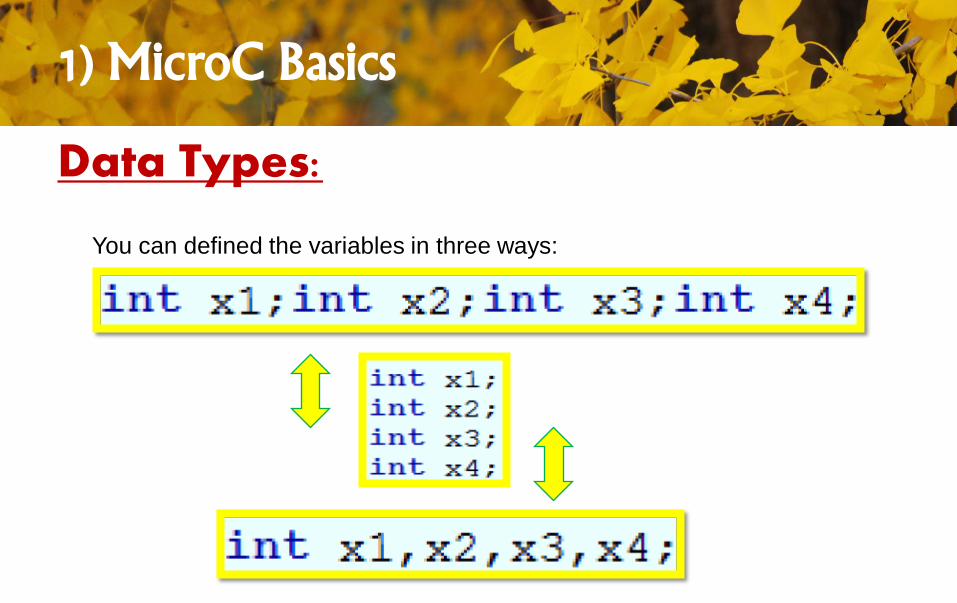
Data Types:
You can defined the variables in three ways:
1) MicroC Basics
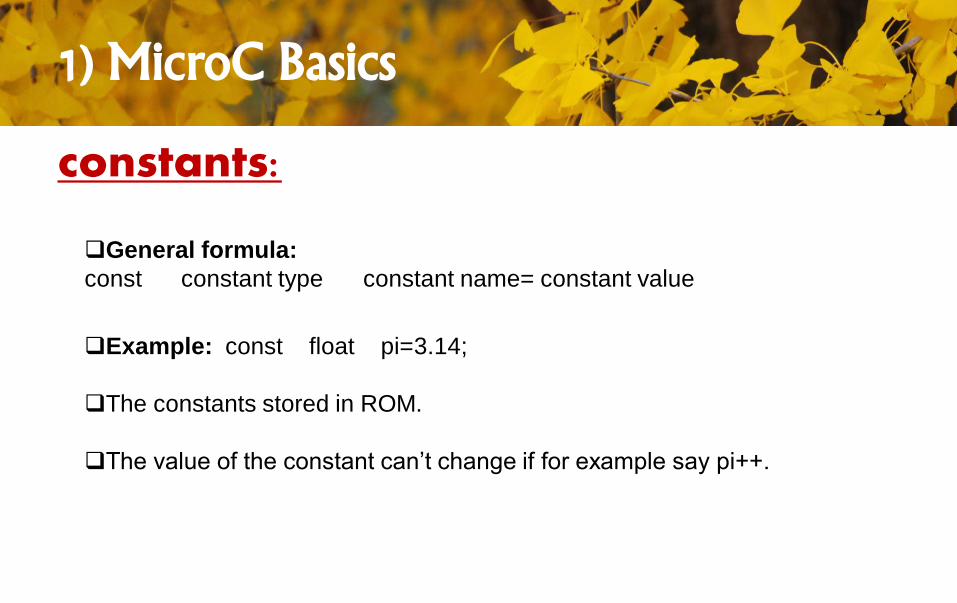
constants:
Example: const float pi=3.14;
The constants stored in ROM.
The value of the constant can’t change if for example say pi++.
General formula:
const constant type constant name= constant value
1) MicroC Basics
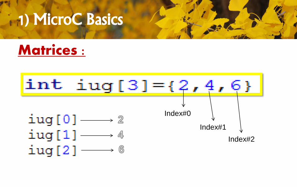
Matrices :
Index#0
Index#1
Index#2
1) MicroC Basics
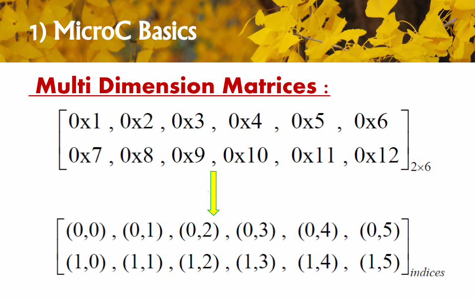
Multi Dimension Matrices :
1) MicroC Basics
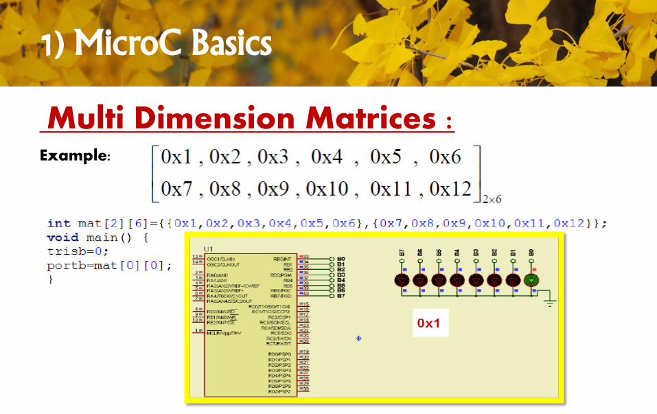
Multi Dimension Matrices :Example:
1) MicroC Basics
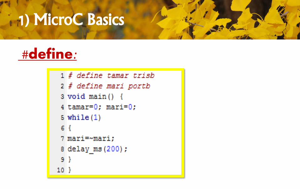
#define:
1) MicroC Basics
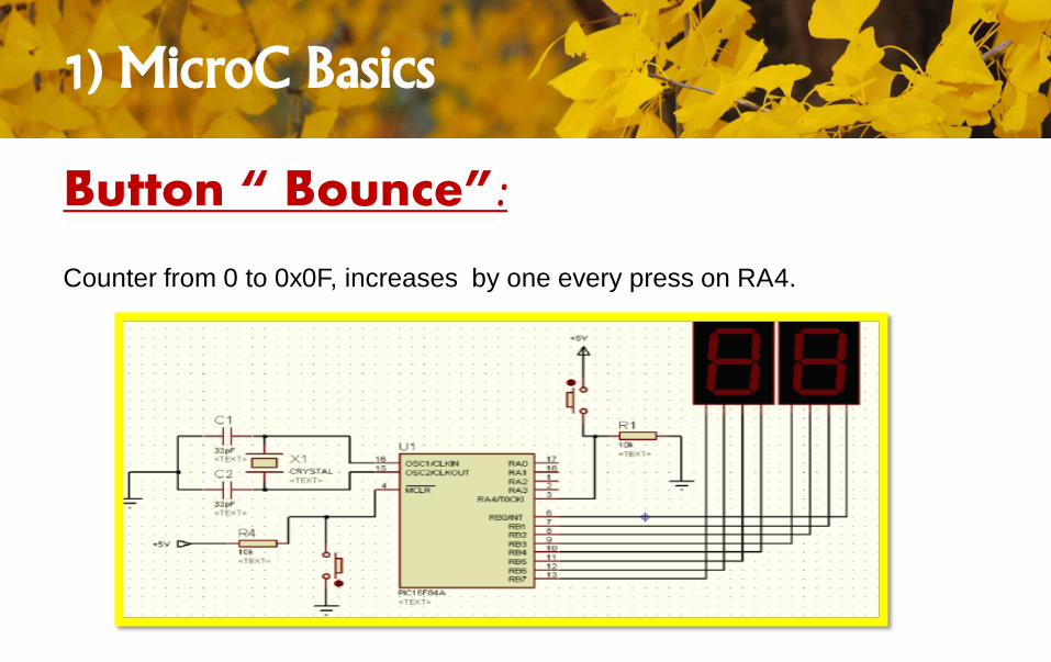
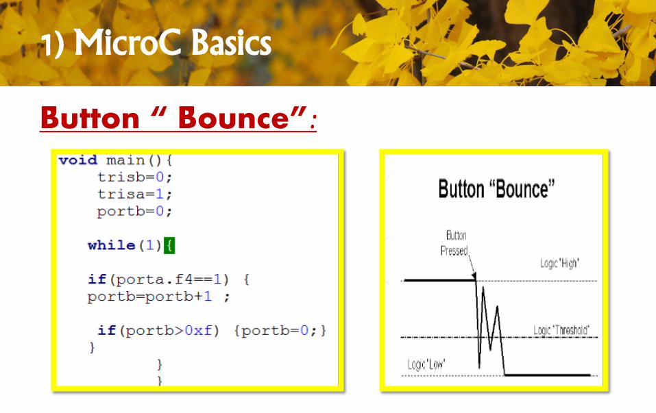
Button “ Bounce”:
Counter from 0 to 0x0F, increases by one every press on RA4.
1) MicroC Basics
Button “ Bounce”:
1) MicroC Basics
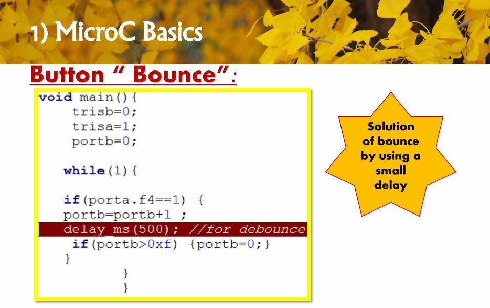
Button “ Bounce”:
Solution of bounce by using a
small delay
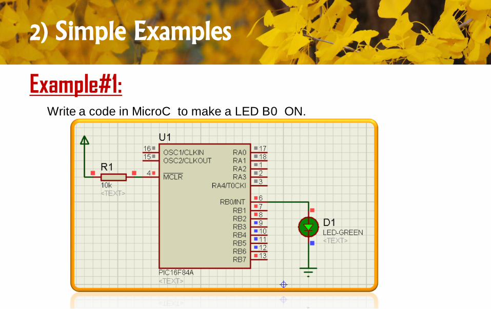
2) Simple Examples
Example#1:Write a code in MicroC to make a LED B0 ON.
2) Simple Examples
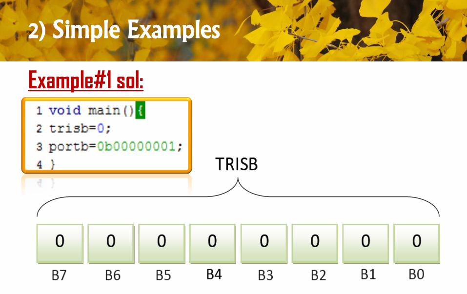
Example#1 sol:.
2) Simple Examples
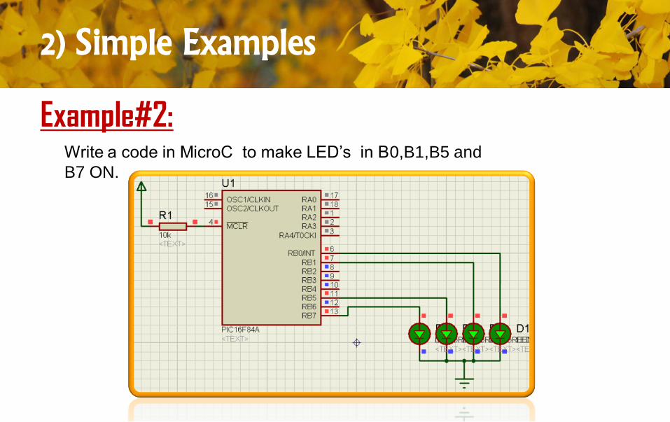
Example#2:Write a code in MicroC to make LED’s in B0,B1,B5 and
B7 ON.
2) Simple Examples
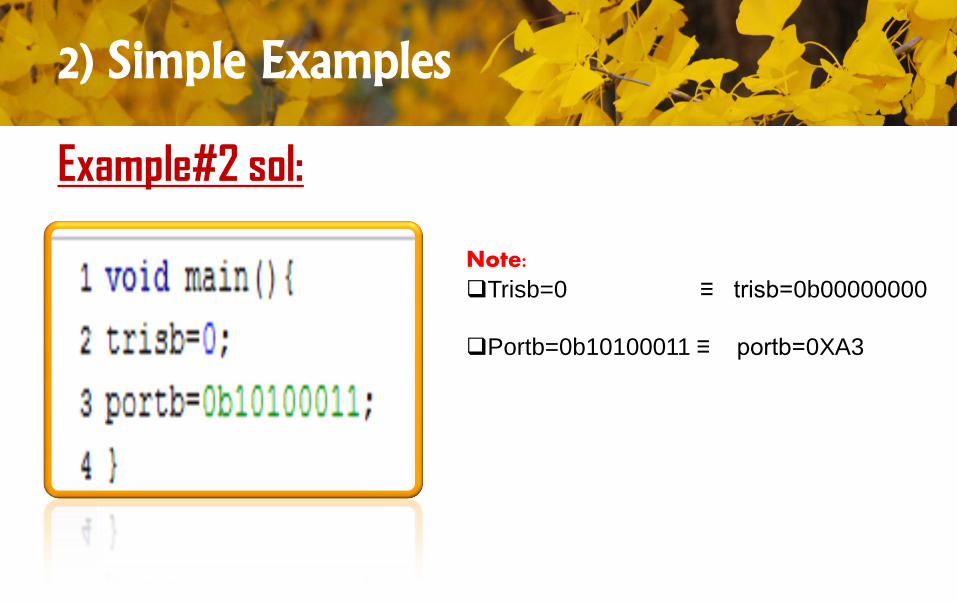
Example#2 sol:
Note:
Trisb=0 ≡ trisb=0b00000000
Portb=0b10100011 ≡ portb=0XA3
2) Simple Examples
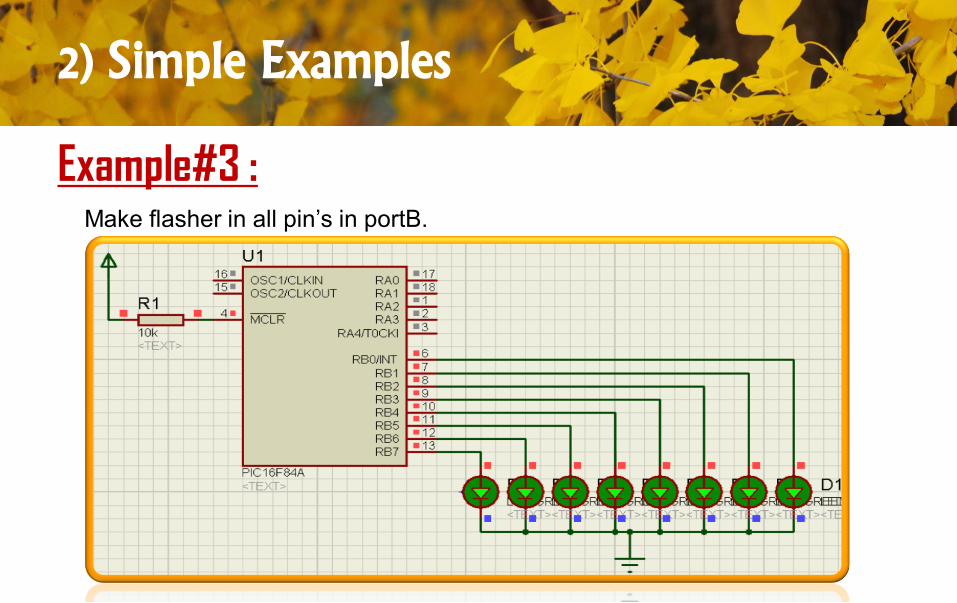
Example#3 :Make flasher in all pin’s in portB.
2) Simple Examples
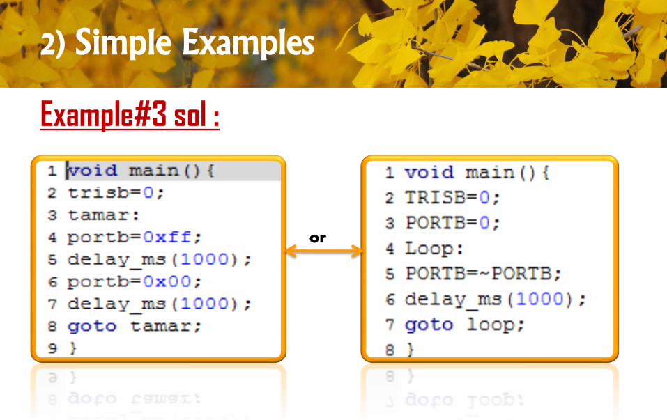
Example#3 sol :
or
2) Simple Examples
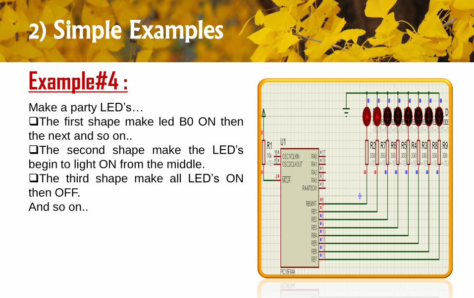
Example#4 :Make a party LED’s…
The first shape make led B0 ON then
the next and so on..
The second shape make the LED’s
begin to light ON from the middle.
The third shape make all LED’s ON
then OFF.
And so on..
2) Simple Examples
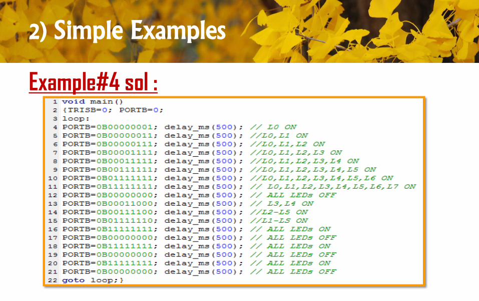
Example#4 sol :
2) Simple Examples
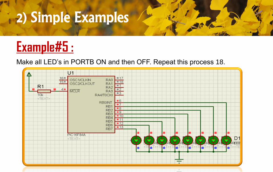
Example#5 :Make all LED’s in PORTB ON and then OFF. Repeat this process 18.
2) Simple Examples
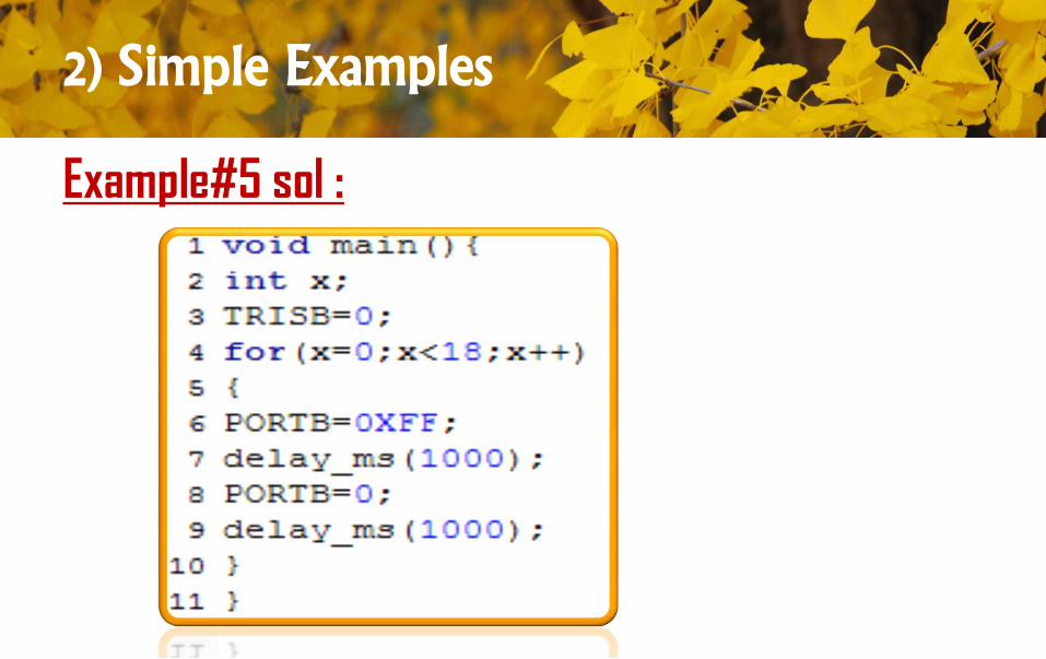
Example#5 sol :
2) Simple Examples
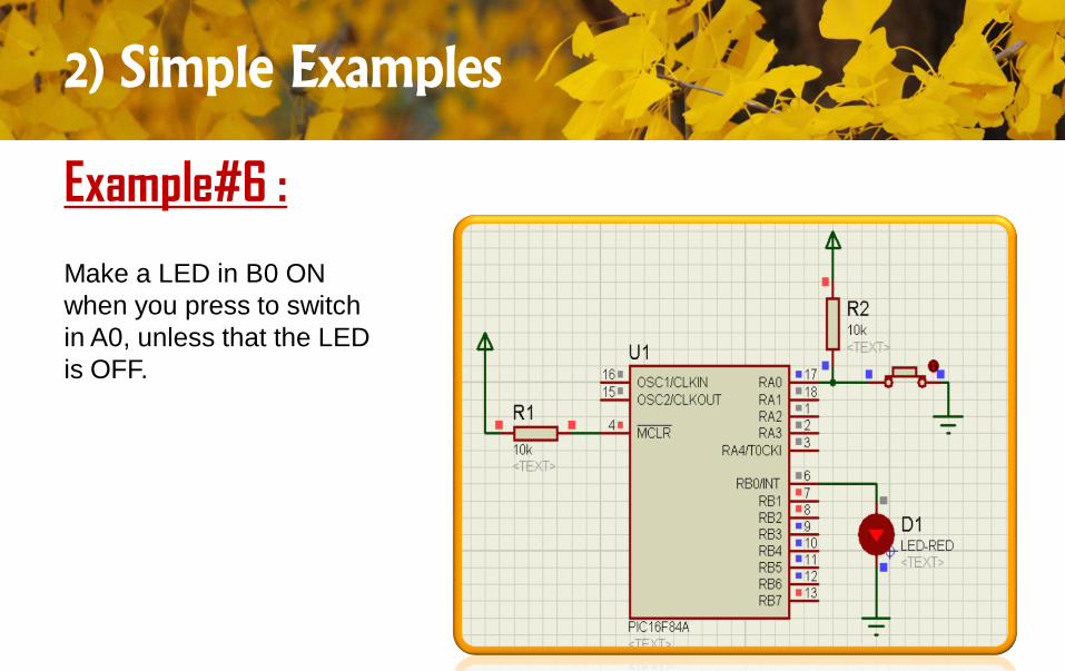
Example#6 :
Make a LED in B0 ON
when you press to switch
in A0, unless that the LED
is OFF.
2) Simple Examples
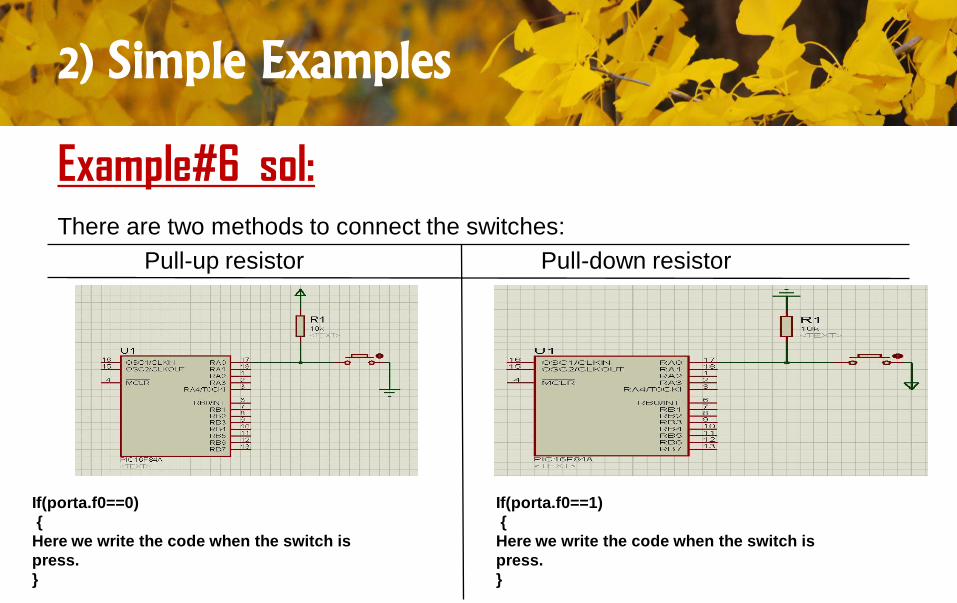
Example#6 sol:There are two methods to connect the switches:
Pull-up resistor Pull-down resistor
If(porta.f0==0)
{
Here we write the code when the switch is
press.
}
If(porta.f0==1)
{
Here we write the code when the switch is
press.
}
2) Simple Examples
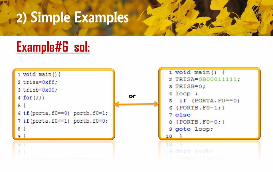
Example#6 sol:
or
2) Simple Examples
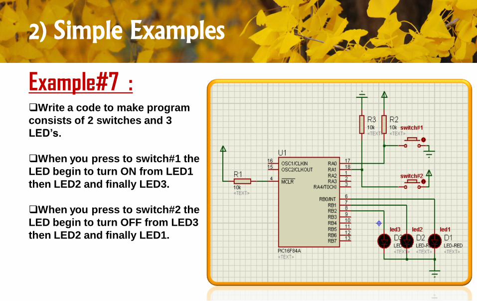
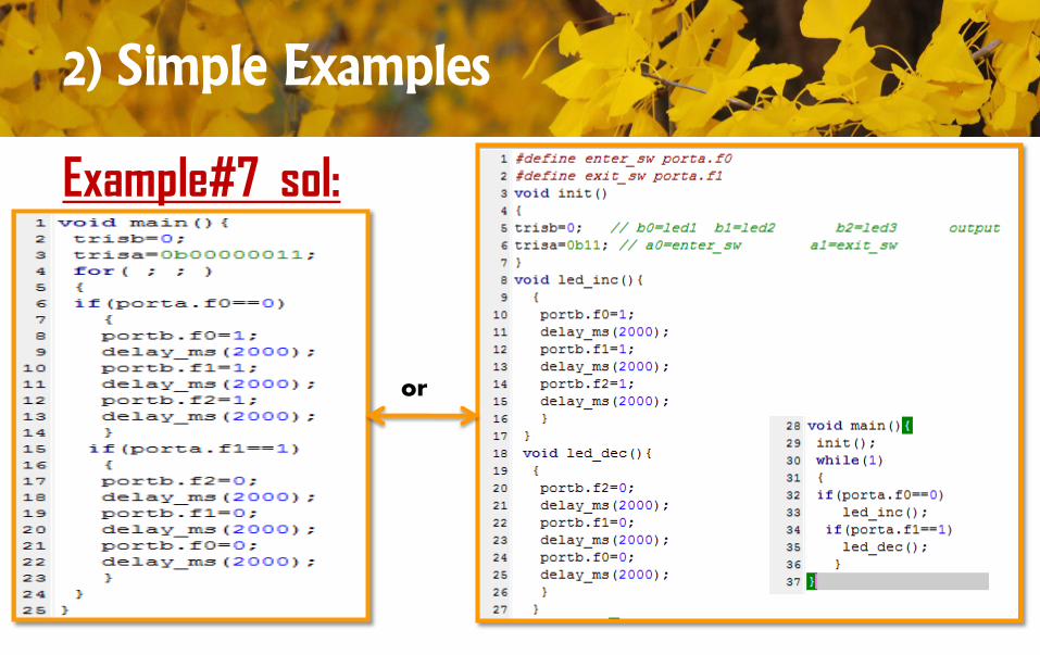
Example#7 :Write a code to make program
consists of 2 switches and 3
LED’s.
When you press to switch#1 the
LED begin to turn ON from LED1
then LED2 and finally LED3.
When you press to switch#2 the
LED begin to turn OFF from LED3
then LED2 and finally LED1.
2) Simple Examples
Example#7 sol:
or
2) Simple Examples
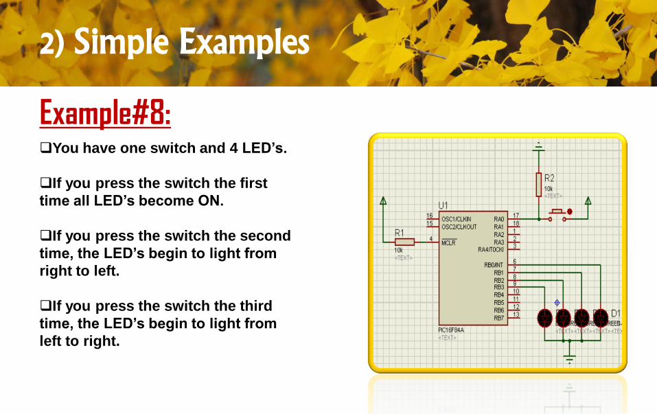
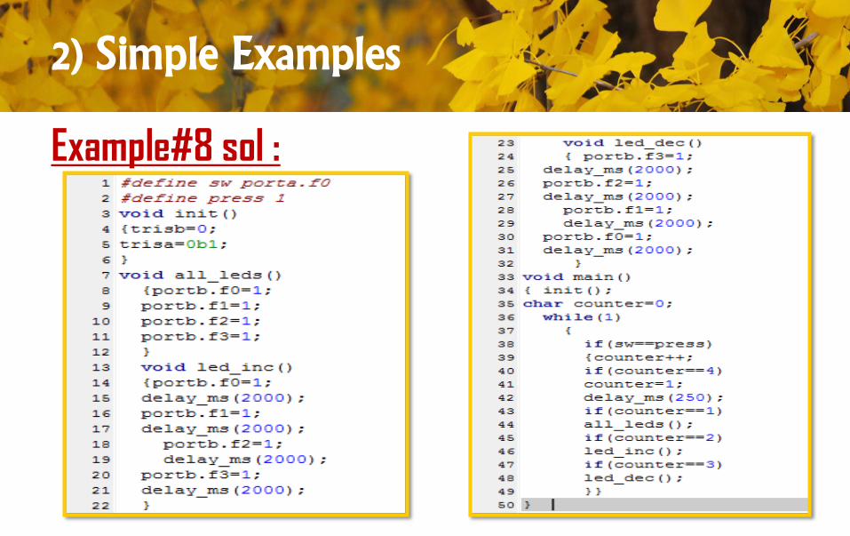
Example#8:You have one switch and 4 LED’s.
If you press the switch the first
time all LED’s become ON.
If you press the switch the second
time, the LED’s begin to light from
right to left.
If you press the switch the third
time, the LED’s begin to light from
left to right.
2) Simple Examples
Example#8 sol :
2) Simple Examples
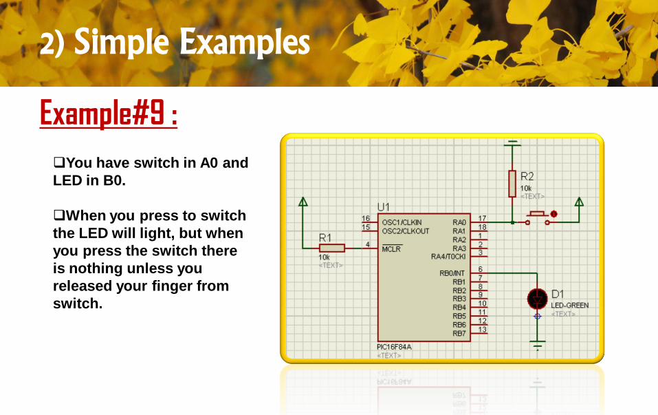
Example#9 :
You have switch in A0 and
LED in B0.
When you press to switch
the LED will light, but when
you press the switch there
is nothing unless you
released your finger from
switch.
2) Simple Examples
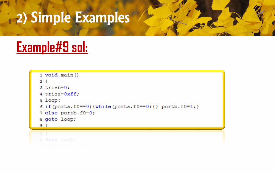
Example#9 sol:
2) Simple Examples
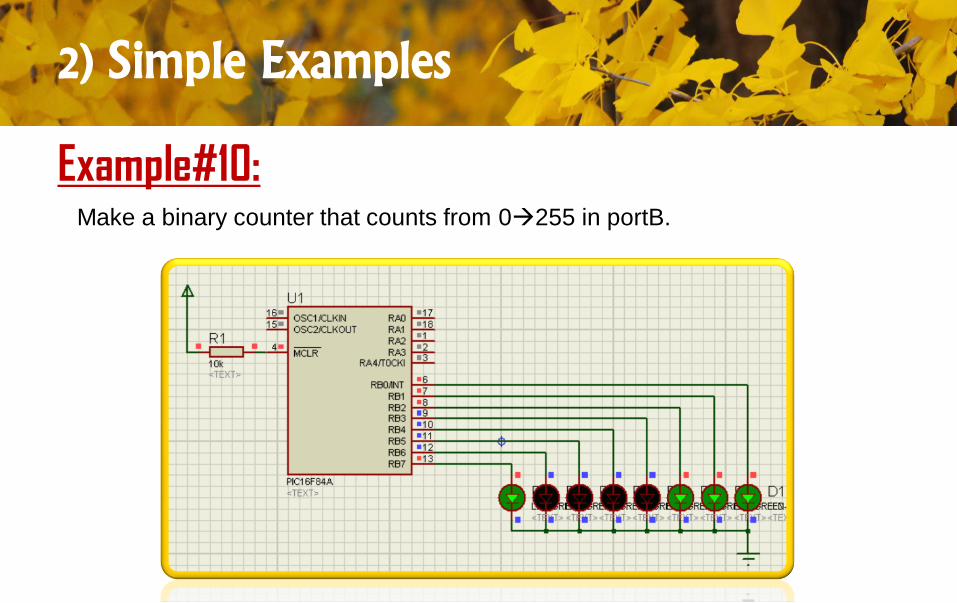
Example#10:Make a binary counter that counts from 0255 in portB.
2) Simple Examples
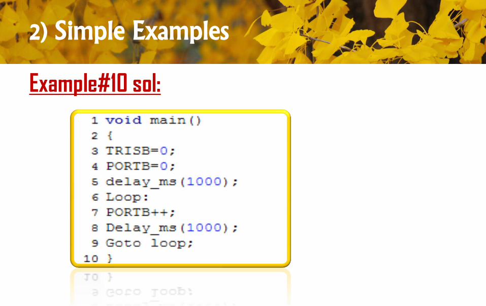
Example#10 sol:
2) Simple Examples
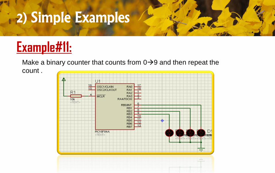
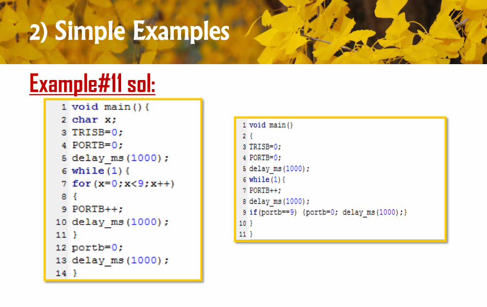
Example#11:Make a binary counter that counts from 09 and then repeat the
count .
2) Simple Examples
Example#11 sol:
2) Simple Examples
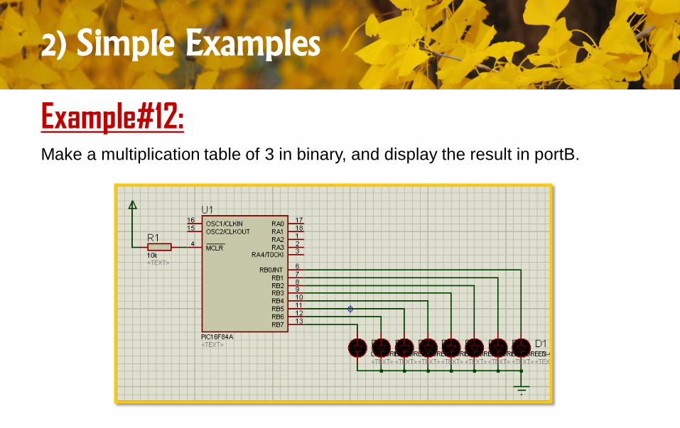
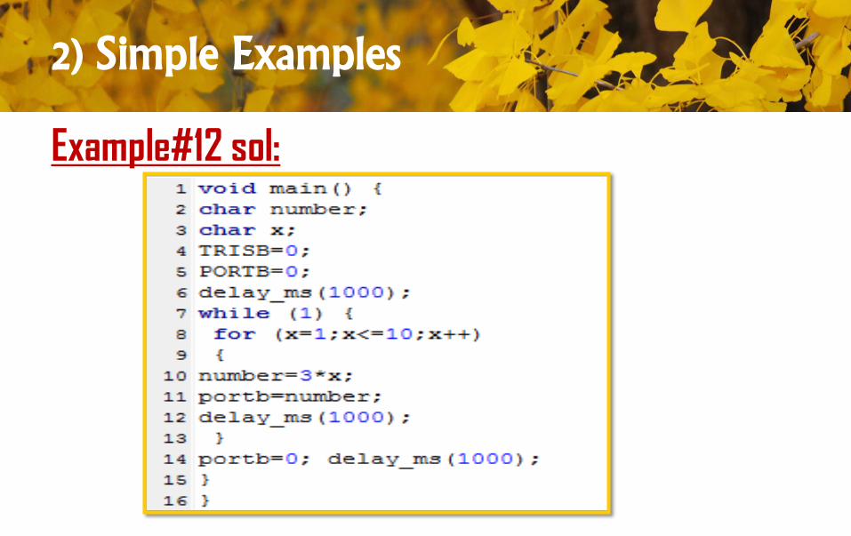
Example#12:Make a multiplication table of 3 in binary, and display the result in portB.
2) Simple Examples
Example#12 sol:
2) Simple Examples
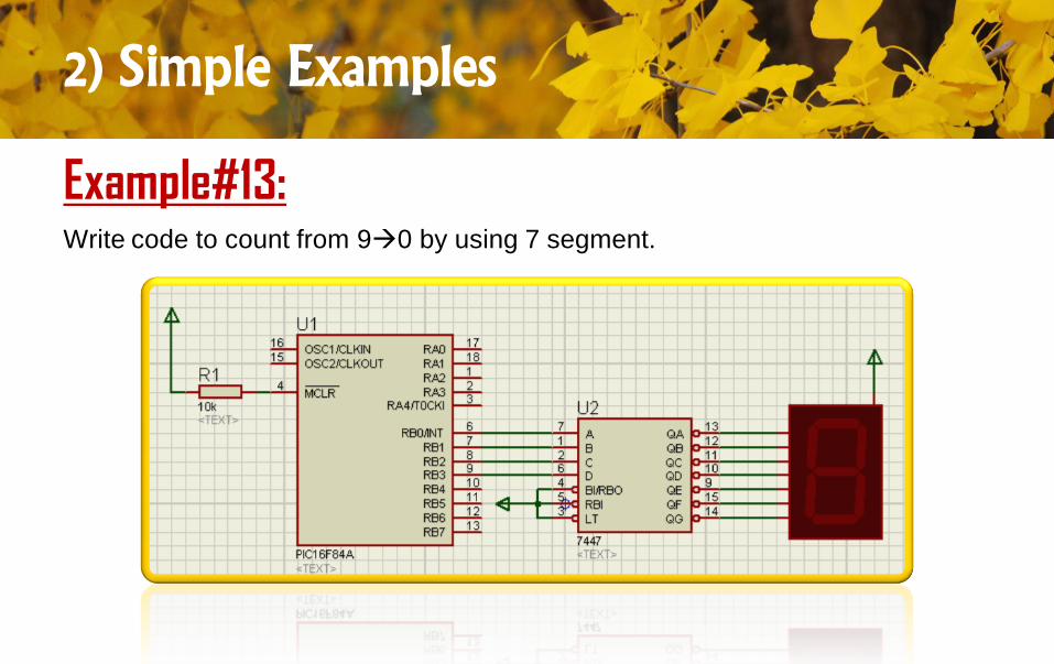
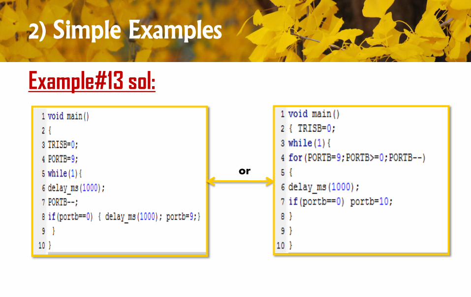
Example#13:Write code to count from 90 by using 7 segment.
2) Simple Examples
Example#13 sol:
or
2) Simple Examples
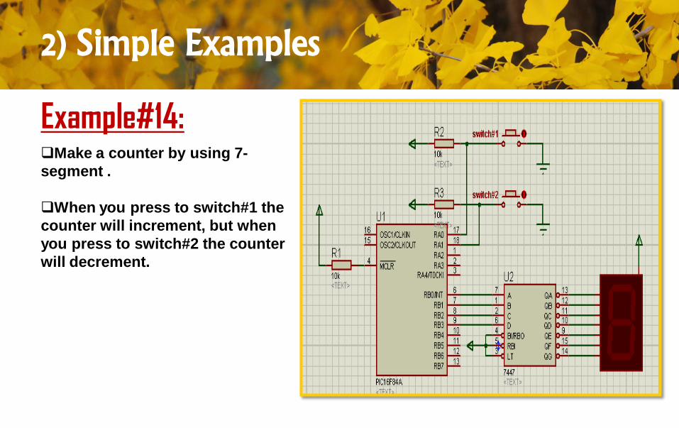
Example#14:Make a counter by using 7-
segment .
When you press to switch#1 the
counter will increment, but when
you press to switch#2 the counter
will decrement.
2) Simple Examples
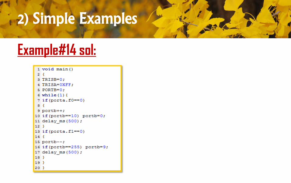
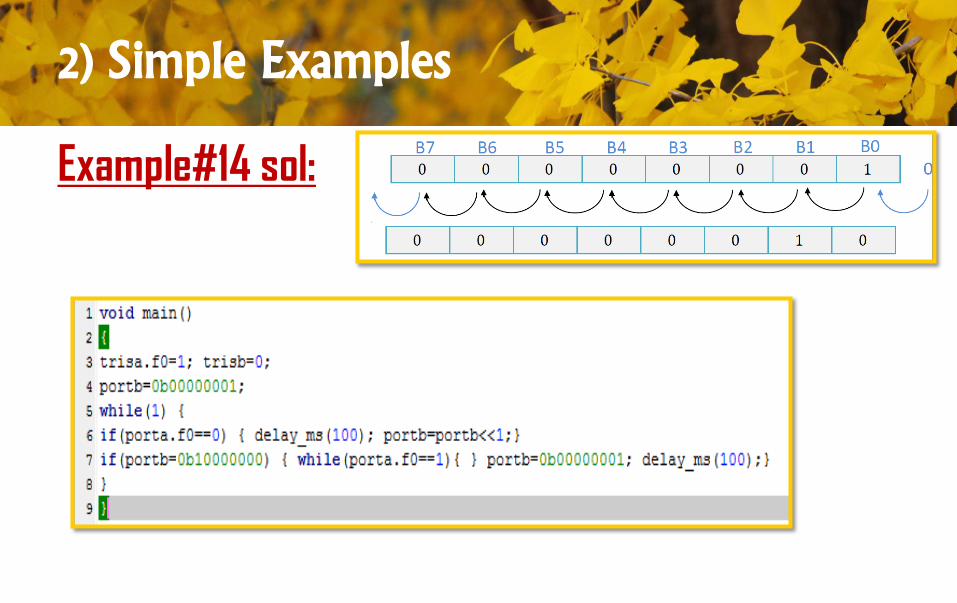
Example#14 sol:
2) Simple Examples
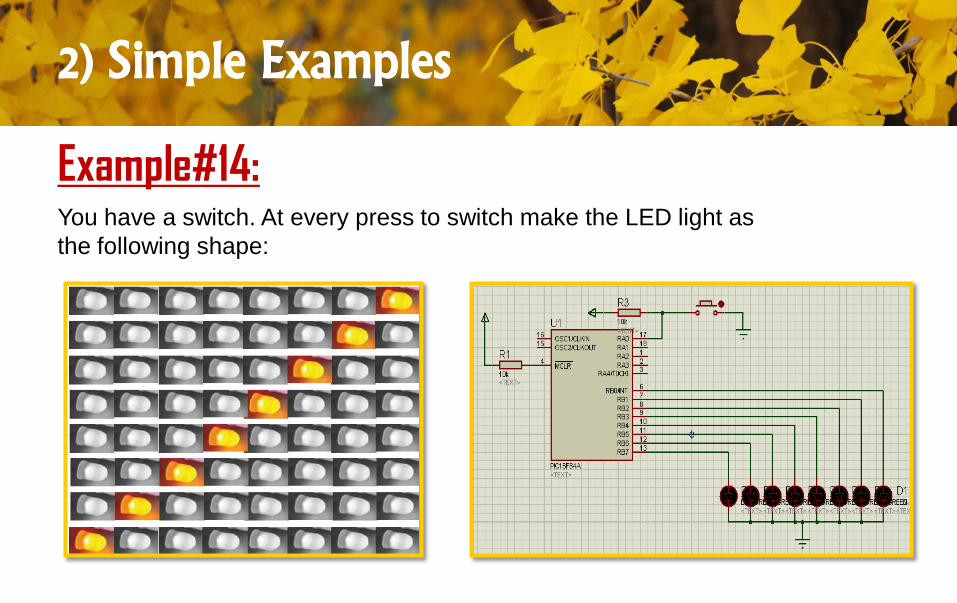
Example#14:You have a switch. At every press to switch make the LED light as
the following shape:
2) Simple Examples
Example#14 sol:
2) Simple Examples
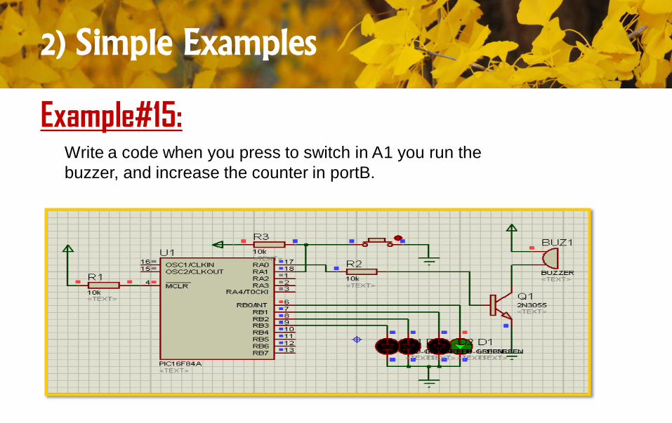
Example#15:Write a code when you press to switch in A1 you run the
buzzer, and increase the counter in portB.
2) Simple Examples
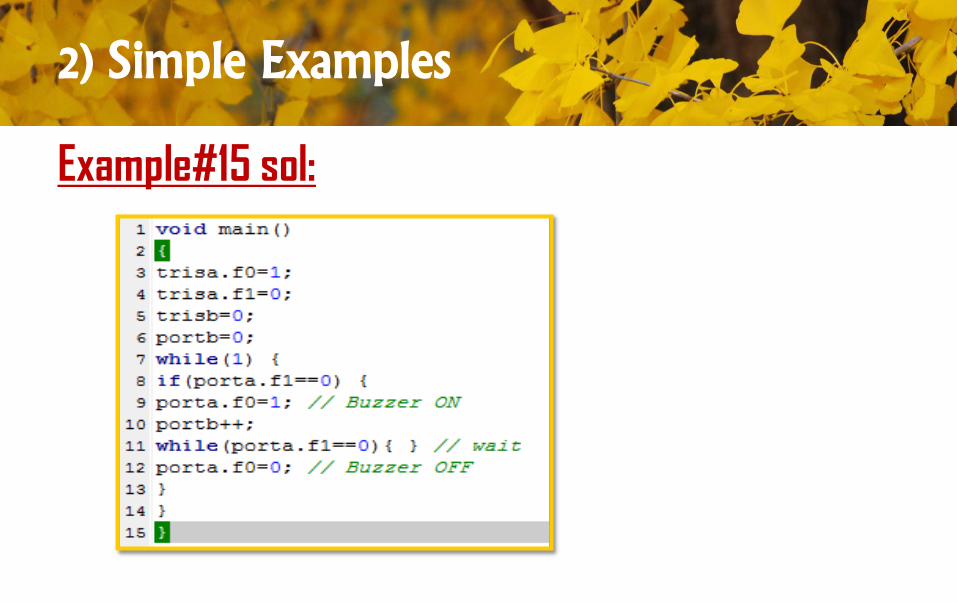
Example#15 sol:
2) Simple Examples
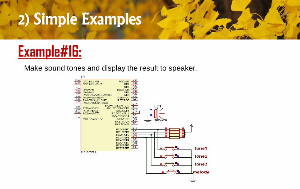
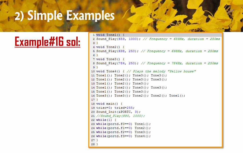
Example#16:Make sound tones and display the result to speaker.
2) Simple Examples
Example#16 sol:
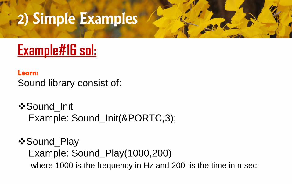
Learn:
Sound library consist of:
Sound_Init
Example: Sound_Init(&PORTC,3);
Sound_Play
Example: Sound_Play(1000,200)
where 1000 is the frequency in Hz and 200 is the time in msec
2) Simple Examples
Example#16 sol:
2) Simple Examples
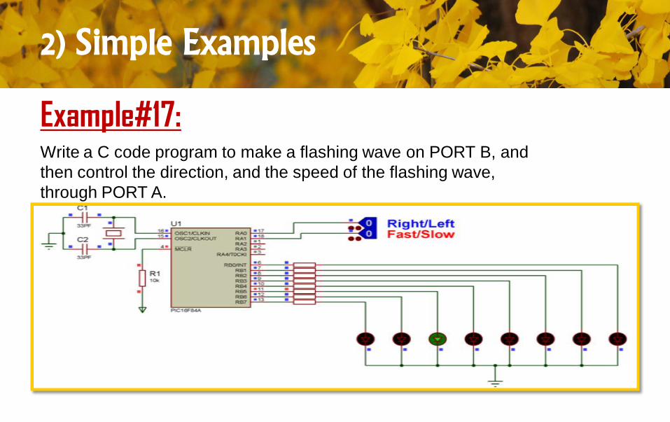
Example#17:Write a C code program to make a flashing wave on PORT B, and
then control the direction, and the speed of the flashing wave,
through PORT A.
2) Simple Examples
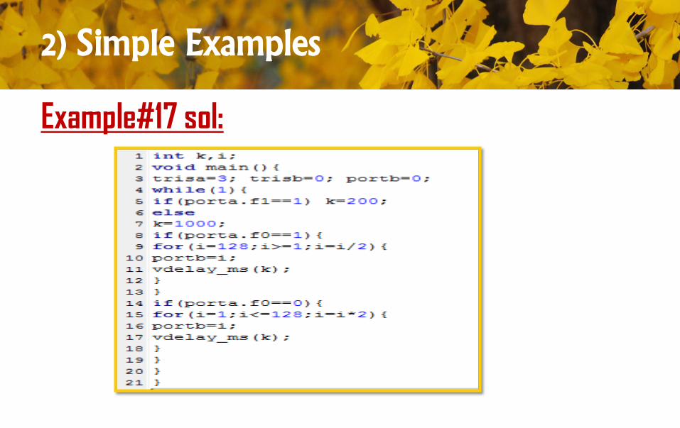
Example#17 sol:
2) Simple Examples
note:
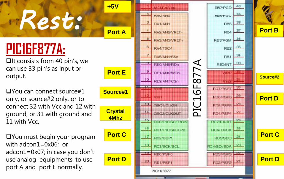
PIC16F877A:It consists from 40 pin’s, we
can use 33 pin’s as input or
output.
You can connect source#1
only, or source#2 only, or to
connect 32 with Vcc and 12 with
ground, or 31 with ground and
11 with Vcc.
You must begin your program
with adcon1=0x06; or
adcon1=0x07; in case you don’t
use analog equipments, to use
port A and port E normally.
Rest:
PIC
16F877A
+5V
Port A
Port E
Source#1
Crystal
4Mhz
Port C
Port D Port D
Port C
Port D
Source#2
Port B
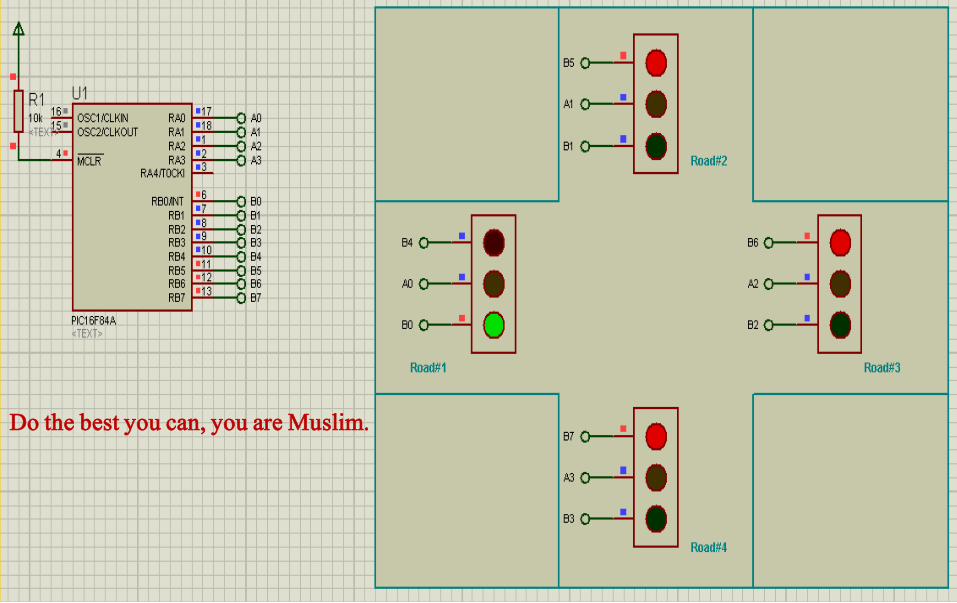
Lab #8Introduction to MikroC Language
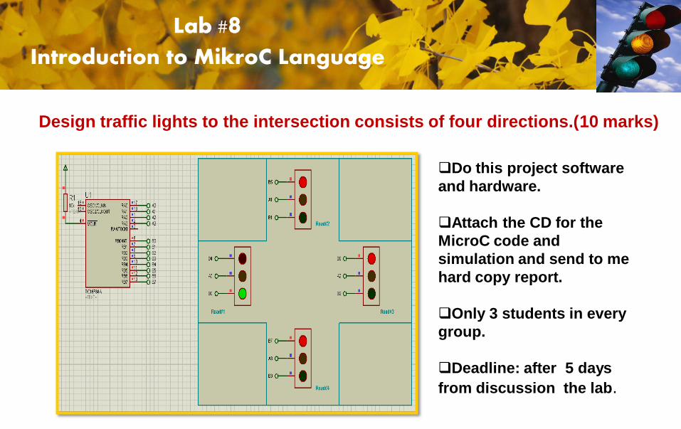
Design traffic lights to the intersection consists of four directions.(10 marks)
Do this project software
and hardware.
Attach the CD for the
MicroC code and
simulation and send to me
hard copy report.
Only 3 students in every
group.
Deadline: after 5 days
from discussion the lab.
Lab #8Introduction to MikroC Language
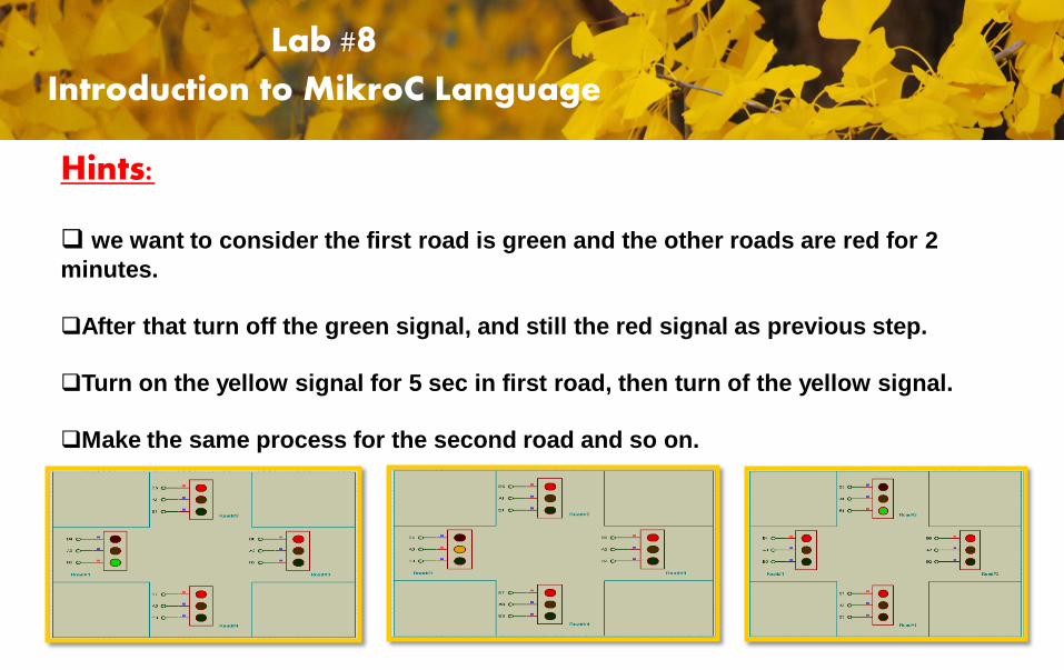
Hints:
we want to consider the first road is green and the other roads are red for 2
minutes.
After that turn off the green signal, and still the red signal as previous step.
Turn on the yellow signal for 5 sec in first road, then turn of the yellow signal.
Make the same process for the second road and so on.
Lab #8Introduction to MikroC Language
Do the best you can, you are Muslim.
Be free to ask any questionEng. Tamar Jomaa

![목 차 - bank1.jinhakapply.combank1.jinhakapply.com/ApplyV8/Public/download.aspx?file=/ApplyV8/... · 화학과 물리화학, 유기및생화학, 무기및분석화학 ... 스마트공장hw솔루션[석사]](https://img.pdfslide.net/doc/110x75/5e12aa02317315437c76cc64/e-bank1-e-ee-oeeef-eeee.jpg)