Embed Size (px)
Citation preview

PIC-P26J50 Proto development board USER’S MANUAL
All boards produced by Olimex LTD are ROHS compliant
Initial release, Januray 2012Designed by OLIMEX Ltd, 2011
OLIMEX© 2012 PIC-P26J50
Disclaimer:
© 2012 Olimex Ltd. Olimex®, logo and combinations thereof, are registered trademarks of Olimex Ltd. Other terms and product names may be trademarks of others.The information in this document is provided in connection with Olimex products. No license, express or implied or otherwise, to any intellectual property right is granted by this document or in connection with the sale of Olimex products. Neither the whole nor any part of the information contained in or the product described in this document may be adapted or reproduced in any material from except with the prior written permission of the copyright holder.The product described in this document is subject to continuous development and improvements. All particulars of the product and its use contained in this document are given by OLIMEX in good faith. However all warranties implied or expressed including but not limited to implied warranties of merchantability or fitness for purpose are excluded.This document is intended only to assist the reader in the use of the product. OLIMEX Ltd. shall not be liable for any loss or damage arising from the use of any information in this document or any error or omission in such information or any incorrect use of the product.
Thank you for purchasing the PIC-P26J50 board manufactured by Olimex!
Page 2 of 19
OLIMEX© 2012 PIC-P26J50
TABLE OF CONTENTS
SECTION 1 OVERVIEW 4
SECTION 2 SETTING UP THE DEVELOPMENT BOARD 5
SECTION 3 PIC-P26J50 BOARD DESCRIPTION 7
SECTION 4 THE PIC18F26J59 MICROCONTROLLER 8
SECTION 5 CONTROL CIRCUITRY 11
SECTION 6 HARDWARE 12
SECTION 7 MEMORY 15
SECTION 8 SCHEMATICS 16
SECTION 9 REVISION HISTORY 19
Page 3 of 19
OLIMEX© 2012 PIC-P26J50
SECTION 1OVERVIEW
Thank you for choosing the PIC-P26J50 development board from Olimex! This document provides a User’s Guide for the Olimex PIC-P26J50 development board. As an overview, this chapter gives the scope of this document and lists the board’s features. The document’s organization is then detailed.
1.1 Scope
The PIC-P26J50 development board enables code development of applications running on the PIC18F26J59 microcontroller. This guide focuses on the PIC-P26J50 board as a development platform for the PIC18F26J59 device.
1.2 Features
• PIC18F26J59 microcontroller with 64K Flash• USB connector• 8 LEDs• Reset button• User button• UEXT connector• mini ICSP/ICD (0,05””) connector for programming• All PIC free ports available on header close to the prototype area• Perfect for hobbyists • Dimensions 61x45 mm (2.4 x 1.77")
1.3 Organization
Each section in this document covers a separate topic, organized as follow:- Section 1 is an overview of the board usage and features- Section 2 provides a guide for quickly setting up the board- Section 3 contains the general board diagram and layout- Section 4 describes the component that is the heart of the board: the PIC18F26J59 microcontroller- Section 5 is an explanation of the control circuitry associated with the microcontroller to reset, power and clock the board- Section 6 covers the connector pinout, peripherals and jumper description- Section 7 shows the memory map- Section 8 provides the schematics- Section 9 contains the revision history
Page 4 of 19
OLIMEX© 2012 PIC-P26J50
SECTION 2SETTING UP THE PIC-P26J50
DEVELOPMENT BOARD
This section helps you set up the PIC-P26J50 development board for the first time.
Please consider first the electrostatic warning to avoid damaging the board, then discover the hardware and software required to operate the board.
The procedure to power up the board is given, and a description of the default board behavior is detailed.
2.1 Electrostatic Warning
The PIC-P26J50 development board is shipped in a protective anti-static package. The board must not be exposed to high electrostatic potentials. A grounding strap or similar protective device should be worn when handling the board. Avoid touching the component pins or any other metallic element.
2.2 Requirements
In order to set up the PIC-P26J50 proto board, the following items are required:
- The PIC-P26J50 development board itself- miniUSB - USB cable
Or
- 3,3 V external power supply
Note: The board is not delivered with an ICSP debugger/programmer, which is needed if you want to reprogram it. Remember that the connector on the board is mini ICSP (6 pin). You may use a pair of the following devices for this purpose:
- Olimex’s PIC-ICD2-POCKET + Olimex’s PIC-ICSP- Olimex’s PIC-KIT3 + Olimex’s PIC-ICSP
Or any compatible PIC programmer with 0,05’’ step ICSP connector.
Also, a host-based software toolchain is required in order to program/debug the PIC-P26J50 board.Our suggestion is to use Microchip’s MPLab IDE.
Page 5 of 19
OLIMEX© 2012 PIC-P26J50
2.3 Powering up the board
The PIC-P26J50 board is self-powered by the miniUSB.
Additionally the board can be powered using the PROTO AREA pads. Provide 3.3 V to the respective pad with the same label. Ground pad is named GND on the opposite side of the 3.3 V.
On powering the board the PWR LED must turn on and the 8 LEDs must start turning on consecutively.
2.4 Prebuilt software
On arrival the board has a simple demo for the LEDS (blinking consecutively) and on pressing BUT they should blink in a different manner.
Page 6 of 19
OLIMEX© 2012 PIC-P26J50
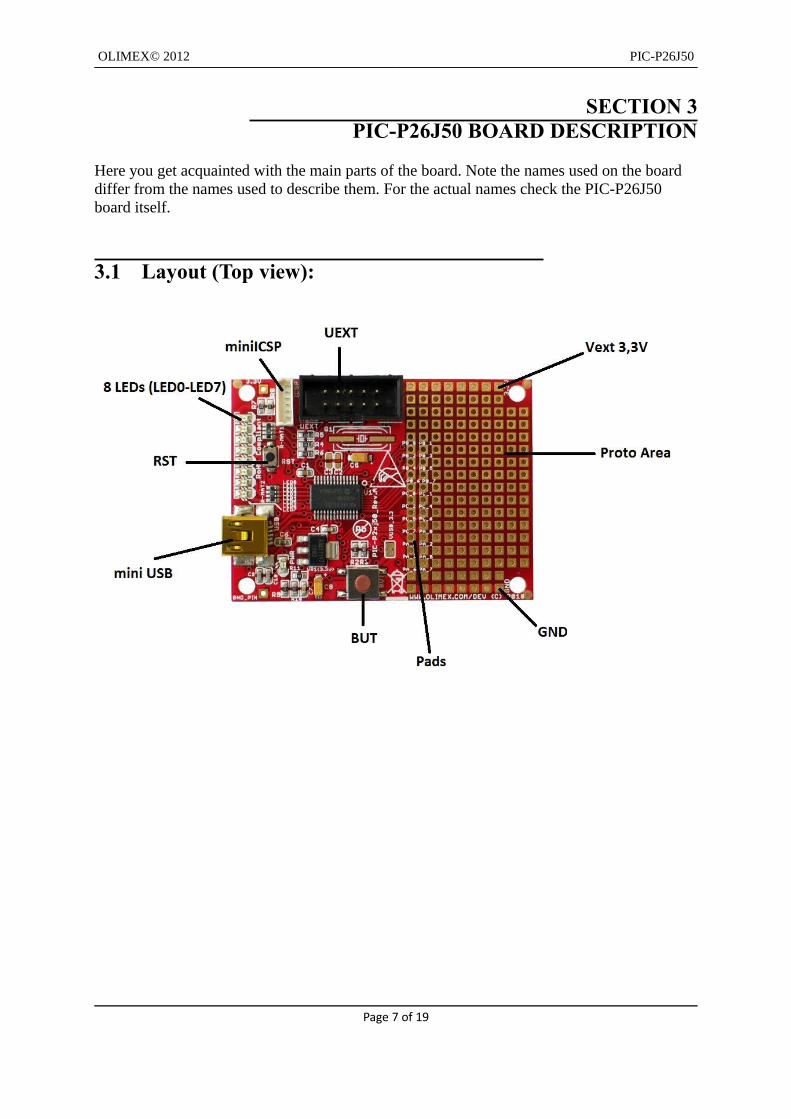
SECTION 3 PIC-P26J50 BOARD DESCRIPTION
Here you get acquainted with the main parts of the board. Note the names used on the board differ from the names used to describe them. For the actual names check the PIC-P26J50 board itself.
3.1 Layout (Top view):
Page 7 of 19

OLIMEX© 2012 PIC-P26J50
SECTION 4THE PIC18F26J50 MICROCONTROLLER
4.1 Features
Power Management Features withnanoWatt XLP™ for Extreme Low-Power:
• Deep Sleep mode: CPU off, Peripherals off,Currents Down to 13 μA and 850 nA with RTCC:
- Able to wake-up on external triggers, programmable WDT or RTCC alarm- Ultra Low-Power Wake-up (ULPWU)
• Sleep mode: CPU off, Peripherals off, SRAM on, Fast Wake-up, Currents Down to 105 μA, Typical
• Idle: CPU off, Peripherals on, Currents Down to 2.3 nA, Typical
• Run: CPU on, Peripherals on, Currents Down to 6.2 nA, Typical
• Timer1 Oscillator w/RTCC: 1 nA, 32 kHz, Typical• Watchdog Timer: 0.8 μA, 2V, Typical
Special Microcontroller Features:• Low-Power, High-Speed CMOS Flash Technology• C Compiler Optimized Architecture for Re-Entrant Code• Priority Levels for Interrupts• Self-Programmable under Software Control• 8 x 8 Single-Cycle Hardware Multiplier• Extended Watchdog Timer (WDT):
- Programmable period from 4 ms to 131s• Single-Supply In-Circuit Serial Programming™(ICSP™) via two pins• In-Circuit Debug (ICD) w/Three Breakpoints via 2 Pins• Operating Voltage Range of 2.0V to 3.6V• On-Chip 2.5V Regulator• Flash Program Memory of 10,000 Erase/Write Cycles Minimum and 20-Year Data
RetentionUniversal Serial Bus (USB) Features
• USB V2.0 Compliant• Full Speed (12 Mbps) and Low Speed (1.5 Mbps)• Supports Control, Interrupt, Isochronous and BulkTransfers• Supports up to 32 Endpoints (16 bidirectional)• USB module can use any RAM Location on the Device as USB Endpoint Buffers• On-Chip USB Transceiver with Crystal-less operation
Flexible Oscillator Structure:• High-Precision Internal Oscillator (±0.15% typ.) for USB• Two External Clock modes, up to 48 MHz (12 MIPS)• Low-Power, 31 kHz Internal RC Oscillator• Tunable Internal Oscillator (31 kHz to 8 MHz, or up to 48 MHz with PLL)• Secondary Oscillator using Timer1 @ 32 kHz
Page 8 of 19

OLIMEX© 2012 PIC-P26J50
• Fail-Safe Clock Monitor:- Allows for safe shutdown if any clock stops
• Two-Speed Oscillator Start-up• Programmable Reference Clock Output Generator
Peripheral Highlights:• Peripheral Pin Select:
- Allows independent I/O mapping of many peripherals- Continuous hardware integrity checking and safety interlocks prevent unintentionalconfiguration changes
• Hardware Real-Time Clock and Calendar (RTCC):- Provides clock, calendar and alarm functions
• High-Current Sink/Source 25 mA/25 mA (PORTB and PORTC)• 5.5V Tolerant Inputs (digital only pins)• Four Programmable External Interrupts• Four Input Change Interrupts• Two Enhanced Capture/Compare/PWM (ECCP) modules:
- One, two or four PWM outputs- Selectable polarity- Programmable dead time- Auto-shutdown and auto-restart- Pulse steering control
• Two Master Synchronous Serial Port (MSSP) modules Supporting Three-Wire SPI (all four modes) and I2C™ Master and Slave modes
• Full-Duplex Master/Slave SPI DMA Engine• 8-Bit Parallel Master Port/Enhanced Parallel Slave Port• Two-Rail – Rail Analog Comparators with Input Multiplexing• 10-Bit, up to 13-Channel Analog-to-Digital (A/D)
Converter module:- Auto-acquisition capability- Conversion available during Sleep- Self-calibration
• High/Low-Voltage Detect module• Charge Time Measurement Unit (CTMU): Supports capacitive touch sensing for touch screens and capacitive switches- Provides a precise resolution time measurement for both flow measurement and simpletemperature sensing• Two Enhanced USART modules:- Supports RS-485, RS-232 and LIN/J2602- Auto-Wake-up on Start bit• Auto-Baud Detect
For comprehensive information on the microcontroller visit the Microchip’s web page for a datasheet.
At the moment of writing the microcontroller datasheet can be found at the following link:
Page 9 of 19

OLIMEX© 2012 PIC-P26J50
http://ww1.microchip.com/downloads/en/DeviceDoc/39931d.pdf
Page 10 of 19

OLIMEX© 2012 PIC-P26J50
SECTION 5CONTROL CIRCUITRY
5.1 Power supply
When PIC-P26J50 is connected via a USB cable to a USB host it will take its 3,3V power supply from the USB host source to power the board.
Additionally the board can be powered using the 3.3V pad and the GND pad on the proto area.
5.2 Reset
PIC-P26J50 reset circuit includes R8 (390Ω), PIC18F26J59 pin 1 (#MCLR/TTL) and a RESET button.
5.3 Clock
Quartz crystal pad is available but a quartz crystal is not mounted! If you want to use the oscillator you have to mount a quartz crystal 12Mhz/12pF on Q1.
Page 11 of 19

OLIMEX© 2012 PIC-P26J50
SECTION 6HARDWARE
6.1 Mini ICSP
The mini ICSP connector provides the interface for In-Circuit-Serial-Programming. The step between its pins is 0.05".
Pin # Signal Name
1 RSTN/Vpp
2 +3.3V
3 GND
4 PGD
5 PGC
6 Not connected
6.2 UEXT
PIC32-PINGUINO-MICRO board has UEXT connector and can interface Olimex's UEXT modules.
For more information on UEXT please visit:
http://www.olimex.com/dev/OTHER/UEXT.pdf
Pin # Signal Name
1 +3.3V
2 GND
3 TXD
4 RXD
5 SCL
6 SDA
Page 12 of 19

OLIMEX© 2012 PIC-P26J50
7 MISO
8 MOSI
9 SCK
10 CS
6.3 Pads on the proto area
For your convenience the pads are named individually near each of them. Please take extra care about the numbering.
All pads are near the PIC18, except for GND and 3,3V pads.
PAD # Signal Name
PB_0 USER (RB0/AN12/INT0/RP3)
PB_1 SCK
PB_2 MISO
PB_3 MOSI
PB_4 SCL
PB_5 SDA
PB_6 PGC
PB_7 PGD
PC_0 LED6
PC_1 LED5
PC_2 LED4
PC_4 D-
PC_5 D+
PC_6 TXD
PC_7 RXD
PA_0 LED0
PA_1 LED1
PA_2 LED2
PA_3 LED3
PA_5 LED7
PA_6 OSC2/CLK0 (to quartz pad)
Page 13 of 19
OLIMEX© 2012 PIC-P26J50
PA_7 Vss OSC (quarz pad)
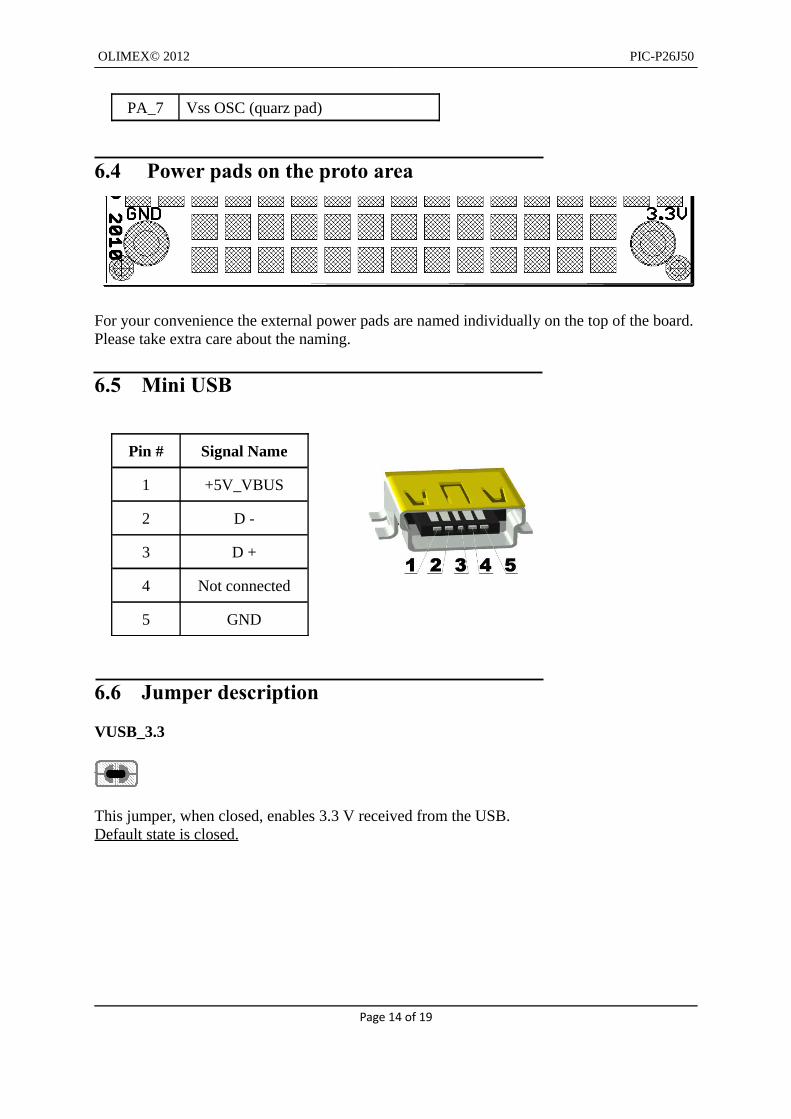
6.4 Power pads on the proto area
For your convenience the external power pads are named individually on the top of the board. Please take extra care about the naming.
6.5 Mini USB
Pin # Signal Name
1 +5V_VBUS
2 D -
3 D +
4 Not connected
5 GND
6.6 Jumper description
VUSB_3.3
This jumper, when closed, enables 3.3 V received from the USB.Default state is closed.
Page 14 of 19

OLIMEX© 2012 PIC-P26J50
SECTION 7MEMORY
7.1 Memory map
Page 15 of 19
OLIMEX© 2012 PIC-P26J50
SECTION 8SCHEMATICS
8.1 Eagle schematic
PIC-P26J50 schematic is visible for reference here. You can also find them on separated in the web page for PIC-P26J50 on our site: http://www.olimex.com/dev/pic-p26j50.html. They are located in HARDWARE section.
The EAGLE schematic is situated on the next page for quicker reference.
Page 16 of 19

OLIMEX© 2012 PIC-P26J50
Page 17 of 19
OLIMEX© 2012 PIC-P26J50
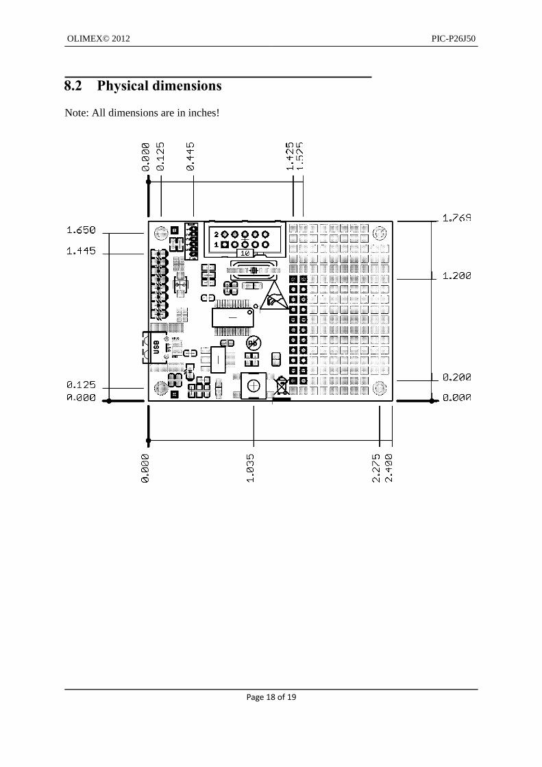
8.2 Physical dimensions
Note: All dimensions are in inches!
Page 18 of 19

OLIMEX© 2012 PIC-P26J50
SECTION 9REVISION HISTORY
9.1 Document revision
Revision Changes Modified Pages
A Initial Creation All
9.2 Web page of your deviceThe web page you can visit for more info on your device is http://www.olimex.com/dev/pic-p26j50.html. There you can find more info and some examples.
ORDER CODES:
PIC-P26J50 - completely assembled and tested with PIC18F26J50 on board
PIC-ICD2-POCKET + PIC-ICSP - for custom programming/debuggingPIC-KIT3 + PIC-ICSP - for custom programming/debuggingUSB-MINI-CABLE - USBmini to USB-A cable
How to order?
You can order to us directly or by any of our distributors. Check our webpage http://www.olimex.com/ for more info.
Page 19 of 19