Embed Size (px)
Citation preview
PIC32-T795 development boardUSER’S MANUAL
Revision F, August 2014Designed by OLIMEX Ltd, 2012
All boards produced by Olimex LTD are ROHS compliant
OLIMEX© 2012 PIC32-T795 user's manual
DISCLAIMER
© 2013 Olimex Ltd. Olimex®, logo and combinations thereof, are registered trademarks of Olimex Ltd.Other product names may be trademarks of others and the rights belong to their respective owners.
The information in this document is provided in connection with Olimex products. No license, expressor implied or otherwise, to any intellectual property right is granted by this document or in connectionwith the sale of Olimex products.
This work is licensed under the Creative Commons Attribution-ShareAlike 3.0 Unported License. To view acopy of this license, visit http://www.creativecommons.org/licenses/by-sa/3.0/.
This hardware design by Olimex LTD is licensed under a Creative Commons Attribution-ShareAlike 3.0Unported License.
The software is released under GPL.
It is possible that the pictures in this manual differ from the latest revision of the board.
The product described in this document is subject to continuous development and improvements. Allparticulars of the product and its use contained in this document are given by OLIMEX in good faith.However all warranties implied or expressed including but not limited to implied warranties ofmerchantability or fitness for purpose are excluded. This document is intended only to assist the reader in theuse of the product. OLIMEX Ltd. shall not be liable for any loss or damage arising from the use of anyinformation in this document or any error or omission in such information or any incorrect use of theproduct.
This evaluation board/kit is intended for use for engineering development, demonstration, or evaluationpurposes only and is not considered by OLIMEX to be a finished end-product fit for general consumer use.Persons handling the product must have electronics training and observe good engineering practicestandards. As such, the goods being provided are not intended to be complete in terms of required design-,marketing-, and/or manufacturing-related protective considerations, including product safety andenvironmental measures typically found in end products that incorporate such semiconductor components orcircuit boards.
Olimex currently deals with a variety of customers for products, and therefore our arrangement with the useris not exclusive. Olimex assumes no liability for applications assistance, customer product design, softwareperformance, or infringement of patents or services described herein.
THERE IS NO WARRANTY FOR THE DESIGN MATERIALS AND THE COMPONENTS USED TO CREATE PIC32-T795. THEY ARE CONSIDERED SUITABLE ONLY FOR PIC32-T795.
Page 2 of 26
OLIMEX© 2012 PIC32-T795 user's manual
Table of Contents
DISCLAIMER ............................................................................................................. 2CHAPTER 1 OVERVIEW ......................................................................................... 5
1. Introduction to the chapter ....................................................................................................... 5
1.1 Features ..................................................................................................................................... 51.2 Organization ............................................................................................................................. 5
CHAPTER 2 SETTING UP THE PIC32-T795 BOARD ......................................... 72. Introduction to the chapter ....................................................................................................... 7
2.1 Electrostatic warning ............................................................................................................... 72.2 Requirements ........................................................................................................................... 7
2.3 Powering the board .................................................................................................................. 82.4 Prebuilt software ...................................................................................................................... 8
CHAPTER 3 PIC32-T795 BOARD DESCRIPTION ............................................... 93. Introduction to the chapter ....................................................................................................... 9
3.1 Layout (top view) ..................................................................................................................... 93.2 Layout (bottom view) ............................................................................................................. 10
CHAPTER 4 THE PIC32MX795F512H MICROCONTROLLER ...................... 114. Introduction to the chapter ..................................................................................................... 11
4.1 The microcontroller ............................................................................................................... 11
CHAPTER 5 CONTROL CIRCUITY .................................................................... 135. Introduction to the chapter ..................................................................................................... 135.1 Reset ........................................................................................................................................ 13
5.2 Clock ....................................................................................................................................... 13
CHAPTER 6 HARDWARE ...................................................................................... 146. Introduction to the chapter ..................................................................................................... 146.1 ICSP connector ....................................................................................................................... 14
6.2 UEXT ...................................................................................................................................... 146.3 Pinout of the row headers at the bottom .............................................................................. 15
6.4 USB_OTG ............................................................................................................................... 166.5 Jumper description ................................................................................................................ 17
6.6 Additional hardware components ........................................................................................ 18
CHAPTER 7 MEMORY ........................................................................................... 197. Introduction to the chapter ..................................................................................................... 197.1 Block diagram of the processor ............................................................................................ 19
7.2 Memory map .......................................................................................................................... 20
CHAPTER 8 SCHEMATICS ................................................................................... 218. Introduction to the chapter ..................................................................................................... 21
Page 3 of 26
OLIMEX© 2012 PIC32-T795 user's manual
8.1 Eagle schematic ...................................................................................................................... 218.2 Physical dimensions ............................................................................................................... 23
CHAPTER 9 REVISION HISTORY ....................................................................... 249. Introduction to the chapter ..................................................................................................... 24
9.1 Document revision ................................................................................................................. 249.2 Web page of your device ........................................................................................................ 25
9.3 Product support ..................................................................................................................... 26
Page 4 of 26
OLIMEX© 2013 PIC32-T795 user's manual
CHAPTER 1 OVERVIEW
1. Introduction to the chapter
Thank you for choosing the PIC32-T795 development board from Olimex! This document providesa User’s Guide for the Olimex PIC32-T795 development board. As an overview, this chapter gives the scope of this document and lists the board’s features. The document’s organization is then detailed.
The PIC32-T795 development board enables code development of applications running on the PIC32MX795F512H microcontroller, manufactured by Microchip.
1.1 Features
• PIC32MX795F512H 80 Mhz microcontroller 512KB Flash 128KB RAM , 3x SPI, 4x I2C, USB OTG, 1MSPS ADC, PMP 80Mhz digital capture, 5 TIMERS/CCP, 53 GPIOs
• USB-OTG supporting both Host and Device functions and allows the implementation of Google Android ADK
• Comes programmed with Duinomite bootloader – even if you lack programmer tool you canprogram the board using the mini USB
• UEXT connector which allows many existing modules like RF, ZIGBEE, GSM, GPS to be connected
• two LEDs
• one BUTTONs
• RESET button
• mini USB connector is used which is common and used in most cell phones, so you do not have to buy other cables
• all PIC ports available on 0.1" connectors
• ICSP connector allows programming with PIC-KIT3
• Dimensions 87×54 mm (3.4×2.12")
1.2 Organization
Each section in this document covers a separate topic, organized as follow:
– Chapter 1 is an overview of the board usage and features
– Chapter 2 provides a guide for quickly setting up the board
– Chapter 3 contains the general board diagram and layout
– Chapter 4 describes the component that is the heart of the board: the PIC32MX795F512H microcontroller
– Chapter 5 is an explanation of the control circuitry associated with the microcontroller to reset. Also shows the clocks on the board
Page 5 of 26
OLIMEX© 2013 PIC32-T795 user's manual
– Chapter 6 covers the connector pinout, peripherals and jumper description
– Chapter 7 shows the memory map
– Chapter 8 provides the schematics
– Chapter 9 contains the revision history
Page 6 of 26

OLIMEX© 2013 PIC32-T795 user's manual
CHAPTER 2 SETTING UP THE PIC32-T795 BOARD
2. Introduction to the chapter
This section helps you set up the PIC32-T795 development board for the first time.
Please consider first the electrostatic warning to avoid damaging the board, then discover the hardware and software required to operate the board.
The procedure to power up the board is given, and a description of the default board behavior is detailed.
2.1 Electrostatic warning
PIC32-T795 is shipped in a protective anti-static package. The board must not be exposed to high electrostatic potentials. A grounding strap or similar protective device should be worn when handling the board. Avoid touching the component pins or any other metallic element.
2.2 Requirements
In order to set up the PIC32-T795, the following items are required:
- miniUSB to USB A cable
- Computer work station
Highly recommended items:
- Breadboard https://www.olimex.com/Products/Duino/Breadboarding/BREADBOARD-1/, https://www.olimex.com/Products/Duino/Breadboarding/BREADBOARD-MINI/
- PIC32 compatible programmer/debugger. You can use our PIC-KIT3 for programming/debugging https://www.olimex.com/Products/PIC/Programmers/PIC-KIT3/
- Jumper wires for testing https://www.olimex.com/Products/Duino/Breadboarding/BREADBOARD-MINI/
The breadboard helps you use the free pins at the bottom of the board with jumper wires without soldering. Also makes applying external supply easier.
Additionally a host-based software toolchain is required in order to program/debug the PIC32-T795board.
Page 7 of 26

OLIMEX© 2013 PIC32-T795 user's manual
2.3 Powering the board
The board is powered either by the mini USB or by the SUPPLY1 or SUPPLY2 line(when the boardis mounted on the breadboard you might use the VCC and the VDD breadboard bus).
On powering the board PWR and LED2 LEDS turn on.
The board comes with preloaded Duinomite bootloader. For more information on Duinomite check the following links and documents:
http://www.duinomite.com/
https://www.olimex.com/Products/Duino/Duinomite/DUINOMITE-MEGA/
If you don't remove the bootlader the board comes with, when connected via the USB OTG the device should be recognized as a COMx. If it doesn't get recognized this means you lack the driver for your operating system.
2.4 Prebuilt software
On arrival the board has a Duinomite bootloader installed.
Connect the board to the computer work station (e.g. PC) via the USB OTG. Open the device manager and check which COM port the device initialized at. Launch your favorite terminal program at the COM port found at 115200 baud. Press “Enter” on your keyboard. Write “setup” command in the terminal.
For more comprehensive set of example and notes on the MM-Basic check the user manuals of the Duinomite boards.
The board can be relatively easy configured for use with Piunguino IDE also. You would need to change the SMT jumper at the bottom of the board from RD8 (default) position to RD0. This is required since Pinguino and Duinomite bootloaders use different pins for the button required to enter bootloader mode. All files that might be required to change to Pinguino IDE are available at the PIC32-T795H's website.
Page 8 of 26
OLIMEX© 2013 PIC32-T795 user's manual
CHAPTER 3 PIC32-T795 BOARD DESCRIPTION
3. Introduction to the chapter
Here you get acquainted with the main parts of the board. Note the names used on the board differ from the names used to describe them. For the actual names check the PIC32-T795 board itself.
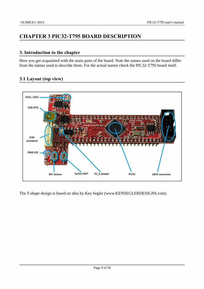
3.1 Layout (top view)
The T-shape design is based on idea by Ken Segler (www.KENSEGLERDESIGNS.com).
Page 9 of 26
OLIMEX© 2013 PIC32-T795 user's manual
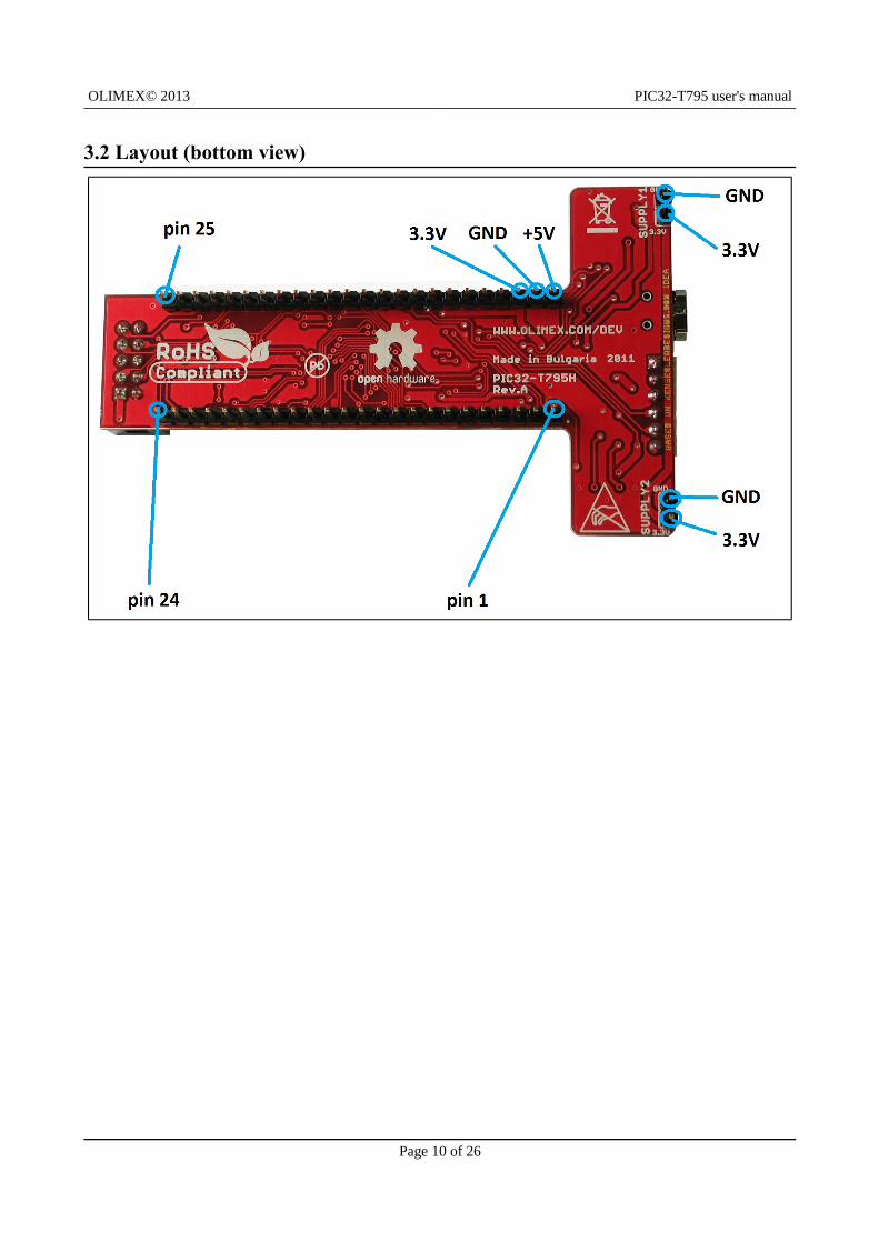
3.2 Layout (bottom view)
Page 10 of 26
OLIMEX© 2013 PIC32-T795 user's manual
CHAPTER 4 THE PIC32MX795F512H MICROCONTROLLER
4. Introduction to the chapter
In this chapter is located the information about the heart of PIC32-T795 – its microcontroller. The information is a modified version of the datasheet provided by its manufacturers.
4.1 The microcontroller
PIC32-T795 board uses PIC32MX795F512H from Microchip Technology with these features:
High-Performance 32-bit RISC CPU:
MIPS32® M4K® 32-bit core with 5-stage pipeline
80 MHz maximum frequency
1.56 DMIPS/MHz (Dhrystone 2.1) performance at zero Wait state Flash access
Single-cycle multiply and high-performance divide unit
MIPS16e™ mode for up to 40% smaller code size
Two sets of 32 core register files (32-bit) to reduce interrupt latency
Prefetch Cache module to speed execution from Flash
Microcontroller Features:
Operating voltage range of 2.3V to 3.6V
512K Flash memory (plus an additional 12 KB of Boot Flash)
128K SRAM memory
Pin-compatible with most PIC24/dsPIC® DSC devices
Multiple power management modes
Multiple interrupt vectors with individually programmable priority
Fail-Safe Clock Monitor mode
Configurable Watchdog Timer with on-chip Low-Power RC oscillator for reliable operationPeripheral Features:
Atomic SET, CLEAR and INVERT operation on select peripheral registers
8-channels of hardware DMA with automatic data size detection
USB 2.0-compliant full-speed device and On-The-Go (OTG) controller:
Dedicated DMA channels
10/100 Mbps Ethernet MAC with MII and RMII interface:
Dedicated DMA channels
CAN module:
2.0B Active with DeviceNet™ addressing support
Dedicated DMA channels
Page 11 of 26
OLIMEX© 2013 PIC32-T795 user's manual
3 MHz to 25 MHz crystal oscillator
Internal 8 MHz and 32 kHz oscillators
Six UART modules with:
RS-232, RS-485 and LIN 1.2 support
IrDA® with on-chip hardware encoder and decoder
Four SPI modules
Five I2C™ modules
Separate PLLs for CPU and USB clocks
Parallel Master and Slave Port (PMP/PSP) with 8-bit and 16-bit data, and up to 16 address lines
Hardware Real-Time Clock and Calendar (RTCC)
Five 16-bit Timers/Counters (two 16-bit pairs combine to create two 32-bit timers)
Five Capture inputs
Five Compare/PWM outputs
Five external interrupt pins
High-speed I/O pins capable of toggling at up to 80 MHz
High-current sink/source (18 mA/18 mA) on all I/O pins
Configurable open-drain output on digital I/O pins Debug Features:
Two programming and debugging Interfaces:
2-wire interface with unintrusive access and real-time data exchange with application
4-wire MIPS® standard enhanced Joint Test Action Group (JTAG) interface
Unintrusive hardware-based instruction trace
IEEE Standard 1149.2 compatible (JTAG) boundary scan Analogue Features:
16-channel, 10-bit Analog-to-Digital Converter:
1 Msps conversion rate
Conversion available during Sleep and Idle
Two Analog Comparators
5V tolerant input pins (digital pins only)
Page 12 of 26
OLIMEX© 2013 PIC32-T795 user's manual
CHAPTER 5 CONTROL CIRCUITY
5. Introduction to the chapter
Here you can find information about reset circuit and quartz crystal locations.
5.1 Reset
PIC32-T795 reset circuit includes R13 (4.7 kΩ), R14 (330 Ω), R66(560 Ω), C21(100 nF), D3 (1N4148), PIC32MX795F512H pin 7 (#MCLR) and a RESET button. The RESET is also connected to the ICSP pin 1.
5.2 Clock
8 MHz quartz crystal Q1 is connected to pins 39 and 40 of the processor.
Real time clock (RTC) Q2 is found at pins 47 and 48 of the processor.
IMPORTANT: If the board has a quartz crystal rotated at 45 degrees relative to the pads provided
do not panic. This is normal. We have two types of such crystals – one of them requires 4 pads, the
other only 2 pads. That is why we have provided 4 pads to be able to fit both crystals. All boards
Olimex manufactures pass automatized optical inspection after assembly and obvious
misplacements like these are impossible to occur.
Page 13 of 26
OLIMEX© 2013 PIC32-T795 user's manual
CHAPTER 6 HARDWARE
6. Introduction to the chapter
In this chapter are presented the connectors that can be found on the board all together with their pinout. Jumpers functions are described. Notes and info on specific peripherals are presented. Notesregarding the interfaces are given.
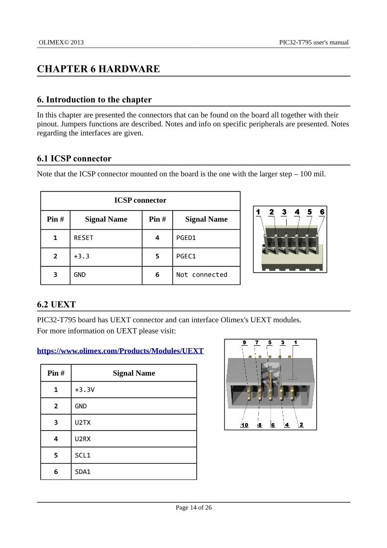
6.1 ICSP connector
Note that the ICSP connector mounted on the board is the one with the larger step – 100 mil.
ICSP connector
Pin # Signal Name Pin # Signal Name
1 RESET 4 PGED1
2 +3.3 5 PGEC1
3 GND 6 Not connected
6.2 UEXT
PIC32-T795 board has UEXT connector and can interface Olimex's UEXT modules.
For more information on UEXT please visit:
https://www.olimex.com/Products/Modules/UEXT
Pin # Signal Name
1 +3.3V
2 GND
3 U2TX
4 U2RX
5 SCL1
6 SDA1
Page 14 of 26
OLIMEX© 2013 PIC32-T795 user's manual
7 MISO
8 MOSI
9 SCK
10 #CS
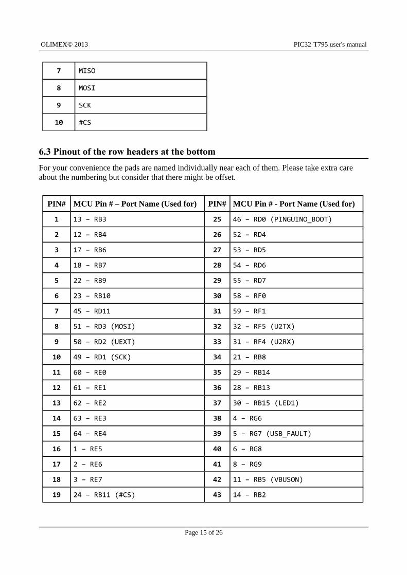
6.3 Pinout of the row headers at the bottom
For your convenience the pads are named individually near each of them. Please take extra care about the numbering but consider that there might be offset.
PIN# MCU Pin # – Port Name (Used for) PIN# MCU Pin # - Port Name (Used for)
1 13 – RB3 25 46 – RD0 (PINGUINO_BOOT)
2 12 – RB4 26 52 – RD4
3 17 – RB6 27 53 – RD5
4 18 – RB7 28 54 – RD6
5 22 – RB9 29 55 – RD7
6 23 – RB10 30 58 – RF0
7 45 – RD11 31 59 – RF1
8 51 – RD3 (MOSI) 32 32 – RF5 (U2TX)
9 50 – RD2 (UEXT) 33 31 – RF4 (U2RX)
10 49 – RD1 (SCK) 34 21 – RB8
11 60 – RE0 35 29 – RB14
12 61 – RE1 36 28 – RB13
13 62 – RE2 37 30 – RB15 (LED1)
14 63 – RE3 38 4 – RG6
15 64 – RE4 39 5 – RG7 (USB_FAULT)
16 1 – RE5 40 6 – RG8
17 2 – RE6 41 8 – RG9
18 3 – RE7 42 11 – RB5 (VBUSON)
19 24 – RB11 (#CS) 43 14 – RB2
Page 15 of 26
OLIMEX© 2013 PIC32-T795 user's manual
20 27 – RB12 (LED2) 44 15 – RB1 (PGEC1)
21 33 – RF3 (USB_ID) 45 16 – RB0 (PGED1)
22 42 – RD8 (DUINOMITE_BOOT) 3.3V 3.3V
23 43 – RD9 (SDA1) GND GND
24 44 – RD10 (SCL1)+5V_EXT +5V
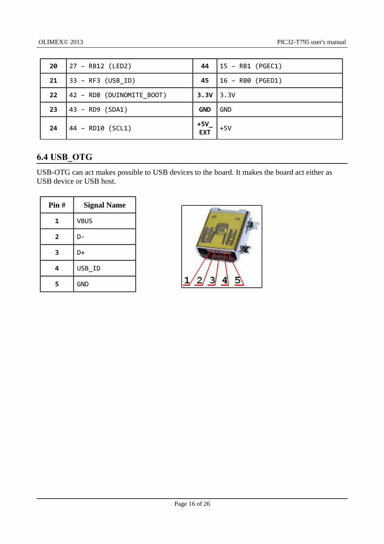
6.4 USB_OTG
USB-OTG can act makes possible to USB devices to the board. It makes the board act either as USB device or USB host.
Pin # Signal Name
1 VBUS
2 D-
3 D+
4 USB_ID
5 GND
Page 16 of 26
OLIMEX© 2013 PIC32-T795 user's manual
6.5 Jumper description
Most of the jumper configurations are printed with white print on the PCB for your convenience. Note that all of the jumpers on the board are SMD type. You will need basic soldering skills to be able to close those jumpers. If you have to separate already connected ones unsolder them and if needed cut the wire between the pads with cutter knife.
5V_E (optional)
In first few revisions of the board this jumper (when closed) was meant to enable 5V to the SUPPLY1 and SUPPLY2 lines (by default 3.3V) when closed but it also raised the processor's voltage way beyond the acceptable levels so the jumper was removed in latest revisions.
Please do not close 5V_E or you might damage the microcontroller on your PIC32-T795.
Default state is open.
RD8/RD0
Changes the default boot pin. If RD8 is selected starts with Duinomite bootloader. If RD0 is selected Pinguino bootloader.
The difference between the two bootloaders is the processor pin used for the button. Duinomite bootloader may be found at the Duinomite repository and Pinguino bootloader may be found in the Pinguino IDE folders.
Default positions is RD8.
EE_SCL1_E & EE_SDA1_E
These jumpers must be moved together. When open disconnect the EEPROM. If you use UEXT connector for something different than I2C better cut both these jumpers.
Default state is closed.
Page 17 of 26
OLIMEX© 2013 PIC32-T795 user's manual
6.6 Additional hardware components
The components below are mounted on PIC32-T795 but are not discussed above. They are listed here for completeness:
user button + RST button
2 user LEDs + PWR LED
Page 18 of 26
OLIMEX© 2013 PIC32-T795 user's manual
CHAPTER 7 MEMORY
7. Introduction to the chapter
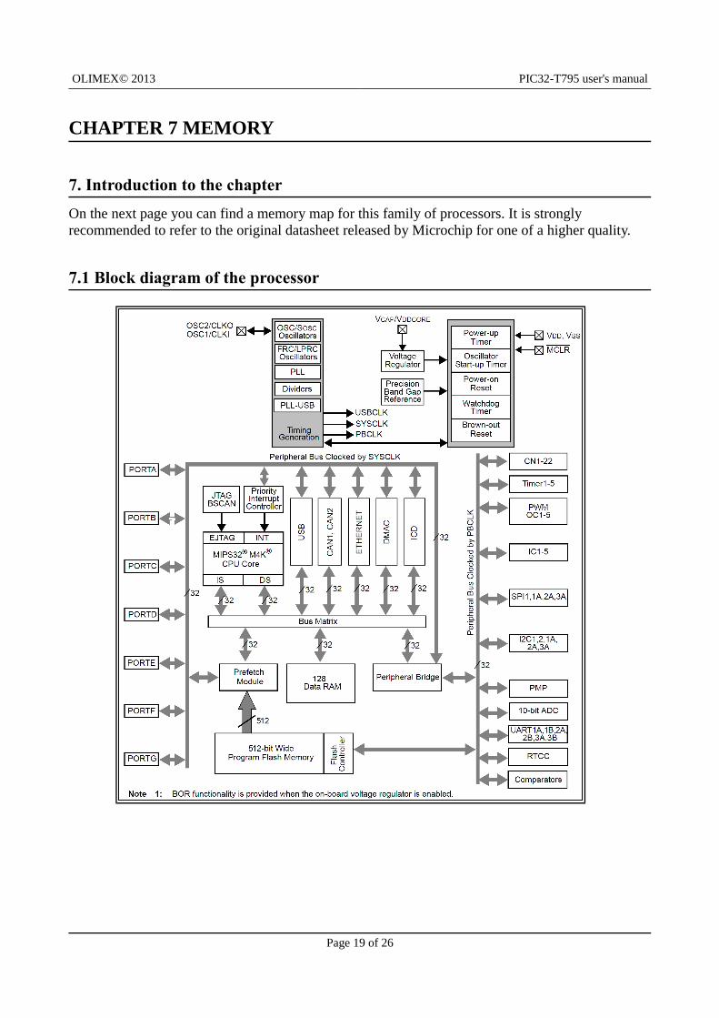
On the next page you can find a memory map for this family of processors. It is strongly recommended to refer to the original datasheet released by Microchip for one of a higher quality.
7.1 Block diagram of the processor
Page 19 of 26
OLIMEX© 2013 PIC32-T795 user's manual
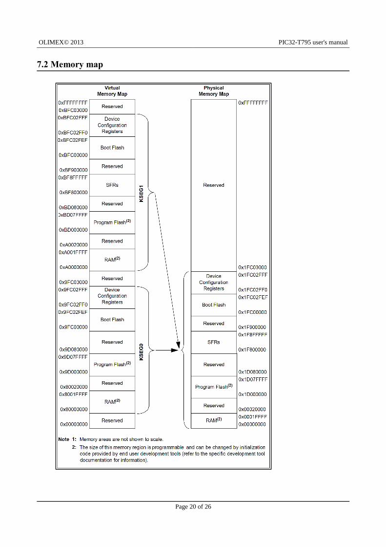
7.2 Memory map
Page 20 of 26
OLIMEX© 2013 PIC32-T795 user's manual
CHAPTER 8 SCHEMATICS
8. Introduction to the chapter
In this chapter are located the schematics describing logically and physically PIC32-T795.
8.1 Eagle schematic
PIC32-T795 schematic is visible for reference here. You can also find them on the web page for PIC32-T795 at our site: https://www.olimex.com/Products/Duino/PIC32/PIC32-T795/. They are located in HARDWARE section.
The EAGLE schematic is situated on the next page for quicker reference.
Page 21 of 26

OLIMEX© 2012 PIC32-T795 User's Manual
Page 22 of 26
Released under Creative Commons Attribution-Share Alike 3.0 United States License
PIC32-T795H Rev.BDesigned by: WWW.OLIMEX.COM/DEVBASED ON WWW.KENSEGLERDESIGNS.COM IDEA
open
T11
07A
(6x3
.8x2
.5m
m)
10uF
/6.3
V
100nF 100nF 100nF 100nF100nF
27pF
27pF
27pF
27pF10
0n
F
100nF100nF 2.2uF 100nF10nF
10nF
10
uF
/6.3
V
100nF 10
uF
/6.3
V
10
uF
/6.3
V
4.7nF
100nF
1N5819S/SS14
1N5819S/SS14
1N4148/mini-mel f
close
close
CON6WF6S
22uH/10%/5mA
LED0603/GREEN LED0603/YELLOW
+5V
+5V
LE
D0
60
3/R
ED
Q8.000MHz/20pF
QCT32768(2x6)/6pF
10
k1
0k
33R
4.7k 4.7k 10k
330R1M/1%
100k/1%
390R/1%
240R/1%
0R(NA)
4.7k
330R
4.7k
330R
330R
NA(4.7k) NA(4.7k) 1k 1k
1k
T11
07A
(6x3
.8x2
.5m
m)
HN
1x2
HN
1x2
DTC114YKA
PIC32MX795F512H-80I/PT
MIC2075YM
24LC256-I/SN
BH10S
USB-OTG
3.3V
3.3V
3.3V
+5V_EXT
+5V_EXT
3.3V
3.3V
3.3V
3.3V3.3V 3.3V 3.3V
3.3V 3.3V
3.3V
3.3V3.3V AVCC
3.3V_AVCC
LM1117IMPX-ADJ
#CS
#CS
+5V
1.8V_CORE
D+ D+D- D-
DUINOMITE_BOOT
DUINOMITE_BOOT
LED1
LED1
LED1
LED2
LED2
MISO
MISO
MOSI
MOSI
PGEC1
PGEC1
PGED1
PGED1
PINGUINO_BOOT
PINGUINO_BOOT
RESET
RESET
RESET
SCK
SCK
SCL1
SCL1
SCL1
SDA1
SDA1
SDA1
U2RX
U2RX
U2TX
U2TX
USB_FAULT
USB_FAULTUSB_ID
USB_ID
VBUS
VBUSVBUS
VBUSON
VBUSON
+5V_EXT
12
3
3.3V
4
5
1 25V_E
66
7
8910
1112131415161718
19192020
21
222324
25
26272829
3031
3233
34
35353636
3737
38394041
42
434445
BUT
C1 C2 C3 C4 C5C6
C7
C8
C9
C10
C1
1
C12 C13 C14
C15
C16
C17 C18
C1
9
C2
0
C21
C22
D1
D2
D3
1 2EE_SCL1_E
1 2EE_SDA1_E
GND
123456
ICSP
L1
LED1 LED2
PW
R
GNDGND
Q1
Q2
R1
R2
R3
R4 R5 R6
R7R8
R9
R10
R11
R12
R13
R14
R15
R16
R17
R18 R19 R20 R21
R22
1
2
3
RD
8/R
D0
RST
1 2
SUPPLY1
1 2
SUPPLY2
T1
#MCLR7
#SS2/U6RX/#U3CTS/PMA2/CN11/RG98 AC1RX/SCL5/SDO4/U2TX/PMA8/CN18/RF532AC1TX/SDA5/SDI4/U2RX/PMA9/CN17/RF431
AERXD0/ETXD2/#SS3/U4RX/#U1CTS/SDA1/IC2/INT2/RD943
AETXEN/ETXERR/CN15/RD654
AN2/C2IN-/CN4/RB214
AN3/C2IN+/CN5/RB313
AN4/C1IN-/CN6/RB412
AN5/C1IN+/VBUSON/CN7/RB511
AN8/C2TX/#SS4/U5RX/#U2CTS/C1OUT/RB821
AN9/C2OUT/PMA7/RB922
AN14/C2RX/SCK4/U5TX/#U2RTS/PMALH/PMA1/RB1429
AN15/EMDC/AEMDC/OCFB/PMALL/PMA0/CN12/RB1530
AVDD19
AVSS20
C1RX/AETXD1/ERXD3/RF058
C1TX/AETXD0/ERXD2/RF159
D+/RG237D-/RG336
ECOL/AECRSDV/SCL1/IC3/PMCS2/PMA15/INT3/RD1044
ECRS/AEREFCLK/IC4/PMCS1/PMA14/INT4/RD1145
EMDIO/AEMDIO/SCK3/U4TX/#U1RTS/OC2/RD149
ERXCLK/EREFCLK/PMD3/RE363
ERXD0/PMD1/RE161ERXD1/PMD0/RE060
ERXDV/ECRSDV/PMD2/RE262
ERXERR/PMD4/RE464
ETXCLK/AERXERR/CN16/RD755
ETXD0/PMD6/RE62
ETXD1/PMD7/RE73
ETXEN/PMD5/RE51
OC1/INT0/RD046
OC5/IC5/PMWR/CN13/RD452
OSC1/CLKI/RC1239
OSC2/CLKO/RC1540
PGEC1/AN1/VREF-/CVREF-/CN3/RB115
PGEC2/AN6/OCFA/RB617
PGED1/AN0/VREF+/CVREF+/PMA6/CN2/RB016
PGED2/AN7/RB718
PMRD/CN14/RD553
RTCC/AERXD1/ETXD3/IC1/INT1/RD842
SCK2/U6TX/#U3RTS/PMA5/CN8/RG64
SCL3/SDO3/U1TX/OC4/RD351
SCL4/SDO2/U3TX/PMA3/CN10/RG86
SDA3/SDI3/U1RX/OC3/RD250
SDA4/SDI2/U3RX/PMA4/CN9/RG75
SOSCI/CN1/RC1347SOSCO/T1CK/CN0/RC1448
TCK/AN12/PMA11/RB1227
TDI/AN13/PMA10/RB1328
TDO/AN11/PMA12/RB1124TMS/AN10/CVREFOUT/PMA13/RB1023
USBID/RF333
VBUS34
VCAP/VCORE56
VDD10VDD26VDD38VDD57
VSS9
VSS25
VSS41
VUSB35
U1
#EN 1
#FLG 2
GND 3
IN 7
NC4 NC5 OUT6 OUT8
U2
A01A12A23
4
SCL6
SDA5
8
WP7VCC
GND
U3
1 23 45 67 89 10
UEXT
D+D-
GND
GN
D1
GN
D2
GN
D3
GN
D4
ID
VBUS
USB
ADJ/GND
IN OUT
VR1(3.3V)
GND
0R
10 k
47
k
= Pins are up to 5V tolerant
Arr
ay
EE
PR
OM
US
B
POWER SUPPLY BUTTONS STAT LEDS
UEXT
ICSPUSB-OTG
EEPROM
OLIMEX© 2013 PIC32-T795 user's manual
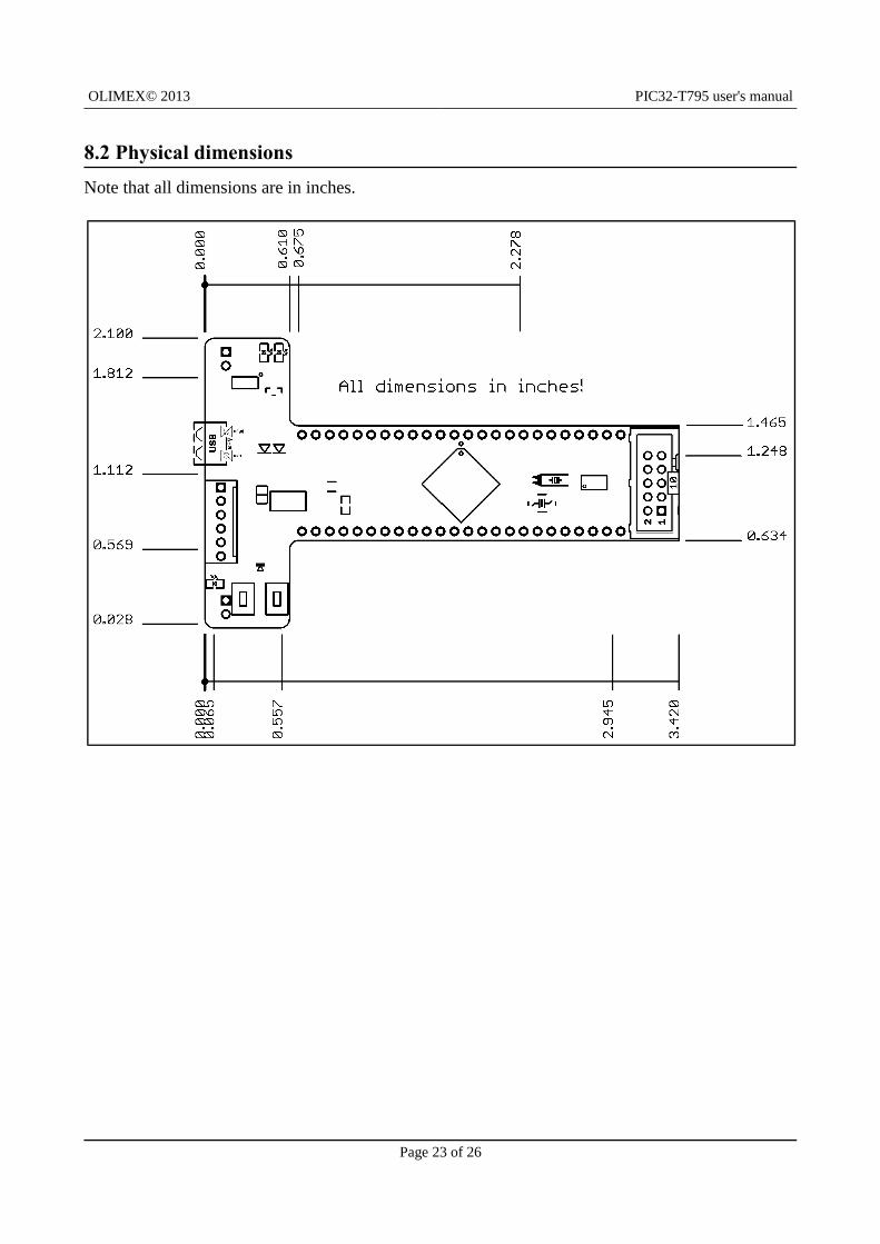
8.2 Physical dimensions
Note that all dimensions are in inches.
Page 23 of 26
OLIMEX© 2013 PIC32-T795 user's manual
CHAPTER 9 REVISION HISTORY
9. Introduction to the chapter
In this chapter you will find the current and the previous version of the document you are reading. Also the web-page for your device is listed. Be sure to check it after a purchase for the latest available updates and examples.
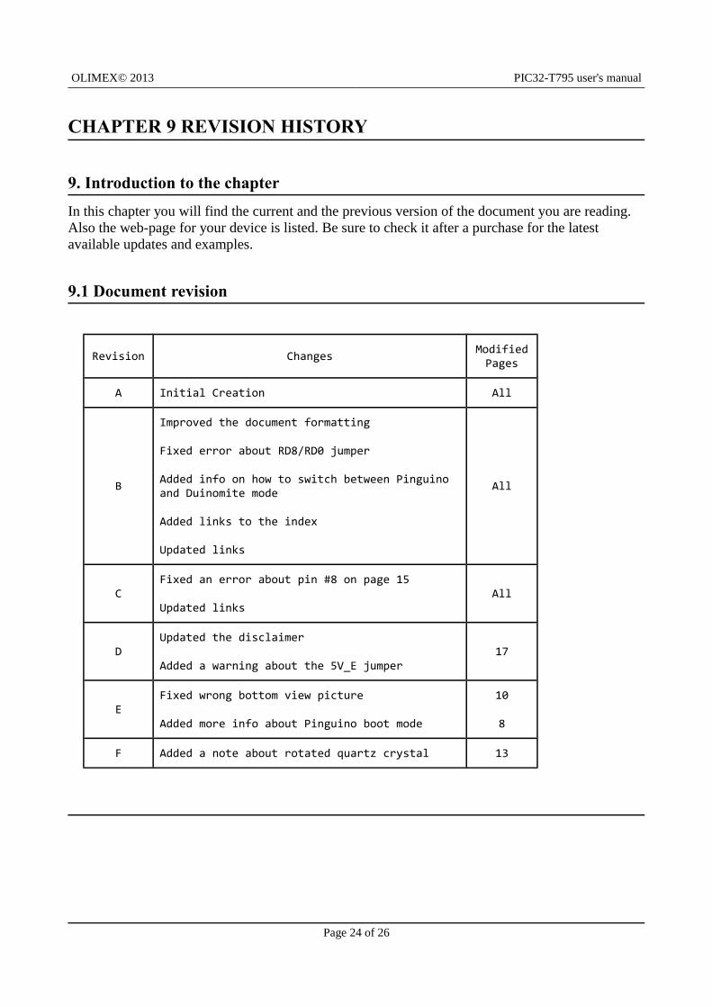
9.1 Document revision
Revision Changes ModifiedPages
A Initial Creation All
B
Improved the document formatting
Fixed error about RD8/RD0 jumper
Added info on how to switch between Pinguino and Duinomite mode
Added links to the index
Updated links
All
CFixed an error about pin #8 on page 15
Updated linksAll
DUpdated the disclaimer
Added a warning about the 5V_E jumper17
EFixed wrong bottom view picture
Added more info about Pinguino boot mode
10
8
F Added a note about rotated quartz crystal 13
Page 24 of 26
OLIMEX© 2013 PIC32-T795 user's manual
9.2 Web page of your device
The web page you can visit for more info on your device is https://www.olimex.com/Products/Duino/PIC32/PIC32-T795/. There you can find more info and some examples.
ORDER CODES:
PIC32-T795 – completely assembled and tested
USB-MINI-CABLE – USBmini to USB-A cable
PIC-KIT3 – for custom programming/debugging
How to order?
You can order directly using our web shop or via any of our distributors. The list of distributors is available here: https://www.olimex.com/Distributors/.
Check our webpage https://www.olimex.com/ for more info.
Page 25 of 26
OLIMEX© 2013 PIC32-T795 user's manual
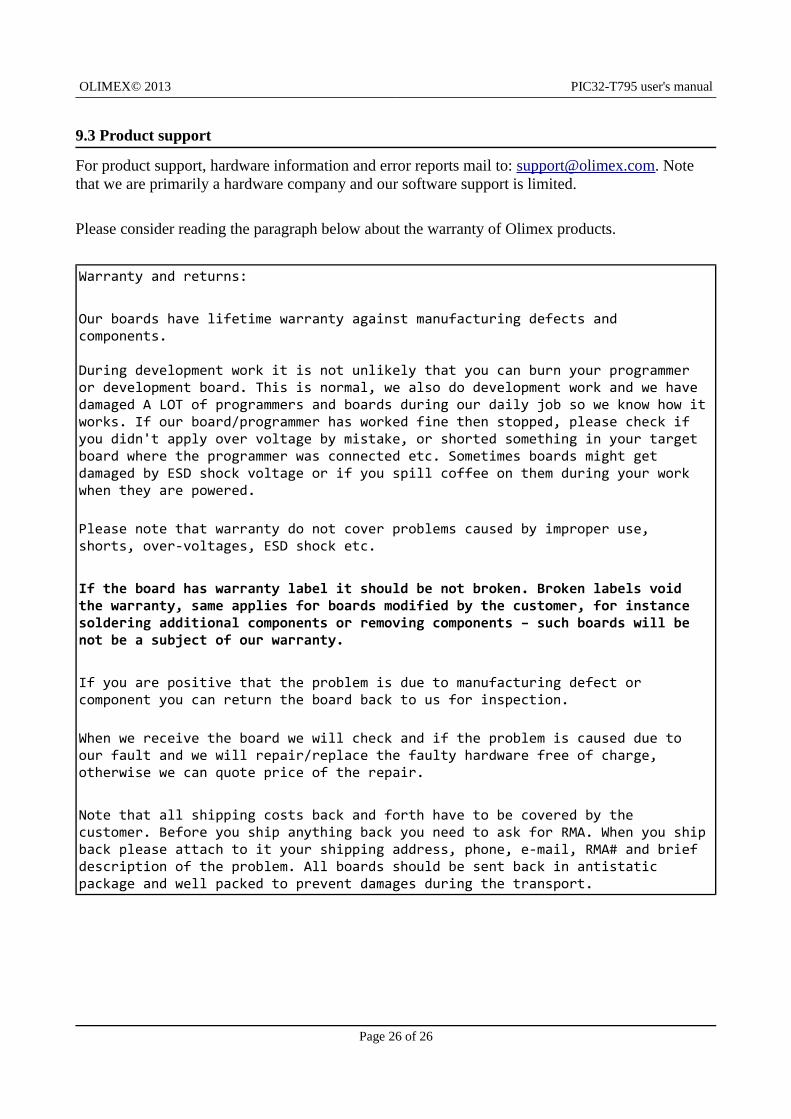
9.3 Product support
For product support, hardware information and error reports mail to: [email protected]. Note that we are primarily a hardware company and our software support is limited.
Please consider reading the paragraph below about the warranty of Olimex products.
Warranty and returns:
Our boards have lifetime warranty against manufacturing defects and components.
During development work it is not unlikely that you can burn your programmer or development board. This is normal, we also do development work and we have damaged A LOT of programmers and boards during our daily job so we know how itworks. If our board/programmer has worked fine then stopped, please check if you didn't apply over voltage by mistake, or shorted something in your target board where the programmer was connected etc. Sometimes boards might get damaged by ESD shock voltage or if you spill coffee on them during your work when they are powered.
Please note that warranty do not cover problems caused by improper use, shorts, over-voltages, ESD shock etc.
If the board has warranty label it should be not broken. Broken labels void the warranty, same applies for boards modified by the customer, for instance soldering additional components or removing components – such boards will be not be a subject of our warranty.
If you are positive that the problem is due to manufacturing defect or component you can return the board back to us for inspection.
When we receive the board we will check and if the problem is caused due to our fault and we will repair/replace the faulty hardware free of charge, otherwise we can quote price of the repair.
Note that all shipping costs back and forth have to be covered by the customer. Before you ship anything back you need to ask for RMA. When you shipback please attach to it your shipping address, phone, e-mail, RMA# and brief description of the problem. All boards should be sent back in antistatic package and well packed to prevent damages during the transport.
Page 26 of 26