Embed Size (px)
Citation preview

PICmicrotm Development Board
Crownhill Associates smart electronic solutions

PROTON Development Board MKII
Copyright Crownhill 2003 1
PROTON Board User Manual.
Release 2.0, 2003.
Disclaimer In order to comply with EMC directive 89/336/EEC, this product should not be used outside of a classroom or laboratory environment. Any software supplied with this product is provided in an “as is” condition. No warranties, whether express, implied or statutory, including, but not limited to, implied warranties of mer-chantability and fitness for a particular purpose apply to this software. The company shall not, in any circumstances, be liable for special, incidental or consequential damages, for any rea-son whatsoever. This product should not be used as a critical component in life support systems. Crownhill does not recommend the use of any of its products in life support applications where the failure or malfunction of the product can reasonably be expected to cause failure in the life support system or to significantly affect its safety or effectiveness. In producing this document and the associated hardware we have spent a great deal of time to ensure the accuracy of the information presented. We constantly strive to improve the quality of our products and documentation. Crownhill operates a quality system conforming to the requirements of BS EN ISO9001 : 2000. Crownhill reserves the right to change the func-tionality and specifications of its products from time to time without prior notice. If you should find any errors or omission in these documents or hardware, please contact us, we appreciate your assistance in improving our products and services. Crownhill reserves the right to make changes to the products contained in this publica-tion in order to improve design, performance or reliability. Crownhill assumes no responsibil-ity for the use of any circuits described herein, conveys no license under any patent or other right, and makes no representation that the circuits are free of patent infringement. Charts and schedules contained herein reflect representative operating parameters, and may vary depending upon a user’s specific application. While the information in this publication has been carefully checked, Crownhill shall not be liable for any damages arising as a result of any error or omission. PICmicrotm is a trade name of Microchip Technologies Inc. PROTONtm is a trade name of Crownhill Associates Ltd. EPICtm is a trade name of microEngineering Labs Inc. This document was published by Crownhill associates limited, Cambridge England, 2003

PROTON Development Board MKII
Copyright Crownhill 2003 2
PROTON Board User Manual.
Release 2.0, 2003.
Table of Contents. Disclaimer....................................................................................1 Introduction .................................................................................3 Adding the Graphic LCD. ...........................................................4 Graphic LCD test program. ........................................................5 Circuit Diagram. ..........................................................................7 Power Supply. .............................................................................7 In-Circuit-Programming Header.................................................8 RS232 Transceiver. .....................................................................9 Alphanumeric LCD....................................................................10 Graphic LCD. .............................................................................11 16-Button Keypad. ....................................................................12 8 x LEDs.....................................................................................13 100K Potentiometer. .................................................................14 PICmicrotm Microcontroller. .....................................................15 I2C Eeprom. ...............................................................................16 SPI Eeprom................................................................................17 Infra-red Transmitters and Receiver........................................18 40 pin Microcontroller link socket. ..........................................19 Solderless Breadboard area. ...................................................20 The PROTON Board and the PROTON Compilers .................21 On-Board Serial Bootloader.....................................................22 Using the built-in PIC16F87x bootloader ................................22

PROTON Development Board MKII
Copyright Crownhill 2003 3
PROTON Board User Manual.
Release 2.0, 2003.
Introduction The Crownhill PROTON PICmicrotm Development Board is a must for develop-ers of PICmicrotm applications. Whether just beginning, or a seasoned veteran, the PROTON board offers a rapid solution to be realised. On board peripherals include, 16-button keypad, LCD (graphic or alphanu-meric), LEDs (4x red, 4 x green), serial eeproms (I2C and SPI), RS232 serial port, Infra-red transmitters and receiver, and a choice of crystal frequencies. Not to mention the PICmicro's own facilities, such as 8K program space, 368 bytes of user RAM, 256 bytes of user eeprom, Eight channel Analogue to Digital converter, USART, MSSP module offering PWM, I2C, SPI, and parallel configu-rations. The choice of options is extensive enough to make the PROTON board a single solution for a multitude of challenges.
16-key KEYPADInfrared Sensor
Infrared Diodes
RS232 Serial Port
In CircuitProgramming Header
AC/DC 9 to 12 VoltsPower Socket
8 x LEDs
Alphanumeric LCDGraphic LCD
or Both
On-boardremoveablePIC16F877
microcontroller I2C eeprom
RESET button
SolderlessBreadboard
Development areawith
SMT pads
Potentiometer
PROTON Development Board MKII
Copyright Crownhill 2003 4
PROTON Board User Manual.
Release 2.0, 2003.
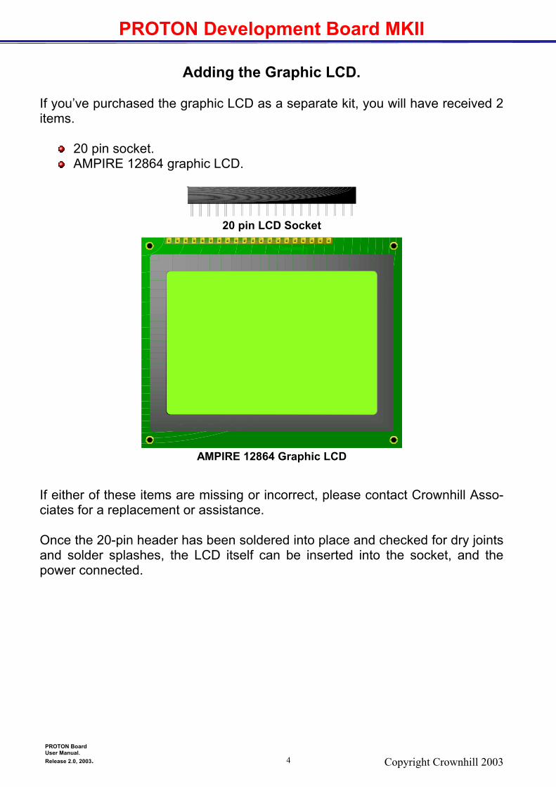
Adding the Graphic LCD. If you’ve purchased the graphic LCD as a separate kit, you will have received 2 items.
20 pin socket. AMPIRE 12864 graphic LCD.
If either of these items are missing or incorrect, please contact Crownhill Asso-ciates for a replacement or assistance. Once the 20-pin header has been soldered into place and checked for dry joints and solder splashes, the LCD itself can be inserted into the socket, and the power connected.
20 pin LCD Socket
AMPIRE 12864 Graphic LCD

PROTON Development Board MKII
Copyright Crownhill 2003 5
PROTON Board User Manual.
Release 2.0, 2003.
Graphic LCD test program. The graphic LCD itself will not do much of anything, until it has a program con-trolling it. So in order to test the graphic LCD, type in the program below. Note: this program, as with all the programs in this manual, is written for the Crownhill PROTON+ compiler Version 2.0. Ensure that a 4MHz crystal or resonator is fitted into the XTAL socket, as the program is written for this speed oscillator.
Program listing Removed from web download

PROTON Development Board MKII
Copyright Crownhill 2003 6
PROTON Board User Manual.
Release 2.0, 2003.
Infra-red test program. As with the graphic LCD, the infra-red components don't do a great deal until a program controls them, or takes control from them. So we'll test the infra-red receiver module, by creating a program to decode sig-nals sent by a Sony remote control handset. Type in the following program:
Program listing Removed from web download

PROTON Development Board MKII
Copyright Crownhill 2003 7
PROTON Board User Manual.
Release 2.0, 2003.
Circuit Diagram. The circuit of the PROTON development board is split into several sections, each attached to the on-board PICmicrotm microcontroller in some way.
Power Supply. In-Circuit-Programming. RS232 Transceiver. Graphic LCD (optional). Alphanumeric LCD. 16 button Keypad. 8 LEDs. 100kΩ Potentiometer. PIC16F877 PICmicro Microcontroller. SPI eeprom (optional). I2C eeprom. Infrared Transmitters / Receiver (optional). 40 Pin Microcontroller Link socket. Solderless breadboard.
Power Supply.
The power supply is a conventional rectifier – regulator type, supplying 5 Volts to the board with approx 500mA to 750mA of current. Using the bridge rectifier allows both an external AC or DC supply of between 6 and 9 Volts to be used. Any higher than 9 Volts will cause the 7805 regulator to become unreliably hot. The circuit of the Power supply is shown below: -
Schematic removed from web download
Power Supply circuit.

PROTON Development Board MKII
Copyright Crownhill 2003 8
PROTON Board User Manual.
Release 2.0, 2003.
In-Circuit-Programming Header. The In-Circuit-Programming section, allows the on-board 16F877 PICmicrotm, to be programmed in circuit. A suitable programmer must be used, such as the microEngineering Labs EPICtm programmer. The circuit for this section is shown below: - The PICmicrotm programmer must be fitted to the 10-pin header, preferably us-ing a short ribbon cable and suitable header sockets. The programming pins are connected to the relevant programming pins of the PICmicro. The inclusion of the push switch allows the PICmicrotm to be RESET while developing software. D9 stops any high voltage leaking into the 5 Volt supply when the microcontrol-ler is being programmed, as most devices require at least 12 Volts on their VPP pins. Resistor R9 stops the 5 Volt line from becoming short circuit when the RESET switch is operated.
Schematic removed from web download
In-Circuit-Programming section.

PROTON Development Board MKII
Copyright Crownhill 2003 9
PROTON Board User Manual.
Release 2.0, 2003.
RS232 Transceiver. The RS232 Transceiver section, uses the ever popular MAX232 device from MAXIM semiconductors. Serial communication is a useful aid to debugging mi-crocontroller code. The MAX232 ensures that the correct voltage levels are seen by both the computer and the microcontroller, as well as serving to isolate the two devices somewhat. This section is shown below: -
Schematic removed from web download
RS232 Transceiver circuit. The input and output pins of the MAX232 are connected to pins RC6 and RC7 of the PICmicrotm. This allows the implementation of the hardware USART for serial IO, as well as a bit-bashed method. A simple test of the serial port is shown below: - INCLUDE "PROTON_4.INC" ' Use a 4MHz XTAL RSOUT "HELLO WORLD" ' Send some text Loop: PRINT RSIN ' Display typed characters GOTO Loop The above program outputs the string "HELLO WORLD" serially. This may be monitored using HyperTerminal or the compiler’s build in serial terminal pro-gram. It then sits in a loop, displaying on the LCD, characters typed on the computer.

PROTON Development Board MKII
Copyright Crownhill 2003 10
PROTON Board User Manual.
Release 2.0, 2003.
Two types of LCD are supported with the PROTON board, an alphanumeric type based on the Hitachi HD44780 chipset. And a Graphics type based on the Samsung KS0108 chipset. The PROTON board comes supplied with the alphanumeric type as standard. However, the graphics LCD may be purchased separately from Crownhill Asso-ciates. Each LCD has a relevant socket associated with it. The graphic LCD's socket is supplied when the LCD is purchased from Crownhill (See the relevant section in this manual for details). The smaller of the two sockets is for the alphanumeric LCD.
Alphanumeric LCD. Shown below is the circuit for the Alphanumeric LCD, and it's connections to the PICmicrotm.
Schematic removed from web download
Alphanumeric LCD circuit. A simple test program is shown below:- INCLUDE "PROTON_4.INC" ' Use a 4MHz XTAL CLS PRINT "HELLO WORLD" ' Display some text STOP

PROTON Development Board MKII
Copyright Crownhill 2003 11
PROTON Board User Manual.
Release 2.0, 2003.
Graphic LCD. The graphic LCD's circuit and connections to the PICmicrotm is shown below:-
Schematic removed from web download
Graphic LCD circuit. The graphic LCD supported by the PROTON board is a 64 x 128 pixel type, us-ing the Samsung KS0108 chipset. The jumper J6, enables/disables the LCD's backlight. Note that a graphic LCD with backlight facility must be used in con-junction with jumper J6. A small program demonstrating the LCD is shown below: INCLUDE "PROTON_G4.INT" ' Use a 4MHz XTAL CLS PRINT "HELLO WORLD" ' Display some text STOP INCLUDE "FONT.INC" ' Add the LCD's Font

PROTON Development Board MKII
Copyright Crownhill 2003 12
PROTON Board User Manual.
Release 2.0, 2003.
16-Button Keypad. The PROTON board has 16-buttons arranged in a keypad matrix, connected to PORTB of the PICmicrotm. Resistors R1, R2, R4,and R5, offer a measure of protection in the event that a short may appear on the PIC's IO lines. R3 acts as a pull down resistor for switches S13, S14,S15, and S16. These may then be used as standard push switches. The circuit for the keypad matrix is shown be-low: -
16-Button Keypad circuit. A small program demonstrating the keypad is shown below: - INCLUDE "PROTON_4.INC" ' Use a 4MHz XTAL CLS Loop: PRINT AT 1 , 1 , DEC INKEY , " " ' Display the key press GOTO Loop
S1R2470
S5
S9
S13 S14
S10
S6
S2 S3
S7
S11
S15 S16
S12
S8
S4
R1470
R5470
R4470
R347K
RB3
RB2
RB1
RB0
RB4
RB5
RB6
RB7
PROTON Development Board MKII
Copyright Crownhill 2003 13
PROTON Board User Manual.
Release 2.0, 2003.
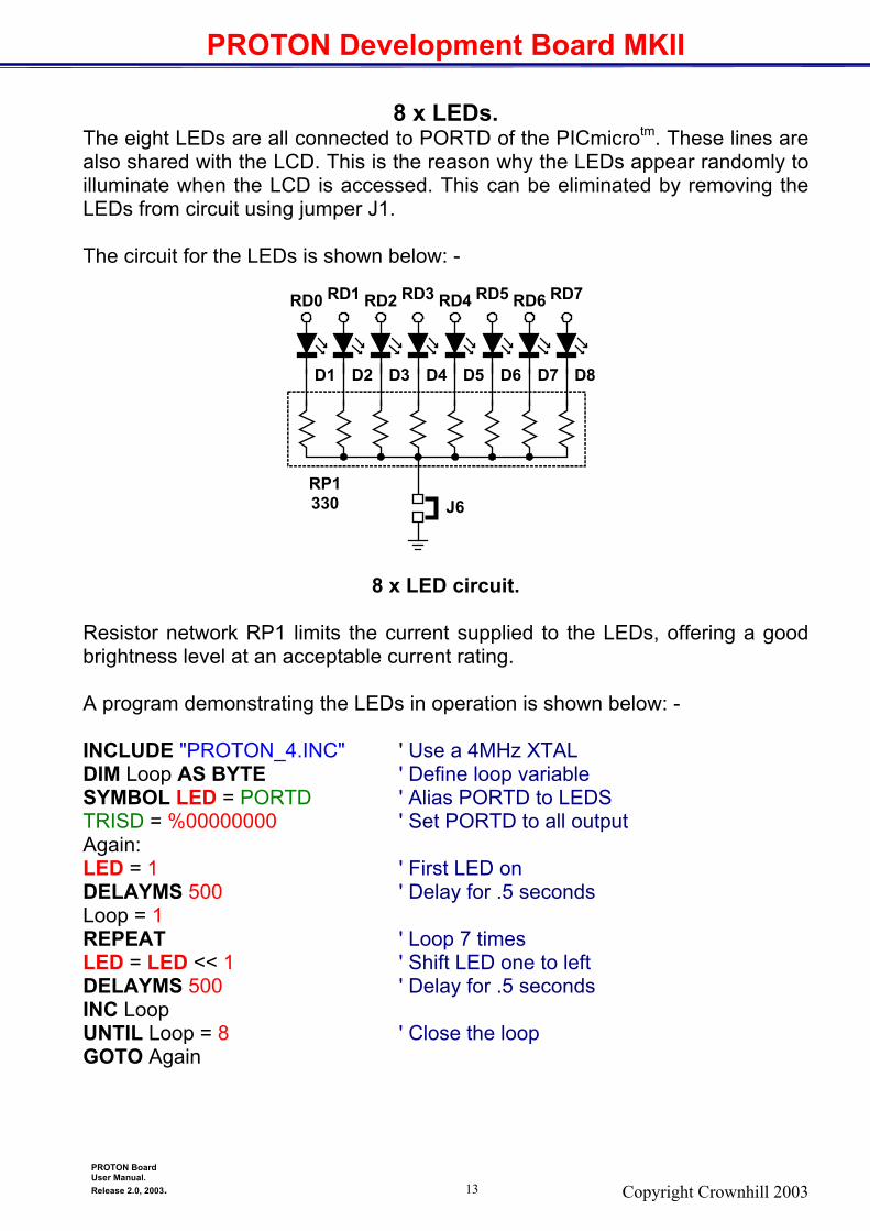
8 x LEDs. The eight LEDs are all connected to PORTD of the PICmicrotm. These lines are also shared with the LCD. This is the reason why the LEDs appear randomly to illuminate when the LCD is accessed. This can be eliminated by removing the LEDs from circuit using jumper J1. The circuit for the LEDs is shown below: -
8 x LED circuit. Resistor network RP1 limits the current supplied to the LEDs, offering a good brightness level at an acceptable current rating. A program demonstrating the LEDs in operation is shown below: - INCLUDE "PROTON_4.INC" ' Use a 4MHz XTAL DIM Loop AS BYTE ' Define loop variable SYMBOL LED = PORTD ' Alias PORTD to LEDS TRISD = %00000000 ' Set PORTD to all output Again: LED = 1 ' First LED on DELAYMS 500 ' Delay for .5 seconds Loop = 1 REPEAT ' Loop 7 times LED = LED << 1 ' Shift LED one to left DELAYMS 500 ' Delay for .5 seconds INC Loop UNTIL Loop = 8 ' Close the loop GOTO Again
RP1330
D1 D2 D3 D4 D5 D6 D7 D8
RD0 RD1 RD2 RD3 RD4 RD5 RD6 RD7
J6

PROTON Development Board MKII
Copyright Crownhill 2003 14
PROTON Board User Manual.
Release 2.0, 2003.
100K Potentiometer. In order to use the PICmicro’s ADC, potentiometer VR3 is added to the PRO-TON board. This is connected to bit 0 of PORTA (AN0), and may be discon-nected from circuit by the use of J10. The circuit for the potentiometer is shown below: -
Potentiometer circuit. A program demonstrating the potentiometer in operation is shown below: - ' Program to measure voltage (0-5VDC) and display on LCD ' This program uses the */ operator to scale the ADC result from 0-1023 ' to 0-500. Then */ performs a divide by 256 automatically, allowing math which ' would normally exceed the limit of a WORD variable. Include "PROTON_4.INC" ' Define ADC parameters ADIN_RES = 10 ' 10-bit result required ADIN_TAD = FRC ' RC OSC chosen ADIN_STIME = 50 ' Allow 50us sample time DIM ADVAL AS WORD ' Create ADVAL to store result TRISA = %11111111 ' Set PORTA to all input ADCON1 = %10000010 ' Set PORTA analogue and right justify result DELAYMS 500 ' Wait .5 second CLS ' Clear LCD Loop: ADVAL = ADIN 0 ' Read channel 0 to ADVAL (0-1023) ADVAL = (ADVAL */ 500) >> 2 ' Display the decimal value PRINT AT 1,1,"DC Volts= ",DEC (ADVAL / 100),".", DEC2 ADVAL," " DELAYMS 100 ' Wait .1 second GOTO Loop ' Do it forever
5 Volts
0V
VR3100kRA0
J7

PROTON Development Board MKII
Copyright Crownhill 2003 15
PROTON Board User Manual.
Release 2.0, 2003.
PICmicrotm Microcontroller. The PROTON board has at the heart of it a PIC16F877 microcontroller. This device offers 8k (8192 bytes) of program space, and 368 bytes of user RAM, as well as built in peripherals such as USART, ADC, SPI, I2C, and many more. Each section of the PROTON board is attached in some way to this device. The circuit below illustrates the connections to the various sections.
Schematic removed from web download
PICmicrotm Microcontroller circuit. Different frequency crystals or resonators are catered for by inserting the ap-propriate quartz component in the XTAL Socket. The board also caters for the 3 pin type resonators.

PROTON Development Board MKII
Copyright Crownhill 2003 16
PROTON Board User Manual.
Release 2.0, 2003.
I2C Eeprom. The PROTON board caters for two types of serial eeprom. An SPI type, and an I2C type. The I2C eeprom (type 24LC128) is supplied with the board. This eeprom has a capacity of 128k-bits, which in byte terms is 16k bytes. The circuit below shows the connections of the I2C eeprom to the PICmicrotm.
Schematic removed from web download
I2C eeprom circuit. Because the I2C architecture relies on open-collector IO lines, resistors R7, and R8 are in circuit. However, because other devices may need to be attached to pins RC3, and RC4 of the PICmicrotm, these resistors need to be removable. Therefore, jumpers J7, and J8, isolate the relevant resistor. When the I2C eeprom is required these jumpers must be in place. The program below dem-onstrates writing and reading to the I2C eeprom. INCLUDE "PROTON_4.INC" ' Use a 4MHz XTAL CLS BUSOUT $A0 , 1000 , [123] ' Write to address 1000 DELAYMS 10 ' Wait for write to happen PRINT DEC3 BUSIN $A1 , 1000 ' Read back the address STOP

PROTON Development Board MKII
Copyright Crownhill 2003 17
PROTON Board User Manual.
Release 2.0, 2003.
SPI Eeprom. SPI eeproms use a different architecture to I2C types, therefore they do not re-quire resistors R7,or R8. SPI eeproms are usually denoted by the component name 25XXX, where XXX is the memory capacity of the eeprom. A popular SPI eeprom is the 25LC640. This has a capacity of 64k bits, which amounts to 8192k bytes. Shown below is the circuit for the SPI eeprom section of the PROTON board, and it's connections to the PICmicrotm: -
Schematic removed from web download
SPI eeprom circuit. A simple demonstration program for accessing the SPI eeprom is shown below. INCLUDE "PROTON_4.INC" ' Use a 4MHz XTAL DIM ADR AS WORD DIM BYTEIN AS BYTE CLS ADR = 1000 ' Eeprom address 1000 LOW CS ' Enable the eeprom SHOUT SI,SCK,MSBFIRST,[6] ' Send WRITE ENABLE TOGGLE CS ' Execute the command ' Send address and data value 123 SHOUT SI,SCK,MSBFIRST,[2,ADR.byte1,ADR.byte0,123] HIGH CS ' Disable the eeprom DELAYMS 5 ' Allow the eeprom to allocate the byte LOW CS ' Enable the eeprom ' Send READ COMMAND and address SHOUT SI,SCK, MSBFIRST,[3,ADR.byte1,ADR.byte0] SHIN SO,SCK,MSBPRE,[ BYTEIN] ' Read data HIGH CS ' Disable the eeprom PRINT DEC BYTEIN STOP

PROTON Development Board MKII
Copyright Crownhill 2003 18
PROTON Board User Manual.
Release 2.0, 2003.
Infra-red Transmitters and Receiver. The PROTON board incorporates an infra-red receiver module, and also two in-fra-red LEDs. Transistors, Q1 and Q2 act as buffers for the infrared LEDs. Jumpers J4, and J5 isolate the LEDs from the PICmicrotm IO pins. J3 isolates the receiver mod-ule.
Schematic removed from web download
Infra-Red Transmitters / Receiver circuit.

PROTON Development Board MKII
Copyright Crownhill 2003 19
PROTON Board User Manual.
Release 2.0, 2003.
40 pin Microcontroller link socket. In order for the solderless breadboard to connect to the PICmicrotm at the heart of the PROTON board, each of its pins is brought out to a line on a 40 pin socket, J1. The connections to the 40 pin socket are illustrated below. Connecting the breadboard to the 40 pin socket, is a simple matter of wiring. Shown below is a connection to RA0 of the PICmicrotm, using one of the pre-cut and formed wires in the Wire Jumper kit available from Crownhill.
RB
6
RB
4
RB
2
RB
0+
5V
RD
6
RD
4
RC
6
RC
4
RD
2R
D0
RC
2
RC
0O
SC
2
0V
RE
1
RA
5
RA
3
RA
1
VP
PR
B7
RB
5
RB
3
RB
1
0VR
D7
RD
5
RC
7
RC
5
RD
3R
D1
RC
3
RC
1
OS
C1
+5V
RE
2
RE
0
RA
4
RA
2
RA
0
RB
6
RB
4
RB
2
RB
0+
5V
RD
6
RD
4
RC
6
RC
4
RD
2
0V
RB
7
RB
5
RB
3
RB
1
RD
7
RD
5
RC
7
RC
5
RD
3
1 2 3 4 5 6 7 8 9 10 11 12 13 14 15 16 17 18 19 20 21 22 23 24 26 27 28 29 3025
1 2 3 4 5 6 7 8 9 10 11 12 13 14 15 16 17 18 19 20 21 22 23 24 26 27 28 29 3025
ab
cd
ef
gh
ij
kl
ab
cd
ef
gh
ij
kl
RD
0
RC
2
RC
0O
SC
2
RE
1
RA
5
RA
3
RA
1
VP
P
0V
RD
1
RC
3
RC
1
OS
C1
+5V
RE
2
RE
0
RA
4
RA
2
RA
0

PROTON Development Board MKII
Copyright Crownhill 2003 20
PROTON Board User Manual.
Release 2.0, 2003.
Solderless Breadboard area. The solderless breadboard area of the PROTON board, makes rapid prototyp-ing possible, as well as re-use of valuable components. The breadboard is laid out in a standard configuration, however, if you’re not familiar with solderless breadboards, the diagram below shows the board as if an X-ray had been taken. You can clearly see the internal connections.
Transparent view of solderless breadboard. The bottom strip (with a black line below it) is already connected to 0 Volts, and the strip above it (with a red line above it) is connected to +5 Volts. As shown below.
1 2 3 4 5 6 7 8 9 10 11 12 13 14 15 16 17 18 19 20 21 22 23 24 26 27 28 29 3025
1 2 3 4 5 6 7 8 9 10 11 12 13 14 15 16 17 18 19 20 21 22 23 24 26 27 28 29 3025
ab
cd
ef
gh
ij
kl
ab
cd
ef
gh
ij
kl
+5 Volts
0 Volts
Not Connected

PROTON Development Board MKII
Copyright Crownhill 2003 21
PROTON Board User Manual.
Release 2.0, 2003.
The PROTON Board and the PROTON Compilers The PROTON board was designed primarily with the PROTON compilers in mind. However, this does not bar it from being used with any PICmicrotm lan-guage, either high-level, or assembler. But for this section, as in the rest of the manual, we’ll stick with the PROTON+ compiler. The CDROM supplied with the PROTON board, has a LITE version of the PROTON+ compiler. The LITE version is fully functional, but is restricted to 35 lines of code, and only one command per line, as opposed to unlimited lines and multiple commands per line in the full version. This allows a fair appraisal of it’s merits, and strengths. Within the LITE version’s folder, you will find example software for use with the PROTON board, ranging from simple LED flashing to a demonstration of the hardware USART. Most of the examples do not require any additional components for them to work, relying on the PROTON board’s wealth of on-board peripherals. However, there is one program in particular that requires an extra component to be wired up on the solderless breadboard. This is OWRITE.BAS. The OWRITE.BAS program, demonstrates measuring the temperature using a Dallas Semiconductors (now MAXIM), DS1820. This requires the inclusion of two components, a DS1820, and a 4.7KΩ resistor. The diagram below shows a possible layout for the circuit.
RB
6
RB
4
RB
2
RB
0+
5V
RD
6
RD
4
RC
6
RC
4
RD
2
0V
RB
7
RB
5
RB
3
RB
1
RD
7
RD
5
RC
7
RC
5
RD
3
1 2 3 4 5 6 7 8 9 10 11 12 13 14 15 16 17 18 19 20 21 22 23 24 26 27 28 29 3025
1 2 3 4 5 6 7 8 9 10 11 12 13 14 15 16 17 18 19 20 21 22 23 24 26 27 28 29 3025
ab
cd
ef
gh
ij
kl
ab
cd
ef
gh
ij
kl
RD
0
RC
2
RC
0O
SC
2
RE
1
RA
5
RA
3
RA
1
VP
P
0V
RD
1
RC
3
RC
1
OS
C1
+5V
RE
2
RE
0
RA
4
RA
2
RA
0
DS1820

PROTON Development Board MKII
Copyright Crownhill 2003 22
PROTON Board User Manual.
Release 2.0, 2003.
On-Board Serial Bootloader. The 16F877 PICmicrotm supplied with the PROTON board, has a serial boot-loader pre-programmed into it. What this means is that the device can be pro-grammed using nothing more than the serial port of the PC. We’ll take the OW-RITE program as an example of this. Ensure that the PROTON board is connected to the PC using a suitable 9-pin serial cable, and is being supplied with it’s correct voltage (6 – 9 Volts). Now load and compile the OWRITE.BAS program.
Using the built-in PIC16F87x bootloader A boot loader allows the PICmicro to be programmed using a simple serial ca-ble from the computer's COM port. Before the bootloader may be used, the target PICmicro must be programmed conventionally with one of the bootloader hex files. This is the code that resides in the PIC and intercepts the serial data presented from the PC. The HEX files may be found in the LOADER_HEX folder. Each type of 16F87x PICmicro and crystal combination requires a different hex file, for example, a 16F877 device working with a 20MHz crystal requires the PIC16F877_20.HEX file pro-grammed. There is however, one other requirement, because the configuration fuses are not alterable by the bootloader, you must decide whether to have the watchdog timer enabled or disabled in the target PICmicro. There are two main folders in the LOADER_HEX folder, these are WDT_ON, and WDT_OFF. The WDT_ON folder contains the boot hex files with the watchdog timer enabled, and the WDT_OFF folder contains hex files with the watchdog timer disabled. Remember, the default of the compiler when using a conventional programming method is watchdog timer enabled. The bootloader is chosen by clicking on the appropriate iconic button, located at the top of the editor. See below: -
You may choose one of the available serial port on the PC for the attachment of the bootloader, by selecting COM1, COM2, or COM3 in the drop down menu. The default port is COM1. The port, as well as other parameters will be remem-bered, so there is no need to continually alter the settings.
Compile
Program
Download
View

PROTON Development Board MKII
Copyright Crownhill 2003 23
PROTON Board User Manual.
Release 2.0, 2003.
Other aspects of the downloader may also be altered by clicking the CONFIG menu (shown below).
The DTR CONTROL option has four settings: - HIGH. Will set the DTR line high while writing is in progress. LOW. Will pull the DTR line low while writing is in progress. STROBE HIGH. Will toggle the DTR line LOW-HIGH-LOW while writing is in progress. STROBE LOW. Will toggle the DTR line HIGH-LOW-HIGH while writing is in progress. The RTS CONTROL option also has four settings: - HIGH. Will set the RTS line high while writing is in progress, and keep it high af-terwards LOW. Will pull the RTS line low while writing is in progress. STROBE HIGH. Will toggle the RTS line LOW-HIGH-LOW while writing is in progress. STROBE LOW. Will toggle the RTS line HIGH-LOW-HIGH while writing is in progress. PROGRAM EEPROM. Will program the on-board eeprom along with the main program code, if checked. CLOSE ON COMPLETION. Will automatically close the bootloader window if a successful write is carried out. In normal operation, the bootloader will automatically search for the bootloader receiver software in the PICmicro, however, for this to be found, the PICmicro must be RESET or powered up.

PROTON Development Board MKII
Copyright Crownhill 2003 24
PROTON Board User Manual.
Release 2.0, 2003.
You will then be prompted with the message shown below. Clicking on the WRITE button will also start the download process.
Once the RESET button on the PROTON board is activated, the program will download and run automatically. That's all there is to it. What is a bootloader? The PIC16F87x, and all the 16-bit core range of devices have a unique feature, they can program their own FLASH code space while running. All other PICmicro's must be programmed by a device programmer, such as the PIC-STARTtm or EPICtm programmers. This self-modifying feature allows a PIC16F87x device to run a program named a bootloader. A bootloader is a program that resides in the code space of the target PICmicro. It can be activated to allow additional program code to be written to and read from that same target PICmicro. A bootloader consists of 2 elements, con-nected by a serial cable. The first part of the bootloader is a program resident on the PICmicro. This pro-gram occupies the upper 256 words of the FLASH code space. This small pro-gram must be placed into the PICmicro using a conventional programmer. The program resident in the PICmicro communicates with the second element of the loader over a serial connection. This second program is the bootloader window within the compiler's IDE and is the user interface. It allows the com-piled BASIC code to be programmed. Only the code space and data space may be read and programmed on the tar-get PICmicro. The ID space and CONFIGURATION fuses are not accessible to the bootloader. The configuration fuses must be set at the time the actual loader program is programmed into the PICmicro. Once they are set, they cannot be changed by the bootloader. The bootloader software resident in the PICmicro, intercepts the reset vector. When the PICmicro powers up, it enters the loader's boot supervisor, this watches the USART's serial input pin for a start bit for 200 milliseconds (ms). If it sees activity during this period, it enters the communications section of the

PROTON Development Board MKII
Copyright Crownhill 2003 25
PROTON Board User Manual.
Release 2.0, 2003.
software to download a program. If it does not see any activity during the 200ms, it starts the user program in the PICmicro. The interception of the reset vector is accomplished by automatically relocating the first 4 user program words from address's 0 to 3 to a reserved place in the bootloader's code space (within the top 256 words). A jump to the bootloader is then placed at locations 0 to 3. When the loader software running on the PC reads or writes these addresses the values seen are as if the bootloader was not resident and the reset code had not been moved. The USART's serial pins used by the bootloader are only required when the loader is actually programming the PICmicro. They are unattached while the downloaded user program is running on the target and may be assigned to any other task or serial baud rate, with one exception. As we've already discussed, the bootloader checks the serial input pin at power up and reset, to determine if it should run, or if the user (downloaded) program should run. Therefore, for the user program to run, this pin must not be in the start bit condition when the de-vice is powered up. Make sure the serial in pin (PORTC.7) is in the idle state when the PIC is first powered up. The serial communication speed is set at 19200 baud. The bootloader program resident in the PICmicro can easily communicate at this speed with an oscillator frequency from 4MHz to 20MHz. This oscillator frequency is determined at the time the loader code is programmed into the target PICmicro. The target PICmicro must then only be run at this frequency in order to be able to commu-nicate with its matching part running on the PC. The bootloader uses no PICmicro resources while the user program is running. All the data memory, RAM, and I/O pins are available to the user program. However, there are a few considerations that should be noted when writing pro-grams that will be loaded by the bootloader. The first is that the bootloader takes over at power up and any subsequent resets. Any time the program vec-tors through the reset address, the loader becomes active and watches the RX pin (PORTC.7) for any activity. If there is any action on this pin, the loader will start, and the user program will not execute. Even if there is no activity on this pin, the start of the user program will be delayed by the 200 milliseconds while the bootloader is watching the RX pin. Another consideration is the fact that the configuration fuses are not alterable by the bootloader. If some programs require the use of the Watchdog Timer and others don't, then separate PICmicro's will be necessary. One PICmicro pro-grammed with the WDT on and one with it off. The same is true for the Power up Timer, Brownout Detect Enable and Oscillator type.

PROTON Development Board MKII
Copyright Crownhill 2003 26
PROTON Board User Manual.
Release 2.0, 2003.
The standard programmed defaults are WATCHDOG TIMER OFF, POWERUP TIMER ON, BROWNOUT DETECT ENABLE ON and HS OSCILLATOR. The configuration fuses for code protection CANNOT be enabled. The boot-loader needs to be able to freely read and write to the PICmicro's code and data space. Therefore, the device cannot be code protected. The bootloader is pri-marily aimed at development work, any final products that require code protec-tion must be programmed in the conventional way. The bootloader software occupies the last 256 words of code space. A compiled program is written starting at location 0 and grows upward so the loader's posi-tion in memory is not noticeable. You must make sure that the program code does not attempt to enter the upper 256 words of code space. The bootloader inserts its own code at the reset vector and automatically relocates the user's reset code to an area reserved within the top 256 words of memory. Normally, these locations contain a jump to the start-up routine for the user program. However, since the user code is no longer situated at these locations, the user program should not attempt to jump to, or call any routine within the code area between 0 and 3.