Embed Size (px)
Citation preview

picorio_doc DocumentationRelease 0.0.1
fuzexin
Mar 28, 2021


CONTENTS:
1 General Documentation 11.1 Introduction . . . . . . . . . . . . . . . . . . . . . . . . . . . . . . . . . . . . . . . . . . . . . . . 11.2 Project Roadmap . . . . . . . . . . . . . . . . . . . . . . . . . . . . . . . . . . . . . . . . . . . . . 21.3 FAQ . . . . . . . . . . . . . . . . . . . . . . . . . . . . . . . . . . . . . . . . . . . . . . . . . . . . 2
2 Hardware Projects 32.1 Pygmy_ES1Y Board . . . . . . . . . . . . . . . . . . . . . . . . . . . . . . . . . . . . . . . . . . . 32.2 RRV64 . . . . . . . . . . . . . . . . . . . . . . . . . . . . . . . . . . . . . . . . . . . . . . . . . . 52.3 Cache . . . . . . . . . . . . . . . . . . . . . . . . . . . . . . . . . . . . . . . . . . . . . . . . . . . 172.4 Contributing . . . . . . . . . . . . . . . . . . . . . . . . . . . . . . . . . . . . . . . . . . . . . . . 22
3 Software Projects 253.1 Firmware . . . . . . . . . . . . . . . . . . . . . . . . . . . . . . . . . . . . . . . . . . . . . . . . . 253.2 V8-RISCV . . . . . . . . . . . . . . . . . . . . . . . . . . . . . . . . . . . . . . . . . . . . . . . . 35
i

ii
CHAPTER
ONE
GENERAL DOCUMENTATION
1.1 Introduction
1.1.1 What is PicoRio
PicoRio is an open-source project stewarded by the RISC-V International Open Source (RIOS) laboratory, a nonprofitresearch lab at Tsinghua-Berkeley Shenzhen Institute (TBSI). The RIOS Lab focuses on elevating the RISC-V softwareand hardware ecosystem collaboratively with both academia and industry. In PicoRio, we create an open, affordable,Linux-capable RISC-V hardware platform to help software developers port modern applications that require Javascriptor GPUs. PicoRio will build upon high-quality IPs and software components contributed by experts from industry andacademia. PicoRio is not proprietary to any specific vendor or platform, and will have complete documentation thatcan help users build high-quality products in a short amount of time.
1.1.2 Motivation
A system is more than processors
• Large cost to license other IPs in SoC: cache, interconnects, graphics, camera ISP, etc
• An attractive open-source platform to experiment new hardware ideas
• Full-system support is indispensable to security and trusted executions.
• RISC-V hardware extensions: JIT runtime, vectorization, etc
The community lacks affordable RISC-V hardware platforms that is capable of executing diverse softwares
• Few low-cost, software-capable boards for the long tail of developers
• Developers won’t spend $1000 for a new hardware just for software development
1.1.3 Highlights
• Independently Maintained: The RIOS Lab is an independent nonprofit organization that governs the archi-tecture development, ensures compliance, and will publish the design. The RIOS Lab will be the gatekeeperfor both hardware and software, from SoC and firmware/drivers to high-level software and documentation. Pi-coRio will be vendor agnostic and non-proprietary. The RIOS Lab will work with academic and commercialorganizations that will commit to its expansion and volume manufacturing.
• Open Source: PicoRio will open source as many components as possible, including the CPU and main SoCdesign, chip package, board design files, device drivers, and firmware. The exceptions are foundry related IPs(e.g., TSMC SRAM configurations), commercial high-speed interfaces, and complex commercial IP blocks
1

picorio_doc Documentation, Release 0.0.1
like GPU. Nevertheless, our goal is to reduce the commercial closed source IPs for each successive release ofPicoRio, with the long term goal of having a version that is as open as possible.
• High-Quality IPs: A major goal of the RIOS lab is developing open source, hardware IPs with industrial qualityto boost the growth of RISC-V ecosystem and compete with those of existing, proprietary ISAs. Thus, PicoRioaims at a high-quality silicon release using open-source IPs. Such IPs will have gone through rigorous tapeoutverifications that meet industry quality. The openness of PicoRio will not come at the cost of lower quality IPblocks. In addition, we will open source our verification process, which can further enhance transparency andtrustworthiness.
• Modern Software Stack Support: PicoRio utilizes a heterogeneous multicore architecture and it isLinux-capable (RV64GC). We also designed PicoRio hardware to run modern managed languages such asJavaScript/WebAssembly as well as graphical applications like the Chrome web browser. In the RIOS Lab,PicoRio is also the hardware platform for several other open-source software projects, such as the RISC-V portsfor the V8 Javascript engine and the Chromium OS.
• Low-Power and Low-Cost: The target metrics of PicoRio are low power dissipation and cost, which is a perfectmatch to the target of RISC-V system design.
1.2 Project Roadmap
1.2.1 Three Phases of the PicoRio Development
We aim to incrementally improve PicoRio with each new release. We divide the development of PicoRio into threephases:
• First Phase (PicoRio 1.0): We include a basic 64-bit quad-core cache-coherent design (RV64GC) that runsfull Linux. We have already booted a Chromium OS kernel in command line mode. A standalone version ofChrome V8 Javascript engine will run directly on the kernel. We expect an early beta release late this year. This“headless” version of PicoRio should be fine for software development.
• Second Phase (PicoRio 2.0): In addition to the hardware improvement of the PicoRio v1.0, we are working withImagination™ to include a complete display pipeline (including a GPU) with video encode/decode capabilitiesto run graphics intensive applications like web browsers.
• Third Phase (PicoRio 3.0): Building upon the v2.0 hardware, we plan to further improve the CPU performanceto bring PicoRio to the level of a pad computer or laptop.
1.3 FAQ
1.3.1 How is PicoRio compared to Raspberry Pi?
Inspired by the Raspberry Pi, we propose the PicoRio project, whose goal is to produce RISC-V based small-boardcomputers at an affordable price point. PicoRio has differences in the following aspects:
• Open Source: Unlike Raspberry Pi, which uses proprietary Broadcom SoCs, PicoRio will open source as manycomponents as possible, including the CPU and main SoC design, chip package and board design files, devicedrivers, and firmware. Nevertheless, our goal is to reduce the commercial closed source IPs for each successiverelease of PicoRio, with the long term goal of having a version that is as open as practical.
• Low-Power and Low-Cost: The target metrics of PicoRio are long battery life and low cost, which is a bettermatch to RISC-V today, instead of high performance and large memory. In contrast, Raspberry Pi uses morepower hungry ARM processors. For example, the idle power consumption has risen from 0.4 Watts to 2.7 Wattsin the latest version of Raspberry Pi.
2 Chapter 1. General Documentation

CHAPTER
TWO
HARDWARE PROJECTS
This section describes the specification of PicoRio hardware components. We have grouped all the components into 4general classes according to their respective functionalities. The development status is also listed.
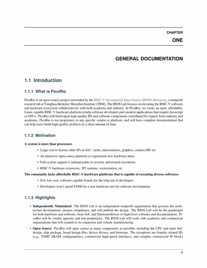
2.1 Pygmy_ES1Y Board
2.1.1 Pygmy_ES1Y chip Introduction
3
picorio_doc Documentation, Release 0.0.1
2.1.2 Pygmy_ES1Y EVB Hardware
Pygmy_ES1Y EVB Hardware configuration
4 Chapter 2. Hardware Projects
picorio_doc Documentation, Release 0.0.1
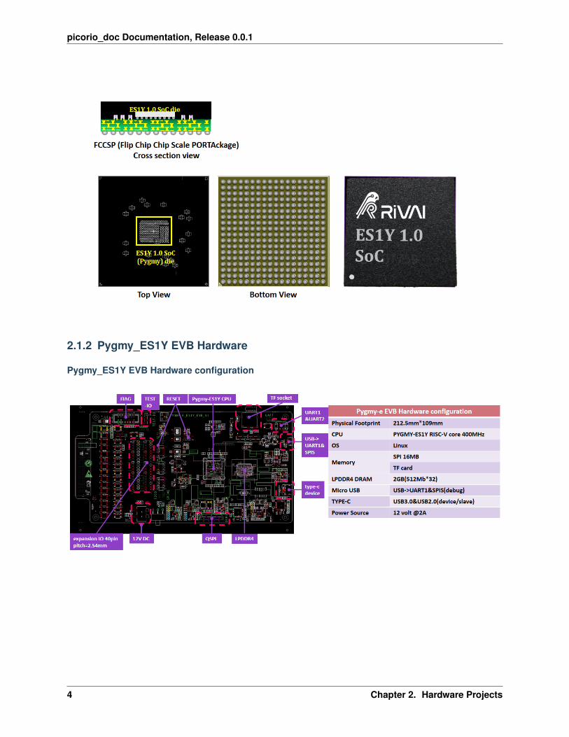
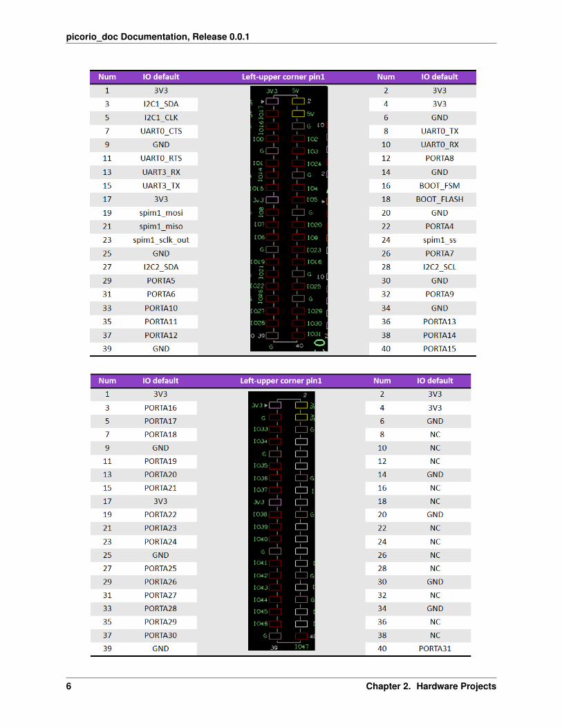
Pygmy_ES1Y EVB expansion port
Expansion port1 J28 40pin GPIOs Define
Expansion port2 J29 40pin GPIOs Define
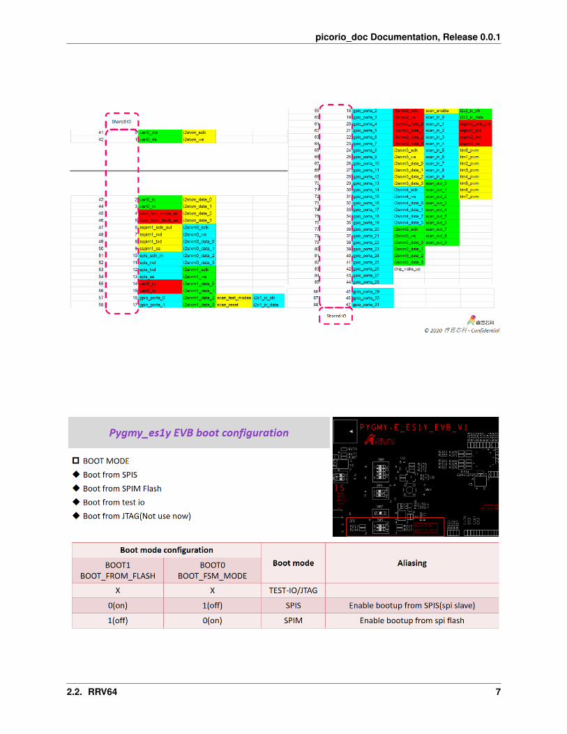
2.1.3 Pygmy_ES1Y share IO (multifunction)
2.1.4 How to use EVB?
Pygmy_ES1Y EVB boot configuration
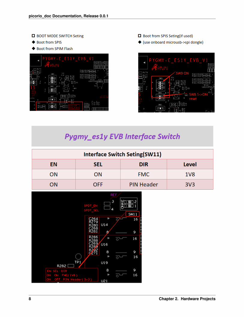
Pygmy_ES1Y EVB interface switch
Pygmy_ES1Y EVB debug
2.2 RRV64
2.2.1 Overview
RRV64 is a 64-bit RISC-V Core designed for embedded applications. It has a 5 stage in-order pipeline and multi-levelcache system including L1 and L2 I/D caches. RRV64 supports RV64IMAC instruction sets, Sv39 Virtual Addressformat, legal combinations of privilege modes in conjunction with Physical Memory Protection (PMP). It is capableof running a full-featured operating system like Linux. The core is compatible with all applicable RISC-V standards.
RRV64 is designed to be feature a very flexible memory system that includes L1 caches, L2 caches, bus interfaces,and memory maps that provide a lot of flexibility for SoC integration.
2.2. RRV64 5
picorio_doc Documentation, Release 0.0.1
6 Chapter 2. Hardware Projects
picorio_doc Documentation, Release 0.0.1
2.2. RRV64 7
picorio_doc Documentation, Release 0.0.1
8 Chapter 2. Hardware Projects
picorio_doc Documentation, Release 0.0.1
2.2. RRV64 9
picorio_doc Documentation, Release 0.0.1
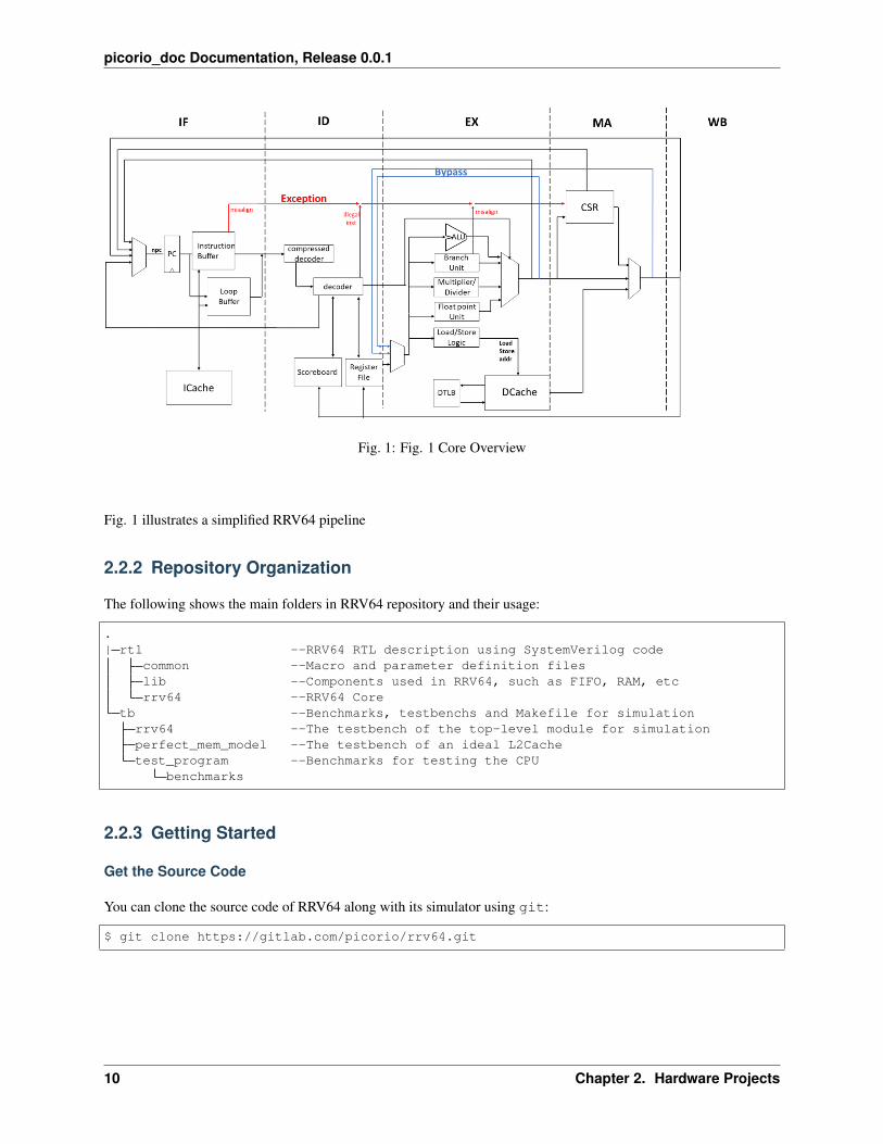
Fig. 1: Fig. 1 Core Overview
Fig. 1 illustrates a simplified RRV64 pipeline
2.2.2 Repository Organization
The following shows the main folders in RRV64 repository and their usage:
.| rtl --RRV64 RTL description using SystemVerilog code
common --Macro and parameter definition fileslib --Components used in RRV64, such as FIFO, RAM, etcrrv64 --RRV64 Core
tb --Benchmarks, testbenchs and Makefile for simulationrrv64 --The testbench of the top-level module for simulationperfect_mem_model --The testbench of an ideal L2Cachetest_program --Benchmarks for testing the CPU
benchmarks
2.2.3 Getting Started
Get the Source Code
You can clone the source code of RRV64 along with its simulator using git:
$ git clone https://gitlab.com/picorio/rrv64.git
10 Chapter 2. Hardware Projects
picorio_doc Documentation, Release 0.0.1
Prerequisites
Several tools are needed to build the project.
1. Verilator : SystemVerilog Translator and simulator
On Ubuntu, executing the following command should suffice:
$ sudo apt-get install verilator
For other OS, you can install Verilator with Git. See here for more information.
2. Gtkwave : Wave viewer
To make use of Verilator waveform tracing, you will need to have GTKwave installed.
3. RISC-V GNU Compiler Toolchain
• Choose Newlib for installation.
• For RRV64, the configuration should be: ./configure --prefix=/opt/riscv--with-arch=rv64gc --with-abi=lp64d
• To add $PATH into PATH, If you choose, say, /opt/riscv as prefix:
$ vim ~/.bashrc
append export PATH=$PATH:/opt/riscv/bin into .bashrc file, then save & exit, then
$ source ~/.bashrc
Compile & Run simulation
With VCS
To compile RRV64 with VCS
$ cd rrv64/tb$ make vcs
And then it will be compiled by VCS, to run the simulation
$ make vcs_run
The default program to be executed is Dhrystone
2.2. RRV64 11

picorio_doc Documentation, Release 0.0.1
With Verilator
Verilator is an open-source simulator, it provides verilog/systemverilog compilation function similar to VCS.
• Build RRV64 and run program with RRV64 in Verilator
$ cd rrv64/tb$ make ver
And then it will be compiled by Verilator, to run the simulation
$ make ver_run
The Dhrystone program is executed by default. You will see the execution result of Dhrystone in about oneminute.
• To change the program running in the RRV64 processor, edit the file rrv64/tb/rrv64/top.sv, input thepath to the binary file you want to execute.
Check the Waveform file
With the argument +trace after ./Vtestbench, the program will produce a waveform file with suffix .vcd inthe folder logs under its corresponding folder prefixed with sim_.
To check the waveform file, we use Gtkwave, say the .vcd file named vlt_dump.vcd:
$ gtkwave vlt_dump.vcd
2.2.4 Core design
Fetch
Instruction Fetch (rrv64_fetch) is the first pipeline stage in RRV64. This block is responsible for initiating requestsfor instruction data by sending requests to the instruction buffer and loop buffer. If one of the two buffers hits, theinstruction data will be available in the next cycle. Otherwise, the instruction buffer will send a request to I-Cacheto obtain the instruction data. Such process will take several cycles of delay. The IF module is also responsible forgenerating the address of the next instruction. It receives PC requests from other pipeline stages and arbitrates using afixed priority scheme. The modules that act as PC sources are listed below, from the highest priority to the lowest.
rrv64_csr: Sends PC on exceptions, interrupts and trap return instructions.
rrv64_execute: Sends PC when a branch instruction taken.
rrv_mem_access: Sends PC when completing a fence.i instruction and when some of CSR registers have been modi-fied. For fences, the PC request is delayed until all fetches before the fence instruction are completed and I-Cache isflushed. This is in case of any self-modifying code. For CSR modifications, delaying the PC request ensures that theCSR operation will use the correct values.
rrv_fetch: Sends PC for the normal case (next PC=PC+4 or PC+2 for compressed instructions), immediate jumps andregister jumps.
12 Chapter 2. Hardware Projects
picorio_doc Documentation, Release 0.0.1
Interfaces
if2ic/ic2if: These interfaces are used for sending PC fetch requests from IF to instruction buffer and loop buffer. Thisinterface uses an enable signal to send requests. This enable signal is held high until a response is received. There are2 signals in if2ic interface:
1. pc: The address of the requested instruction.
2. valid: If this request is valid.
On the response side (ic2if), the main signals are:
1. inst/rvc_inst: The instruction data.
2. valid: Whether this response is valid.
3. is_rvc: Whether the instruction is RVC or not.
4. excp_cause: Contains the exception cause of the instruction, if any.
5. excp_valid: Whether this instruction was found to have an exception.
if2id: This interface contains all the data that is passed from IF to ID. It works using a valid/ready handshake. Thereare 2 signals in this interface.
1. inst: The instruction data.
2. pc: The PC of the instruction.
cs2if_npc/ma2if_npc/ex2if_npc/id2if_npc: These interfaces are used for sending PC redirection request to IF. Theywork using a valid/ready handshake. There are 2 signals in these interfaces.
1. pc: The new value of the PC register.
2. valid: Whether the request is valid.
Decode
Decode (ID) is the second stage in RRV64’s pipeline. It receives instruction data from the IF stage and hold it ifnecessary, expands C-extension instructions, decodes instruction data to set the control signals, and sends read requeststo the regfile. When encountering an illegal instruction, the decoder will generate an exception signal, which will behandled when the current instruction reaches the MA stage.
The RRV64 implements the standard compressed extension to the RISC-V architecture, which allows for 16-bit, inaddition to the normal 32-bit instruction size. To handle this new size of instructions, ID contains a submodule thattakes the 16-bit instructions and expand it to its 32-bit equivalent. This module acts as the first layer of decoding.
After ID has the final instruction data, either the expanded compressed instruction, or the initial instruction data, it willbegin to decode the instruction to determine how to set the control signals that will be used throughout the pipeline. Inthe RTL, you can find a case statement that will call different functions depending on the instruction’s opcode, funct7field, funct5 field, etc. These functions will output the appropriate control signals. If the instruction needs to read theregister, ID will asynchronously read the registers in rrv64_regfile (IRF). Since IRF doesn’t contain a real entry for x0,ID will instead substitute this read with a hardwired 0 signal.
If ID decodes its current instruction as a JAL instruction, it will calculate the destination address and send a redirectrequest to the IF stage. If it is a fence_i, mret, or a csr operation on the PMP related registers, the ID will stall the IFstage until the instruction is retired.
There is a Regfile Scoreboard in this stage. Its purpose is to track which registers still have pending writes. This isused to resolve data hazards. When ID decodes that its instruction will eventually write to the regfile, it indexes intothe scoreboard using rd (the index of the destination register) and marks that entry, to signal that there is a pendingwrite, and thus a possible data hazard. When that instruction eventually writes to the regfile, that scoreboard entry is
2.2. RRV64 13

picorio_doc Documentation, Release 0.0.1
cleared. If ID has an instruction and with one, or both, of its source registers indicating pending writes, it will use thedata pushed forward from EX stage or wait for the data retrieved from the memory.
Interfaces
id2irf: This interface is for requesting the data in the IRF. There are 4 signals.
1. rs1_addr: The address of source register 1.
2. rs2_addr: The address of source register 2.
3. rs1_re: Control signal. High when read to rs1_addr is valid.
4. rs2_re: Control signal. High when read to rs2_addr is valid.
id2ex: This interface contains all the data passed from ID to EX. It works on a valid/ready handshake. There are 6signals in this interface.
1. pc: The PC of the instruction.
2. inst: The instruction data.
3. rs1_addr: The address of source register 1.
4. rs2_addr: The address of source register 2.
5. is_rvc: Signals whether this instruction is RVC, used to calculate npc in EX and MA stage, if needed.
ex2id_bps/ma2id_bps: These interfaces are used for data forwarding: send the execution result of the EX/MA stageback to the EX stage to solve data hazard. There are 4 signals in this interface.
1. valid_addr: Indicating whether the address of register accessing or memory accessing is valid.
2. valid_data: Indicating whether the data of register accessing or memory accessing is valid.
3. addr: The address of register accessing or memory accessing. Used to compare with the address to be accessedby the instruction in the ID stage.
4. data: The data in register accessing or memory accessing.
Execute
The execute stage is responsible for calculations and sending memory requests to the LSU. This stage consists of anarithmetic and logic unit (ALU), a pair of multi-cycle multiplier and divider, a branch address calculation unit and aload/store address calculation unit.
ALU: The ALU is responsible for additions, subtractions, shifts, data comparisons (for branches and slt instructions),and bit-wise logical operations (AND, OR, XOR). The ALU is fed with the operands as well as the operation type.The logic in ALU is purely combinational.
Multiplier: The multiplier is used for multiplications. It is fed the operands as well as the multiplication type. Thestart_pulse input of the multiplier is set to 1 for 1 cycle to trigger the multiplication operation. The complete output isset to 1 when the multiplication is done. For multiplications where only the lower 64 bits of the result are needed, thecalculation completes in the same cycle the start_pulse is set to 1. For multiplications where the upper 64 bits of theresult are needed, the calculation completes in 3 cycles.
Divider: The divider is used for division operations. The divider is fed with the operands as well and the division type.The divider triggers the calculation when start_pulse input is set to 1. The complete output is set to 1 when DIV isdone. DIV takes 17 cycles to accomplish a division operation.
The target address of the branch and the address of load/store instructions are calculated by the branch address cal-culation unit. For a branch instruction, if the branch is taken, a flush signal will be sent to IF and ID to “flush” the
14 Chapter 2. Hardware Projects

picorio_doc Documentation, Release 0.0.1
instructions in those stage, and a redirection signal will be sent to IF and the value of PC will change accordingly.For load/store instruction, the memory access request will be sent to D-Cache, so if D-Cache hits, we can the get thememory access result at MA stage in the next cycle.
Interfaces
ex2ma: This interface contains all the data passed from EX to MA. It works on a valid/ready handshake. There are 6signals in this interface.
1. pc: The PC of the instruction.
2. inst: The instruction data.
3. ex_out: The result of EX’s calculation.
4. rd_addr: The address of destination register 1, if any.
5. csr_addr: The address of csr register, if any.
6. is_rvc: Whether this instruction is RVC.
ex2dc: This is the interface between EX and D-Cache, used for sending memory requests. It uses a valid/readyhandshake. There are 5 signals in this interface.
1. rw: 1 if the request is a write, 0 if it is a read.
2. mask: The byte mask for Store operation.
3. addr: The memory request address.
4. wdata: The write data of the memory request.
5. width: The width of the operand of Load/Store operation.
Memory Access
This stage is responsible for receiving memory responses from D-Cache, interfacing with rrv_csr (CSR), sendingredirection requests to IF in certain cases, and committing instructions and writing data to Register Files.
For load and store instructions, MA will receive memory responses from D-Cache. Only 1 memory response isaccepted per instruction. Loads will respond with the data read from memory, while stores will respond with 0 data.The data will be pushed forward to the ID stage through the bypass network to solve possible data hazard.
For CSR instructions, the MA stage will read and write the CSR Registers.
For fence or those csr operations on the PMP related registers, MA will send a npc signal to the IF stage to release thestall state of the IF, ID and EX stages.
For instructions with destination register and without any exceptions, it is at MA stage that the result will write to theregfile. Regfile writes are synchronous.
2.2. RRV64 15

picorio_doc Documentation, Release 0.0.1
Interfaces
dc2ma: This interface is the memory response interface between D-Cache and MA. There are 4 signals in this inter-face.
1. rdata: The read data requested by load instructions.
2. excp_valid: Signals whether the memory access operation cause an exception (e.g. violated a PMP check).
3. excp_cause: Contains the exception cause of the instruction, if any.
4. valid: Whether the response is valid.
ma2cs/ma2cs_ctrl: These interfaces are used by MA for sending read/write requests to CSR. The ma2cs_ctrl is forcontrolling transactions with CSR. In ma2cs_ctrl, there are 3 signals in this interface:
1. csr_op: CSR operation type. It can be set to RRV64_CSR_OP_RW (read and write), RRV64_CSR_OP_RS(read and set), RRV64_CSR_OP_RC (read and clear) and CSR_OP_NONE if MA does not have a request toCSR.
2. ret_type: Return instruction type (mret or uret). It will be set to RET_TYPE_NONE if the instruction is noteither of the ret type instructions mentioned.
3. is_wfi: Set to 1 if the instruction is a WFI instruction.
For ma2cs, there are 5 signals in this interface:
1. pc: PC of the current instruction. Used mainly for exception handling.
2. csr_addr: Request CSR address.
3. csr_wdata: Data used for do some calculation with data in CSR, the calculation result will be written back tothe CSR.
4. rs1_addr: rs1 address of the instruction. Used for checking if the CSR operation should be considered a write.
5. mem_addr: Memory address of the load or store instruction. Used for updating the MTVAL CSR on load/storePMP exceptions.
ma2irf: This interface is used by MA to send regfile writes to IRF. Writes will be validated using an active high writeenable signal. Including the enable signal, there are 3 signals in this interface:
1. rd: Write data.
2. rd_addr: Regfile write address.
3. rd_we: Write enable.
Instruction Buffer
The instruction buffer is mainly used to prefetch instructions from L1 Cache. In addition to the instruction requestedby the IF, the instruction buffer also fetches the instructions of the next two cache lines. If the execution flow issequential, or there is a forward jump whose span is less than two cache lines, the instruction buffer will hit and returnthe instruction data within one cycle since we have already fetch it before. When a branch or jump instruction is takenand the instruction corresponding to the destination address is not currently in instruction buffer, the instruction bufferwill be flushed and send a request to ICache.
16 Chapter 2. Hardware Projects

picorio_doc Documentation, Release 0.0.1
Loop Buffer
Loop buffer is a high speed D-Cache type memory that is used for holding up to 64 of the most recently fetchedinstructions. It is maintained by the IF stage of the pipeline. If a branch instruction is taken, we can first check theloop buffer to see if the instruction exists. If the loop buffer hits, the instruction data will be returned to IF within acycle. If not, the loop buffer will wait for the instruction data be fetched from instruction buffer or L1 Cache and usethis instruction to replace the oldest instruction in loop buffer.
Address Translation
To support an operating system, RRV64 features full hardware support for address translation via a Memory Man-agement Unit (MMU). It has separate configurable data and instruction TLBs. The TLBs are fully set-associativememories. On each instruction and data access, they are checked for a valid address translation. If none exists,RRV64’s hardware PTW queries the main memory for a valid address translation. The replacement strategy of TLBentries is Pseudo Least Recently Used (LRU).
Both instruction cache and data cache are virtually indexed and physically tagged and fully parametrizable. Theaddress is split into page offset (lower 12 bit) and virtual page number (bit 12 up to 39). The page offset is used toindex into the cache while the virtual page number is simultaneously used for address translation through the TLB. Incase of a TLB miss the pipeline is stalled until the translation is valid.
Exception Handling
Exceptions can occur throughout the pipeline and are hence linked to a particular instruction. The first exceptioncan occur during instruction fetch when the PTW detects an illegal TLB entry or the address is not aligned. Duringdecoding, exceptions can occur when the decoder detects an illegal instruction. As soon as an exception has occurred,the corresponding instruction is marked and auxiliary information is saved. Such excepting instruction will be handledby the exception handler at the MA stage.
Interrupts are asynchronous exceptions, in RRV64, they are synchronized to a particular instruction. Like exception,the interrupt signal will be processed in the MA stage.
Privileged Extensions
The privileged specification defines more CSRs governing the execution mode of the hart. The base supervisor ISAdefines an additional interrupt stack for supervisor mode interrupts as well as a restricted view of machine mode CSRs.Accesses to these registers are restricted to the same or a higher privilege level.
CSR accesses are executed in the MA stage. Furthermore, a CSR access can have side-effects on subsequent instruc-tions which are already in the pipeline e.g. altering the address translation infrastructure. This makes it necessary tocompletely flush the pipeline on such accesses.
2.3 Cache
2.3.1 Cache overview
So far, the RRV64 core is equipped with private L1 instruction & data cache and unified L2 cache, the coherent L1data cache is in progress.
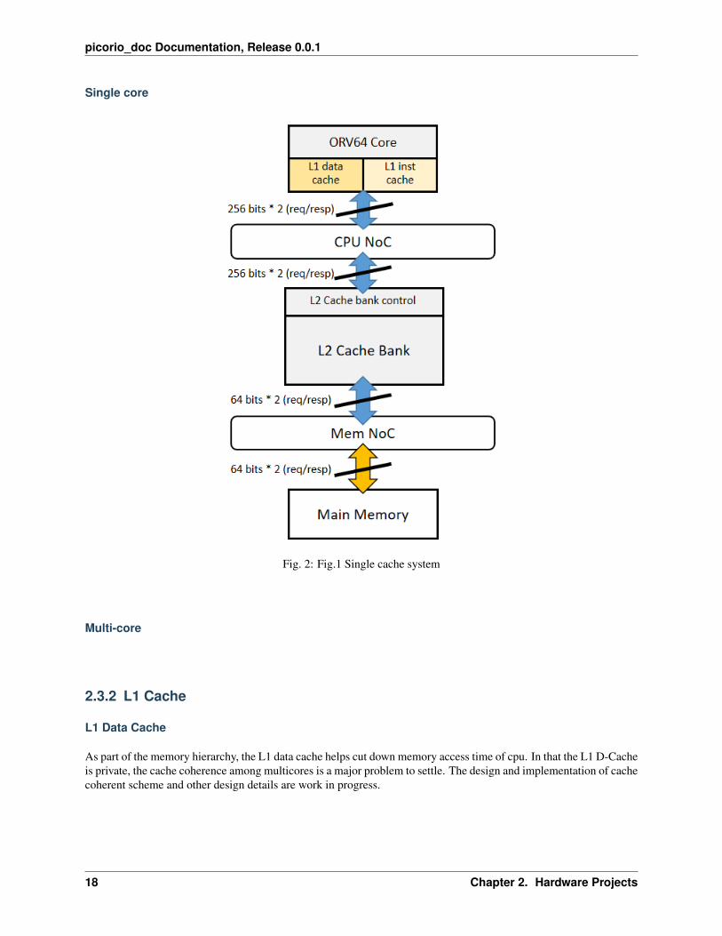
The overall design of our internal memory hierarchy is illustrated in following blockdiagram.
2.3. Cache 17
picorio_doc Documentation, Release 0.0.1
Single core
Fig. 2: Fig.1 Single cache system
Multi-core
2.3.2 L1 Cache
L1 Data Cache
As part of the memory hierarchy, the L1 data cache helps cut down memory access time of cpu. In that the L1 D-Cacheis private, the cache coherence among multicores is a major problem to settle. The design and implementation of cachecoherent scheme and other design details are work in progress.
18 Chapter 2. Hardware Projects

picorio_doc Documentation, Release 0.0.1
Fig. 3: Fig.2 Multi-core cache system
2.3. Cache 19

picorio_doc Documentation, Release 0.0.1
Parameter
The parameter of L1 data cache is as follows:
Cache capacity Cache line numbers Cache line capacity Mapping method32 KBytes 512 32 Bytes 2-way set associative
L1 Instruction Cache
As part of memory hierarchy, the L1 instruction cache helps cut down the latency of cpu instruction fetching.
The parameter of L1 instruction cache is as follows:
Cache capacity Cache line numbers Cache line capacity Mapping method8 KBytes 128 32 Bytes 2-way set associative
2.3.3 L2 Cache
Overview
The L2 cache is a 256KB, 4-bank, 4-way set associative shared L2 cache. The latency of L2 cache is 4 cycles athit. The L2 cache RAM reading and writing processes are pipelined into 4 stages for less RAM access and higherfrequency. The L2 cache is designed as a non-blocking cache which can handle hit-under-miss and miss-under-missusing the Missing Status Holding Registers (MSHRs). With non-blocking L2 cache design, memory system canexecute out-of-order and more latency can be hidden.
Parameter
The parameter of L1 data cache is as follows:
Cache capacity Cache line numbers Cache line capacity Mapping method256 KBytes 512 32 Bytes 4-way set associative
L2 cache pipeline
The L2 is designed as 4-stage-pipeline for low power and high frequency. In the first 3 stages, valid, tag, lru, dirty anddata RAMs are serially checked, which means some of the RAMs are not needed to be accessed if the information gotfrom previous stages tells the control logic not to.
The Missing Status Holding Registers lie in the stage 4, which has the ability to hold multiple cache missed request tothe next level memory, without blocking the whole pipeline. This is a key feature for Out-of-Order memory system.
20 Chapter 2. Hardware Projects

picorio_doc Documentation, Release 0.0.1
Fig. 4: Fig.1 L2 cache bank connection
Fig. 5: Fig.2 L2 cache pipeline overview
2.3. Cache 21

picorio_doc Documentation, Release 0.0.1
2.4 Contributing
We highly appreciate community contributions. If you want to do contribution to the project, please:
• Create your own branch to commit your changes and then open a Pull Request.
• Split large contributions into smaller commits addressing individual changes or bug fixes. Only include onechange in per commit.
• Write meaningful commit messages. For more information, please check out the commit guide.
• If asked to modify your changes, do fixup your commits and rebase your branch to maintain a clean history.
2.4.1 Commit guide
• Create your branch to commit your changes and then create a Pull Request.
• Separate subject from body with a blank line.
• Capitalize the subject line.
• Use the present tense (“Add feature” not “Added feature”).
• Use the body to explain what and why and how.
Component DescriptionPygmy_ES1YBoard
Pygmy_ES1Y EVB User Guide
RRV64 Core RRV64 core used in PicoRio: a 64-bit, single in-order issue, 5-stage-pipeline 64-bit RISC-Vcore.
Graphics Collection of display pipeline in PicoRio™. This includes the GPU, display core, and videoencoder and decoder.
Cache System Private L1 instruction & data cache and unified L2 cache.System Control System control related features and unitsIO Collection of input and output interfaces in PicoRio hardware.
The overall PicoRio™ hardware blockdiagram (future work included):
22 Chapter 2. Hardware Projects

picorio_doc Documentation, Release 0.0.1
2.4. Contributing 23

picorio_doc Documentation, Release 0.0.1
24 Chapter 2. Hardware Projects

CHAPTER
THREE
SOFTWARE PROJECTS
This section describes the software projects which PicoRio supports. We put all projects in a dashboard, and list outthe current developing status of them.
3.1 Firmware
3.1.1 Debug socket introduction
Debug-socket
Debug-socket is proxy running on host to interact with target, the functionality of debug-socket in software develop-ment, as shown in the following picture.
Fig. 1: Fig.1 Socket debug in SW development
According to the riscv-debug specification, if any kernel contains standard debug modules, simply follow the: “RISC-V external debugging support version xxx”. For standard debug module:
25

picorio_doc Documentation, Release 0.0.1
Fig. 2: Fig.2 RISC-V debug overview
26 Chapter 3. Software Projects

picorio_doc Documentation, Release 0.0.1
We choose to use a software-based debug socket instead of a standard debug module to implement the debug function,both of which have the same effect and can be used for debugging of the soc. For our debug-socket, see debug-socketconnections overview.
Basically, the debug-socket implements basic functions required by gdb, with the help of hardware-provided break-point, watchpoint, trace buffer, and many other features.
Debug-socket supported command list
The full-stack debug tool development is under way, you can use the raw debug-socket interface to debug for now.Debug socket offers a big list of commands, however the following commands are the ones used most frequently:
Command Usage Functionb0 b0 addr set a breakpoint at hw breakpoint 0 with addrb1 b1 addr set a breakpoint at hw breakpoint 1 with addrb2 b2 addr set a breakpoint at hw breakpoint 2 with addrb3 b3 addr set a breakpoint at hw breakpoint 3 with addrd0 d0 disable breakpoint at hw breakpoint 0d1 d1 disable breakpoint at hw breakpoint 1d2 d2 disable breakpoint at hw breakpoint 2d3 d3 disable breakpoint at hw breakpoint 3wp (not supported for now) wp show watchpoint configurebp bp show breakpoint configurec c continue to runstall stall make cpu stallstep N step N run next N instructionsgpr(not supported for now) gpr print all general purpose registerq q quit debug-socketwb_pc wb_pc show current excute instruction pcif_pc if_pc show current fetch instruction pcminstret minstret show m-mode excuted instruction countmstatus mstatus show mstatus valuemcause mcause show mcause valuemepc mepc show mepc valuemip mip show mip valuemie mie show mie valuehpmcounter_3~hpmcounter_10 hpmcounter_3 hpmcounter_4 hpmcounter_5 hpmcounter_6 hpmcounter_7 hpmcounter_8 hpmcounter_9 hpmcounter_10 show PMU counter valuesdump dump 0x00f00000 0x00f00080 rb/dma dump content from start address to end addressread read 0x00f00000 rb/dma read content from specified address, rb for device register & dma for memorywrite write 0x00f00008 1 rb/dma write value to specified address, rb for device register & dma for memoryuart1 uart1 show uart1 cfggpio gpio show gpio cfgrtc rtc show rtc cfgwdt wdt show wdt cfgi2c0 i2c0 show i2c controller’s cfg
3.1. Firmware 27

picorio_doc Documentation, Release 0.0.1
Fig. 3: Fig.3 Debug socket connection overview
28 Chapter 3. Software Projects

picorio_doc Documentation, Release 0.0.1
Classical debug process
When encounter some error in program, you can use debug-socket to debug the program:
1. type ‘minstret’ twice to analysis if the CPU is stall or not, if the two values of minstret is the same value, the CPUis stalled
: minstretDo Read to Addr 0x1002b0 (minstret), Got Data 0x2409734fPlease enter command: (All Data in HEX no matter 0x is added or not): minstretDo Read to Addr 0x1002b0 (minstret), Got Data 0x240aa177Please enter command: (All Data in HEX no matter 0x is added or not):
2. if the CPU is not stalled, type ‘wb_pc’
: wb_pcDo Read to Addr 0x100258 (wb_pc), Got Data 0x80009430Please enter command: (All Data in HEX no matter 0x is added or not):
3. use ‘b0 addr’ to set a breakpoint, the program will stop when run into addr
: b0 80008e48add breakpoint0, pc_addr = 0x80008e48Please enter command: (All Data in HEX no matter 0x is added or not):
4. then, you can use ‘read addr dma’ to check some var value
: read 800102c4 dmaDo Read to Addr 0x800102c4, Got Data 0x6ffffffffPlease enter command: (All Data in HEX no matter 0x is added or not):
5. type ‘step N’ to run N instructions
: step 10pc = 0x80000300pc = 0x80000304pc = 0x80000308pc = 0x8000030cpc = 0x80000310pc = 0x80000314pc = 0x80000318pc = 0x8000031cpc = 0x80000320pc = 0x80000324Please enter command: (All Data in HEX no matter 0x is added or not):
6. re-check some var
: read 800102c4 dmaDo Read to Addr 0x800102c4, Got Data 0x6ffffffffPlease enter command: (All Data in HEX no matter 0x is added or not):
3.1. Firmware 29

picorio_doc Documentation, Release 0.0.1
7. continue to run until run into the breakpoint again
: cContinuePlease enter command: (All Data in HEX no matter 0x is added or not):
8. disable breakpoint
: d0del hw breakpoint1Please enter command: (All Data in HEX no matter 0x is added or not):
9. continue
: cContinuePlease enter command: (All Data in HEX no matter 0x is added or not):
3.1.2 ES1Y SDK v1.0 Introduction
ES1Y Software Development Kit is used in linux platform at present and it will support much more host OS, e.g.windows later. The SDK provides freertos APIs for customers’ application development, what’s more, there are somesystem test demos included in the SDK so as to help the new customers get on hand quickly.
1. Getting start
• In this chapter, we need prepare development environment and know how to make the binary running on ES1YSoC, and then rvSDK provide straightforward tools for debugging.
1. Init SDK
Follow the README.md file at SDK v1.0 root dir firstly.
2. Compile & Run
– Build the gcc toolchain
$ cd build$ make gcc
– Build the fesvr & debug proxy
$ make fesvr$ make driver
– Build freertos and application code
# clean if needed$ make freertos-clean$ make freertos
– Run vivado to use FPGA as a debug tool, at the same time, run debug proxy
30 Chapter 3. Software Projects

picorio_doc Documentation, Release 0.0.1
# this command only need execute once time in the whole debug→˓process$ make run-vivado # or shortly 'make rv'
– Download and run FreeRTOS firmware through debug proxy
$ make run-rtos # or shortly 'make rvt'# when you finish your debug and want to exit# use Ctrl+C Ctrl+C(that is: input Ctrl+C twice).
– You can use this one command below instead of steps above to simplify build process
$ make freertos-all
– One additional command is provided to speed up debuging after edit source code
# this command equal to make freertos && make run-rtos$ make re-comp-run-rtos # or shortly 'make rvrt'
– The default code in rvSDK v1.0 will startup two tasks, which one print ‘TEST’ per second and the other one print ‘DEMO’ every 2 seconds, after do some IO test:
*************************************************
Welcome enter FreeRTOS on pygmy_e platform
*************************************************
TEST DEMO for IO functions ...
TEST IO functions done ...------- TEST -------
Demo task ...------- Demo -------------- TEST -------------- TEST -------------- Demo -------------- TEST -------------- TEST -------------- Demo -------
3. Debug
– Console by UART
* Please read the other document that introduces usb-uart dongle connection betweenhost & target.
* The proper UART baudrate & other configuration is 500000, 8n1 for print debug-ging.
– Command Line Interface(CLI)
* There are some limitations for debugging CLI in rvSDK v1.0 with debug-spi-base.o, anyway, we will provide more abundant debugging tool in future.1. Debug tool startup interface
$ cd software/host/driver/pygmy_e$ ./debug-socket.o
(continues on next page)
3.1. Firmware 31
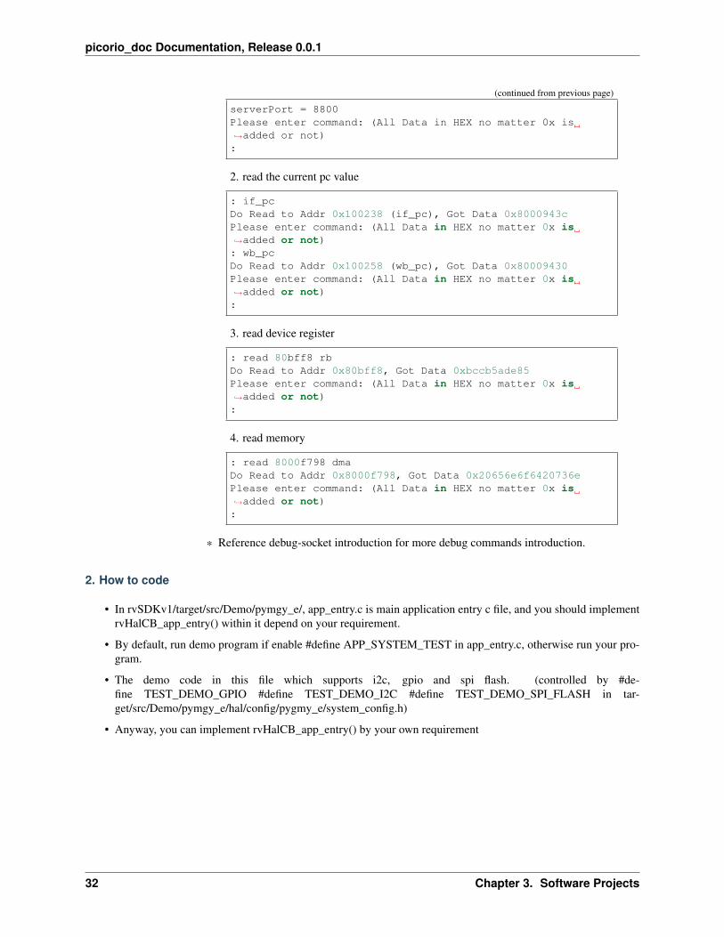
picorio_doc Documentation, Release 0.0.1
(continued from previous page)
serverPort = 8800Please enter command: (All Data in HEX no matter 0x is→˓added or not):
2. read the current pc value
: if_pcDo Read to Addr 0x100238 (if_pc), Got Data 0x8000943cPlease enter command: (All Data in HEX no matter 0x is→˓added or not): wb_pcDo Read to Addr 0x100258 (wb_pc), Got Data 0x80009430Please enter command: (All Data in HEX no matter 0x is→˓added or not):
3. read device register
: read 80bff8 rbDo Read to Addr 0x80bff8, Got Data 0xbccb5ade85Please enter command: (All Data in HEX no matter 0x is→˓added or not):
4. read memory
: read 8000f798 dmaDo Read to Addr 0x8000f798, Got Data 0x20656e6f6420736ePlease enter command: (All Data in HEX no matter 0x is→˓added or not):
* Reference debug-socket introduction for more debug commands introduction.
2. How to code
• In rvSDKv1/target/src/Demo/pymgy_e/, app_entry.c is main application entry c file, and you should implementrvHalCB_app_entry() within it depend on your requirement.
• By default, run demo program if enable #define APP_SYSTEM_TEST in app_entry.c, otherwise run your pro-gram.
• The demo code in this file which supports i2c, gpio and spi flash. (controlled by #de-fine TEST_DEMO_GPIO #define TEST_DEMO_I2C #define TEST_DEMO_SPI_FLASH in tar-get/src/Demo/pymgy_e/hal/config/pygmy_e/system_config.h)
• Anyway, you can implement rvHalCB_app_entry() by your own requirement
32 Chapter 3. Software Projects

picorio_doc Documentation, Release 0.0.1
3. Programming API
• Freertos API
– we can easily get the help from https://www.freertos.org/FreeRTOS-quick-start-guide.html
3.1.3 ES1Y API
OS API
The official FreeRTOS API references can be found here: https://www.freertos.org/a00106.html
UART API
Only support module init and printf functions for now, more functions is under developing.
/********************************uart
*********************************//*!
* @discussion initialize uart module.
*/void __rvHal_uart_init(void);
/*!
* @discussion print log through uart.
* @param fmt fmt string.
* @param ... params corresponding to % in fmt string.
* this is a simplified version printf of standard printf in libc,
* only support below format params:
* %d, %u, %ld, %lu, %lld, %llu, %o, %x, %lo, %lx, %llo, %llx, %s, %c, %%
* and also support width and padding in params above
*/int printf(const char* fmt, ...);
GPIO API
GPIO API is in the following code snippet
/********************************gpio
*********************************/
struct irq_gpio_handler_t{
void *context;void (*hook)(void *context);
};
struct gpio_desc{
unsigned int pin;struct irq_gpio_handler_t handler;
};
(continues on next page)
3.1. Firmware 33
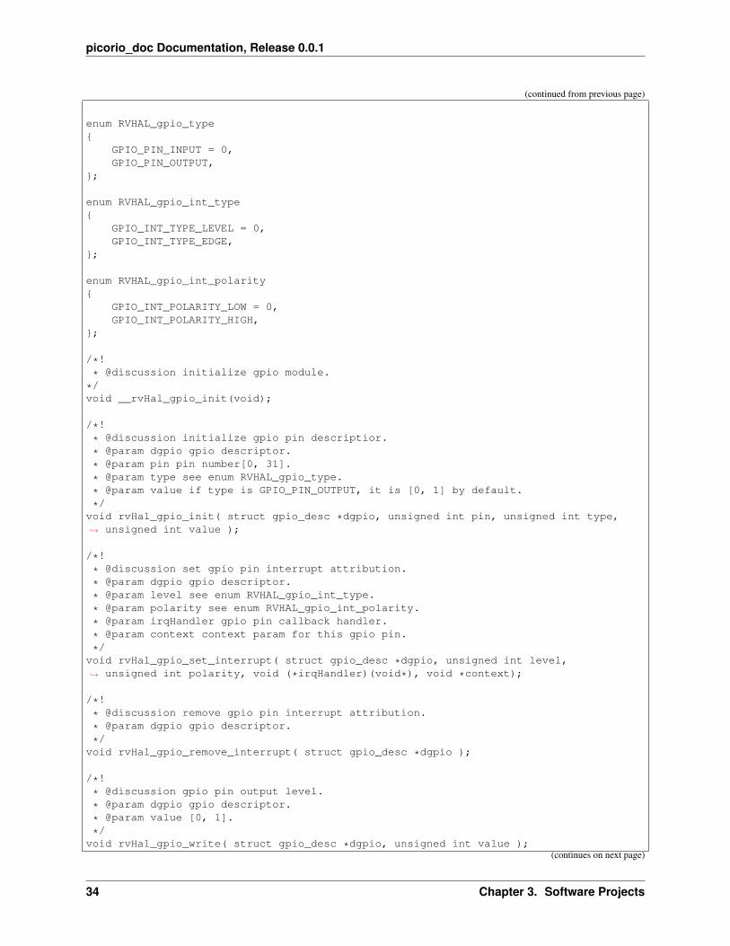
picorio_doc Documentation, Release 0.0.1
(continued from previous page)
enum RVHAL_gpio_type{
GPIO_PIN_INPUT = 0,GPIO_PIN_OUTPUT,
};
enum RVHAL_gpio_int_type{
GPIO_INT_TYPE_LEVEL = 0,GPIO_INT_TYPE_EDGE,
};
enum RVHAL_gpio_int_polarity{
GPIO_INT_POLARITY_LOW = 0,GPIO_INT_POLARITY_HIGH,
};
/*!
* @discussion initialize gpio module.
*/void __rvHal_gpio_init(void);
/*!
* @discussion initialize gpio pin descriptior.
* @param dgpio gpio descriptor.
* @param pin pin number[0, 31].
* @param type see enum RVHAL_gpio_type.
* @param value if type is GPIO_PIN_OUTPUT, it is [0, 1] by default.
*/void rvHal_gpio_init( struct gpio_desc *dgpio, unsigned int pin, unsigned int type,→˓ unsigned int value );
/*!
* @discussion set gpio pin interrupt attribution.
* @param dgpio gpio descriptor.
* @param level see enum RVHAL_gpio_int_type.
* @param polarity see enum RVHAL_gpio_int_polarity.
* @param irqHandler gpio pin callback handler.
* @param context context param for this gpio pin.
*/void rvHal_gpio_set_interrupt( struct gpio_desc *dgpio, unsigned int level,→˓ unsigned int polarity, void (*irqHandler)(void*), void *context);
/*!
* @discussion remove gpio pin interrupt attribution.
* @param dgpio gpio descriptor.
*/void rvHal_gpio_remove_interrupt( struct gpio_desc *dgpio );
/*!
* @discussion gpio pin output level.
* @param dgpio gpio descriptor.
* @param value [0, 1].
*/void rvHal_gpio_write( struct gpio_desc *dgpio, unsigned int value );
(continues on next page)
34 Chapter 3. Software Projects

picorio_doc Documentation, Release 0.0.1
(continued from previous page)
/*!
* @discussion gpio pin input level.
* @param dgpio gpio descriptor.
* @return value [0, 1].
*/unsigned int rvHal_gpio_read( struct gpio_desc *dgpio );
/*!
* @discussion toggle gpio pin output level.
* @param dgpio gpio descriptor.
*/void rvHal_gpio_toggle( struct gpio_desc *dgpio );
Projects Project DescriptionDebugsocket
Debug-socket is proxy running on host to interact with target, the functionality of debug-socket in soft-ware development.
ES1YSDK
ES1Y SDK v1.0 provides freertos for customers’ application development, what’s more, there are somesystem test demos included in rvSDK so as to help the new customers get on hand quickly.
ES1YAPI
Includes OS API, UART API, GPIO API
3.2 V8-RISCV
Welcome to the v8-riscv wiki
This is an on-going project to enhance the RISC-V backend for the V8 JavaScript Engine. The initial port has beenupstreamed (https://chromium.googlesource.com/v8/v8.git/). The RISC-V backend is fully functional and is able torun the full test suites as well has common benchmarks, but it still needs improvements for improving performanceand adding features. We have established a sustainable porting methodology and development best practices, such thatwe feel confident to invite broader community participation. We welcome you to join our development effort. Plentyof support is still needed for a complete and high-performing V8 on RISC-V.
This repo will be the community home even though it is now available upstream. This provides us a shared space fordeveloping larger changes here before pushing them upstream, as well as a stable branch that will always work forRISC-V, as upstream may still break the RISC-V port from time to time. For general V8 information, see V8 Dev.The rest of the wiki is specific to the RISC-V V8 backend.
RISC-V ISA specification is found here, and RISC-V standard ABI can be found here.
3.2.1 Getting Started
• Get the source
• Cross-compiled build (running on QEMU/HiFive)
• Simulator build (for developers running on x86)
• Run tests
• Build RPM packages
3.2. V8-RISCV 35

picorio_doc Documentation, Release 0.0.1
3.2.2 Project Management
• Project roadmap
• Testing status
• Work groups
• [[Upstream Workflow]]
3.2.3 For Developers
• Setup VSCode
• How to contribute
• How to debug V8
3.2.4 RISC-V Backend Design Doc
• Understand V8 backend architecture
• How to add a new instruction
• How to develop a new backend
3.2.5 Community operation
• Join our Slack
• Attend our bi-weekly developer Zoom Meeting
| Meeting Info | Description | |-|-| | Next meeting | 17/03/2021 (US) | | Time | every other Wednesdays 5pm PT(Thursdays 9am Beijing Time) | | Meeting ID| 876 4151 0603 | | Passcode | 714793 | | Meeting agenda | Meetingagenda (03/03) | | Last meeting minutes | Meeting minutes (03/03)|
• Content sharing
ProjectsDevel-opmentState
Project Description Link
Firmware ES1Y Firmware includes Debug socket, ES1Y SDK and ES1Y API. https://gitlab.com/picorio/picorio-software
V8 V8 is a commonly used JavaScript engine in popular web browsers. Pico-Rio provides support for RISC-V V8.
https://github.com/v8-riscv/v8/
ChromiumOS
Chromium OS is a open-source web browser with strong web applica-tion support and rich software ecosystem. This project is RISC-V port ofChromium OS, and is in development.
36 Chapter 3. Software Projects


![interoperability.blob.core.windows.netMS-DOC]-181211.… · Web view[MS-DOC]: Word (.doc) Binary File Format. Intellectual Property Rights Notice for Open Specifications Documentation](https://img.pdfslide.net/doc/110x75/5e71bbb548f2395cba128f88/ms-doc-181211-web-view-ms-doc-word-doc-binary-file-format-intellectual.jpg)
![interoperability.blob.core.windows.netMS-DOC] … · Web view[MS-DOC]: Word (.doc) Binary File Format. Intellectual Property Rights Notice for Open Specifications Documentation](https://img.pdfslide.net/doc/110x75/5e9968a82ad52c376f28b869/ms-doc-web-view-ms-doc-word-doc-binary-file-format-intellectual-property.jpg)