Embed Size (px)
Citation preview
21-31200-200-00x
Pictures of the Bruce A
Calandria and Shield Tankduring fabrication
at Canadian Vickers
photos byKen Jay, AECL
1971 - 1973
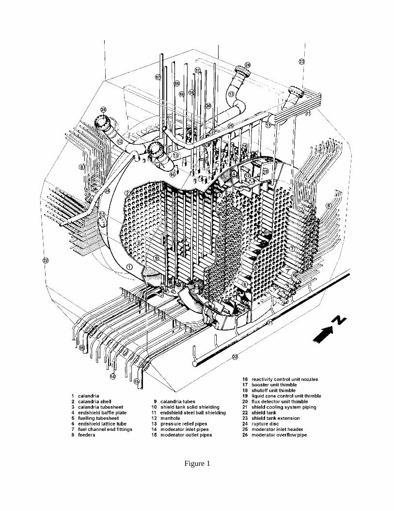
Figure 1
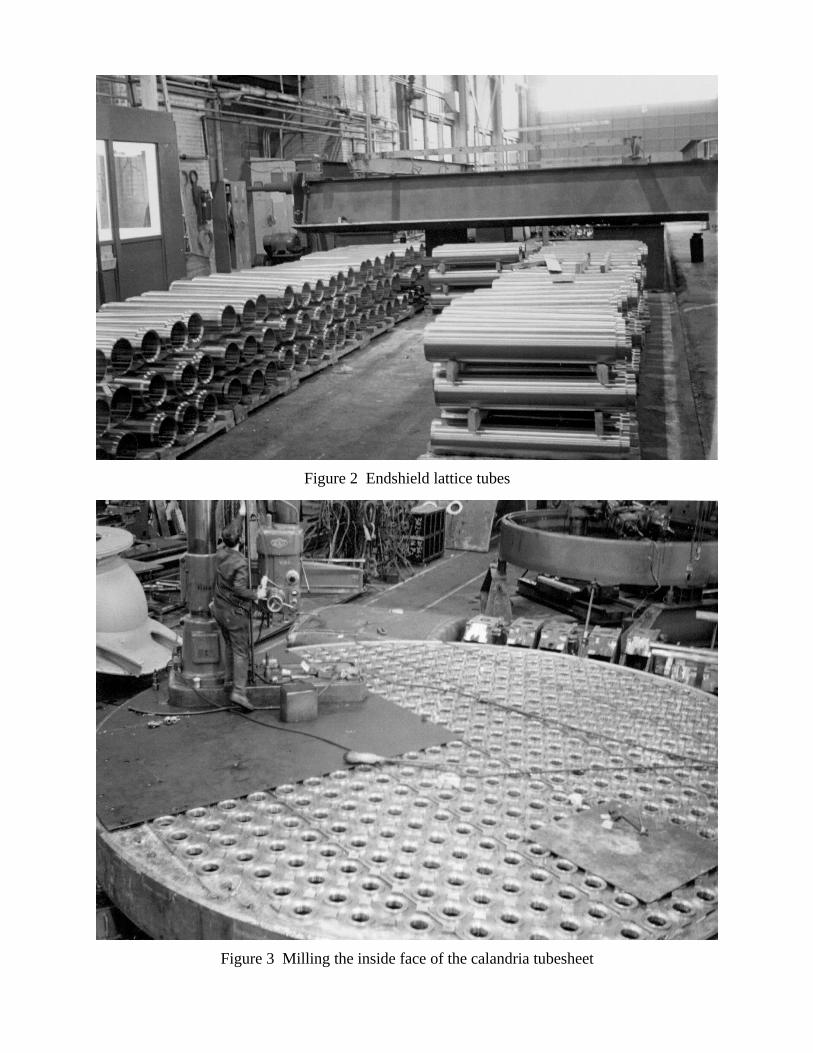
Figure 2 Endshield lattice tubes
Figure 3 Milling the inside face of the calandria tubesheet
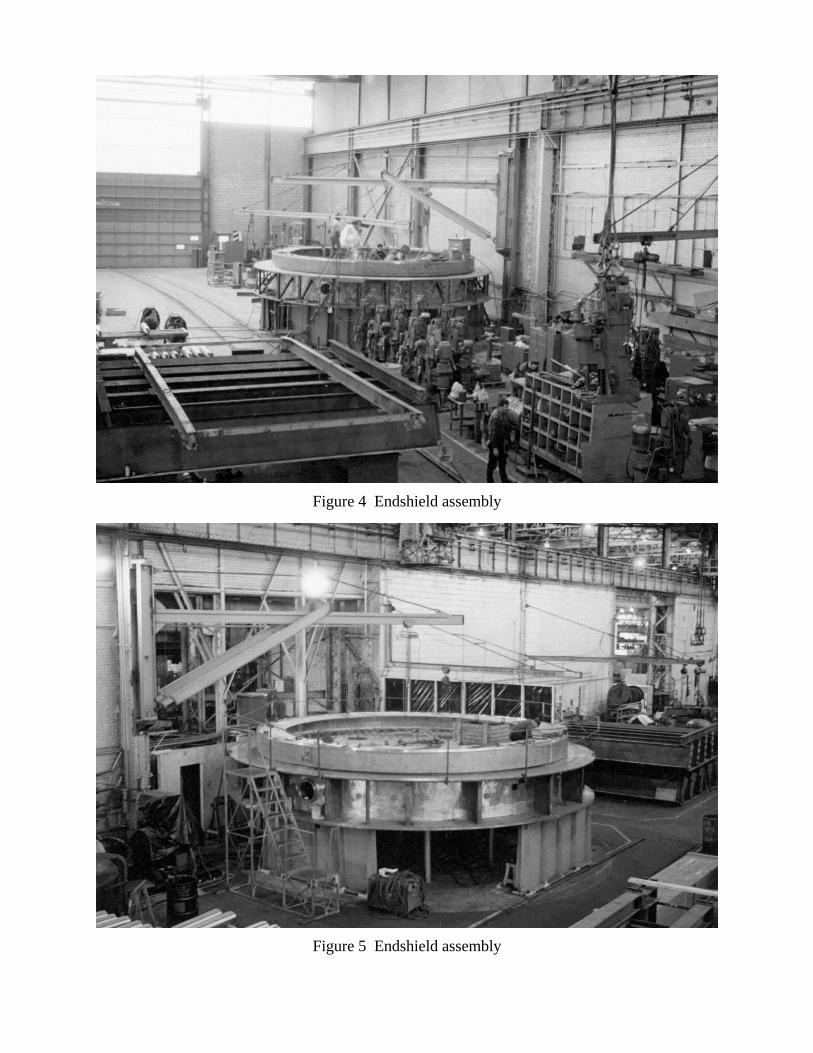
Figure 4 Endshield assembly
Figure 5 Endshield assembly
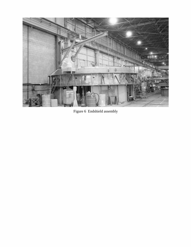
Figure 6 Endshield assembly
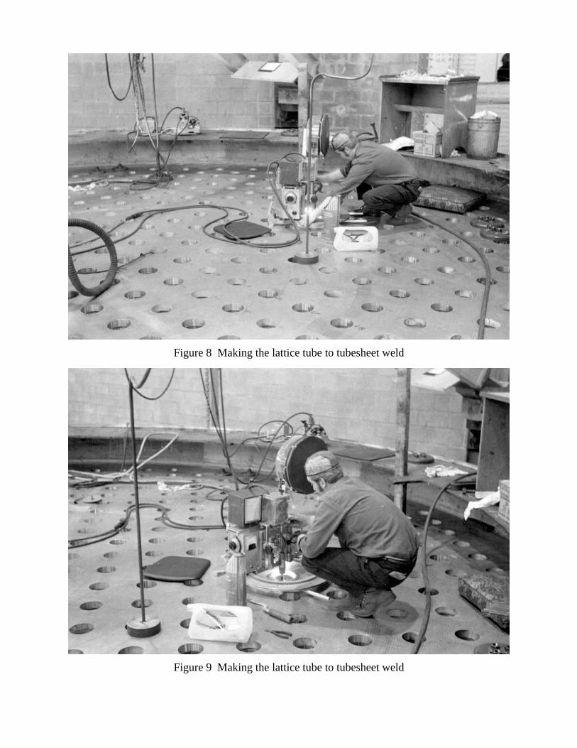
Figure 8 Making the lattice tube to tubesheet weld
Figure 9 Making the lattice tube to tubesheet weld
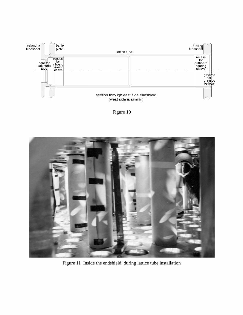
Figure 10
Figure 11 Inside the endshield, during lattice tube installation
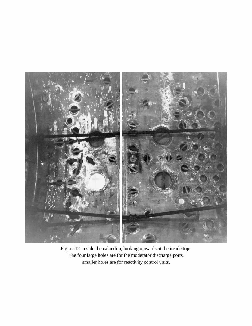
Figure 12 Inside the calandria, looking upwards at the inside top. The four large holes are for the moderator discharge ports,
smaller holes are for reactivity control units.
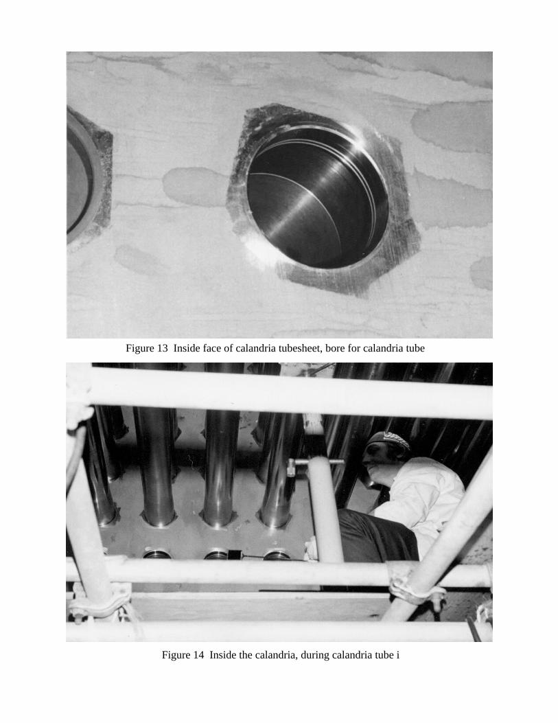
Figure 13 Inside face of calandria tubesheet, bore for calandria tube
Figure 14 Inside the calandria, during calandria tube i
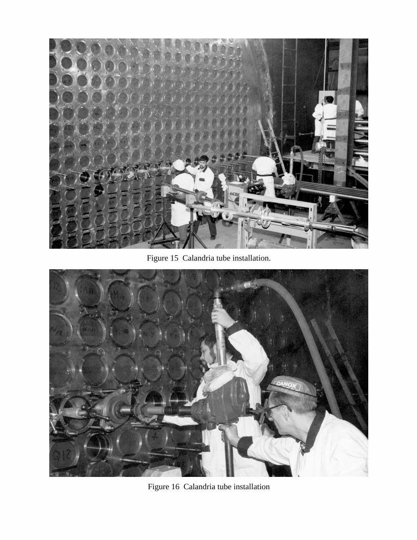
Figure 15 Calandria tube installation.
Figure 16 Calandria tube installation
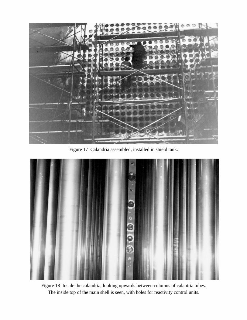
Figure 17 Calandria assembled, installed in shield tank.
Figure 18 Inside the calandria, looking upwards between columns of calantria tubes.The inside top of the main shell is seen, with holes for reactivity control units.
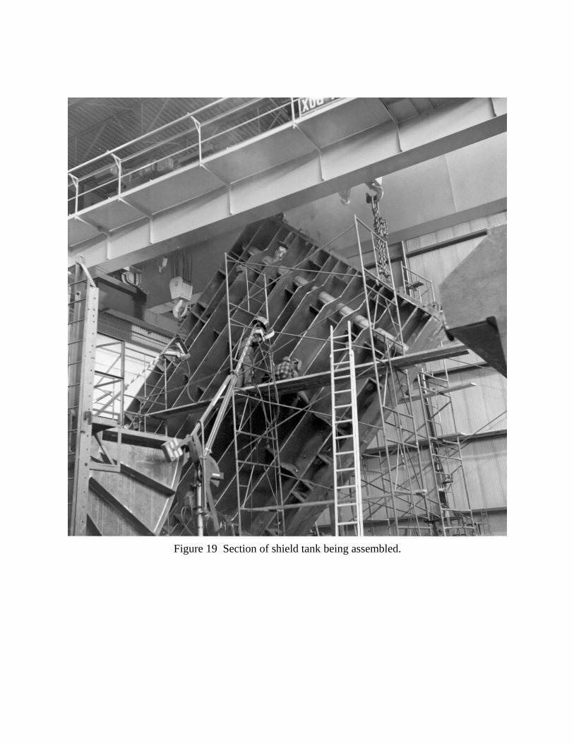
Figure 19 Section of shield tank being assembled.
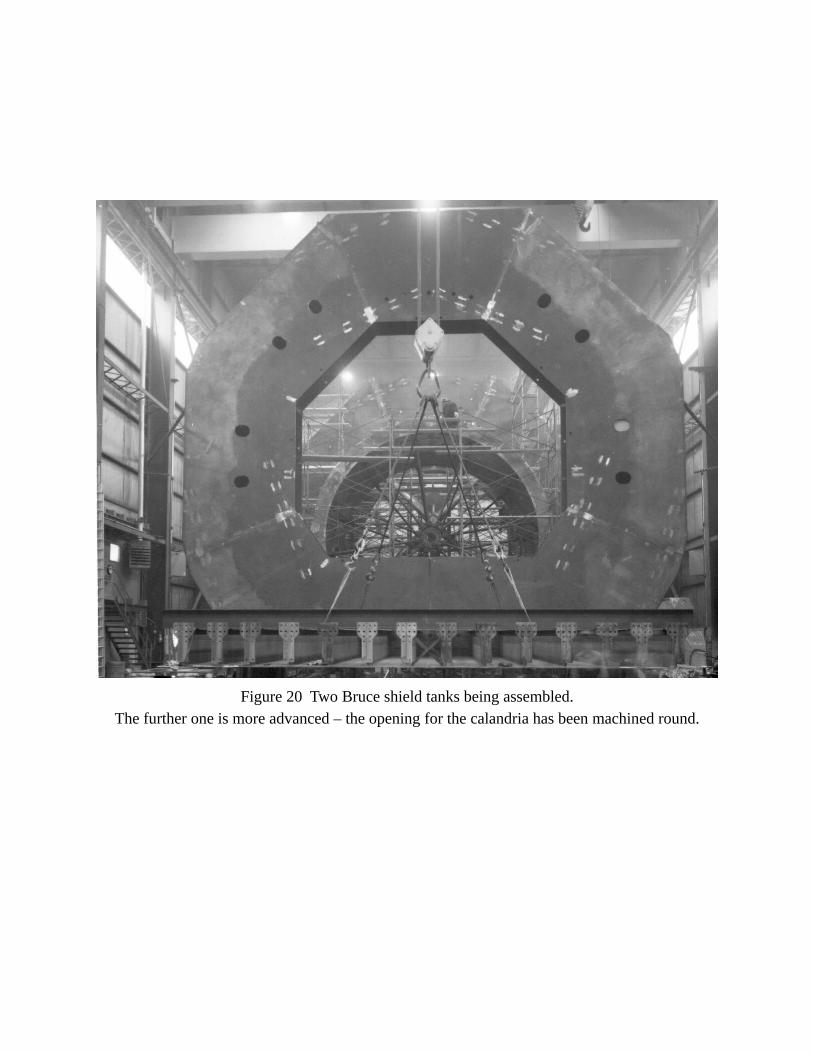
Figure 20 Two Bruce shield tanks being assembled.The further one is more advanced – the opening for the calandria has been machined round.
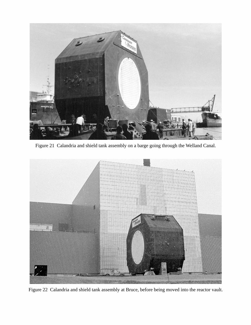
Figure 21 Calandria and shield tank assembly on a barge going through the Welland Canal.
Figure 22 Calandria and shield tank assembly at Bruce, before being moved into the reactor vault.