Embed Size (px)
Citation preview
TRANSMISSION LINE & SUBSTATION PROJECTS
COMPANY: ENTERGY GULF STATES LOUISIANA, L.L.C.
CUSTOMER: PID 244
FACILITIES STUDY
EJO NO. F4PPGS0477
PID 244 GENERATOR INTERCONNECTION
Revision: 1
Rev Issue Date
Description of Revision Prepared
By Approved
By
A 10/11/10 Initial Draft SRB BKW
B 2/1/11 Issue for Review SRB BKW
C 2/8/11 Issue to ICT SRB BKW
0 2/8/11 ICT Review and Upgrade Classification EC BR
1 2/28/11 Removal of “combine cycle” wording from Section 1.1 per customer request
EC BR

PID 244 Facilities Study
Page 2 of 23
TABLE OF CONTENTS
PROJECT SUMMARY ................................................................................. 4
1.1. Background and Project Need............................................................................... 4
1.2. Customer Facilities ................................................................................................ 4 1.3. Scope Summary .................................................................................................... 4
A. Scope for ERIS: ............................................................................................ 4
B. Scope for NRIS: ........................................................................................... 5
1.4. Impact of Priors ..................................................................................................... 5
1.5. Cost Summary ....................................................................................................... 5 A. For ERIS ....................................................................................................... 5
B. For NRIS ...................................................................................................... 5
1.6. Schedule Summary (Worst Case) ......................................................................... 5 1.7. Long Lead and Major Material / Equipment ........................................................... 5
SAFETY ....................................................................................................... 6
GENERAL ASSUMPTIONS ......................................................................... 6
SCOPE OF WORK ....................................................................................... 6
1.8. Interconnection Facilities [common to both ERIS & NRIS] .................................... 6 1.9. T-Line Task 1 ........................................................................................................ 6 1.10. T-Substation Task 1 .............................................................................................. 6
COST............................................................................................................ 6
UPGRADE CLASSIFICATION ..................................................................... 7
SCHEDULE .................................................................................................. 7
INTERCONNECTION STANDARDS ............................................................ 7
RISK ASSESSMENT.................................................................................... 7
CONFIRMED RESERVATIONS ................................................................... 7
ATTACHMENTS .......................................................................................... 9
A. Table of Acronyms ............................................................................................ 9
B. Scope Summary Diagram / Area Map .............................................................. 9
C. One Line Drawings ........................................................................................... 9
D. Electrical Arrangement ..................................................................................... 9
E. Duration Schedule ............................................................................................ 9
APPENDIX A: STABILITY ANALYSIS ...................................................... 10

PID 244 Facilities Study
Page 3 of 23
APPENDIX B: STABILITY MODEL OF BIG CAJUN #2 UNITS ................. 12
APPENDIX C: TRANSIENT STABILITY PLOTS ....................................... 15
PID 244 Facilities Study
Page 4 of 23
1. PROJECT SUMMARY
1.1. Background and Project Need
The purpose of this Facilities Study is to determine the availability to connect a new generation facility and provide the transfer capability at the point of interconnection. Also increased load flows, produced by making this interconnection, will be identified. This Facility Study will evaluate PID 244 request for interconnection of a 13 MW increase of generation for a total generator output of 588 MW. The customer has requested a 20% estimate. To evaluate this request, a study was performed on the latest available 2011 summer peak cases, using PSS/E and MUST software by Power Technologies Incorporated (PTI). The Facilities Study will identify the transmission interconnection requirements, any transmission constraints resulting from the requested power transfer, and any additional study also includes cost estimates to correct any transmission constraints. The customer has requested Energy Resource Interconnection Service (ERIS). No upgrades have been identified for ERIS.
1.2. Customer Facilities
The customer’s existing unit is a coal fired boiler with a GE steam-turbine generator. The unit is located in New Roads, LA.
1.3. Scope Summary
A. Scope for ERIS:
The ERIS was based on a request for interconnection on Entergy's transmission system located at the Big Cajun #2 500kV Substation. No network upgrades have been identified for ERIS.
A short circuit analysis was performed to determine if the proposed generation would cause the available fault current to surpass the fault duty of existing equipment within the Entergy transmission system. The analysis determined that additional generation proposed by PID 244 does not cause an increase in short circuit current such that it exceeds the fault interrupting capability of high voltage circuit breakers within the vicinity of PID 244.
A Stability Study was performed to evaluate the impact of PID 244 on the stability of the Entergy transmission system and nearby generating stations. The study concluded that no stability violations exist following simulated three-phase normally cleared faults and single phase stuck-

PID 244 Facilities Study
Page 5 of 23
breaker faults. Additionally, no voltage criteria violations were observed. A detailed description of the Stability Study analysis is described in Appendix A.
B. Scope for NRIS:
NRIS was not requested by the Customer.
1.4. Impact of Priors
PID 244 does not depend on other ongoing or planned Entergy Projects. As a result, the status of previously identified Entergy projects does not impact the cost or schedule of this interconnection.
1.5. Cost Summary
A. For ERIS
The estimated total project cost is $0. This cost does not include Tax Gross Up which may apply.
The ICT has assigned $0 as Base Plan upgrades and $0 as Supplemental Upgrades based on Attachment “T” of Entergy’s ICT (Independent Coordinator of Transmission) filing to the FERC.
B. For NRIS
NRIS was not requested by the Customer.
1.6. Schedule Summary (Worst Case)
The customer’s requested in service date is 4th quarter 2011. There are no network upgrades identified to accommodate this generation increase. Therefore, there is no summary of work for Entergy to perform.
WO Name Requested ISD Estimated ISD
N/A N/A N/A
1.7. Long Lead and Major Material / Equipment
Quantity Material Description
Lead Time (Weeks)
N/A N/A N/A

PID 244 Facilities Study
Page 6 of 23
2. SAFETY
Safety is a priority with Entergy. Safety will be designed into substations and lines. The designs will be done with the utmost safety for personnel in mind for construction, operation, and maintenance of the equipment. The National Electric Safety Code and the National Electrical Code will be used as the standards in the design & construction of the identified projects. Should the work contained within this Facility Study be approved, a detailed Safety Plan will be formulated and incorporated within the project plan.
3. GENERAL ASSUMPTIONS
N/A
4. SCOPE OF WORK
4.1. Interconnection Facilities [common to both ERIS & NRIS]
N/A 4.2. T-Line Task 1
N/A 4.3. T-Substation Task 1
N/A
5. COST
The ICT has reviewed and determined whether each required upgrade will be considered a Base Plan Upgrade or a Supplemental Upgrade. For more information on cost responsibility for Base Plan and Supplemental Upgrades, see Attachment T to Entergy’s OATT. The costs shown in the table include all applicable overheads but do not include tax gross up. Entergy incurs a tax liability proportional to the amount of customer contributions.
Estimated Task Costs
Task 2010 2011 2012
2013 Total
N/A N/A N/A
N/A N/A N/A
PID 244 Facilities Study
Page 7 of 23
6. UPGRADE CLASSIFICATION
The ICT has reviewed and determined whether each required upgrade will be considered a Supplemental Upgrade. For more information on cost responsibility for Base Plan and Supplemental Upgrades, see Attachment T to Entergy’s OATT.
7. SCHEDULE
No network upgrades have been identified for this request. Therefore, there is no schedule associated with any work required of Entergy to accommodate this request. It is assumed that the 13MW increase will take place in the 4th quarter of 2011 as per the customer’s Interconnection Request.
Task Name
Estimated Start Date
Estimated ISD/Completion
N/A N/A N/A
Notes to Duration Schedules:
N/A
8. INTERCONNECTION STANDARDS
http://entergy.com/transmission/facility_requirements.aspx
9. RISK ASSESSMENT
N/A
Risk Comment Impact
N/A
*-low impact to cost, ** - moderate impact to cost, ***- high impact to cost, **** - very high impact to cost.
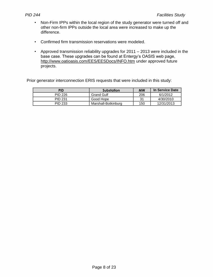
10. CONFIRMED RESERVATIONS
The following modifications were made to the base cases to reflect the latest information available:
Task Total Cost Base Plan Supplemental
Reference
N/A N/A N/A N/A N/A
PID 244 Facilities Study
Page 8 of 23
• Non-Firm IPPs within the local region of the study generator were turned off and other non-firm IPPs outside the local area were increased to make up the difference.
• Confirmed firm transmission reservations were modeled. • Approved transmission reliability upgrades for 2011 – 2013 were included in the
base case. These upgrades can be found at Entergy’s OASIS web page, http://www.oatioasis.com/EES/EESDocs/INFO.htm under approved future projects.
Prior generator interconnection ERIS requests that were included in this study:
PID Substation MW In Service Date
PID 226 Grand Gulf 206 6/1/2012
PID 231 Good Hope 31 4/30/2010
PID 233 Marshall-Botkinburg 150 12/31/2013

PID 244 Facilities Study
Page 9 of 23
11. ATTACHMENTS
A. Table of Acronyms
ACSR Aluminum Conductor Steel Reinforced
ACSS Aluminum Conductor Steel Supported
ADEQ Arkansas Department of Environmental Quality
AFUDC Allowance for Funds Used During Construction
ATC Available Transfer Capability
EES Entergy Control Area
EHV Extra-High Voltage
ERIS Energy Resource Interconnection Service
ICT Independent Coordinator of Transmission
kV Kilo-Volt
MCM (M) Thousand Circular Mils
MVA Mega-Volt Amp
MW Mega-Watt
NPDES National Pollution Discharge Elimination System
NOI Notice of Intent
NRIS Network Resource Interconnection Service
OASIS Online Access and Same-time Information System
OATT Open Access Transmission Tariff
POD Point of Delivery
POR Point of Receipt
SES Steam Electric Station
SOC System Operations Center
SHV Super High Voltage
SW Switch Station
TOC Transmission Operations Center
B. Scope Summary Diagram / Area Map
N/A
C. One Line Drawings
N/A
D. Electrical Arrangement
N/A
E. Duration Schedule
N/A
PID 244 Facilities Study
Page 10 of 23
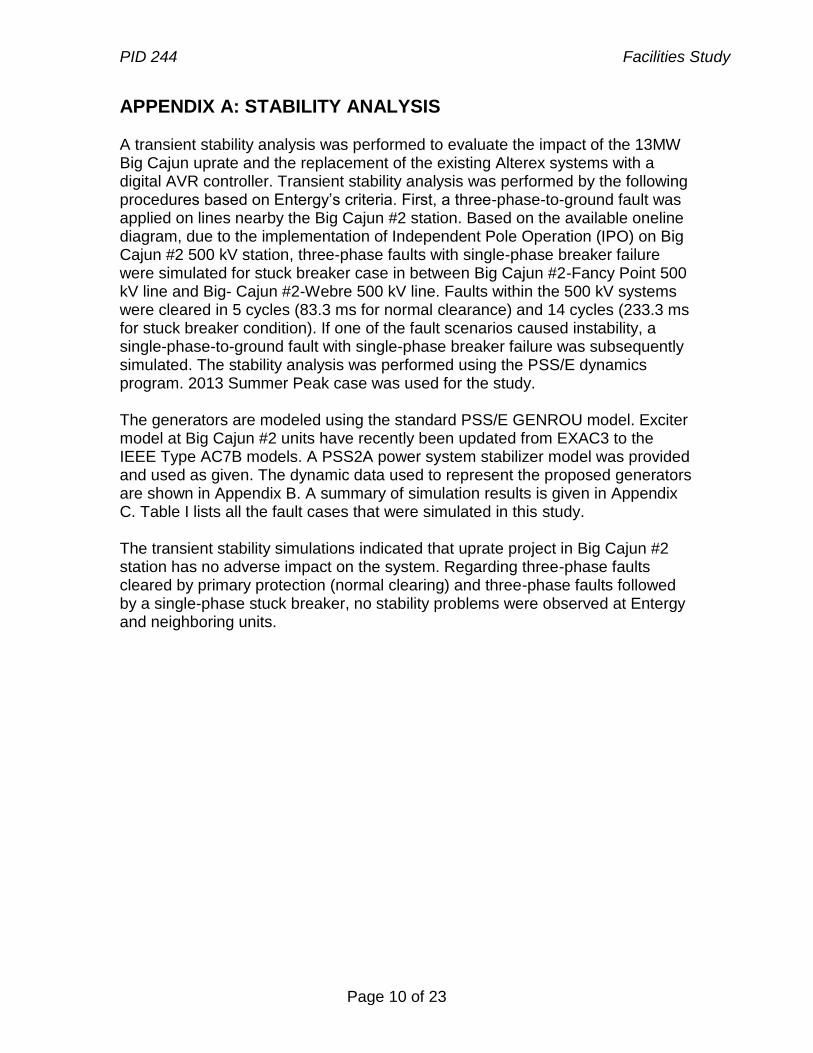
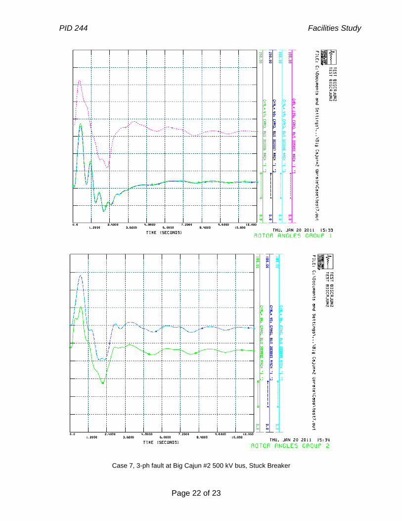
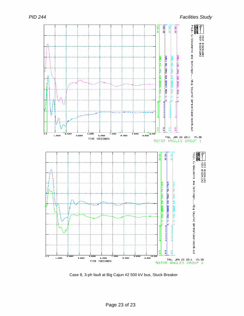
APPENDIX A: STABILITY ANALYSIS A transient stability analysis was performed to evaluate the impact of the 13MW Big Cajun uprate and the replacement of the existing Alterex systems with a digital AVR controller. Transient stability analysis was performed by the following procedures based on Entergy’s criteria. First, a three-phase-to-ground fault was applied on lines nearby the Big Cajun #2 station. Based on the available oneline diagram, due to the implementation of Independent Pole Operation (IPO) on Big Cajun #2 500 kV station, three-phase faults with single-phase breaker failure were simulated for stuck breaker case in between Big Cajun #2-Fancy Point 500 kV line and Big- Cajun #2-Webre 500 kV line. Faults within the 500 kV systems were cleared in 5 cycles (83.3 ms for normal clearance) and 14 cycles (233.3 ms for stuck breaker condition). If one of the fault scenarios caused instability, a single-phase-to-ground fault with single-phase breaker failure was subsequently simulated. The stability analysis was performed using the PSS/E dynamics program. 2013 Summer Peak case was used for the study. The generators are modeled using the standard PSS/E GENROU model. Exciter model at Big Cajun #2 units have recently been updated from EXAC3 to the IEEE Type AC7B models. A PSS2A power system stabilizer model was provided and used as given. The dynamic data used to represent the proposed generators are shown in Appendix B. A summary of simulation results is given in Appendix C. Table I lists all the fault cases that were simulated in this study. The transient stability simulations indicated that uprate project in Big Cajun #2 station has no adverse impact on the system. Regarding three-phase faults cleared by primary protection (normal clearing) and three-phase faults followed by a single-phase stuck breaker, no stability problems were observed at Entergy and neighboring units.
PID 244 Facilities Study
Page 11 of 23
Table I – Simulation Results for Normally-Cleared and Stuck-Breaker Faults
Fault
Case
#
Fault Location Fault
Type
Fault Clrng
Time (ms)
SLG Fault
Impedance
(Ohm)
Stuck Breaker#
Primary Breaker Trip # Secondary
Breaker Trip # Stable?
1 Big Cajun #2 500 kV 3PH 83.3 - - Big Cajun #2 Brk# 20550, 20555, Webre Brk# 20580, 20565
- Yes
2 Webre 500 kV 3PH 83.3 - - Big Cajun #2 Brk# 20550, 20555, Webre Brk# 20580, 20565
- Yes
3 Big Cajun #2 500 kV 3PH 83.3 - - Big Cajun #2 Brk# 20535, 20540, Fancy Point Brk# 20770, 20775
- Yes
4 Fancy Point 500 kV 3PH 83.3 - - Big Cajun #2 Brk# 20535, 20540, Fancy Point Brk# 20770, 20775
- Yes
5 Big Cajun #2 500 kV 3PH-SLG
233 1.414+j21.8 Brk #20550 Big Cajun #2 Brk# 20555, Webre Brk# 20580, 20565
Big Cajun #2 Brk# 20550
Yes
6 Big Cajun #2 500 kV 3PH-SLG
233 1.414+j21.8 Brk #20555 Big Cajun #2 Brk# 20550, Webre Brk# 20580, 20565
Big Cajun #2 Brk# 20555, 20560
Yes
7 Big Cajun #2 500 kV 3PH-SLG
233 1.783+j27.7 Brk #20535 Big Cajun #2 Brk# 20540, Fancy Point Brk# 20770, 20775
Big Cajun #2 Brk# 20535
Yes
8 Big Cajun #2 500 kV 3PH-SLG
233 1.783+j27.7 Brk #20540 Big Cajun #2 Brk# 20535, Fancy Point Brk# 20770, 20775
Big Cajun #2 Brk# 20540, 20545
Yes
PID 244 Facilities Study
Page 12 of 23
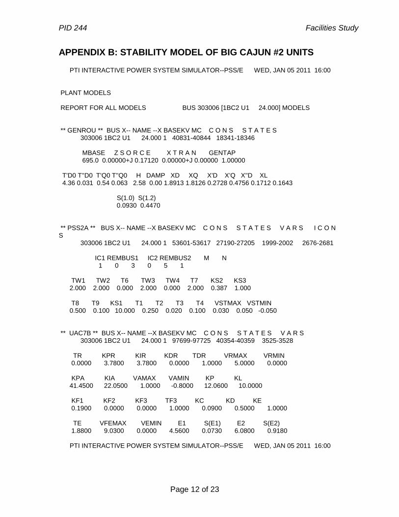
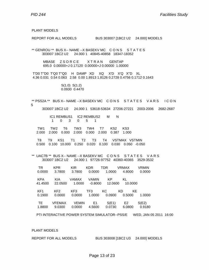
APPENDIX B: STABILITY MODEL OF BIG CAJUN #2 UNITS PTI INTERACTIVE POWER SYSTEM SIMULATOR--PSS/E WED, JAN 05 2011 16:00 PLANT MODELS REPORT FOR ALL MODELS BUS 303006 [1BC2 U1 24.000] MODELS ** GENROU ** BUS X-- NAME --X BASEKV MC C O N S S T A T E S 303006 1BC2 U1 24.000 1 40831-40844 18341-18346 MBASE Z S O R C E X T R A N GENTAP 695.0 0.00000+J 0.17120 0.00000+J 0.00000 1.00000 T'D0 T''D0 T'Q0 T''Q0 H DAMP XD XQ X'D X'Q X''D XL 4.36 0.031 0.54 0.063 2.58 0.00 1.8913 1.8126 0.2728 0.4756 0.1712 0.1643 S(1.0) S(1.2) 0.0930 0.4470 ** PSS2A ** BUS X-- NAME --X BASEKV MC C O N S S T A T E S V A R S I C O N S 303006 1BC2 U1 24.000 1 53601-53617 27190-27205 1999-2002 2676-2681 IC1 REMBUS1 IC2 REMBUS2 M N 1 0 3 0 5 1 TW1 TW2 T6 TW3 TW4 T7 KS2 KS3 2.000 2.000 0.000 2.000 0.000 2.000 0.387 1.000 T8 T9 KS1 T1 T2 T3 T4 VSTMAX VSTMIN 0.500 0.100 10.000 0.250 0.020 0.100 0.030 0.050 -0.050 ** UAC7B ** BUS X-- NAME --X BASEKV MC C O N S S T A T E S V A R S 303006 1BC2 U1 24.000 1 97699-97725 40354-40359 3525-3528 TR KPR KIR KDR TDR VRMAX VRMIN 0.0000 3.7800 3.7800 0.0000 1.0000 5.0000 0.0000 KPA KIA VAMAX VAMIN KP KL 41.4500 22.0500 1.0000 -0.8000 12.0600 10.0000 KF1 KF2 KF3 TF3 KC KD KE 0.1900 0.0000 0.0000 1.0000 0.0900 0.5000 1.0000 TE VFEMAX VEMIN E1 S(E1) E2 S(E2) 1.8800 9.0300 0.0000 4.5600 0.0730 6.0800 0.9180 PTI INTERACTIVE POWER SYSTEM SIMULATOR--PSS/E WED, JAN 05 2011 16:00
PID 244 Facilities Study
Page 13 of 23
PLANT MODELS REPORT FOR ALL MODELS BUS 303007 [1BC2 U2 24.000] MODELS ** GENROU ** BUS X-- NAME --X BASEKV MC C O N S S T A T E S 303007 1BC2 U2 24.000 1 40845-40858 18347-18352 MBASE Z S O R C E X T R A N GENTAP 695.0 0.00000+J 0.17120 0.00000+J 0.00000 1.00000 T'D0 T''D0 T'Q0 T''Q0 H DAMP XD XQ X'D X'Q X''D XL 4.36 0.031 0.54 0.063 2.58 0.00 1.8913 1.8126 0.2728 0.4756 0.1712 0.1643 S(1.0) S(1.2) 0.0930 0.4470 ** PSS2A ** BUS X-- NAME --X BASEKV MC C O N S S T A T E S V A R S I C O N S 303007 1BC2 U2 24.000 1 53618-53634 27206-27221 2003-2006 2682-2687 IC1 REMBUS1 IC2 REMBUS2 M N 1 0 3 0 5 1 TW1 TW2 T6 TW3 TW4 T7 KS2 KS3 2.000 2.000 0.000 2.000 0.000 2.000 0.387 1.000 T8 T9 KS1 T1 T2 T3 T4 VSTMAX VSTMIN 0.500 0.100 10.000 0.250 0.020 0.100 0.030 0.050 -0.050 ** UAC7B ** BUS X-- NAME --X BASEKV MC C O N S S T A T E S V A R S 303007 1BC2 U2 24.000 1 97726-97752 40360-40365 3529-3532 TR KPR KIR KDR TDR VRMAX VRMIN 0.0000 3.7800 3.7800 0.0000 1.0000 4.8000 0.0000 KPA KIA VAMAX VAMIN KP KL 41.4500 22.0500 1.0000 -0.8000 12.0600 10.0000 KF1 KF2 KF3 TF3 KC KD KE 0.1900 0.0000 0.0000 1.0000 0.0900 0.5000 1.0000 TE VFEMAX VEMIN E1 S(E1) E2 S(E2) 1.8800 9.0300 0.0000 4.5600 0.0730 6.0800 0.9180 PTI INTERACTIVE POWER SYSTEM SIMULATOR--PSS/E WED, JAN 05 2011 16:00 PLANT MODELS REPORT FOR ALL MODELS BUS 303008 [1BC2 U3 24.000] MODELS

PID 244 Facilities Study
Page 14 of 23
** GENROU ** BUS X-- NAME --X BASEKV MC C O N S S T A T E S 303008 1BC2 U3 24.000 1 40859-40872 18353-18358 MBASE Z S O R C E X T R A N GENTAP 688.0 0.00000+J 0.17120 0.00000+J 0.00000 1.00000 T'D0 T''D0 T'Q0 T''Q0 H DAMP XD XQ X'D X'Q X''D XL 4.36 0.031 0.54 0.063 2.58 0.00 1.8913 1.8126 0.2728 0.4756 0.1712 0.1643 S(1.0) S(1.2) 0.0930 0.4470 ** PSS2A ** BUS X-- NAME --X BASEKV MC C O N S S T A T E S V A R S I C O N S 303008 1BC2 U3 24.000 1 53635-53651 27222-27237 2007-2010 2688-2693 IC1 REMBUS1 IC2 REMBUS2 M N 1 0 3 0 5 1 TW1 TW2 T6 TW3 TW4 T7 KS2 KS3 2.000 2.000 0.000 2.000 0.000 2.000 0.387 1.000 T8 T9 KS1 T1 T2 T3 T4 VSTMAX VSTMIN 0.500 0.100 10.000 0.250 0.020 0.100 0.030 0.050 -0.050 ** UAC7B ** BUS X-- NAME --X BASEKV MC C O N S S T A T E S V A R S 303008 1BC2 U3 24.000 1 97753-97779 40366-40371 3533-3536 TR KPR KIR KDR TDR VRMAX VRMIN 0.0000 3.7800 3.7800 0.0000 1.0000 4.7200 0.0000 KPA KIA VAMAX VAMIN KP KL 41.4500 22.0500 1.0000 -0.8000 12.0600 10.0000 KF1 KF2 KF3 TF3 KC KD KE 0.1900 0.0000 0.0000 1.0000 0.0900 0.5000 1.0000 TE VFEMAX VEMIN E1 S(E1) E2 S(E2) 1.8800 9.0300 0.0000 4.5600 0.0730 6.0800 0.9180
PID 244 Facilities Study
Page 15 of 23
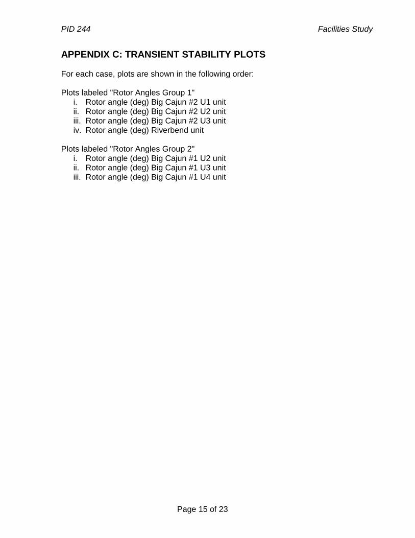
APPENDIX C: TRANSIENT STABILITY PLOTS
For each case, plots are shown in the following order: Plots labeled "Rotor Angles Group 1"
i. Rotor angle (deg) Big Cajun #2 U1 unit ii. Rotor angle (deg) Big Cajun #2 U2 unit iii. Rotor angle (deg) Big Cajun #2 U3 unit iv. Rotor angle (deg) Riverbend unit
Plots labeled "Rotor Angles Group 2"
i. Rotor angle (deg) Big Cajun #1 U2 unit ii. Rotor angle (deg) Big Cajun #1 U3 unit iii. Rotor angle (deg) Big Cajun #1 U4 unit

PID 244 Facilities Study
Page 16 of 23
Case 1, 3-ph fault at Big Cajun #2 500 kV bus, Primary Clearing

PID 244 Facilities Study
Page 17 of 23
Case 2, 3-ph fault at Webre 500 kV bus, Primary Clearing
PID 244 Facilities Study
Page 18 of 23
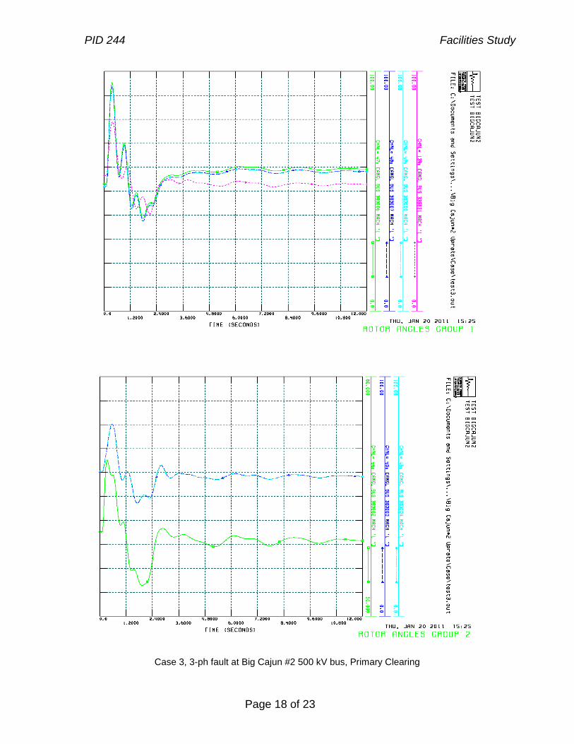
Case 3, 3-ph fault at Big Cajun #2 500 kV bus, Primary Clearing

PID 244 Facilities Study
Page 19 of 23
Case 4, 3-ph fault at Fancy Point 500 kV bus, Primary Clearing

PID 244 Facilities Study
Page 20 of 23
Case 5, 3-ph fault at Big Cajun #2 500 kV bus, Stuck Breaker
PID 244 Facilities Study
Page 21 of 23
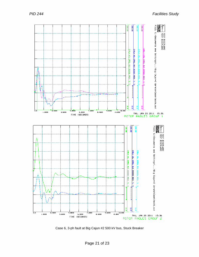
Case 6, 3-ph fault at Big Cajun #2 500 kV bus, Stuck Breaker
PID 244 Facilities Study
Page 22 of 23
Case 7, 3-ph fault at Big Cajun #2 500 kV bus, Stuck Breaker
PID 244 Facilities Study
Page 23 of 23
Case 8, 3-ph fault at Big Cajun #2 500 kV bus, Stuck Breaker


![A New Method for Diagnostics of Faults of Three-phase ... · faults in squirrel-cage asynchronous motors [14]. Considering the literature, we noticed that acoustic signals could be](https://img.pdfslide.net/doc/110x75/60779df7a537a45b3b247fc6/a-new-method-for-diagnostics-of-faults-of-three-phase-faults-in-squirrel-cage.jpg)