Embed Size (px)
Citation preview

Preface, Contents
Product Overview � Modular PID Control
1
Description of the Functions2
Examples3
Technical Data4
Configuration Tool for Modular PID Control
5
Appendices
References A
Index
Edition 11/2003A5E00275589-01
Modular PID Control
Manual
SIMATIC

!Danger
indicates that death, severe personal injury or substantial property damage will result if proper precautionsare not taken.
!Warning
indicates that death, severe personal injury or substantial property damage can result if properprecautions are not taken.
!Caution
indicates that minor personal injury can result if proper precautions are not taken.
Caution
indicates that property damage can result if proper precautions are not taken.
Notice
draws your attention to particularly important information on the product, handling the product, or to aparticular part of the documentation.
Qualified PersonnelOnly qualified personnel should be allowed to install and work on this equipment. Qualified persons aredefined as persons who are authorized to commission, to ground and to tag circuits, equipment, andsystems in accordance with established safety practices and standards.
Correct UsageNote the following:
!Warning
This device and its components may only be used for the applications described in the catalog or thetechnical description, and only in connection with devices or components from other manufacturers whichhave been approved or recommended by Siemens.
This product can only function correctly and safely if it is transported, stored, set up, and installedcorrectly, and operated and maintained as recommended.
TrademarksSIMATIC, SIMATIC HMI and SIMATIC NET are registered trademarks of SIEMENS AG.
Third parties using for their own purposes any other names in this document which refer to trademarksmight infringe upon the rights of the trademark owners.
Safety GuidelinesThis manual contains notices intended to ensure personal safety, as well as to protect the products andconnected equipment against damage. These notices are highlighted by the symbols shown below andgraded according to severity by the following texts:
We have checked the contents of this manual for agreementwith the hardware and software described. Since deviationscannot be precluded entirely, we cannot guarantee fullagreement. However, the data in this manual are reviewedregularly and any necessary corrections included insubsequent editions. Suggestions for improvement arewelcomed.
Disclaim of LiabilityCopyright � Siemens AG 2003 All rights reserved
The reproduction, transmission or use of this document or itscontents is not permitted without express written authority.Offenders will be liable for damages. All rights, including rightscreated by patent grant or registration of a utility model ordesign, are reserved.
Siemens AGBereich Automation and DrivesGeschaeftsgebiet Industrial Automation SystemsPostfach 4848, D- 90327 Nuernberg
Siemens AG 2003Technical data subject to change.
Siemens Aktiengesellschaft A5E00262404-01
iiiModular PID ControlA5E00275589-01
Preface
Purpose of the Manual
This manual will help you when selecting, configuring, and assigning parameters toa controller block for your control task.
The manual introduces you to the functions of the controller block and explainshow to use the Startup and Configuration tool.
Required Basic Knowledge
To understand this manual, you should be familiar with automation and processcontrol engineering.
In addition, you should know how to use computers or devices with similarfunctions (e.g programming devices) under Windows operating systems. Sincemodular PID Control is based on the STEP 7 software, you should also know howto operate it. This is provided in the manual �Programming with STEP 7 V5.1�.
Where is this Manual valid?
This manual is valid for the software packages Modular PID Control V5.0 andModular PID Control Tool V5.0.
Preface
ivModular PID Control
A5E00275589-01
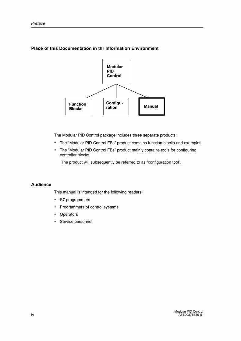
Place of this Documentation in thr Information Environment
Modular PIDControl
FunctionBlocks
Configu-ration Manual
The Modular PID Control package includes three separate products:
• The �Modular PID Control FBs� product contains function blocks and examples.
• The �Modular PID Control FBs� product mainly contains tools for configuringcontroller blocks.
The product will subsequently be referred to as �configuration tool�.
Audience
This manual is intended for the following readers:
• S7 programmers
• Programmers of control systems
• Operators
• Service personnel
Preface
vModular PID ControlA5E00275589-01
Conventions in the Text
To make it easier for you to find information in the manual, certain conventionshave been used:
• First glance through the titles in the left margin to get an idea of the content of asection.
• Sections dealing with a specific topic either answer a question about thefunctions of the tool or provide information about necessary or recommendedcourses of action.
• References to further information dealing with a topic are indicated by (seeChapter or Section x.y). References to other documentation are indicated by anumber in slashes /.../. Based on these numbers, you can refer to theReferences in the Appendix if you require the full title of the documentation.
• You will find a glossary with important controller terms in the manual �StandardPID Control�
Further Support
If you have any technical questions, please get in touch with your Siemensrepresentative or agent responsible.
You will find your contact person at:
http://www.siemens.com/automation/partner
Training Centers
Siemens offers a number of training courses to familiarize you with the SIMATICS7 automation system. Please contact your regional training center or our centraltraining center in D 90327 Nuremberg, Germany for details:
Telephone: +49 (911) 895-3200.
Internet: http://www.sitrain.com
Preface
viModular PID Control
A5E00275589-01
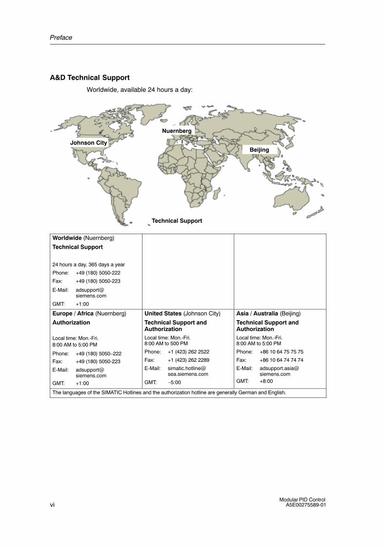
A&D Technical Support
Worldwide, available 24 hours a day:
Johnson City
Nuernberg
Beijing
Technical Support
Worldwide (Nuernberg)
Technical Support
24 hours a day, 365 days a year
Phone: +49 (180) 5050-222
Fax: +49 (180) 5050-223
E-Mail: [email protected]
GMT: +1:00
Europe / Africa (Nuernberg)
Authorization
Local time: Mon.-Fri. 8:00 AM to 5:00 PM
Phone: +49 (180) 5050�222
Fax: +49 (180) 5050-223
E-Mail: [email protected]
GMT: +1:00
United States (Johnson City)
Technical Support andAuthorizationLocal time: Mon.-Fri. 8:00 AM to 500 PM
Phone: +1 (423) 262 2522
Fax: +1 (423) 262 2289
E-Mail: [email protected]
GMT: �5:00
Asia / Australia (Beijing)
Technical Support andAuthorizationLocal time: Mon.-Fri. 8:00 AM to 5:00 PM
Phone: +86 10 64 75 75 75
Fax: +86 10 64 74 74 74
E-Mail: [email protected]
GMT: +8:00
The languages of the SIMATIC Hotlines and the authorization hotline are generally German and English.
Preface
viiModular PID ControlA5E00275589-01
Service & Support on the Internet
In addition to our documentation, we offer our Know-how online on the internet at:
http://www.siemens.com/automation/service&support
where you will find the following:
• The newsletter, which constantly provides you with up�to�date information onyour products.
• The right documents via our Search function in Service & Support.
• A forum, where users and experts from all over the world exchange theirexperiences.
• Your local representative for Automation & Drives.
• Information on field service, repairs, spare parts and more under �Services�.

Preface
viiiModular PID Control
A5E00275589-01
ixModular PID ControlA5E00275589-01
Contents
Preface iii. . . . . . . . . . . . . . . . . . . . . . . . . . . . . . . . . . . . . . . . . . . . . . . . . . . . . . . . . . . . . . . .
1 Product Overview � Modular PID Control 1-1. . . . . . . . . . . . . . . . . . . . . . . . . . . . . . . . .
1.1 The Product Modular PID Control 1-1. . . . . . . . . . . . . . . . . . . . . . . . . . . . . . . . . .
1.2 The Components of Modular PID Control 1-2. . . . . . . . . . . . . . . . . . . . . . . . . . .
1.3 Environment and Applications 1-3. . . . . . . . . . . . . . . . . . . . . . . . . . . . . . . . . . . . .
2 Description of the Functions 2-1. . . . . . . . . . . . . . . . . . . . . . . . . . . . . . . . . . . . . . . . . . . . 2.1 General Information 2-1. . . . . . . . . . . . . . . . . . . . . . . . . . . . . . . . . . . . . . . . . . . . . 2.1.1 A_DEAD_B: Adaptive Dead Band 2-2. . . . . . . . . . . . . . . . . . . . . . . . . . . . . . . . . 2.1.2 CRP_IN: Change Range Peripheral Input 2-8. . . . . . . . . . . . . . . . . . . . . . . . . . . 2.1.3 CRP_OUT: Change Range Peripheral Output 2-10. . . . . . . . . . . . . . . . . . . . . . . 2.1.4 DEAD_T: Dead Time 2-12. . . . . . . . . . . . . . . . . . . . . . . . . . . . . . . . . . . . . . . . . . . . . 2.1.5 DEADBAND: Dead Band 2-16. . . . . . . . . . . . . . . . . . . . . . . . . . . . . . . . . . . . . . . . . 2.1.6 DIF: Differentiator 2-19. . . . . . . . . . . . . . . . . . . . . . . . . . . . . . . . . . . . . . . . . . . . . . . 2.1.7 ERR_MON: Error Signal Monitoring 2-23. . . . . . . . . . . . . . . . . . . . . . . . . . . . . . . . 2.1.8 INTEG: Integrator 2-27. . . . . . . . . . . . . . . . . . . . . . . . . . . . . . . . . . . . . . . . . . . . . . . 2.1.9 LAG1ST: First-Order Lag Element 2-33. . . . . . . . . . . . . . . . . . . . . . . . . . . . . . . . . 2.1.10 LAG2ND: Second-Order Lag Element 2-37. . . . . . . . . . . . . . . . . . . . . . . . . . . . . . 2.1.11 LIMALARM: Limit Alarm 2-41. . . . . . . . . . . . . . . . . . . . . . . . . . . . . . . . . . . . . . . . . . 2.1.12 LIMITER: Limiter 2-45. . . . . . . . . . . . . . . . . . . . . . . . . . . . . . . . . . . . . . . . . . . . . . . . 2.1.13 LMNGEN_C: Output Continuous PID Controller 2-48. . . . . . . . . . . . . . . . . . . . . 2.1.14 LMNGEN_S: Output PID Step Controller 2-54. . . . . . . . . . . . . . . . . . . . . . . . . . . 2.1.15 LP_SCHED: Loop Scheduler 2-63. . . . . . . . . . . . . . . . . . . . . . . . . . . . . . . . . . . . . 2.1.16 NONLIN: Non-Linear Static Function 2-70. . . . . . . . . . . . . . . . . . . . . . . . . . . . . . . 2.1.17 NORM: Physical Normalization 2-75. . . . . . . . . . . . . . . . . . . . . . . . . . . . . . . . . . . . 2.1.18 OVERRIDE: Override Control 2-77. . . . . . . . . . . . . . . . . . . . . . . . . . . . . . . . . . . . . 2.1.19 PARA_CTL: Parameter Control 2-80. . . . . . . . . . . . . . . . . . . . . . . . . . . . . . . . . . . 2.1.20 PID: PID Algorithm 2-84. . . . . . . . . . . . . . . . . . . . . . . . . . . . . . . . . . . . . . . . . . . . . . 2.1.21 PULSEGEN: Pulse Generator 2-94. . . . . . . . . . . . . . . . . . . . . . . . . . . . . . . . . . . . 2.1.22 RMP_SOAK: Ramp Soak 2-104. . . . . . . . . . . . . . . . . . . . . . . . . . . . . . . . . . . . . . . . 2.1.23 ROC_LIM: Rate of Change Limiter 2-114. . . . . . . . . . . . . . . . . . . . . . . . . . . . . . . . . 2.1.24 SCALE: Linear Scaling 2-123. . . . . . . . . . . . . . . . . . . . . . . . . . . . . . . . . . . . . . . . . . . 2.1.25 SP_GEN: Setpoint Value Generator 2-125. . . . . . . . . . . . . . . . . . . . . . . . . . . . . . . 2.1.26 SPLT_RAN: Split Ranging 2-129. . . . . . . . . . . . . . . . . . . . . . . . . . . . . . . . . . . . . . . . 2.1.27 SWITCH: Switch 2-133. . . . . . . . . . . . . . . . . . . . . . . . . . . . . . . . . . . . . . . . . . . . . . . .

Contents
xModular PID Control
A5E00275589-01
3 Examples 3-1. . . . . . . . . . . . . . . . . . . . . . . . . . . . . . . . . . . . . . . . . . . . . . . . . . . . . . . . . . . . . .
3.1 Using Modular PID Control 3-1. . . . . . . . . . . . . . . . . . . . . . . . . . . . . . . . . . . . . . .
3.2 Example 1: Fixed Setpoint Controller with Switching Output for Integrating Actuators with Process Simulation 3-4. . . . . . . . . . . . . . . . . . . .
3.2.1 PIDCTR_S: Fixed Setpoint Controller with Switching Output for Integrating Actuators 3-6. . . . . . . . . . . . . . . . . . . . . . . . . . . . . . . . . . . . . . . . . .
3.2.2 PROC_S: Process for Step Controllers 3-8. . . . . . . . . . . . . . . . . . . . . . . . . . . . .
3.3 Example 2: Fixed Setpoint Controller with Continuous Output with Process Simulation 3-9. . . . . . . . . . . . . . . . . . . . . . . . . . . . . . . . . . . . . . . . . .
3.3.1 PIDCTR_C: Fixed Setpoint Controller with Continuous Output for Integrating Actuators 3-10. . . . . . . . . . . . . . . . . . . . . . . . . . . . . . . . . . . . . . . . . .
3.3.2 PROC_C: Process for Continuous Controller 3-11. . . . . . . . . . . . . . . . . . . . . . . .
3.4 Example 3: Fixed Setpoint Controller with Switching Output for Proportional Actuators with Process Simulation 3-12. . . . . . . . . . . . . . . . . . .
3.4.1 PIDCTR: Primary Controller for a Continuous Controller with Pulse Generator 3-14. . . . . . . . . . . . . . . . . . . . . . . . . . . . . . . . . . . . . . . . . . . .
3.4.2 PROC_P: Process for a Continuous Controller with Pulse Generator 3-15. . .
3.5 Example 4: Single-Loop Ratio Controller (RATIOCTR) 3-16. . . . . . . . . . . . . . . .
3.6 Example 5: Multiple-Loop Ratio Controller 3-18. . . . . . . . . . . . . . . . . . . . . . . . . .
3.7 Example 6: Blending Controller 3-22. . . . . . . . . . . . . . . . . . . . . . . . . . . . . . . . . . . .
3.8 Example 7: Cascade Controller 3-25. . . . . . . . . . . . . . . . . . . . . . . . . . . . . . . . . . .
3.9 Example 8: Controller with Precontroller (CTRC_PRE) 3-27. . . . . . . . . . . . . . .
3.10 Example 9: Controller with Feedforward Control (CTR_C_FF) 3-29. . . . . . . . .
3.11 Example 10: Range Splitting Controller (SPLITCTR) 3-31. . . . . . . . . . . . . . . . .
3.12 Example 11: Override Controller (OVR_CTR) 3-34. . . . . . . . . . . . . . . . . . . . . . .
3.13 Example 12: Multiple Variable Controller 3-37. . . . . . . . . . . . . . . . . . . . . . . . . . . .
4 Technical Data 4-1. . . . . . . . . . . . . . . . . . . . . . . . . . . . . . . . . . . . . . . . . . . . . . . . . . . . . . . . .
4.1 Run Times 4-1. . . . . . . . . . . . . . . . . . . . . . . . . . . . . . . . . . . . . . . . . . . . . . . . . . . . .
4.2 Work Memory Requirements 4-2. . . . . . . . . . . . . . . . . . . . . . . . . . . . . . . . . . . . . .
4.3 Rules of Thumb 4-3. . . . . . . . . . . . . . . . . . . . . . . . . . . . . . . . . . . . . . . . . . . . . . . . .
5 Configuration Tool for Modular PID Control 5-1. . . . . . . . . . . . . . . . . . . . . . . . . . . . . .
A References A-1. . . . . . . . . . . . . . . . . . . . . . . . . . . . . . . . . . . . . . . . . . . . . . . . . . . . . . . . . . . . .
Index Index-1. . . . . . . . . . . . . . . . . . . . . . . . . . . . . . . . . . . . . . . . . . . . . . . . . . . . . . . . . . . . .
1-1Modular PID ControlA5E00275589-01
Product Overview � Modular PID Control
1.1 The Product Modular PID Control
Concept of Modular PID Control
The �Modular PID Control� software product consists of a set of function blocks(FBs) and functions (FCs) containing the algorithms for creating controllerfunctions. This is therefore purely a software controller in which you can implementthe controller functions by interconnecting the blocks.
The block library is supplemented by a number of ready-to-use controllerstructures (single-loop fixed setpoint controller, ratio controller etc.) in the form ofexamples. You can copy and adapt these examples to suit your own control task.
When operating a large number of control loops, it is usually the case that someloops must be processed more often than others although each loop itself must beprocessed at equidistant intervals. For this situation, there is a loop scheduler(LP_SCHED) available with which extensive control systems can be configuredclearly and simply. This also ensures that the load on the CPU is spread out.
To help you install and test individual control loops, the package also includes theconfiguration tool �Modular PID Control Tool�. This includes a loop monitor, a curverecorder for manipulating and monitoring process variables, and an algorithm forprocess identification and optimization of the PID parameters.
Overview of the Basic Functions
In many control tasks, the classic PID controller that influences the process is notthe sole important element but great demands are also made on signal processing.
A controller created with the �Modular PID Control� software package thereforeconsists of a series of subfunctions for which you can select parameter valuesseparately. In addition to the actual controller with the PID algorithm, functions arealso available for processing the setpoint and process variable and for adapting thecalculated manipulated variable.
1
Product Overview � Modular PID Control
1-2Modular PID Control
A5E00275589-01
1.2 The Components of Modular PID Control
Modular PID Control FB
The �Modular PID Control FB� package consists of a library with function blocksand 12 ready-to-use examples of controllers.
You can install the software on programming devices/PCs with the SETUPprogram. The online help system provides you with information about subfunctionsand individual parameters while you are working.
Modular PID Control Tool
Using the �Startup and Test� tool, you can install, start up and test your controllerstructure and optimize the PID parameters.
The configuration tool includes a loop monitor, a curve recorder and an algorithmfor setting or optimizing the PID controller parameters. The configuration tool isdescribed in detail in Chapter 5.
Modular PID Control Manual
For details of the content of this manual, refer to the table of contents.
Product Overview � Modular PID Control
1-3Modular PID ControlA5E00275589-01
1.3 Environment and Applications
Hardware Environment
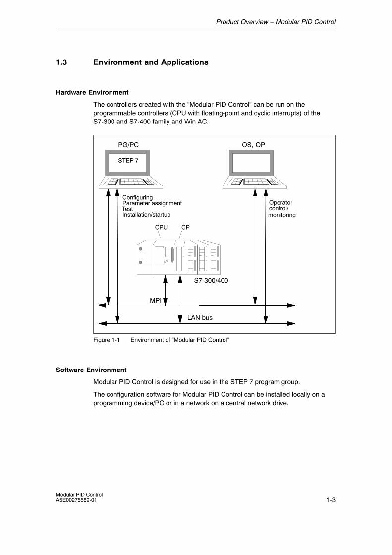
The controllers created with the �Modular PID Control� can be run on theprogrammable controllers (CPU with floating-point and cyclic interrupts) of theS7-300 and S7-400 family and Win AC.
PG/PC OS, OP
CPU
LAN bus
CP
S7-300/400
MPI
Operatorcontrol/
ConfiguringParameter assignmentTestInstallation/startup
STEP 7
monitoring
Figure 1-1 Environment of �Modular PID Control�
Software Environment
Modular PID Control is designed for use in the STEP 7 program group.
The configuration software for Modular PID Control can be installed locally on aprogramming device/PC or in a network on a central network drive.
Product Overview � Modular PID Control
1-4Modular PID Control
A5E00275589-01
Range of Functions of Modular PID Control
Both slow processes (temperatures, tank levels) and very fast processes (flowrate, motor speed) can be controlled. The following controller types can beimplemented:
• Continuous PID controllers
• PID step controllers for integrating actuators
• Pulse-break controllers
They can be connected to create one of the following controller structures:
• Fixed setpoint controllers
• Cascade controllers
• Ratio controllers
• Blending controllers
• Split range controllers
• Override controllers
• Controllers with feedforward control
• Multiple variable controllers
2-1Modular PID ControlA5E00275589-01
Description of the Functions
2.1 General Information
Conventions Used with Parameter and Block Names in the Block Diagrams
The names of the parameters are a maximum of 8 characters long.
The following conventions were used to name the parameters:
First letter:
Q general output of the type BOOL (Boolean variable)
SP setpoint
PV process variable
LMN manipulated variable or analog output signal
DISV disturbance variable
Following letters:
MAN manual value
INT internal
EXT external
_ON BOOLEAN variable to activate a function
Call Data
Most blocks in the Modular PID Control package require loop-specific call datasuch as the complete restart bit and sampling time. These values are transferredvia the inputs COM_RST and CYCLE.
Notes on the block parameters (input, output and in/out parameters)
• Default: these are the default values used when an instance is created.
• Permitted Values: the values set for the input parameters should not exceedthe permitted range of values. The range is not checked when the block isexecuted. The entry �technical range of values� means a physical variable witha value between approximately �10 6.
2
Description of the Functions
2-2Modular PID Control
A5E00275589-01
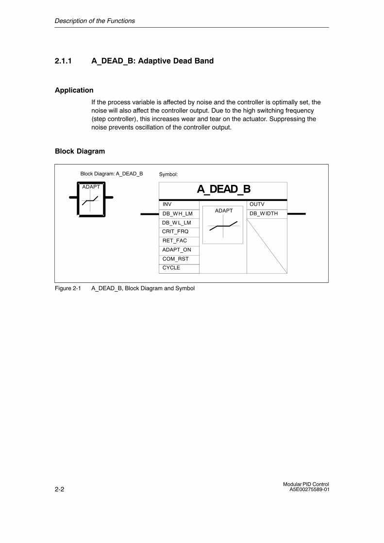
2.1.1 A_DEAD_B: Adaptive Dead Band
Application
If the process variable is affected by noise and the controller is optimally set, thenoise will also affect the controller output. Due to the high switching frequency(step controller), this increases wear and tear on the actuator. Suppressing thenoise prevents oscillation of the controller output.
Block Diagram
Symbol:
A_DEAD_BADAPT
ADAPTINV OUTV
DB_WH_LM DB_WIDTH
ADAPT_ON
DB_W L_LM
CRIT_FRQ
RET_FAC
COM_RST
CYCLE
Block Diagram: A_DEAD_B
Figure 2-1 A_DEAD_B, Block Diagram and Symbol
Description of the Functions
2-3Modular PID ControlA5E00275589-01
Functional Description
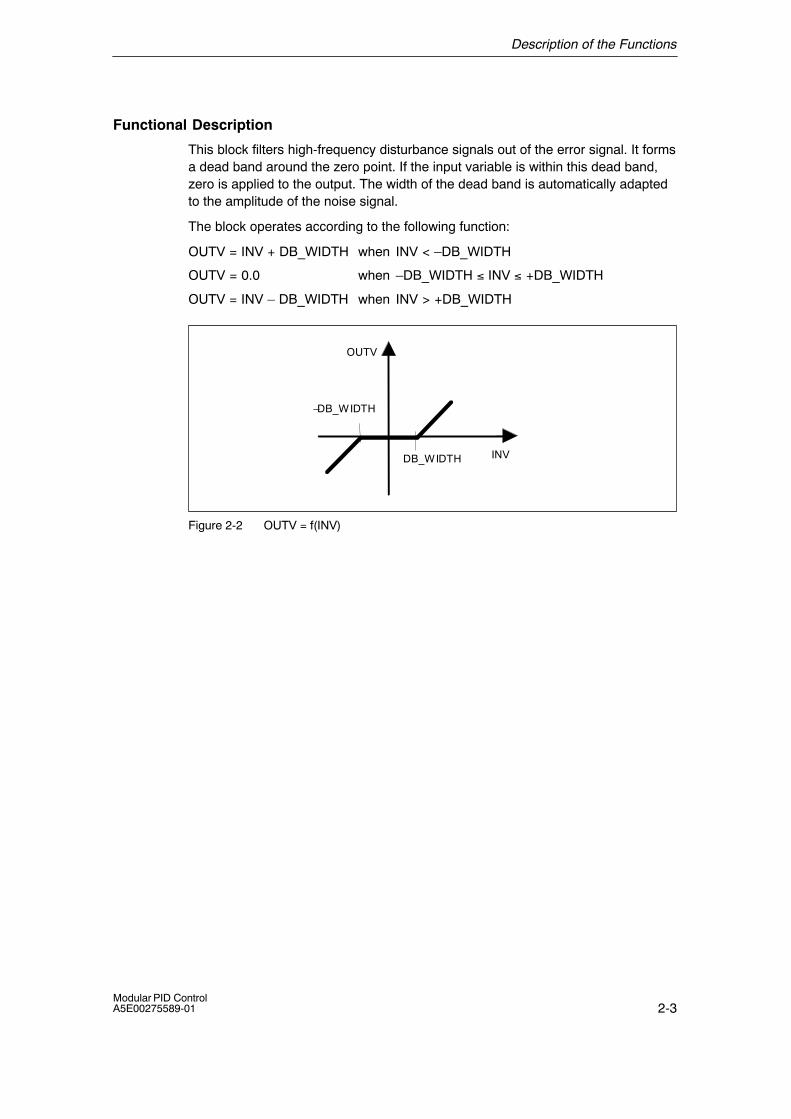
This block filters high-frequency disturbance signals out of the error signal. It formsa dead band around the zero point. If the input variable is within this dead band,zero is applied to the output. The width of the dead band is automatically adaptedto the amplitude of the noise signal.
The block operates according to the following function:
OUTV = INV + DB_WIDTH when INV < �DB_WIDTH
OUTV = 0.0 when �DB_WIDTH ≤ INV ≤ +DB_WIDTH
OUTV = INV � DB_WIDTH when INV > +DB_WIDTH
INV
OUTV
DB_WIDTH
�DB_WIDTH
Figure 2-2 OUTV = f(INV)
Description of the Functions
2-4Modular PID Control
A5E00275589-01
Adaptation of the Dead Band
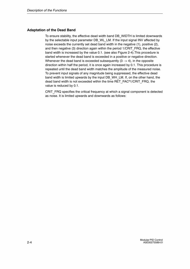
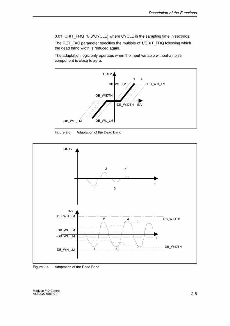
To ensure stability, the effective dead width band DB_WIDTH is limited downwardsby the selectable input parameter DB_WL_LM. If the input signal INV affected bynoise exceeds the currently set dead band width in the negative (1), positive (2),and then negative (3) direction again within the period 1/CRIT_FRQ, the effectiveband width is increased by the value 0.1. (see also Figure 2-4).This procedure isstarted whenever the dead band is exceeded in a positive or negative direction.Whenever the dead band is exceeded subsequently (3 �> 4), in the oppositedirection within half the period, it is once again increased by 0.1. This procedure isrepeated until the dead band width matches the amplitude of the measured noise.To prevent input signals of any magnitude being suppressed, the effective deadband width is limited upwards by the input DB_WH_LM. If, on the other hand, thedead band width is not exceeded within the time RET_FAC*1/CRIT_FRQ, thevalue is reduced by 0.1.
CRIT_FRQ specifies the critical frequency at which a signal component is detectedas noise. It is limited upwards and downwards as follows:
Description of the Functions
2-5Modular PID ControlA5E00275589-01
0.01 CRIT_FRQ 1/(3*CYCLE) where CYCLE is the sampling time in seconds.
The RET_FAC parameter specifies the multiple of 1/CRIT_FRQ following whichthe dead band width is reduced again.
The adaptation logic only operates when the input variable without a noisecomponent is close to zero.
�DB_WH_LM �DB_WL_LM
DB_WH_LM
OUTV
INV
1 4
�DB_WIDTH
DB_WIDTH
DB_WL_LM
Figure 2-3 Adaptation of the Dead Band
1
2
3
4
INV
t
DB_WIDTHDB_WH_LM
DB_WL_LM
�DB_WL_LM
�DB_WIDTH�DB_WH_LM
1
2
3
4
OUTV
t
Figure 2-4 Adaptation of the Dead Band

Description of the Functions
2-6Modular PID Control
A5E00275589-01
Input Parameters
The following table shows the data type and structure of the input parameters ofA_DEAD_B.
Table 2-1 Input Parameters of A_DEAD_B
DataType
Parameter Comment PermittedValues
Default
REAL INV input variable technical rangeof values
0.0
REAL DB_WH_LM dead band width high limit tech. range
> DB_WL_LM
5.0
REAL DB_WL_LM dead band width low limit tech. range
< DB_WH_LM
1.0
REAL CRIT_FRQ critical frequency ≥ 0.01 and
≤1/(3 � CYCLE)
0.1
INT RET_FAC return factor ≥ 1 1
BOOL ADAPT_ON adaptive algorithm on FALSE
BOOL COM_RST complete restart FALSE
TIME CYCLE sampling time ≥ 1ms T#1s
Output Parameters
The following table shows the data type and structure of the output parametersA_DEAD_B.
Table 2-2 Output Parameters of A_DEAD_B
DataType
Parameter Comment Default
REAL OUTV output variable 0.0
REAL DB_WIDTH effective dead band width 0.0

Description of the Functions
2-7Modular PID ControlA5E00275589-01
Complete Restart
During a complete restart, OUTV is set to 0.0 and the effective dead band width isset so that DB_WIDTH = DB_WL_LM.
Normal Operation
The following conditions apply to the adaptation:
• Adaptation Off
If adaptation is turned off (ADAPT_ON = FALSE), the last DB_WIDTH value isfrozen and used as the effective dead band width DB_WIDTH.
• Adaptation On
If ADAPT_ON = TRUE, an adaptation algorithm can be included that calculatesthe effective dead band width. This adapts the dead band width to theamplitude of the noise signal overlaying the input variable so that the noisecomponent is suppressed even when its amplitude fluctuates.
If the block call is acyclic, the adaptation must be turned off (ADAPT_ON =FALSE).
Block-Internal Limits
The values of the input parameters are not restricted in the block; the parametersare not checked.
Example
If the adaptation is turned on due to noise during startup and if a stable dead bandwidth is established after a certain time, the adaptation can be turned off. The deadband width set by the adaptive function is retained until there is a complete restart.
Description of the Functions
2-8Modular PID Control
A5E00275589-01
2.1.2 CRP_IN: Change Range Peripheral Input
Application
The block adapts the range of values of the analog I/Os to the internalrepresentation of the modular controller; it can, for example, be called in theprocess variable branch.
Block Diagram
Symbol:
CRP_INCRP_IN
CRP_IN
INV_PER OUTV
FACTOR
OFFSET
START_ON
STARTVAL
Block Diagram: CPR_IN
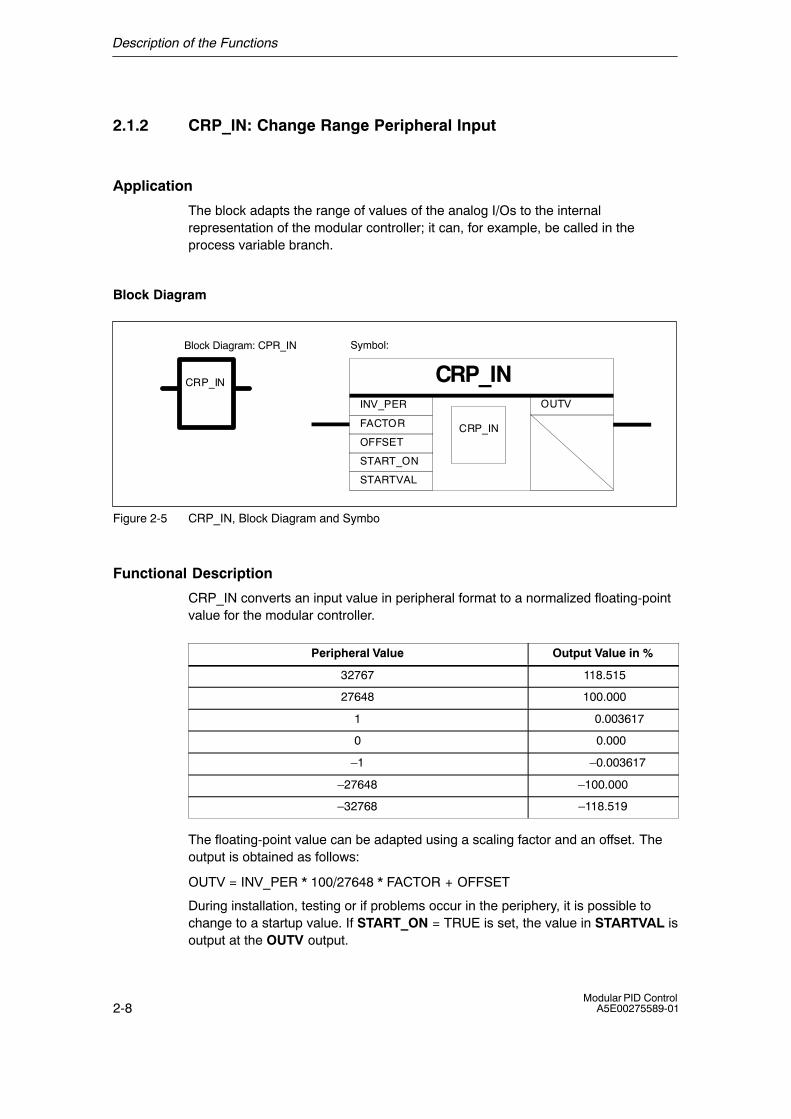
Figure 2-5 CRP_IN, Block Diagram and Symbo
Functional Description
CRP_IN converts an input value in peripheral format to a normalized floating-pointvalue for the modular controller.
Peripheral Value Output Value in %
32767 118.515
27648 100.000
1 0.003617
0 0.000
�1 �0.003617
�27648 �100.000
�32768 �118.519
The floating-point value can be adapted using a scaling factor and an offset. Theoutput is obtained as follows:
OUTV = INV_PER * 100/27648 * FACTOR + OFFSET
During installation, testing or if problems occur in the periphery, it is possible tochange to a startup value. If START_ON = TRUE is set, the value in STARTVAL isoutput at the OUTV output.
Description of the Functions
2-9Modular PID ControlA5E00275589-01
Note
There is no check for positive/negative overflow.
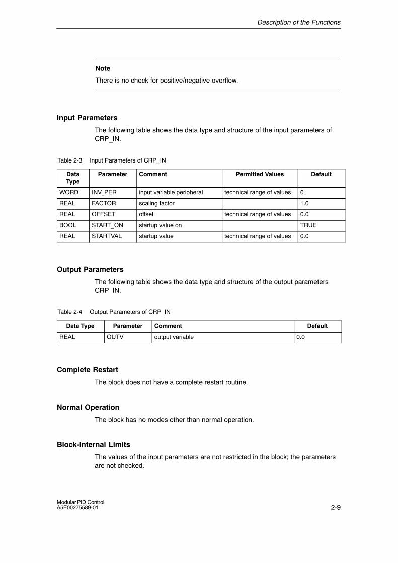
Input Parameters
The following table shows the data type and structure of the input parameters ofCRP_IN.
Table 2-3 Input Parameters of CRP_IN
DataType
Parameter Comment Permitted Values Default
WORD INV_PER input variable peripheral technical range of values 0
REAL FACTOR scaling factor 1.0
REAL OFFSET offset technical range of values 0.0
BOOL START_ON startup value on TRUE
REAL STARTVAL startup value technical range of values 0.0
Output Parameters
The following table shows the data type and structure of the output parametersCRP_IN.
Table 2-4 Output Parameters of CRP_IN
Data Type Parameter Comment Default
REAL OUTV output variable 0.0
Complete Restart
The block does not have a complete restart routine.
Normal Operation
The block has no modes other than normal operation.
Block-Internal Limits
The values of the input parameters are not restricted in the block; the parametersare not checked.

Description of the Functions
2-10Modular PID Control
A5E00275589-01
2.1.3 CRP_OUT: Change Range Peripheral Output
Application
The block adapts a floating-point value of the modular controller to the peripheralformat.
Block Diagram
Block Diagram: CRP_OUT Symbol:
CRP_OUTCRP_OUT
CRP_OUT
INV OUTV_PER
FACTOR
OFFSET
Figure 2-6 CRP_OUT, Block Diagram and Symbol
Functional Description
CRP_OUT converts an input value (normalized floating-point value of the modularcontroller) to the peripheral format of the analog I/Os.
Table 2-5 Input Value/Peripheral Value
Input Value in % Peripheral Value
118.515 32767
100.000 27648
0.003617 1
0.000 0
�0.003617 �1
�100.000 �27648
�118.519 �32768
The floating-point value can be adapted using a scaling factor and an offset. Theoutput is calculated as follows:
OUTV_PER = (INV * FACTOR + OFFSET) * 27648/100
Description of the Functions
2-11Modular PID ControlA5E00275589-01
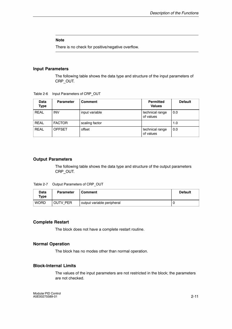
Note
There is no check for positive/negative overflow.
Input Parameters
The following table shows the data type and structure of the input parameters ofCRP_OUT.
Table 2-6 Input Parameters of CRP_OUT
DataType
Parameter Comment PermittedValues
Default
REAL INV input variable technical rangeof values
0.0
REAL FACTOR scaling factor 1.0
REAL OFFSET offset technical rangeof values
0.0
Output Parameters
The following table shows the data type and structure of the output parametersCRP_OUT.
Table 2-7 Output Parameters of CRP_OUT
DataType
Parameter Comment Default
WORD OUTV_PER output variable peripheral 0
Complete Restart
The block does not have a complete restart routine.
Normal Operation
The block has no modes other than normal operation.
Block-Internal Limits
The values of the input parameters are not restricted in the block; the parametersare not checked.

Description of the Functions
2-12Modular PID Control
A5E00275589-01
2.1.4 DEAD_T: Dead Time
Application
This block can be used in ratio controllers when the individual components havedifferent distances to travel before they are brought together.
Block Diagram
Symbol:
DEAD_TOUTVINV
DB_NBR
DEAD_TM
TRACK
COM_RST
CYCLE
Block Diagram: DEAD_T
Figure 2-7 DEAD_T, Block Diagram and Symbol
Functional Description
The block delays the output of an input value by a selectable time (dead time). Theinput values are buffered in a shared data block. The maximum dead time dependson the length of this data block. The data in the shared data block DB_NBR areprocessed in the same way as in a ring buffer.
Table 2-8 Input Value
No. Input Value
0 INV[0] �
1 INV[1] � �
2 INV[2] � ⇔ OUTV/INV read/write pointer
... ... � �
... ... � �
n INV[n] � DEAD_TM = (n+1) • CYCLE
... ...
m INV[m]
Description of the Functions
2-13Modular PID ControlA5E00275589-01
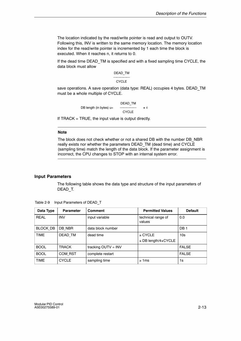
The location indicated by the read/write pointer is read and output to OUTV.Following this, INV is written to the same memory location. The memory locationindex for the read/write pointer is incremented by 1 each time the block isexecuted. When it reaches n, it returns to 0.
If the dead time DEAD_TM is specified and with a fixed sampling time CYCLE, thedata block must allow
DEAD_TM
CYCLE
save operations. A save operation (data type: REAL) occupies 4 bytes. DEAD_TMmust be a whole multiple of CYCLE.
DEAD_TMDB length (in bytes) u= � 4
CYCLE
If TRACK = TRUE, the input value is output directly.
Note
The block does not check whether or not a shared DB with the number DB_NBRreally exists nor whether the parameters DEAD_TM (dead time) and CYCLE(sampling time) match the length of the data block. If the parameter assignment isincorrect, the CPU changes to STOP with an internal system error.
Input Parameters
The following table shows the data type and structure of the input parameters ofDEAD_T.
Table 2-9 Input Parameters of DEAD_T
Data Type Parameter Comment Permitted Values Default
REAL INV input variable technical range ofvalues
0.0
BLOCK_DB DB_NBR data block number DB 1
TIME DEAD_TM dead time ≥ CYCLE
≤ DB length/4�CYCLE
10s
BOOL TRACK tracking OUTV = INV FALSE
BOOL COM_RST complete restart FALSE
TIME CYCLE sampling time ≥ 1ms 1s
Description of the Functions
2-14Modular PID Control
A5E00275589-01
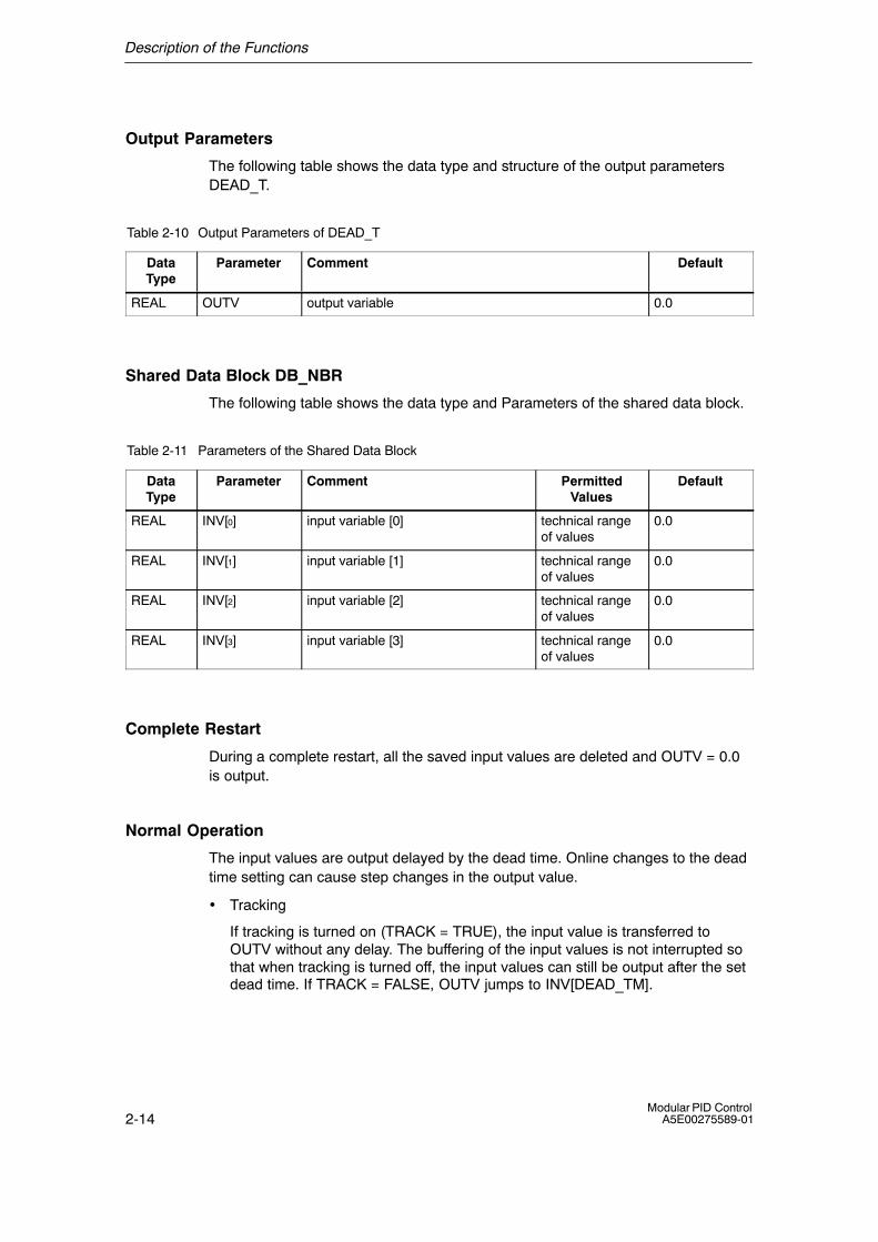
Output Parameters
The following table shows the data type and structure of the output parametersDEAD_T.
Table 2-10 Output Parameters of DEAD_T
DataType
Parameter Comment Default
REAL OUTV output variable 0.0
Shared Data Block DB_NBR
The following table shows the data type and Parameters of the shared data block.
Table 2-11 Parameters of the Shared Data Block
DataType
Parameter Comment PermittedValues
Default
REAL INV[0] input variable [0] technical rangeof values
0.0
REAL INV[1] input variable [1] technical rangeof values
0.0
REAL INV[2] input variable [2] technical rangeof values
0.0
REAL INV[3] input variable [3] technical rangeof values
0.0
Complete Restart
During a complete restart, all the saved input values are deleted and OUTV = 0.0is output.
Normal Operation
The input values are output delayed by the dead time. Online changes to the deadtime setting can cause step changes in the output value.
• Tracking
If tracking is turned on (TRACK = TRUE), the input value is transferred toOUTV without any delay. The buffering of the input values is not interrupted sothat when tracking is turned off, the input values can still be output after the setdead time. If TRACK = FALSE, OUTV jumps to INV[DEAD_TM].
Description of the Functions
2-15Modular PID ControlA5E00275589-01
Block-Internal Limits
The values of the input parameters are not restricted in the block; the parametersare not checked.
Example
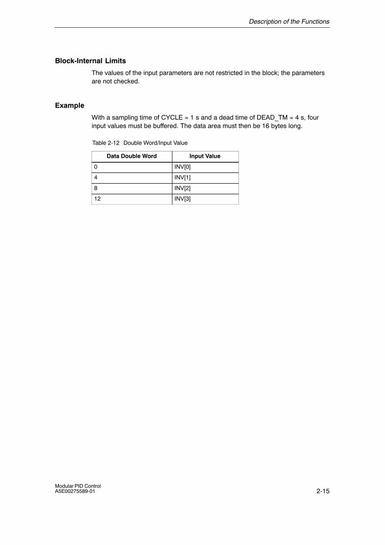
With a sampling time of CYCLE = 1 s and a dead time of DEAD_TM = 4 s, fourinput values must be buffered. The data area must then be 16 bytes long.
Table 2-12 Double Word/Input Value
Data Double Word Input Value
0 INV[0]
4 INV[1]
8 INV[2]
12 INV[3]
Description of the Functions
2-16Modular PID Control
A5E00275589-01
2.1.5 DEADBAND: Dead Band
Application
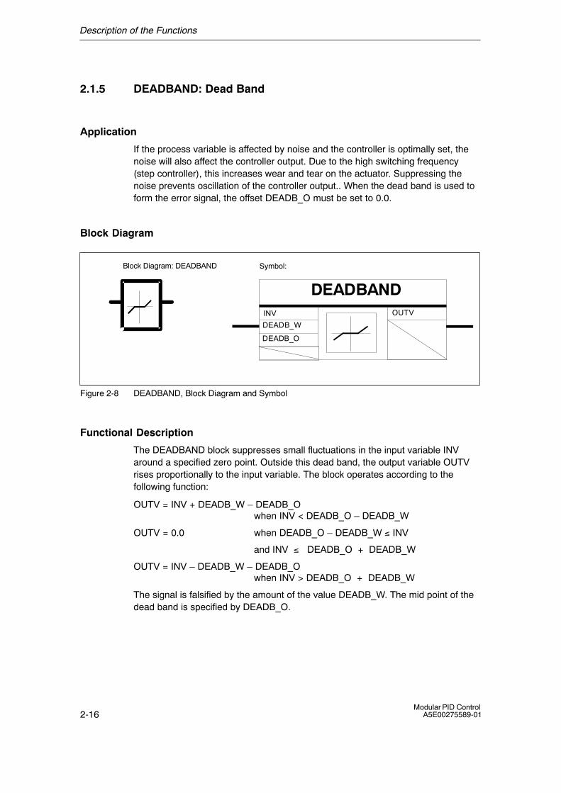
If the process variable is affected by noise and the controller is optimally set, thenoise will also affect the controller output. Due to the high switching frequency(step controller), this increases wear and tear on the actuator. Suppressing thenoise prevents oscillation of the controller output.. When the dead band is used toform the error signal, the offset DEADB_O must be set to 0.0.
Block Diagram
Symbol:
DEADBANDINV
DEADB_W
DEADB_O
OUTV
Block Diagram: DEADBAND
Figure 2-8 DEADBAND, Block Diagram and Symbol
Functional Description
The DEADBAND block suppresses small fluctuations in the input variable INVaround a specified zero point. Outside this dead band, the output variable OUTVrises proportionally to the input variable. The block operates according to thefollowing function:
OUTV = INV + DEADB_W � DEADB_O when INV < DEADB_O � DEADB_W
OUTV = 0.0 when DEADB_O � DEADB_W ≤ INV
and INV ≤ DEADB_O + DEADB_W
OUTV = INV � DEADB_W � DEADB_O when INV > DEADB_O + DEADB_W
The signal is falsified by the amount of the value DEADB_W. The mid point of thedead band is specified by DEADB_O.
Description of the Functions
2-17Modular PID ControlA5E00275589-01
DEADB_O
DEADB_W
OUTV
INV
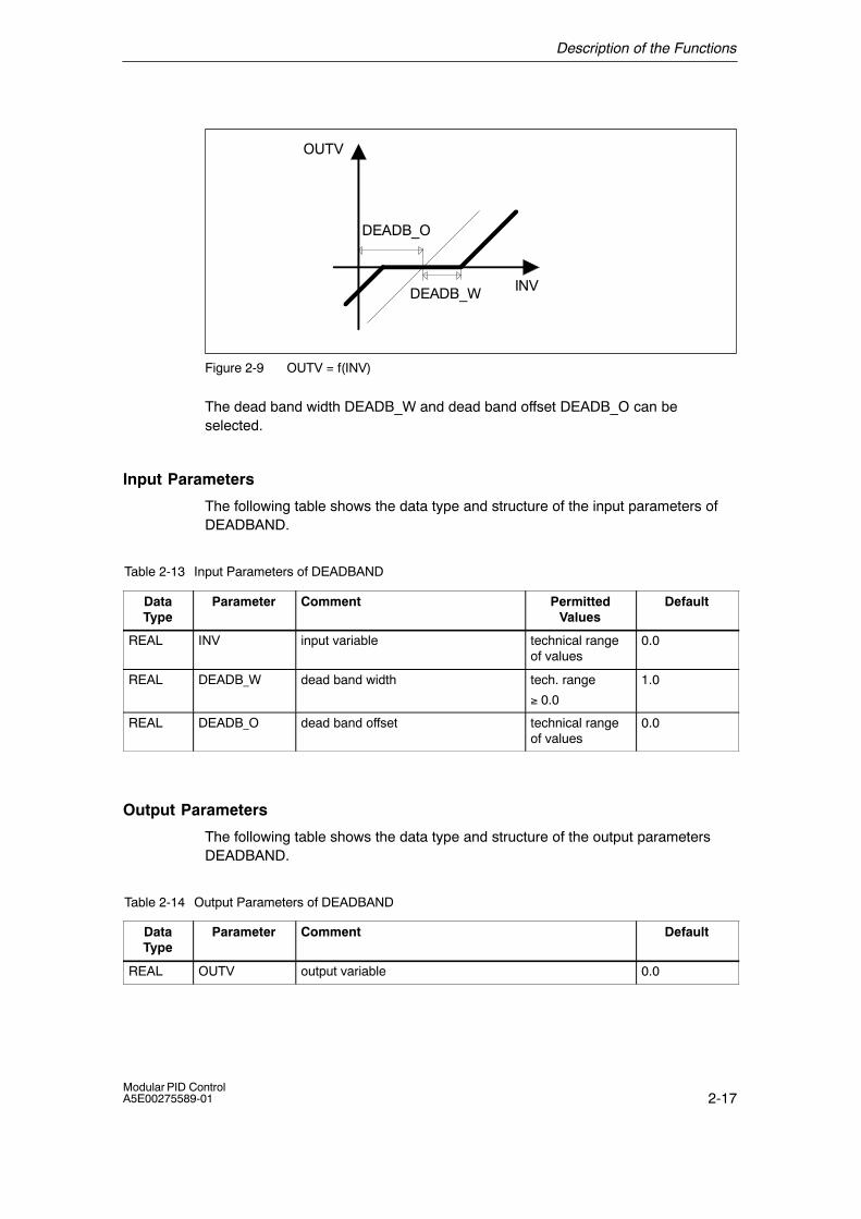
Figure 2-9 OUTV = f(INV)
The dead band width DEADB_W and dead band offset DEADB_O can beselected.
Input Parameters
The following table shows the data type and structure of the input parameters ofDEADBAND.
Table 2-13 Input Parameters of DEADBAND
DataType
Parameter Comment PermittedValues
Default
REAL INV input variable technical rangeof values
0.0
REAL DEADB_W dead band width tech. range
≥ 0.0
1.0
REAL DEADB_O dead band offset technical rangeof values
0.0
Output Parameters
The following table shows the data type and structure of the output parametersDEADBAND.
Table 2-14 Output Parameters of DEADBAND
DataType
Parameter Comment Default
REAL OUTV output variable 0.0
Description of the Functions
2-18Modular PID Control
A5E00275589-01
Complete Restart
The block has no complete restart routine.
Normal Operation
The block has no modes other than normal operation.
Block-Internal Limits
The values of the input parameters are not restricted in the block; the parametersare not checked. The dead band width can only have positive values.
Example
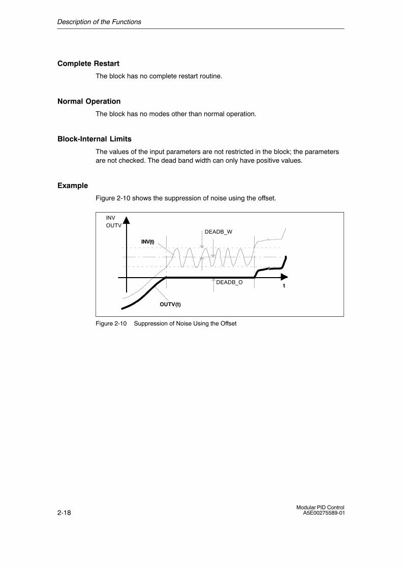
Figure 2-10 shows the suppression of noise using the offset.
INVOUTV
tDEADB_O
DEADB_W
OUTV(t)
INV(t)
t
Figure 2-10 Suppression of Noise Using the Offset
Description of the Functions
2-19Modular PID ControlA5E00275589-01
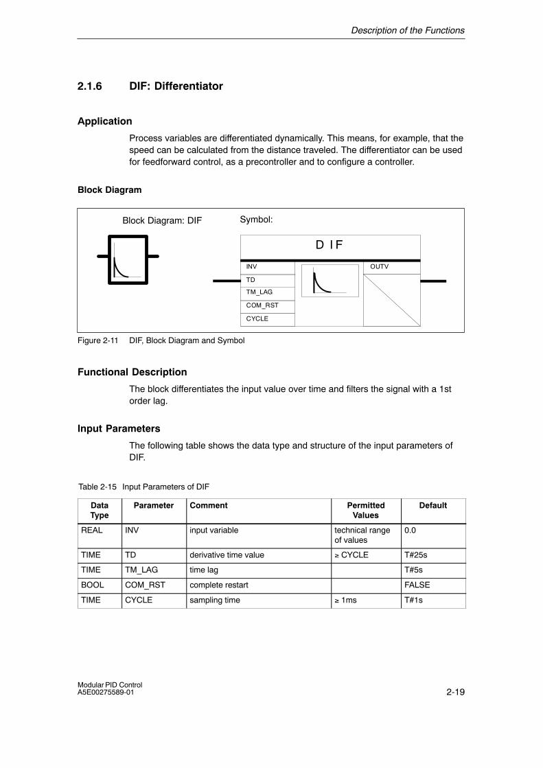
2.1.6 DIF: Differentiator
Application
Process variables are differentiated dynamically. This means, for example, that thespeed can be calculated from the distance traveled. The differentiator can be usedfor feedforward control, as a precontroller and to configure a controller.
Block Diagram
Symbol:
D I F
CYCLE
OUTV
TD
TM_LAG
INV
COM_RST
Block Diagram: DIF
Figure 2-11 DIF, Block Diagram and Symbol
Functional Description
The block differentiates the input value over time and filters the signal with a 1storder lag.
Input Parameters
The following table shows the data type and structure of the input parameters ofDIF.
Table 2-15 Input Parameters of DIF
DataType
Parameter Comment PermittedValues
Default
REAL INV input variable technical rangeof values
0.0
TIME TD derivative time value ≥ CYCLE T#25s
TIME TM_LAG time lag T#5s
BOOL COM_RST complete restart FALSE
TIME CYCLE sampling time ≥ 1ms T#1s
Description of the Functions
2-20Modular PID Control
A5E00275589-01
Output Parameters
The following table shows the data type and structure of the output parametersDIF.
Table 2-16 Output Parameters of DIF
DataType
Parameter Comment Default
REAL OUTV output variable 0.0
Complete Restart
During a complete restart, all the signal outputs are set to 0. Internally, thedifferentiator is assigned the current input value INV. The transition to normaloperation therefore does not cause any step change if the input variable remainsthe same.
Normal Operation
During differentiation, the block operates according to the following transferfunction:
in the Laplace range: OUTV(s) / INV(s) = TD / (1+TM_LAG*s)
The time response of the differentiator is specified by the derivative time TD andthe time lag TM_LAG. The corresponding step response is illustrated in thefollowing diagram.
Description of the Functions
2-21Modular PID ControlA5E00275589-01
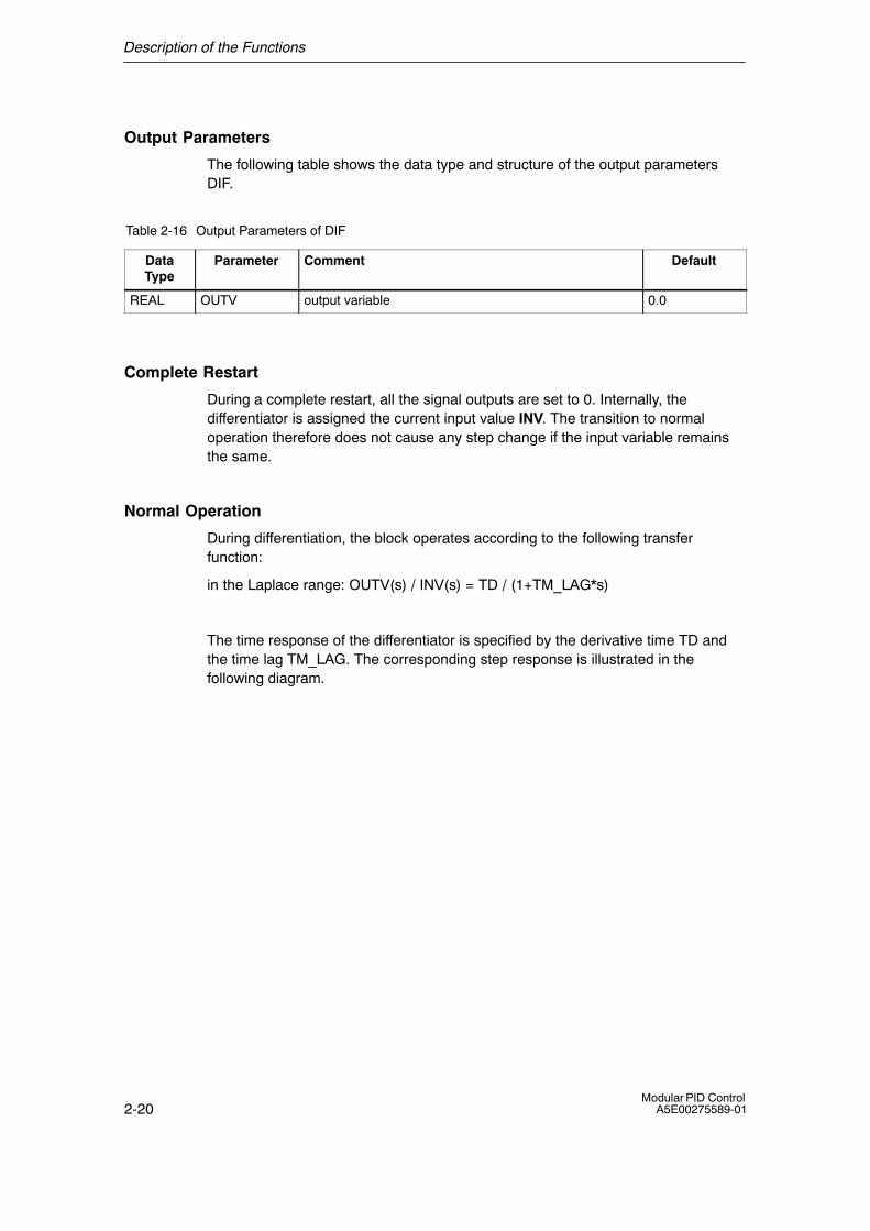
Step Response
Figures 2-12 and 2-13 show the step response of DIF (with and without lag).
INV(t)* INV0
TM_LAGt
OUTV(t) = INV0 * eTD
TM_LAG� t/TM_LAG
TDTM_LAG
where: Derivative timeTime lag constantInput step changeTimeInput variableOutput variable
OUTV(t)
INV, OUTV
TD:TM_LAG:INV0:t:INV:OUTV:
Figure 2-12 Step Response of DIF
If the value assigned for TM_LAG is less than or equal to CYCLE/2, thedifferentiator works without time lag. An input step change is applied to the outputwith the factor TD/CYCLE. After one cycle, the output returns to 0.0 again.
INV(t)* INV0
CYCLEt
TDCYCLE
OUTV(t)
INV, OUTV
Figure 2-13 Step Response of DIF without Lag

Description of the Functions
2-22Modular PID Control
A5E00275589-01
Block-Internal Limits
The derivative time is limited downwards to the sampling time. The time lag islimited downwards to half the sampling time.
TDintern = CYCLE when TD < CYCLE
TM_LAGintern = CYCLE/2 when TM_LAG < CYCLE/2
The values of the other input parameters are not restricted in the block; theparameters are not checked.
Description of the Functions
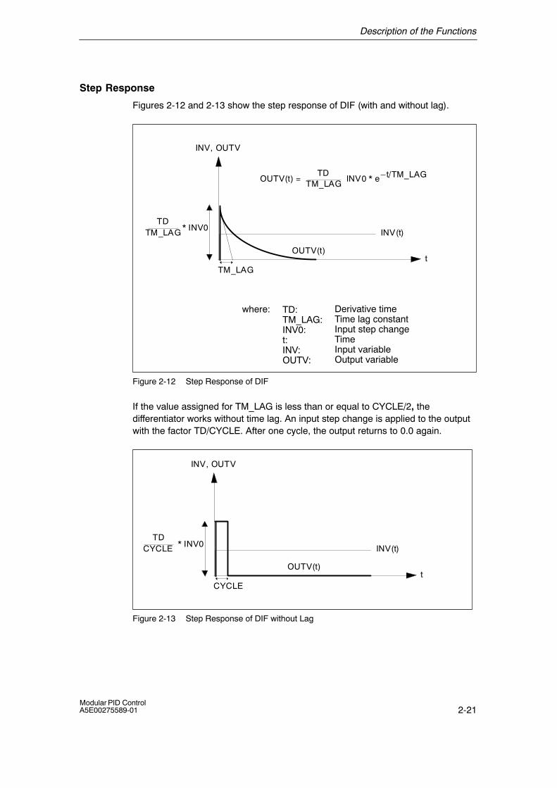
2-23Modular PID ControlA5E00275589-01
2.1.7 ERR_MON: Error Signal Monitoring
Application
The block is used to form and monitor the error signal.
Block Diagram
Symbol:
ERR_MON
ER
PV
SP
SP_DIFF
ER_LM
ER_LMTD
TM_DELAY
TM_RAMP
COM_RST
QER_LM
QER_LMTD
CYCLE
Block Diagram: ERR_MON
Figure 2-14 ERR_MON, Block Diagram and Symbol
Functional Description
The block calculates the error signal ER = SP � PV and monitors it for selectablelimits. If there is a change in the setpoint greater than SP_DIF, the activation of thelimit value signal ER_LM is suppressed for a selectable time(TM_DELAY+TM_RAMP); during this time the higher limit value ER_LMTD of ERis monitored. If ER_LMTD is exceeded, QER_LMTD = TRUE is output. Once thedelay time has expired, ER_LMTD changes to ER_LM according to a rampfunction. The on delay is started by a setpoint change. The slope of the ramp canbe selected with the TM_RAMP parameter.

Description of the Functions
2-24Modular PID Control
A5E00275589-01
ÎÎÎÎÎÎÎÎÎÎÎÎÎÎÎ
t
t
PV
SP
PV
SP
Time delay
ÎÎÎÎÎÎÎÎÎÎÎÎÎÎÎ
Ramp function
PV:SP:ER:t:ER_LM:ER_LMTD:
TM_DELAY
ER_LM
ER_LMTD
ER
Process variableSetpointError signalTimeError signal limitError signal limit during the time delay
ÏÏÏÏÏÏÏÏÏÏÏÏÏÏÏÏÏÏÏÏÏÏÏÏÏÏÏÏÏÏÏÏÏÏÏÏÏÏÏÏÏÏÏÏÏÏÏÏÏ�ER_LMTD
�ER_LM
QER_LMTD
QER_LM
TM_RAMP
ÎÎÎÎÎÎÎÎÎÎÎÎÎÎÎ
TM_DELAY:
TM_RAMP:QER_LM:QER_LMTD:
Time delay of the monitoringsignalRamp time constantError signal limit reached Error signal limit during time delay and ramp reached
Figure 2-15 How ERR_MON Functions
Description of the Functions
2-25Modular PID ControlA5E00275589-01
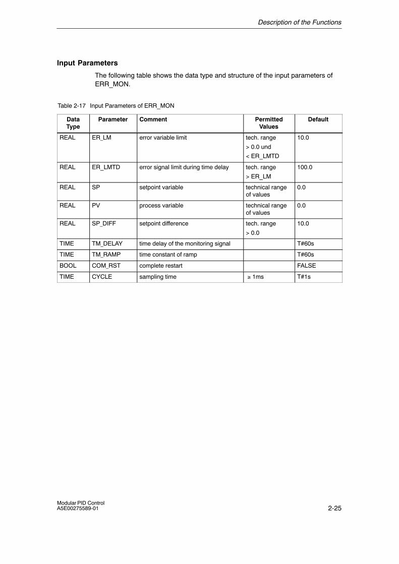
Input Parameters
The following table shows the data type and structure of the input parameters ofERR_MON.
Table 2-17 Input Parameters of ERR_MON
DataType
Parameter Comment PermittedValues
Default
REAL ER_LM error variable limit tech. range
> 0.0 und
< ER_LMTD
10.0
REAL ER_LMTD error signal limit during time delay tech. range
> ER_LM
100.0
REAL SP setpoint variable technical rangeof values
0.0
REAL PV process variable technical rangeof values
0.0
REAL SP_DIFF setpoint difference tech. range
> 0.0
10.0
TIME TM_DELAY time delay of the monitoring signal T#60s
TIME TM_RAMP time constant of ramp T#60s
BOOL COM_RST complete restart FALSE
TIME CYCLE sampling time ≥ 1ms T#1s
Description of the Functions
2-26Modular PID Control
A5E00275589-01
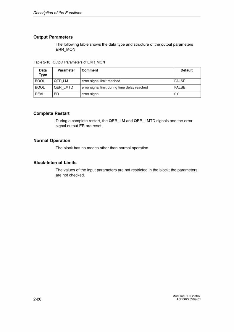
Output Parameters
The following table shows the data type and structure of the output parametersERR_MON.
Table 2-18 Output Parameters of ERR_MON
DataType
Parameter Comment Default
BOOL QER_LM error signal limit reached FALSE
BOOL QER_LMTD error signal limit during time delay reached FALSE
REAL ER error signal 0.0
Complete Restart
During a complete restart, the QER_LM and QER_LMTD signals and the errorsignal output ER are reset.
Normal Operation
The block has no modes other than normal operation.
Block-Internal Limits
The values of the input parameters are not restricted in the block; the parametersare not checked.
Description of the Functions
2-27Modular PID ControlA5E00275589-01
2.1.8 INTEG: Integrator
Application
Process variables are integrated dynamically. This means, for example, that thedistance traveled is calculated from the speed. The integrator can be used toconfigure a controller.
Block Diagram
Symbol:
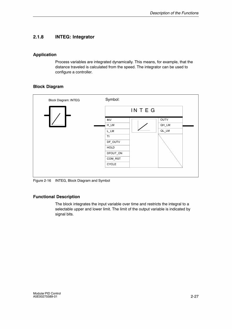
I N T E G
CYCLE
DFOUT_ON
HOLD
OUTV
QH_LM
QL_LM
INV
TI
H_LM
L_LM
DF_OUTV
COM_RST
Block Diagram: INTEG
Figure 2-16 INTEG, Block Diagram and Symbol
Functional Description
The block integrates the input variable over time and restricts the integral to aselectable upper and lower limit. The limit of the output variable is indicated bysignal bits.
Description of the Functions
2-28Modular PID Control
A5E00275589-01
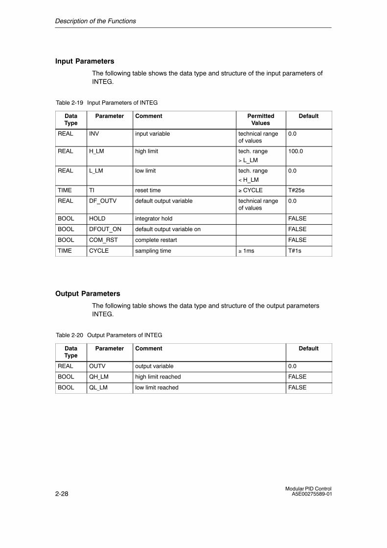
Input Parameters
The following table shows the data type and structure of the input parameters ofINTEG.
Table 2-19 Input Parameters of INTEG
DataType
Parameter Comment PermittedValues
Default
REAL INV input variable technical rangeof values
0.0
REAL H_LM high limit tech. range
> L_LM
100.0
REAL L_LM low limit tech. range
< H_LM
0.0
TIME TI reset time ≥ CYCLE T#25s
REAL DF_OUTV default output variable technical rangeof values
0.0
BOOL HOLD integrator hold FALSE
BOOL DFOUT_ON default output variable on FALSE
BOOL COM_RST complete restart FALSE
TIME CYCLE sampling time ≥ 1ms T#1s
Output Parameters
The following table shows the data type and structure of the output parametersINTEG.
Table 2-20 Output Parameters of INTEG
DataType
Parameter Comment Default
REAL OUTV output variable 0.0
BOOL QH_LM high limit reached FALSE
BOOL QL_LM low limit reached FALSE
Description of the Functions
2-29Modular PID ControlA5E00275589-01
Complete Restart
During a complete restart, the OUTV output is reset to 0.0. If DFOUT_ON = TRUEis set DF_OUTV is output. The limiting of the output remains effective during acomplete restart and the limit signal bits are also effective. When the controllerchanges to normal operation, the block integrates starting at OUTV.
If you want the integrator to start at a particular operating point when a completestart is executed, the operating point must be entered at the input DF_OUTV.When the block is called during the complete restart routine, DFOUT_ON = TRUEmust be set and then reset to DFOUT_ON = FALSE at the cyclic interrupt prioritylevel.

Description of the Functions
2-30Modular PID Control
A5E00275589-01
Normal Operation
In addition to normal operation, the block has the following modes:
Modes DFOUT_ON HOLD
Integrate FALSE FALSE
Integrator hold FALSE TRUE
Default output variable TRUE any
• Integration
When integrating, the block operates according to the following transfer function:
in the Laplace range:OUTV(s) / INV(s) = 1 / (TI�s)
The time response of the integrator is specified by the reset time TI. Thecorresponding step response is illustrated in the following diagram.
INV0
TIt
OUTV(t) = INV0 * t1TI
where : TI:INV0:t:INV:OUTV:
OUTV(t)
INV, OUTV
INV(t)
Reset timeInput step changeTimeInput variableOutput variable
Figure 2-17 Step Response of INTEG
The output and the integrator buffer are restricted to the selectable limit valuesH_LM and L_LM. If the output is within the limits, this is indicated by the signal bitsQH_LM and QL_LM.
Description of the Functions
2-31Modular PID ControlA5E00275589-01
• Integrator Hold
If HOLD is set to TRUE, the integrator remains at its current output value OUTV.When HOLD is reset to FALSE, the integrator continues to integrate starting at thecurrent output value OUTV.
• Default Value at the Output
If DFOUT_ON = TRUE is set, DF_OUTV is applied to the output. The limit iseffective. If this is reset so that DF_OUTV_ON = FALSE is set, the integratorbegins to integrate starting at the value DF_OUTV.
Block-Internal Limits
The reset time is limited downwards by the sampling time:
TIintern = CYCLE when TI < CYCLE
The values of the other input parameters are not restricted in the block; theparameters are not checked.
Description of the Functions
2-32Modular PID Control
A5E00275589-01
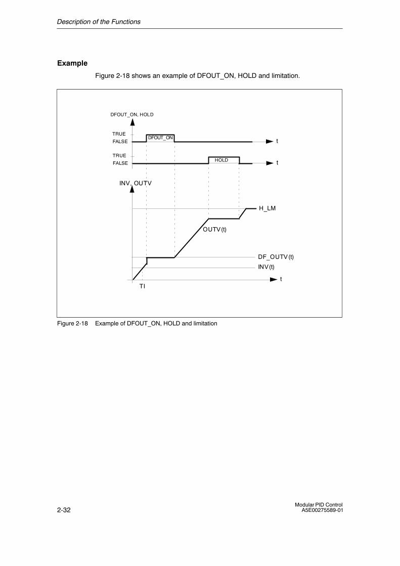
Example
Figure 2-18 shows an example of DFOUT_ON, HOLD and limitation.
t
INV, OUTV
TI
OUTV(t)
INV(t)
DF_OUTV(t)
H_LM
tHOLDTRUE
FALSE
tDFOUT_ON
TRUE
FALSE
DFOUT_ON, HOLD
Figure 2-18 Example of DFOUT_ON, HOLD and limitation
Description of the Functions
2-33Modular PID ControlA5E00275589-01
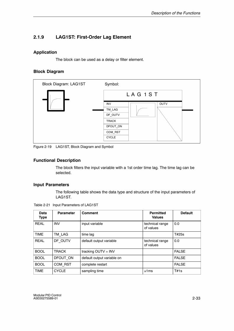
2.1.9 LAG1ST: First-Order Lag Element
Application
The block can be used as a delay or filter element.
Block Diagram
Symbol:
L A G 1 S T
CYCLE
DFOUT_ON
TRACK
OUTVINV
TM_LAG
DF_OUTV
COM_RST
Block Diagram: LAG1ST
Figure 2-19 LAG1ST, Block Diagram and Symbol
Functional Description
The block filters the input variable with a 1st order time lag. The time lag can beselected.
Input Parameters
The following table shows the data type and structure of the input parameters ofLAG1ST.
Table 2-21 Input Parameters of LAG1ST
DataType
Parameter Comment PermittedValues
Default
REAL INV input variable technical rangeof values
0.0
TIME TM_LAG time lag T#25s
REAL DF_OUTV default output variable technical rangeof values
0.0
BOOL TRACK tracking OUTV = INV FALSE
BOOL DFOUT_ON default output variable on FALSE
BOOL COM_RST complete restart FALSE
TIME CYCLE sampling time ≥1ms T#1s
Description of the Functions
2-34Modular PID Control
A5E00275589-01
Output Parameters
The following table shows the data type and structure of the output parametersLAG1ST.
Table 2-22 Output Parameters of LAG1ST
DataType
Parameter Comment Default
REAL OUTV output variable 0.0
Complete Restart
During a complete restart, the output OUTV is reset to 0.0. If DFOUT_ON = TRUEis set, DF_OUTV is output. When the controller changes to normal operation, theblock continues to operate starting from OUTV.
Normal Operation
Apart from normal operation, the block has the following modes:

Description of the Functions
2-35Modular PID ControlA5E00275589-01
Modes DFOUT_ON HOLD
Filtering FALSE FALSE
Tracking FALSE TRUE
Default output variable TRUE any
• Filtering
When filtering, the block operates according to the following transfer function:
in the Laplace range: OUTV(s) / INV(s) = 1 / (1+TM_LAG�s)
The time response of the lag element is specified by the time lag TM_LAG. Thecorresponding step response is shown in the following figure.
t
OUTV(t) =INV0 ( 1 � e )
where:
INV, OUTV
�tTM_LAG
INV0
TM_LAG
Input variableOutput variableInput step changeTime lag constant
OUTV(t)
INV(t)
INV:OUTV:INV0:TM_LAG:
Figure 2-20 Step Response of LAG1ST
• Tracking
If TRACK = TRUE, the input value INV is switched to the output OUTV.
• Default Value at the Output
If DFOUT_ON = TRUE is set, DF_OUTV is applied to the output. If this is reset sothat DF_OUTV_ON = FALSE is set, the lag element filters starting from the valueDF_OUTV.
Description of the Functions
2-36Modular PID Control
A5E00275589-01
Block-Internal Limits
The time lag is limited downwards to half the sampling time.
TM_LAGintern = CYCLE/2 when TM_LAG < CYCLE/2
The values of the other input parameters are not restricted in the block; theparameters are not checked.
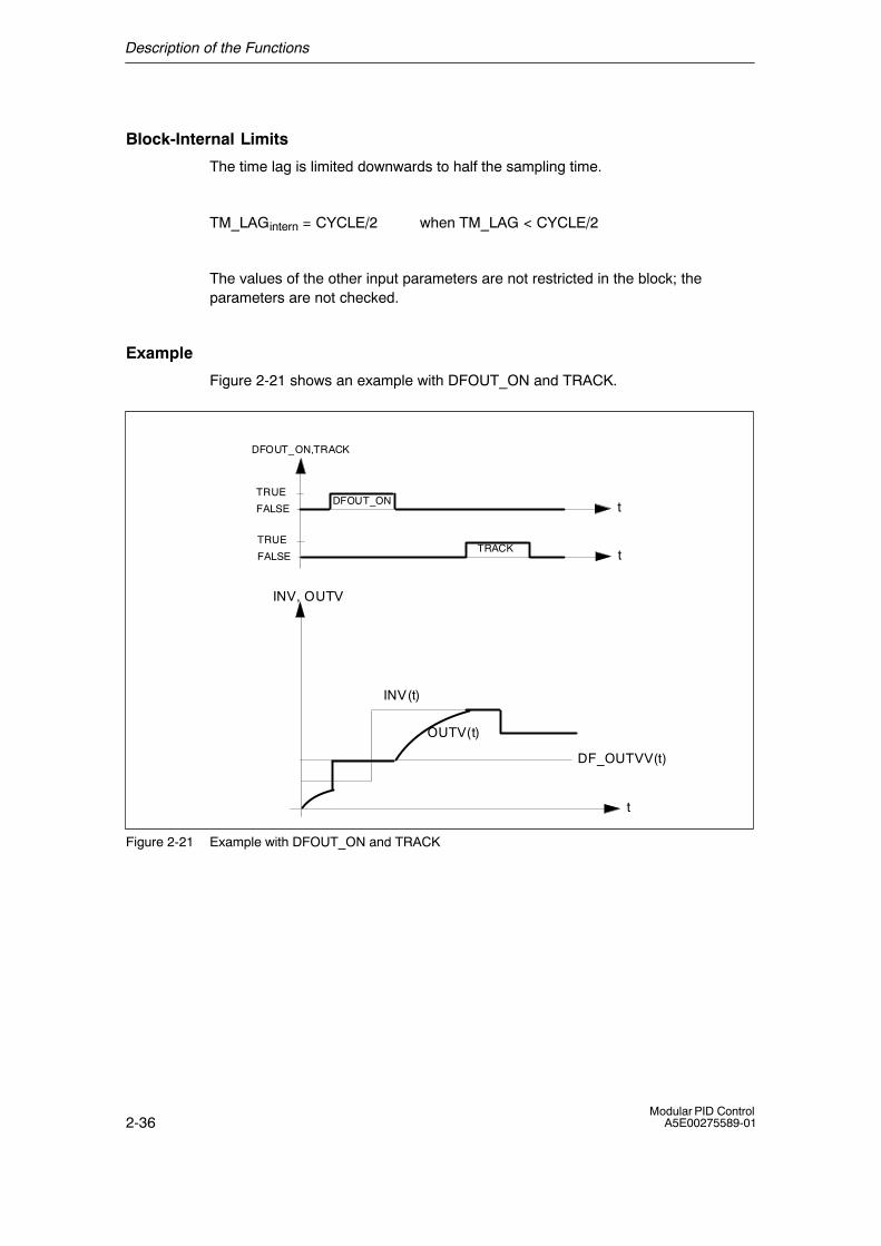
Example
Figure 2-21 shows an example with DFOUT_ON and TRACK.
t
INV, OUTV
OUTV(t)
INV(t)
tTRACK
TRUE
FALSE
DF_OUTVV(t)
tDFOUT_ONTRUE
FALSE
DFOUT_ON,TRACK
Figure 2-21 Example with DFOUT_ON and TRACK
Description of the Functions
2-37Modular PID ControlA5E00275589-01
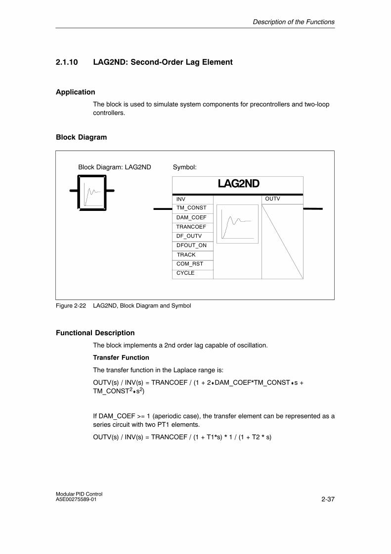
2.1.10 LAG2ND: Second-Order Lag Element
Application
The block is used to simulate system components for precontrollers and two-loopcontrollers.
Block Diagram
Symbol:
LAG2NDINV OUTV
DF_OUTV
DFOUT_ON
TRACK
DAM_COEF
TM_CONST
TRANCOEF
COM_RST
CYCLE
Block Diagram: LAG2ND
Figure 2-22 LAG2ND, Block Diagram and Symbol
Functional Description
The block implements a 2nd order lag capable of oscillation.
Transfer Function
The transfer function in the Laplace range is:
OUTV(s) / INV(s) = TRANCOEF / (1 + 2�DAM_COEF*TM_CONST�s +TM_CONST2�s2)
If DAM_COEF >= 1 (aperiodic case), the transfer element can be represented as aseries circuit with two PT1 elements.
OUTV(s) / INV(s) = TRANCOEF / (1 + T1*s) * 1 / (1 + T2 * s)
Description of the Functions
2-38Modular PID Control
A5E00275589-01
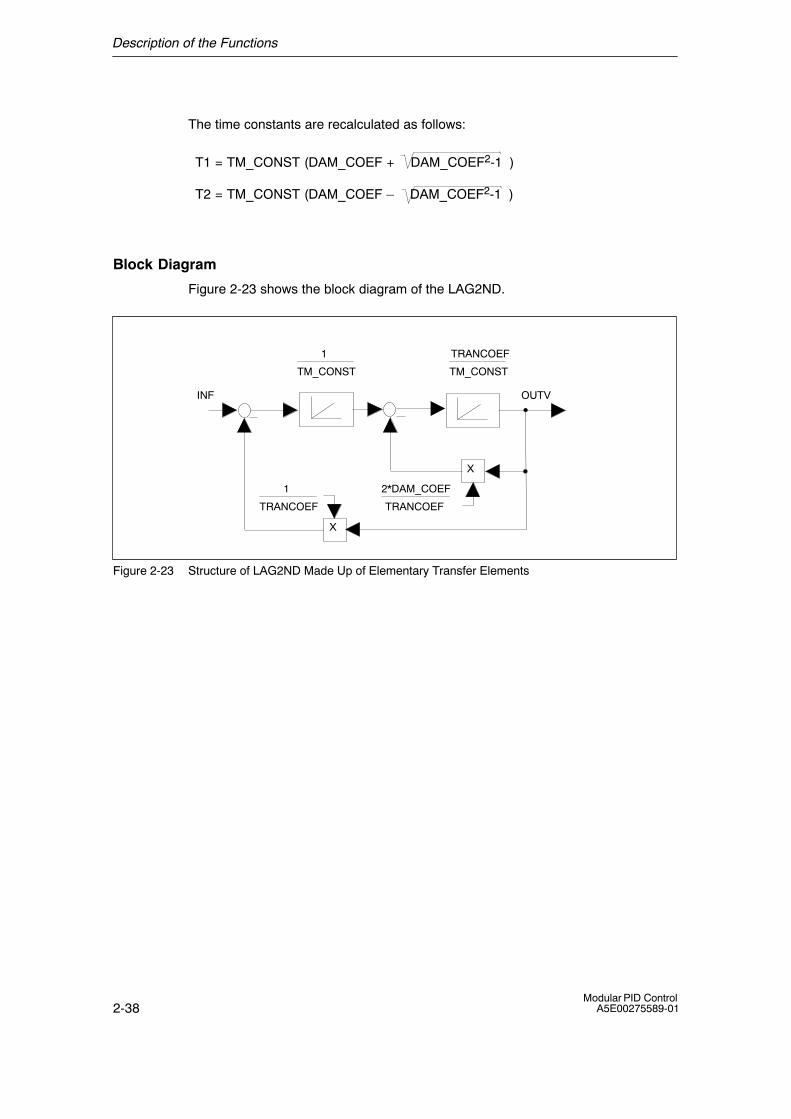
The time constants are recalculated as follows:
T1 = TM_CONST (DAM_COEF + DAM_COEF2-1 )
T2 = TM_CONST (DAM_COEF � DAM_COEF2-1 )
Block Diagram
Figure 2-23 shows the block diagram of the LAG2ND.
X
X
INF
TRANCOEF
1
TM_CONST
TRANCOEF
TRANCOEF
2*DAM_COEF
TM_CONST
1
OUTV
Figure 2-23 Structure of LAG2ND Made Up of Elementary Transfer Elements

Description of the Functions
2-39Modular PID ControlA5E00275589-01
Step Response
t
OUTV(t) = TRANCOEF + e sin( t � phi )
INV(t)
TRANCOEF
1
tan phi =
TRANCOEF
1 � DAM_COEF2 TM_CONST
1 � DAM_COEF2DAM_COEFTM_CONST
t
DAM_COEF
1 � DAM_COEF 2
OUTV(t)
Output variableInput variableTransfer coefficientTime lag constantDamping coefficientSupplementary angle
O UTVIN V
_
where:
OUTV(t):INV(t):TRANCOEF:TM_LAG:DAM_COEF:phi:
Figure 2-24 Step Response of the LAG2ND Element Capable of Oscillation
Input Parameters
The following table shows the data type and structure of the input parameters ofLAG2ND.
Table 2-23 Input Parameters of LAG2ND
DataType
Parameter Comment PermittedValues
Default
REAL INV input variable technical rangeof values
0.0
TIME TM_CONST time constant T#10s
REAL DAM_COEF damping coefficient 1.0
REAL TRANCOEF transfer coefficient 1.0
REAL DF_OUTV default output variable technical rangeof values
0.0
BOOL DFOUT_ON default output variable on FALSE
BOOL TRACK tracking OUTV = INV FALSE
BOOL COM_RST complete restart FALSE
TIME CYCLE sampling time ≥ 1ms T#1s
Description of the Functions
2-40Modular PID Control
A5E00275589-01
Output Parameters
The following table shows the data type and structure of the output parametersLAG2ND.
Table 2-24 Output Parameters of LAG2ND
DataType
Parameter Comment Default
REAL OUTV output variable 0.0
Complete Restart
During a complete restart, output OUTV is set to 0.0. If DFOUT_ON = TRUE, thenDF_OUTV is output.
Normal Operation
Apart from normal operation, the block has the following modes:
• Tracking
If TRACK = TRUE is set, then OUTV = INV; the internal historical values are set toINV.
• Default at the Output
If DFOUT_ON = TRUE is set, then DF_OUTV is output, the internal historicalvalues are set to DF_OUTV. DFOUT_ON has higher priority than TRACK.
Block-Internal Limits
The time constant TM_CONST is limited downwards to half the sampling time.
TM_CONSTintern = CYCLE/2 when TM_CONST < CYCLE/2
The values of the other input parameters are not restricted in the block; theparameters are not checked.

Description of the Functions
2-41Modular PID ControlA5E00275589-01
2.1.11 LIMALARM: Limit Alarm
Application
Illegal or dangerous states can occur in a system if process values (for example,motor speed, temperature or pressure) exceed or fall below critical values. Suchlimit violations must be detected and signaled to allow an appropriate reaction.
Block Diagram
LIMALARM
COM_RST
INV
L_LM_ALM
L_LM_W RN
H_LM_WRN
H_LM_ALM
HYS
QL_LMALM
QL_LMWRN
QH_LMWRN
QH_LMALM
Block Diagram: LIMALARM Symbol:
Figure 2-25 LIMALARM, Block Diagram and Symbol
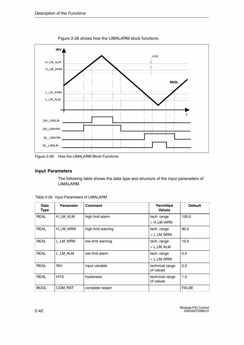
Functional Description
Four limit values can be selected for the input variable INV. If one of these limits isreached and exceeded, a limit signal is output. A hysteresis can be set for the offthreshold.
Description of the Functions
2-42Modular PID Control
A5E00275589-01
Figure 2-26 shows how the LIMALARM block functions:
t
INV
INV(t)
QH_LMALM
QH_LMWRN
QL_LMWRN
QL_LMALM
HYS
H_LM_ALM
L_LM_WRN
H_LM_WRN
L_LM_ALM
Figure 2-26 How the LIMALARM Block Functions
Input Parameters
The following table shows the data type and structure of the input parameters ofLIMALARM.
Table 2-25 Input Parameters of LIMALARM
DataType
Parameter Comment PermittedValues
Default
REAL H_LM_ALM high limit alarm tech. range
> H_LM_WRN
100.0
REAL H_LM_WRN high limit warning tech. range
> L_LM_WRN
90.0
REAL L_LM_WRN low limit warning tech. range
> L_LM_ALM
10.0
REAL L_LM_ALM low limit alarm tech. range
< L_LM_WRN
0.0
REAL INV input variable technical rangeof values
0.0
REAL HYS hysteresis technical rangeof values
1.0
BOOL COM_RST complete restart FALSE
Description of the Functions
2-43Modular PID ControlA5E00275589-01
Output Parameters
The following table shows the data type and structure of the output parametersLIMALARM.
Table 2-26 Output Parameters of LIMALARM
DataType
Parameter Comment Default
BOOL QH_LMALM high limit alarm reached FALSE
BOOL QH_LMWRN high limit warning reached FALSE
BOOL QL_LMWRN low limit warning reached FALSE
BOOL QL_LMALM low limit alarm reached FALSE
Complete Restart
During a complete restart, all the signal outputs are set to FALSE.
Description of the Functions
2-44Modular PID Control
A5E00275589-01
Normal Operation
The block operates according to the following functions:
QH_LMALM = TRUE if INV rises and INV >= H_LM_ALM
or INV falls and INV >= H_LM_ALM � HYS
QH_LMWRN = TRUE if INV rises and INV >= H_LM_WRN
or INV falls and INV >= H_LM_WRN � HYS
QL_LMWRN = TRUE if INV falls and INV <= L_LM_WRN
or INV rises and INV <= L_LM_WRN + HYS
QL_LMALM = TRUE if INV falls and INV <= L_LM_ALM
or INV rises and INV <= L_LM_ALM + HYS
The block can only function properly when:
L_LM_ALM < L_LM_WRN < H_LM_WRN < H_LM_ALM
The limits are set at the inputs H_LM_ALM, H_LM_WRN, L_LM_WRN andL_LM_ALM. If the input variable INV exceeds the limits, the output signal bitsQH_LMALM, QH_LMWRN, QL_LMWRN and QL_LMALM are set. To avoid fastsetting and resetting of the signal bits, the input value must also overcome ahysteresis HYS before the outputs are reset.
Block-Internal Limits
The values of the parameters are not limited in the block; the parameters are notchecked.
Description of the Functions
2-45Modular PID ControlA5E00275589-01
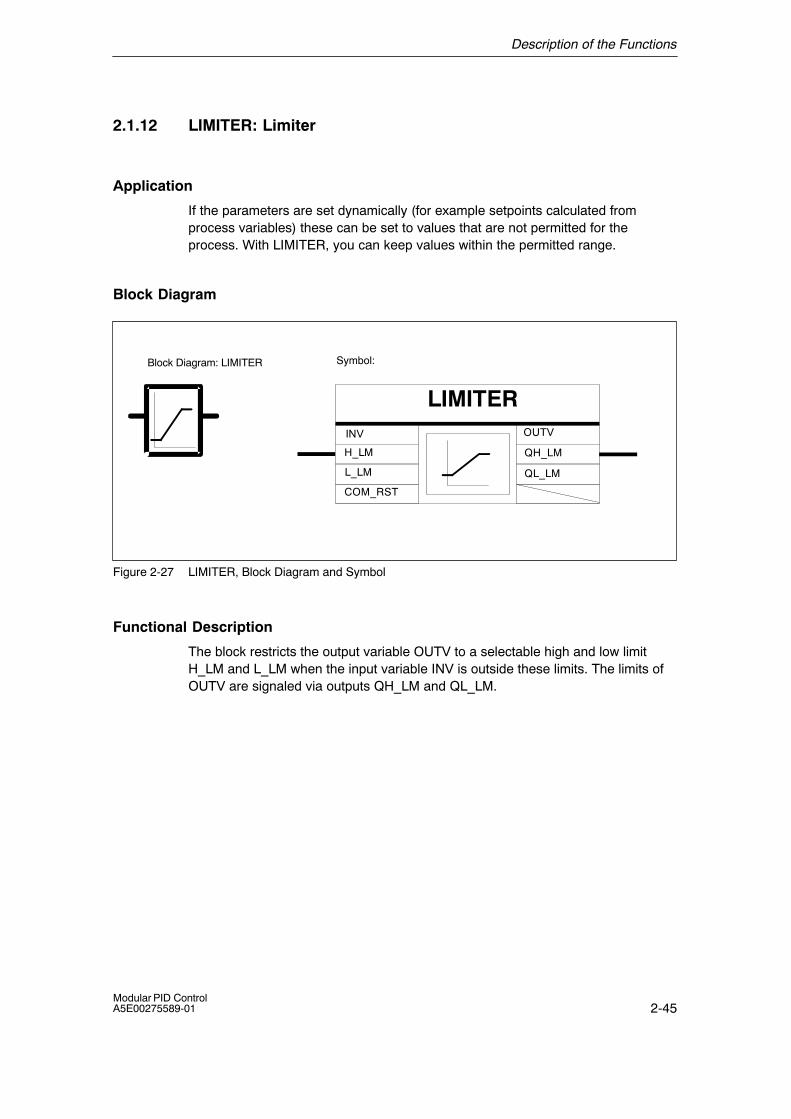
2.1.12 LIMITER: Limiter
Application
If the parameters are set dynamically (for example setpoints calculated fromprocess variables) these can be set to values that are not permitted for theprocess. With LIMITER, you can keep values within the permitted range.
Block Diagram
Symbol:
LIMITERINV
H_LM
L_LM
OUTV
QH_LM
QL_LM
COM_RST
Block Diagram: LIMITER
Figure 2-27 LIMITER, Block Diagram and Symbol
Functional Description
The block restricts the output variable OUTV to a selectable high and low limitH_LM and L_LM when the input variable INV is outside these limits. The limits ofOUTV are signaled via outputs QH_LM and QL_LM.
Description of the Functions
2-46Modular PID Control
A5E00275589-01
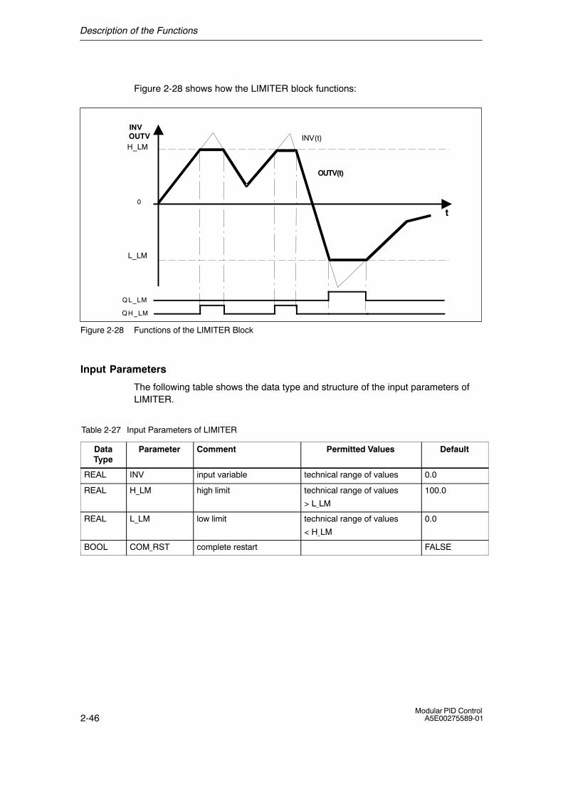
Figure 2-28 shows how the LIMITER block functions:
0
L_LM
H_LM
t
INVOUTV
Q L_LM
Q H_LM
OUTV(t)
INV(t)
Figure 2-28 Functions of the LIMITER Block
Input Parameters
The following table shows the data type and structure of the input parameters ofLIMITER.
Table 2-27 Input Parameters of LIMITER
DataType
Parameter Comment Permitted Values Default
REAL INV input variable technical range of values 0.0
REAL H_LM high limit technical range of values
> L_LM
100.0
REAL L_LM low limit technical range of values
< H_LM
0.0
BOOL COM_RST complete restart FALSE
Description of the Functions
2-47Modular PID ControlA5E00275589-01
Output Parameters
The following table shows the data type and structure of the output parametersLIMITER.
Table 2-28 Output Parameters of LIMITER
DataType
Parameter Comment Default
REAL OUTV output variable 0.0
BOOL QH_LM high limit reached FALSE
BOOL QL_LM low limit reached FALSE
Complete Restart
During a complete restart, all signal outputs are set to FALSE; 0.0 is output atOUTV.
Normal Operation
The block operates according to the following functions:
OUTV = H_LM, QH_LM = TRUE, QL_LM = FALSE if INV >= H_LM
OUTV = L_LM, QH_LM = FALSE, QL_LM = TRUE if INV <= L_LM
OUTV = INV, QH_LM = FALSE, QL_LM = FALSEif L_LM < INV < H_LM
The block can only operate correctly when: L_LM < H_LM.
Block-Internal Limits
The values of the parameters are not limited in the block; the parameters are notchecked.
Description of the Functions
2-48Modular PID Control
A5E00275589-01
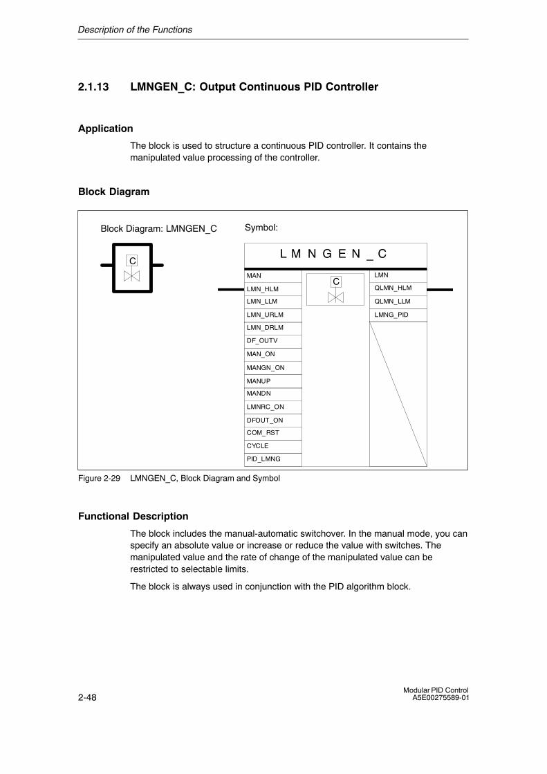
2.1.13 LMNGEN_C: Output Continuous PID Controller
Application
The block is used to structure a continuous PID controller. It contains themanipulated value processing of the controller.
Block Diagram
Symbol:
L M N G E N _ C
CYCLE
DFOUT_ON
MAN_ON
LMN
QLMN_HLM
QLMN_LLM
MANUP
MANDN
LMNRC_ON
DF_OUTV
MANGN_ON
C
CLMN_HLM
LMN_LLM
LMN_URLM
LMN_DRLM
MAN
COM_RST
PID_LMNG
LMNG_PID
Block Diagram: LMNGEN_C
Figure 2-29 LMNGEN_C, Block Diagram and Symbol
Functional Description
The block includes the manual-automatic switchover. In the manual mode, you canspecify an absolute value or increase or reduce the value with switches. Themanipulated value and the rate of change of the manipulated value can berestricted to selectable limits.
The block is always used in conjunction with the PID algorithm block.
Description of the Functions
2-49Modular PID ControlA5E00275589-01
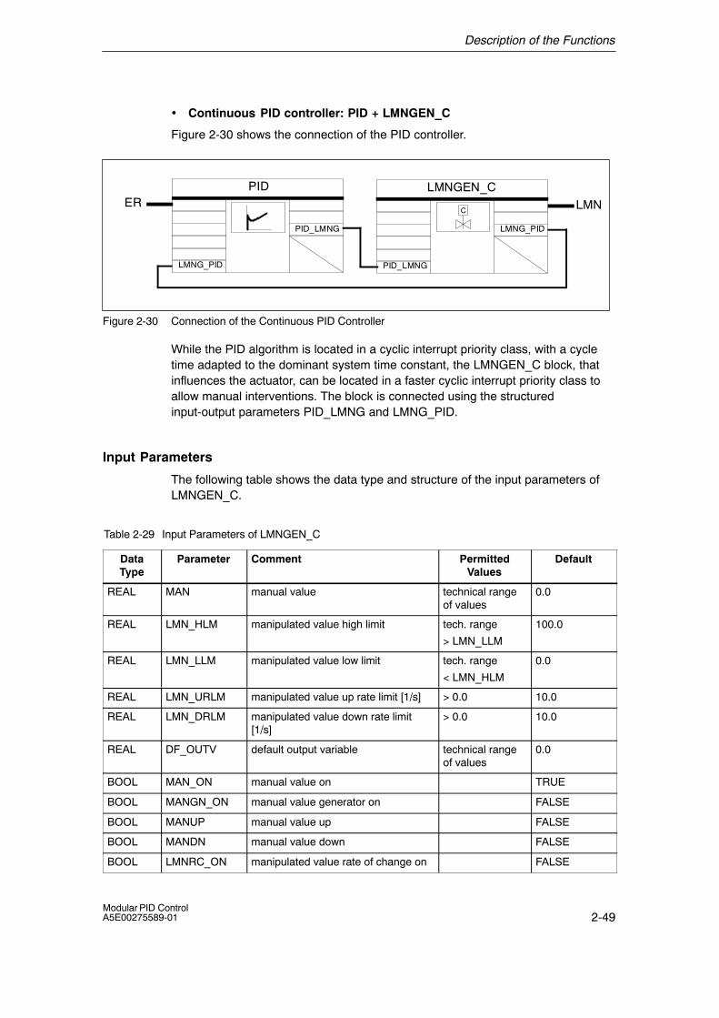
• Continuous PID controller: PID + LMNGEN_C
Figure 2-30 shows the connection of the PID controller.
LMNGEN_C
C
PID_LMNG
LMN
PID
PID_LMNG
ER
LMNG_PID
LMNG_PID
Figure 2-30 Connection of the Continuous PID Controller
While the PID algorithm is located in a cyclic interrupt priority class, with a cycletime adapted to the dominant system time constant, the LMNGEN_C block, thatinfluences the actuator, can be located in a faster cyclic interrupt priority class toallow manual interventions. The block is connected using the structuredinput-output parameters PID_LMNG and LMNG_PID.
Input Parameters
The following table shows the data type and structure of the input parameters ofLMNGEN_C.
Table 2-29 Input Parameters of LMNGEN_C
DataType
Parameter Comment PermittedValues
Default
REAL MAN manual value technical rangeof values
0.0
REAL LMN_HLM manipulated value high limit tech. range
> LMN_LLM
100.0
REAL LMN_LLM manipulated value low limit tech. range
< LMN_HLM
0.0
REAL LMN_URLM manipulated value up rate limit [1/s] > 0.0 10.0
REAL LMN_DRLM manipulated value down rate limit[1/s]
> 0.0 10.0
REAL DF_OUTV default output variable technical rangeof values
0.0
BOOL MAN_ON manual value on TRUE
BOOL MANGN_ON manual value generator on FALSE
BOOL MANUP manual value up FALSE
BOOL MANDN manual value down FALSE
BOOL LMNRC_ON manipulated value rate of change on FALSE
Description of the Functions
2-50Modular PID Control
A5E00275589-01
Table 2-29 Input Parameters of LMNGEN_C, continued
DataType
DefaultPermittedValues
CommentParameter
BOOL DFOUT_ON default output variable on FALSE
BOOL COM_RST complete restart FALSE
TIME CYCLE sampling time ≥ 1ms T#1s
STRUC PID_LMNG PID-LMNGEN interface
Output Parameters
The following table shows the data type and structure of the output parametersLMNGEN_C.
Table 2-30 Output Parameters of LMNGEN_C
DataType
Parameter Comment Default
REAL LMN manipulated value 0.0
BOOL QLMN_HLM high limit of manipulated value reached FALSE
BOOL QLMN_LLM low limit of manipulated value reached FALSE
STRUC LMNG_PID PID-LMNGEN interface
Complete Restart
During a complete restart, the default value DF_OUTV is switched to the LMNoutput regardless of the default bit DFOUT_ON. The limitation of the output andthe limit signal bits are also effective in a complete restart. When the controllerchanges to normal operation, the block continues to operate starting withDF_OUTV.
Normal Operation
Apart from normal operation, the block has the following modes:
Description of the Functions
2-51Modular PID ControlA5E00275589-01
Modes DFOUT_ON MAN_ON
Automatic FALSE FALSE
Manual FALSE TRUE
Default output variable TRUE any
MAN_ON
MAN
0
1
0
1
MANGN_ON
0
1
DFOUT_ON
0
1
DF_OUTV
LMN_OP
MP1
LMNOP_ON
0
1
Manipulated value processingQLMN_HLMQLMN_LLM
LMN_HLM
LMN_LLM
LMN_URLM
LMN_DRLM
LMN_ROC
LMNRC_ON
LMN
PID_LMNGPID_OUTV
MANUPMANDN
MAN_GEN
Manual value processing
LMNLIMIT
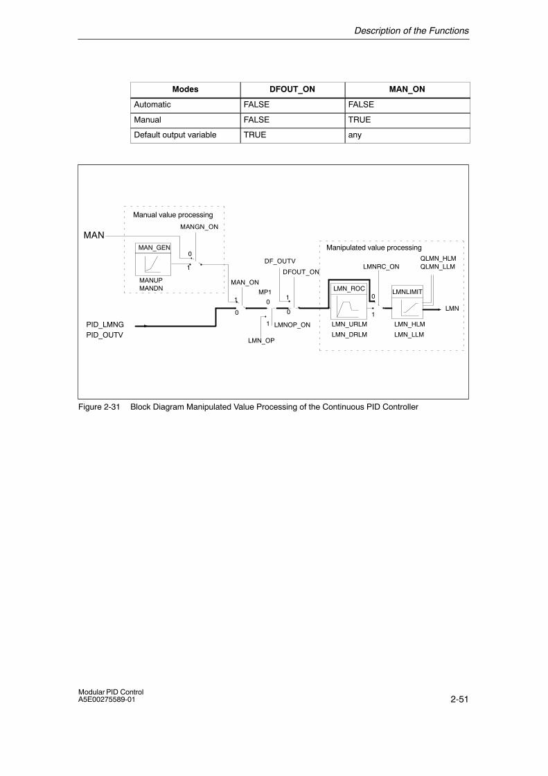
Figure 2-31 Block Diagram Manipulated Value Processing of the Continuous PID Controller
Description of the Functions
2-52Modular PID Control
A5E00275589-01
• Automatic Mode
If no other mode is selected, the value calculated by the PID algorithm istransferred to manipulated value processing. The switchover to the automaticmode does not cause any sudden change if the manipulated value rate of changefunction is activated (LMNRC_ON = TRUE).
• Manual Mode
Using the MAN_ON switch, you can switch over to manual operation and interruptthe control loop. If MANGN_ON = TRUE, you can increase or reduce themanipulated value starting from the current value using the switches MANUP andMANDN within the limits LMN_HLM and LMN_LLM. The rate of change dependson the limits:
During the first 3 seconds after setting MANUP or MANDN:
dLMN/dt = (LMN_HLM � LMN_LLM) / 100 s
then: dLMN/dt = (LMN_HLM � LMN_LLM) / 10 s
If MANGN_ON = FALSE and MAN_ON = TRUE, the input value MAN is switchedthrough as the manipulated value.
The upper and lower limits of the manipulated value must be applied to inputsLMN_HLM and LMN_LLM. The rate of change of the manipulated value can alsobe limited. The up and down rate of change limits or the manipulated value are setat inputs LMN_URLM and LMN_DRLM and activated with the switch LMNRC_ON.The manipulated value appears at the LMN output. The limiting of the manipulatedvalue by the LMN_HLM and LMN_LLM limits is signaled by the bits QLMN_HLMand QLMN_LLM.
• Default Output Variable
If DFOUT_ON = TRUE is set, the default value DF_OUTV is applied to the LMNoutput. The manipulated value limits are effective and signaled. The switchoverfrom or to �default output variable� does not cause a sudden change providing therate of change function (LMNRC_ON = TRUE) is activated.
Block-Internal Limits
The values of the parameters are not limited in the block; the parameters are notchecked.

Description of the Functions
2-53Modular PID ControlA5E00275589-01
Influencing the Manipulated Value with the configuration tool
LMN Display and Setting in the Loop Monitor
Die configuration tool has its own interface to the LMNGEN_C block. It is thereforealways possible to interrupt the manipulated variable branch (for example for testpurposes when working on a programming device or PC on which the configurationtool is loaded) and to set your own manipulated values (LMN_OP). (Figure 2-32).
��������
���� ��
LMNOP_ONLMN_OP
MP1
(�PG: �)
(�Controller: �)
(LMN)
Figure 2-32 Intervention in the Manipulated Value Branch Using the configuration tool
The loop monitor has a field labeled �manipulated value�. Here, in the upper field(�Controller: �), the manipulated value currently applied to measuring point MP1 isdisplayed. In the field below (�PG: �), you can set the parameter LMN_OP.
Switching over to Manual Manipulation Value with the configuration tool
If the switch in the configuration tool is set to �PG: �, the switching signal of thestructure switch LMNOP_ON is set to TRUE in the controller FB and LMN_OP isswitched through to the manipulated value LMN.
If the rate of change limit LMN_ROC is activated in the manipulated variablebranch , it is possible to switch between �PG: � and �Controller: � without causingany sudden change. The value to which the manipulated variable switches back(MP1) can be seen in the �Controller: � display field of the loop monitor. LMN thenreturns to this value at the rate of change set at LMN_ROC.
These interventions only affect the process after you transfer them to theprogrammable controller by clicking the �Send� button in the loop monitor.
The parameters LMNOP_ON, LMN_OP, and MP1 are static variables and are notavailable as input/output parameters for the block. The parameters should not beconnected and should only be used and monitored with the configuration tool.
Description of the Functions
2-54Modular PID Control
A5E00275589-01
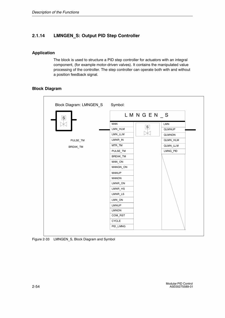
2.1.14 LMNGEN_S: Output PID Step Controller
Application
The block is used to structure a PID step controller for actuators with an integralcomponent, (for example motor-driven valves). It contains the manipulated valueprocessing of the controller. The step controller can operate both with and withouta position feedback signal.
Block Diagram
Symbol:
L M N G E N _ S
CYCLE
MAN_ON
MANGN_ON
QLMNUP
QLMNDN
MANDN
LMNR_ON
LMNR_HS
LMNR_LS
MANUP
LMNUP
LMNDN
LMN_ON
S
SMAN
LMN_HLM
LMN_LLM
LMNR_IN
BREAK_TM MTR_TM
QLMN_HLM
QLMN_LLM
LMN
COM_RST
PID_LMNG
LMNG_PID
Block Diagram: LMNGEN_S
PULSE_TM
PULSE_TM
BREAK_TM
Figure 2-33 LMNGEN_S, Block Diagram and Symbol
Description of the Functions
2-55Modular PID ControlA5E00275589-01
Functional Description
If a position feedback signal is available, the block can be used as a positioningcontroller. With the manual/automatic option, you can change over between themanipulated variable supplied by the PID algorithm and a manual value. You canenter a manual value as an absolute value or use the manual value generator toincrease and decrease the manual value. From the difference between themanipulated variable and the position feedback signal, the block generates thepulses for controlling the actuator via a three-step element and the pulsegenerator. By adapting the response threshold of the three-step element, theswitching frequency of the controller is reduced.
The block also functions without a position feedback signal. The I action of the PIDalgorithm and the position feedback signal are calculated in an integrator andcompared with the remaining PD actions. The difference is then applied to thethree-step element and the pulse generator that generates the pulses for the finalcontrol element. By adapting the response threshold of the three-step element, theswitching frequency of the controller is reduced.
The block is always used in conjunction with the PID algorithm block.
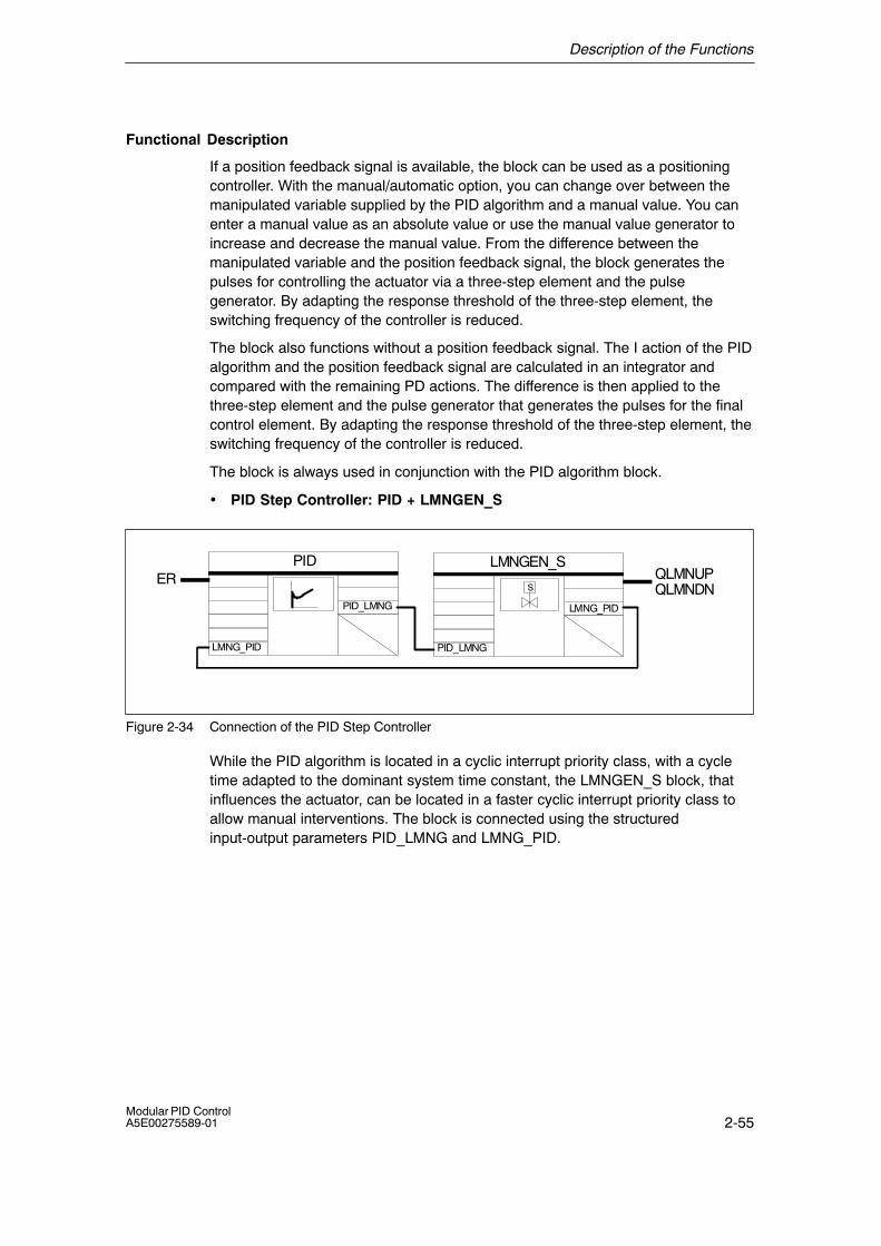
• PID Step Controller: PID + LMNGEN_S
LMNGEN_S
LMNG_PID
QLMNUPQLMNDN
PID
PID_LMNG
ERS
LMNG_PIDPID_LMNG
Figure 2-34 Connection of the PID Step Controller
While the PID algorithm is located in a cyclic interrupt priority class, with a cycletime adapted to the dominant system time constant, the LMNGEN_S block, thatinfluences the actuator, can be located in a faster cyclic interrupt priority class toallow manual interventions. The block is connected using the structuredinput-output parameters PID_LMNG and LMNG_PID.
Description of the Functions
2-56Modular PID Control
A5E00275589-01
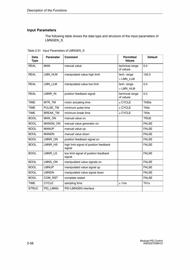
Input Parameters
The following table shows the data type and structure of the input parameters ofLMNGEN_S.
Table 2-31 Input Parameters of LMNGEN_S
DataType
Parameter Comment PermittedValues
Default
REAL MAN manual value technical rangeof values
0.0
REAL LMN_HLM manipulated value high limit tech. range
> LMN_LLM
100.0
REAL LMN_LLM manipulated value low limit tech. range
< LMN_HLM
0.0
REAL LMNR_IN position feedback signal technical rangeof values
0.0
TIME MTR_TM motor actuating time ≥ CYCLE T#30s
TIME PULSE_TM minimum pulse time ≥ CYCLE T#3s
TIME BREAK_TM minimum break time ≥ CYCLE T#3s
BOOL MAN_ON manual value on TRUE
BOOL MANGN_ON manual value generator on FALSE
BOOL MANUP manual value up FALSE
BOOL MANDN manual value down FALSE
BOOL LMNR_ON position feedback signal on FALSE
BOOL LMNR_HS high limit signal of position feedbacksignal
FALSE
BOOL LMNR_LS low limit signal of position feedbacksignal
FALSE
BOOL LMNS_ON manipulated value signals on FALSE
BOOL LMNUP manipulated value signal up FALSE
BOOL LMNDN manipulated value signal down FALSE
BOOL COM_RST complete restart FALSE
TIME CYCLE sampling time ≥ 1ms T#1s
STRUC PID_LMNG PID-LMNGEN interface
Description of the Functions
2-57Modular PID ControlA5E00275589-01
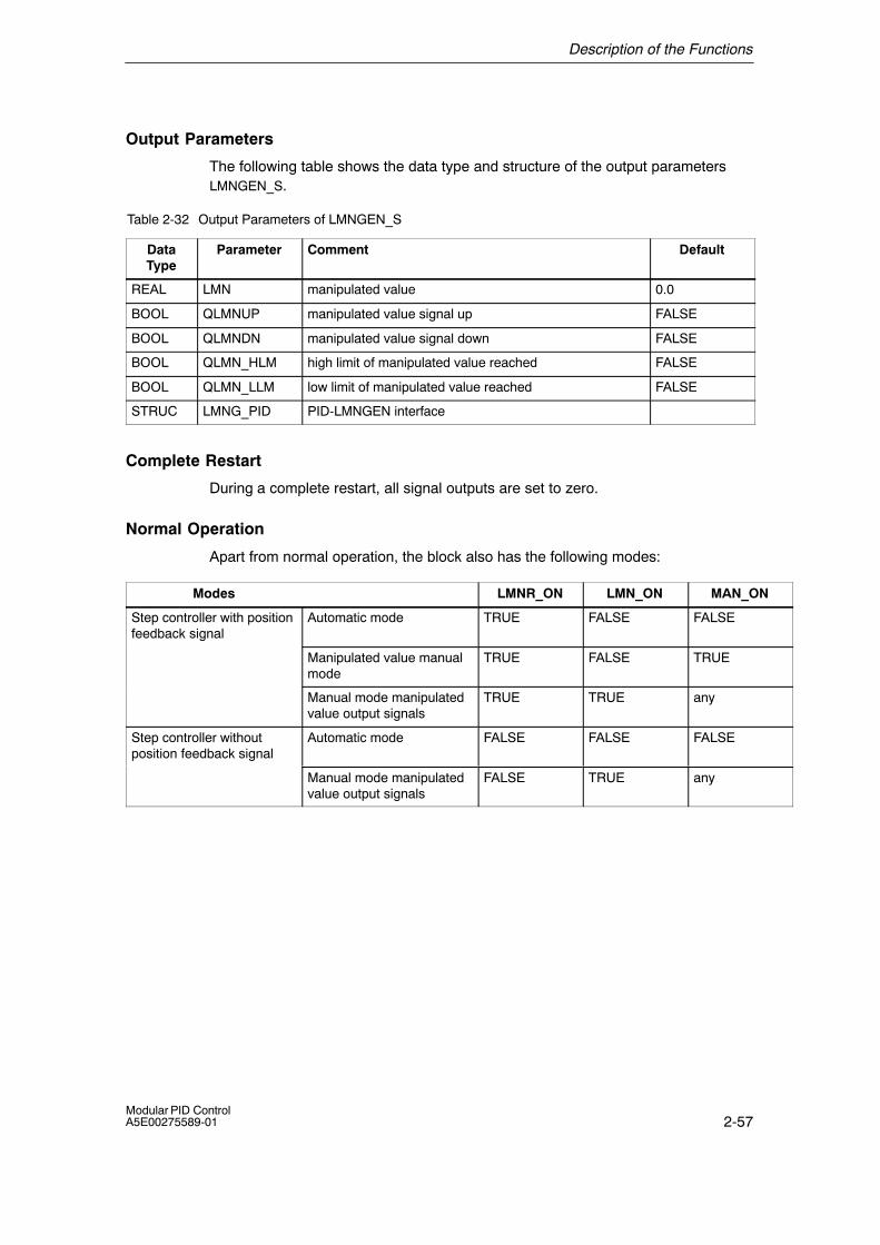
Output Parameters
The following table shows the data type and structure of the output parametersLMNGEN_S.
Table 2-32 Output Parameters of LMNGEN_S
DataType
Parameter Comment Default
REAL LMN manipulated value 0.0
BOOL QLMNUP manipulated value signal up FALSE
BOOL QLMNDN manipulated value signal down FALSE
BOOL QLMN_HLM high limit of manipulated value reached FALSE
BOOL QLMN_LLM low limit of manipulated value reached FALSE
STRUC LMNG_PID PID-LMNGEN interface
Complete Restart
During a complete restart, all signal outputs are set to zero.
Normal Operation
Apart from normal operation, the block also has the following modes:
Modes LMNR_ON LMN_ON MAN_ON
Step controller with positionfeedback signal
Automatic mode TRUE FALSE FALSE
Manipulated value manualmode
TRUE FALSE TRUE
Manual mode manipulatedvalue output signals
TRUE TRUE any
Step controller withoutposition feedback signal
Automatic mode FALSE FALSE FALSE
Manual mode manipulatedvalue output signals
FALSE TRUE any
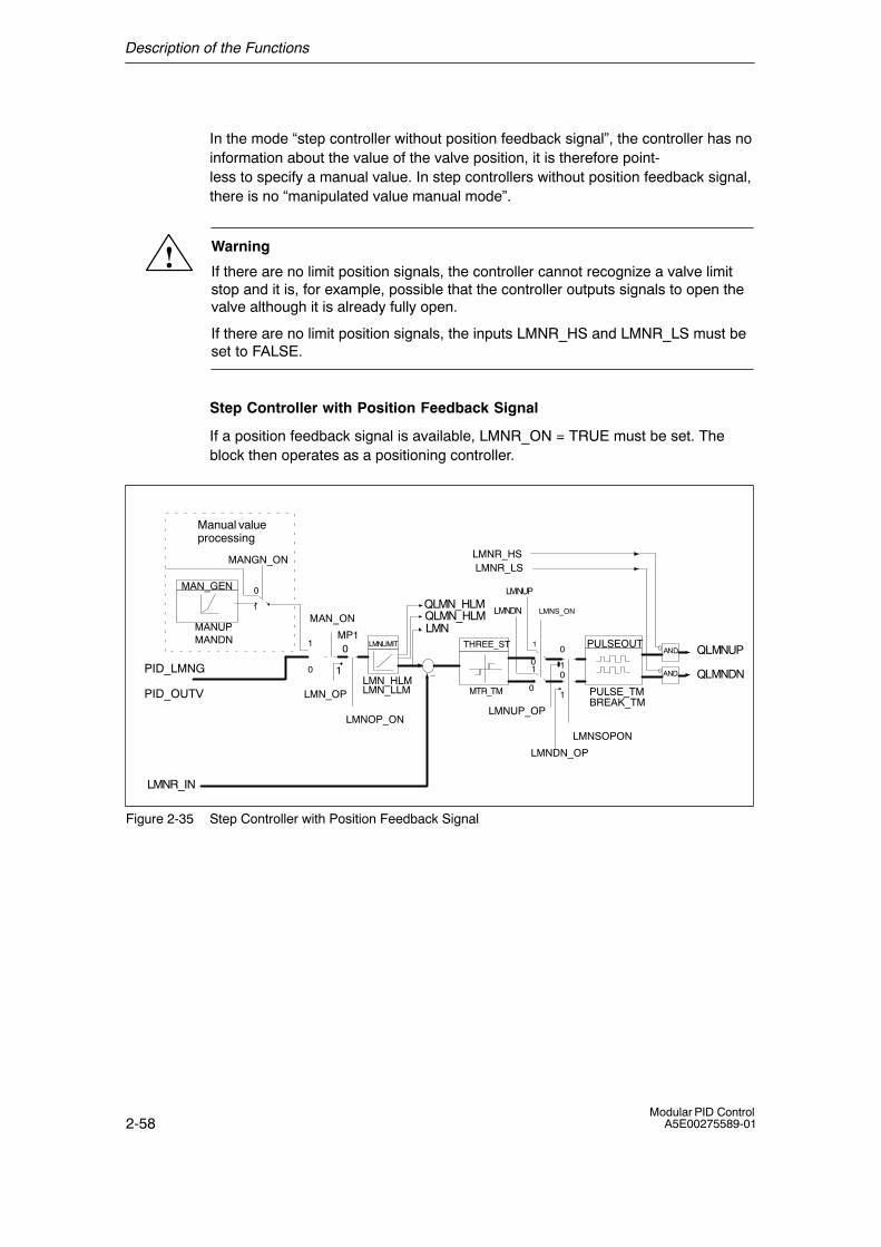
Description of the Functions
2-58Modular PID Control
A5E00275589-01
In the mode �step controller without position feedback signal�, the controller has noinformation about the value of the valve position, it is therefore point-less to specify a manual value. In step controllers without position feedback signal,there is no �manipulated value manual mode�.
! Warning
If there are no limit position signals, the controller cannot recognize a valve limitstop and it is, for example, possible that the controller outputs signals to open thevalve although it is already fully open.
If there are no limit position signals, the inputs LMNR_HS and LMNR_LS must beset to FALSE.
Step Controller with Position Feedback Signal
If a position feedback signal is available, LMNR_ON = TRUE must be set. Theblock then operates as a positioning controller.
LMNUP
LMNDN
1
MTR_TM
0
1
1
0
1
0
LMNLIMIT
QLMN_HLM
LMNQLMN_HLM
LMNR_IN
�
AND
AND
QLMNUP
QLMNDN
LMNOP_ONLMNUP_OP
LMNDN_OP
LMNSOPON
0
0
LMN_OP
1
1
01
0
LMNS_ONMAN_ON
PULSE_TM
MP1PULSEOUT
LMN_HLMLMN_LLM
THREE_ST
LMNR_HS
PID_LMNG
PID_OUTV
MANUPMANDN
MAN_GEN
Manual valueprocessing
MANGN_ONLMNR_LS
BREAK_TM
Figure 2-35 Step Controller with Position Feedback Signal
Description of the Functions
2-59Modular PID ControlA5E00275589-01
• Manipulated Value Manual Mode
In the positioning controller mode, you can switch over to the manual mode withthe switch MAN_ON and enter a manipulated value as an absolute value at inputMAN or use the manual value generator MAN_GEN.
If MANGN_ON = TRUE is set, the manipulated value can be increased ordecreased starting from its current value using the switches MANUP and MANDNwithin the limits LMN_HLM and LMN_LLM. The rate of change depends on thelimits as follows:
During the first 3 seconds after setting MANUP or MANDN:
dLMN/dt = (LMN_HLM � LMN_LLM) / 100 s
then: dLMN/dt = (LMN_HLM � LMN_LLM) / 10 s
If MANGN_ON = FALSE and MAN_ON = TRUE is set, the input value MAN isswitched through as the manipulated value.
• Manual Mode of the Manipulated Value Output Signals
If LMNS_ON = TRUE is set, the binary output signals can be influenced directly.The actuating signal outputs QLMNUP and QLMNDN are set with the switchesLMNUP and LMNDN. The minimum pulse time PULSE_TM and minimum breaktime BREAK_TM are taken into account. If one of the limit position switchesLMNR_HS or LMNR_LS is set, the corresponding output signal QLMNUP orQLMNDN is disabled.
• Automatic Mode
The manipulated value from the PID algorithm PID_LMNG.PID_OUTV is limited tothe selectable values LMN_HLM and LMN_LLM. The difference between themanipulated value and position feedback signal is switched to a three-step elementwith hysteresis. The off threshold is calculated from the motor actuating time. Toreduce switching frequency, the on threshold is adapted. The pulse generatorPULSEOUT ensures that the minimum pulse and break times are kept to. If one ofthe limit position switches LMNR_HS or LMNR_LS is set, the corresponding outputsignal QLMNUP or QLMNDN is disabled.

Description of the Functions
2-60Modular PID Control
A5E00275589-01
Step Controller without Position Feedback Signal
LMN_ON
LMNUP
LMNDN
PULSE_TM,BREAK_TM
PID_LMNG.PID_OUTV
MTR_TM
INT
THREE_ST PULSEOUT
1
0
1
0
LMNLIMIT
100.0,�100.0PID_LMNG.
PID_SCTR
�
AND
AND
LMNR_HSLMNR_LS
100.0 0.0
+
1/MTR_TM
01
1 0�100.0 0.0
�
OR
0.0 1
0
INT LMNLIMIT
100.0,0.0
LMNRS_ONLMNRSVAL
LMNR_SIM
Simulation of the position feedback signal LMNRS_ON
QLMNUPQLMNDN
0.0 1
0
LMNUP_OP
LMNDN_OP LMNSOPON
0
01
x
Figure 2-36 Step Controller without Position Feedback Signal
If no position feedback signal is available, LMNR_ON = FALSE is set.
• Manual Mode for Manipulated Value Output Signals
If LMNS_ON = TRUE is set, the binary output signals can be influenced directly.The actuating signal outputs QLMNUP and QLMNDN are set with the switchesLMNUP and LMNDN. The minimum pulse time PULSE_TM and minimum breaktime BREAK_TM are taken into account. If one of the limit position switchesLMNR_HS or LMNR_LS is set, the corresponding output signal QLMNUP orQLMNDN is disabled.
• Automatic Mode
The difference of the I action of the PID algorithm and an internal position feedbacksignal is integrated in the integrator INT. The input of the integrator is the differencebetween 100.0 / 0.0 /. �100.0 (depending on the state of the output signalsQLMNUP and QLMNDN) relative to the motor actuating time MTR_TM and theerror signal multiplied by the gain relative to the reset time TI of the PID algorithm(PID_LMNG.PID_SCTR). The output of the integrator forms the feedback signalthat is compared with the remaining PD action of the PID algorithm(PID.LMNG.PID_OUTV). The difference is switched to a three-step element withhysteresis. The off threshold is calculated from the motor actuating time.
Description of the Functions
2-61Modular PID ControlA5E00275589-01
To reduce switching frequency, the on threshold is adapted. The pulse generatorPULSEOUT ensures that the minimum pulse and break times are kept to. If one ofthe limit position switches LMNR_HS or LMNR_LS is set, the corresponding outputsignal QLMNUP or QLMNDN is disabled.
Simulation of the Position Feedback Signal
The position feedback signal is simulated by an integrator with the motor actuatingtime MTR_TM as reset time. Changing the parameter LMNRS_ON from FALSE toTRUE starts the simulation with the initial value LMNRSVAL. If LMNRS_ON is setto FALSE, then the initial value LMNRSVAL is output for the parameterLMNR_SIM. The parameters LMNRS_ON, LMNRSVAL and LMNR_SIM arelocated in the static variable area. They are supplied with values by theconfiguration tool. If LMNR_HS = TRUE, the upwards integration is disabled. IfLMNR_LS = TRUE, the downwards integration is disabled.
!Warning
The position feedback signal is only simulated. It does not necessarily correspondto the real position feedback signal of the final control element.
The PID process identification function of the configuration tool requires theposition feedback signal as an input variable.
If a real position feedback signal exists, it should be used.
Block-Internal Limits
No values are limited internally in the block; the parameters are not checked.

Description of the Functions
2-62Modular PID Control
A5E00275589-01
Influencing the Manipulated Value with the configuration tool
LMN Display and Setting in the Loop Monitor
Die configuration tool has its own interface to the LMNGEN_S block. It is thereforealways possible to interrupt the manipulated variable branch when working on aprogramming device or PC and to set your own manipulated values (Figure 2-37).
��������
�����������������
������
������ �
LMNUPLMNDN
��� ����
����
LMNUP_OPLMNDN_OP
MP1
LMN_OP
��� ����
LMNS_ON
Figure 2-37 Interventions in the Manipulated Value Branch Using the configuration tool
The loop monitor has a field labeled �manipulated value�. Here, in the upper field(�Controller:�), the manipulated value currently applied to measuring point MP1 isdisplayed. In the field below (�PG:�), you can set the parameter LMN_OP.
Switching over to Manual Manipulated Value with the configuration tool
If the switch in the configuration tool is set to �PG: �, the switching signal of thestructure switch LMNOP_ON is set to TRUE in the controller FB and LMN_OP isswitched through to the manipulated value LMN.
If the rate of change limit LMN_ROC is activated in the manipulated variablebranch , it is possible to switch between �PG: � and �Controller: � without causingany sudden change. The value to which the manipulated variable switches back(MP1) can be seen in the �Controller: � display field of the loop monitor. LMN thenreturns to this value at the rate of change set at LMN_ROC.
If the switch �Controller:/PG: � in the manipulated values field is set to �PG: �, theparameter LMNSOPON = TRUE is set and the actuating signal outputs can becontrolled with the parameters LMNUP_OP (up) or LMNDN_OP (down) in the loopmonitor. This applies to a step controller with or without position feedbacksignal.These interventions only affect the process after you transfer them to theprogrammable controller by clicking the �Send� button in the loop monitor.Theparameters LMNOP_ON, LMN_OP, MP1, LMNSOPON, LMNUP_OP andLMNDN_OP are static variables and are not available as input/output parametersfor the block. The parameters should not be connected and should only be usedand monitored with the configuration tool.
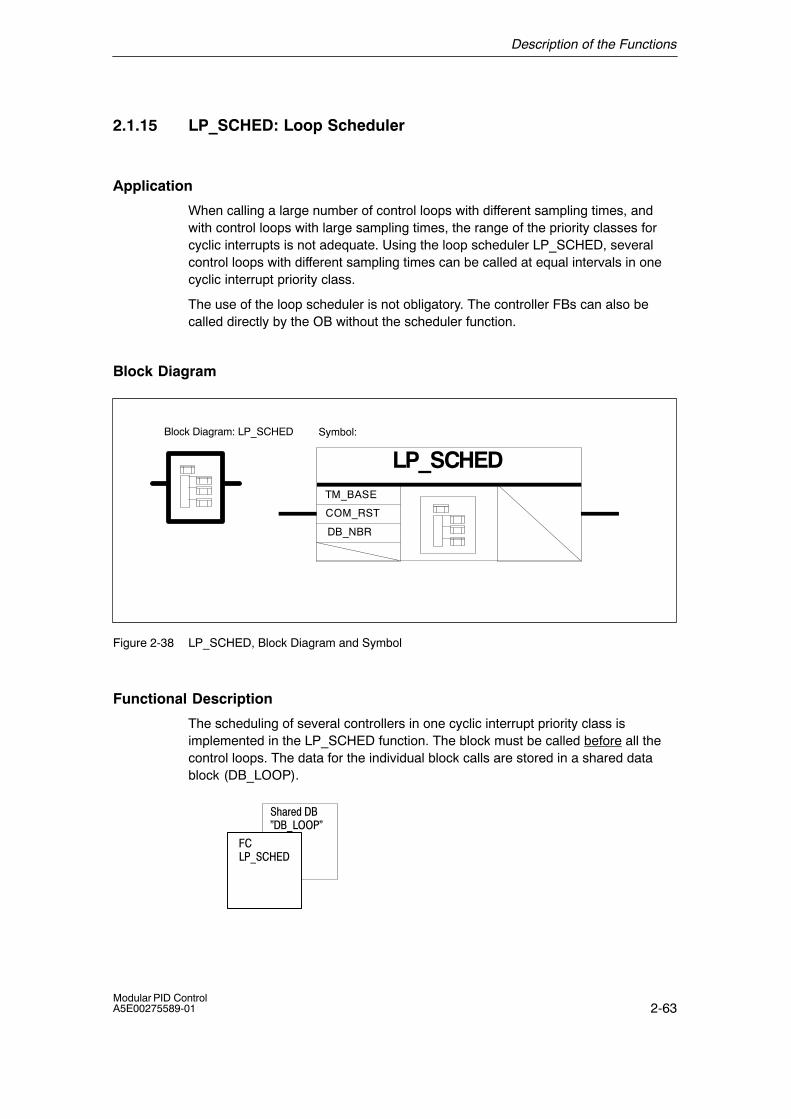
Description of the Functions
2-63Modular PID ControlA5E00275589-01
2.1.15 LP_SCHED: Loop Scheduler
Application
When calling a large number of control loops with different sampling times, andwith control loops with large sampling times, the range of the priority classes forcyclic interrupts is not adequate. Using the loop scheduler LP_SCHED, severalcontrol loops with different sampling times can be called at equal intervals in onecyclic interrupt priority class.
The use of the loop scheduler is not obligatory. The controller FBs can also becalled directly by the OB without the scheduler function.
Block Diagram
Symbol:
LP_SCHED
COM_RST
TM_BASE
DB_NBR
Block Diagram: LP_SCHED
Figure 2-38 LP_SCHED, Block Diagram and Symbol
Functional Description
The scheduling of several controllers in one cyclic interrupt priority class isimplemented in the LP_SCHED function. The block must be called before all thecontrol loops. The data for the individual block calls are stored in a shared datablock (DB_LOOP).
���� ����
�����������������
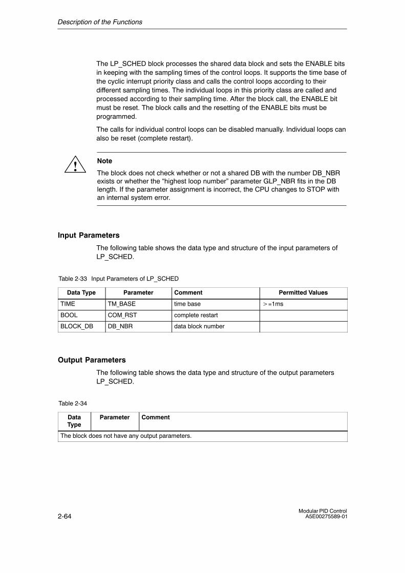
Description of the Functions
2-64Modular PID Control
A5E00275589-01
The LP_SCHED block processes the shared data block and sets the ENABLE bitsin keeping with the sampling times of the control loops. It supports the time base ofthe cyclic interrupt priority class and calls the control loops according to theirdifferent sampling times. The individual loops in this priority class are called andprocessed according to their sampling time. After the block call, the ENABLE bitmust be reset. The block calls and the resetting of the ENABLE bits must beprogrammed.
The calls for individual control loops can be disabled manually. Individual loops canalso be reset (complete restart).
! Note
The block does not check whether or not a shared DB with the number DB_NBRexists or whether the �highest loop number� parameter GLP_NBR fits in the DBlength. If the parameter assignment is incorrect, the CPU changes to STOP withan internal system error.
Input Parameters
The following table shows the data type and structure of the input parameters ofLP_SCHED.
Table 2-33 Input Parameters of LP_SCHED
Data Type Parameter Comment Permitted Values
TIME TM_BASE time base �=1ms
BOOL COM_RST complete restart
BLOCK_DB DB_NBR data block number
Output Parameters
The following table shows the data type and structure of the output parametersLP_SCHED.
Table 2-34
DataType
Parameter Comment
The block does not have any output parameters.
Description of the Functions
2-65Modular PID ControlA5E00275589-01
Neustart
Bei COM_RST = TRUE werden folgende Vorbelegungen eingestellt:
Aktuelle Regelkreisnummer: ALP_NBR = 0
Die Aufrufdaten aller Regelkreise bei GLP_NBR werden wie folgt vorbelegt:
Freigabe: ENABLE = NOT MAN_DIS
Abtastzeit: CYCLE = GV(MAN_CYC)
Neustart: COM_RST = TRUE
Lokale Aufrufnummer: ILP_COU = 0
GV(MAN_CYC) = MAN_CYC wird gerundet auf ein ganzzahliges Vielfaches von TM_BASE*GLP_NBR
Description of the Functions
2-66Modular PID Control
A5E00275589-01
Shared Data Block �DB_LOOP�
The following table shows the shared data block DB_LOOP for the controller calls.
Table 2-35
DataType
Parameter Comment PermittedValues
Default
INT GLP_NBR greatest loop number 1 � 256 2
INT ALP_NBR actual loop number 0 � 256 0
TIME LOOP_DAT[1].
MAN_CYC
loop data [1] manual samplingtime
�=1ms T#1s
BOOL LOOP_DAT[1].
MAN_DIS
loop data [1] manual loop disable FALSE
BOOL LOOP_DAT[1].
MAN_CRST
loop data [1] manual completerestart
FALSE
BOOL LOOP_DAT[1].
ENABLE
loop data [1] enable loop FALSE
BOOL LOOP_DAT[1].
COM_RST
loop data [1] complete restart FALSE
INT LOOP_DAT[1].ILP_COU
loop data [1] internal loop counter 0
TIME LOOP_DAT[1].
CYCLE
loop data [1] sampling time �=1ms T#1s
Description of the Functions
2-67Modular PID ControlA5E00275589-01
Calling a Control Loop Using LP_SCHED
The LP_SCHED function is integrated in the call strategy of the CPU using threeinput parameters. The time base of the cyclic interrupt class is specified at theTM_BASE input. The control loops are called using a conditional block call in onecyclic interrupt class (for example OB35) and the ENABLE bits are queried in theshared data block.
If the call is made at the complete restart level, the input COM_RST = TRUE isset. This call must be reset to FALSE in the cyclic interrupt class. The shared datablock (Table 2-35) with the time data for the control loops in the cyclic interruptclass is assigned using the input parameter DB_NBR.
Programming a Control Loop Call (Shared DB)
The loop scheduler must be programmed without the support of the configurationtool.
The data block (DB_LOOP) contains both a parameter for the total number ofcontrol loops to be processed in the cyclic interrupt class (a maximum of 256) anda parameter to indicate the control loop currently being processed, as follows:
GLP_NBR Highest control loop numberALP_NBR Number of the control loop being processed in the cycle
The number of each control loop is decided by the position of its call in thesequence of entries in the DB.
The call data of the individual control loops are in structured form in theLOOP_DAT field. If you want to add control loops, the field length of LOOP_DATmust be adapted by modifying the ARRAY data type in the declaration view. With,for example 10 loops, you would enter ARRAY[1..10]. You must also adapt theparameter GLP_NBR in the data view. It must never be higher than the fieldlength.
The parameters COM_RST and CYCLE must be linked to the corresponding inputparameters of the FB belonging to the called control loop. This connection must beprogrammed by the user. If the ENABLE parameter is set, the correspondingcontrol loop will be called. After the controller has been called, the ENABLE bitmust be reset. The user must program the conditional controller call and theENABLE bit reset.
Using the parameters MAN_CYC / MAN_DIS / MAN_CRST that can be setmanually, you can decide whether or not a control loop is called. You can changethese calls online (in other words during operation) as long as you only overwriteparameters and do not regenerate the entire DB. The meaning of the parametersis as follows:
MAN_CYC Sampling time of the corresponding controller (rounded up to a whole multiple of TM_BASE * GLP_NBR in CYCLE).
MAN_DIS Disable the controller call.
MAN_CRST Complete restart for the controller.
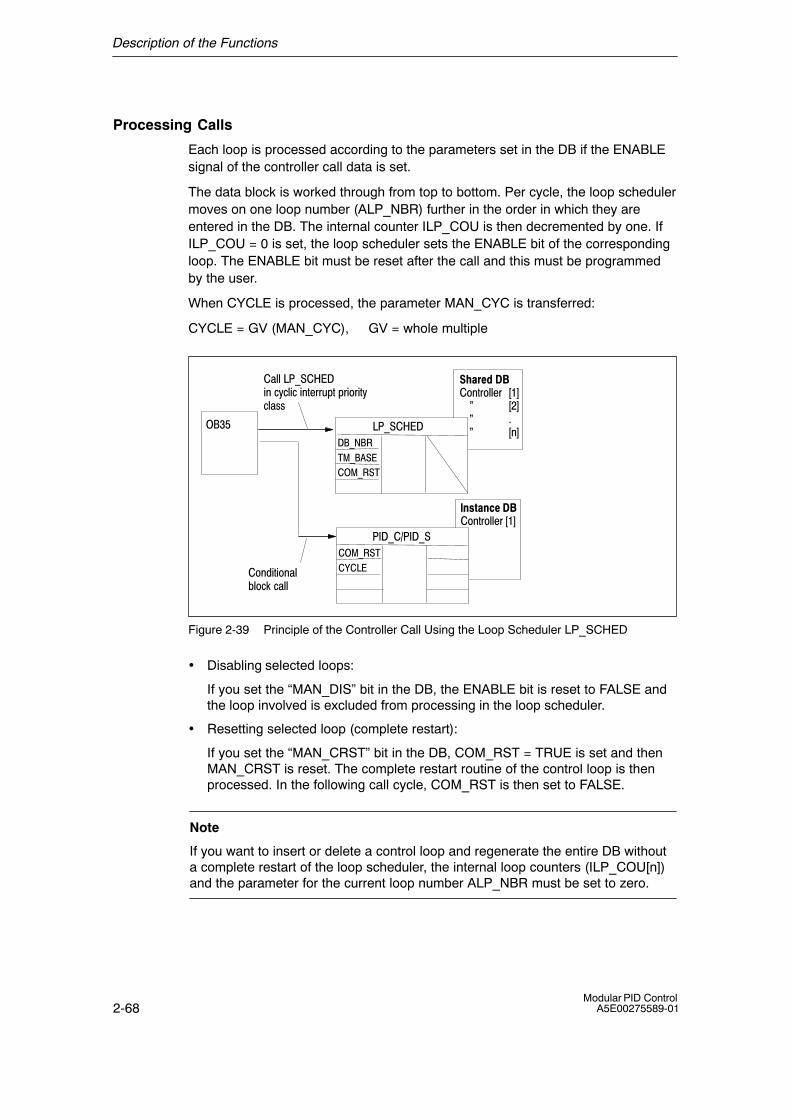
Description of the Functions
2-68Modular PID Control
A5E00275589-01
Processing Calls
Each loop is processed according to the parameters set in the DB if the ENABLEsignal of the controller call data is set.
The data block is worked through from top to bottom. Per cycle, the loop schedulermoves on one loop number (ALP_NBR) further in the order in which they areentered in the DB. The internal counter ILP_COU is then decremented by one. IfILP_COU = 0 is set, the loop scheduler sets the ENABLE bit of the correspondingloop. The ENABLE bit must be reset after the call and this must be programmedby the user.
When CYCLE is processed, the parameter MAN_CYC is transferred:
CYCLE = GV (MAN_CYC), GV = whole multiple
���������
�� !��""���#�$
��� ���
�� !��""�� #�$�������� #%$����� &����� # $
��'(
������
����� �
����� �
��� ����
����� �
�)���
�����*����
�� �+!+� �","�-.�-�""
��""���� ����+ �-/-"+-�+ !���01!�1�+��+!/-"�22
Figure 2-39 Principle of the Controller Call Using the Loop Scheduler LP_SCHED
• Disabling selected loops:
If you set the �MAN_DIS� bit in the DB, the ENABLE bit is reset to FALSE andthe loop involved is excluded from processing in the loop scheduler.
• Resetting selected loop (complete restart):
If you set the �MAN_CRST� bit in the DB, COM_RST = TRUE is set and thenMAN_CRST is reset. The complete restart routine of the control loop is thenprocessed. In the following call cycle, COM_RST is then set to FALSE.
Note
If you want to insert or delete a control loop and regenerate the entire DB withouta complete restart of the loop scheduler, the internal loop counters (ILP_COU[n])and the parameter for the current loop number ALP_NBR must be set to zero.

Description of the Functions
2-69Modular PID ControlA5E00275589-01
Conditions for Calling a Loop With LP_SCHED
To ensure that the intervals between the calls of a particular controller remainconstant and to spread the load on the CPU, only one control loop can beprocessed per time base unit of the cyclic interrupt class. When you assign thesampling times MAN_CYC, remember the following conditions with respect to thetime base (TM_BASE):
• The processing times of the individual loops must be shorter than the time base(TM_BASE) of the cyclic interrupt class.
• The sampling time of a control loop (MAN_CYC) must be a whole multiple (GV)of the product of the time base and number of controllers to be processed(GLP_NBR):
MAN_CYC = GV (TM_BASE � GLP_NBR).
Example of Loop Scheduling
The following example illustrates the sequence of calls of four loops in one cyclicinterrupt class (Figure 2-40). Only one loop is processed per time base unit. Thesequence in which the loops are called and with it the time displacement (TD1 toTD5) result from the sequence of the call data within the shared data block.
ÇÇ
�� !��"�"��1��3 �)���#�$�4��������� ��5�6�������7� ���4��5������
�� !��"�"��1�%3 �)���#%$�4�'������� ��5�6�������7� ���4���5������
�� !��"�"��1�'3 �)���#'$�4��������� ��5�6�������7� ���4�%�5������
�� !��"�"��1�83 �)���#8$�4�%������� ��5�6�������7� ���4�'�5������
ÉÉ
����� �
ÇÇ
ÉÉÉÉ
ÉÉ
ÉÉ
!
����� � !+9��,�2���:�!���-/-"+-�+ !���01!�-"�22
6������ �+;��2!�"��1� 09,���������4�8�
�)���#�$� &&$ 2�91"+ ;�!+9���:�!���-� !��""���#�$�!��#8$
���&&&��8 !+9���+21"�-�9� !���!��8
Figure 2-40 Call Sequence of Four Loops Called at Different Intervals
Block-Internal Limits
The values of the parameters are not limited in the block; the parameters are notchecked.

Description of the Functions
2-70Modular PID Control
A5E00275589-01
2.1.16 NONLIN: Non-Linear Static Function
Application
With NONLIN, the input value, for example a measured value from athermoelement, can be adapted using a selectable function.
Block Diagram
: NONLIN Symbol:
NONLININV OUTV
DB_NBR
TRACK
DF_OUTV
DFOUT_ON
COM_RST
Block Diagram
Figure 2-41 NONLIN, Block Diagram and Symbol
Functional Description
The points of the function are stored in a shared data block. NONLIN assigns thecorresponding output value to the current input value from the function. If the inputvalue is lower than the value at point 0, the value is extrapolated with the slopebetween points 0 and 1. If the value is higher than the value of the last point, sowird mit der Steigerung des letzten Stützpunktpaares extrapoliert. For the block tosupply a feasible result, the values of the points must have a strictly monotonousrising slope.
Using control inputs, a selected value or the input variable itself can be outputdirectly as the output variable.
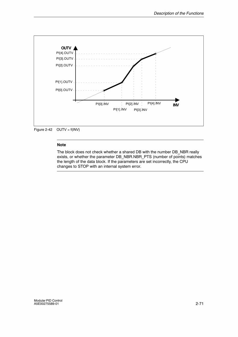
Description of the Functions
2-71Modular PID ControlA5E00275589-01
OUTV
INVPI[1].INV
PI[2].INV
PI[3].INV
PI[0].INV PI[4].INV
PI[0].OUTV
PI[1].OUTV
PI[2].OUTV
PI[3].OUTV
PI[4].OUTV
Figure 2-42 OUTV = f(INV)
Note
The block does not check whether a shared DB with the number DB_NBR reallyexists, or whether the parameter DB_NBR.NBR_PTS (number of points) matchesthe length of the data block. If the parameters are set incorrectly, the CPUchanges to STOP with an internal system error.
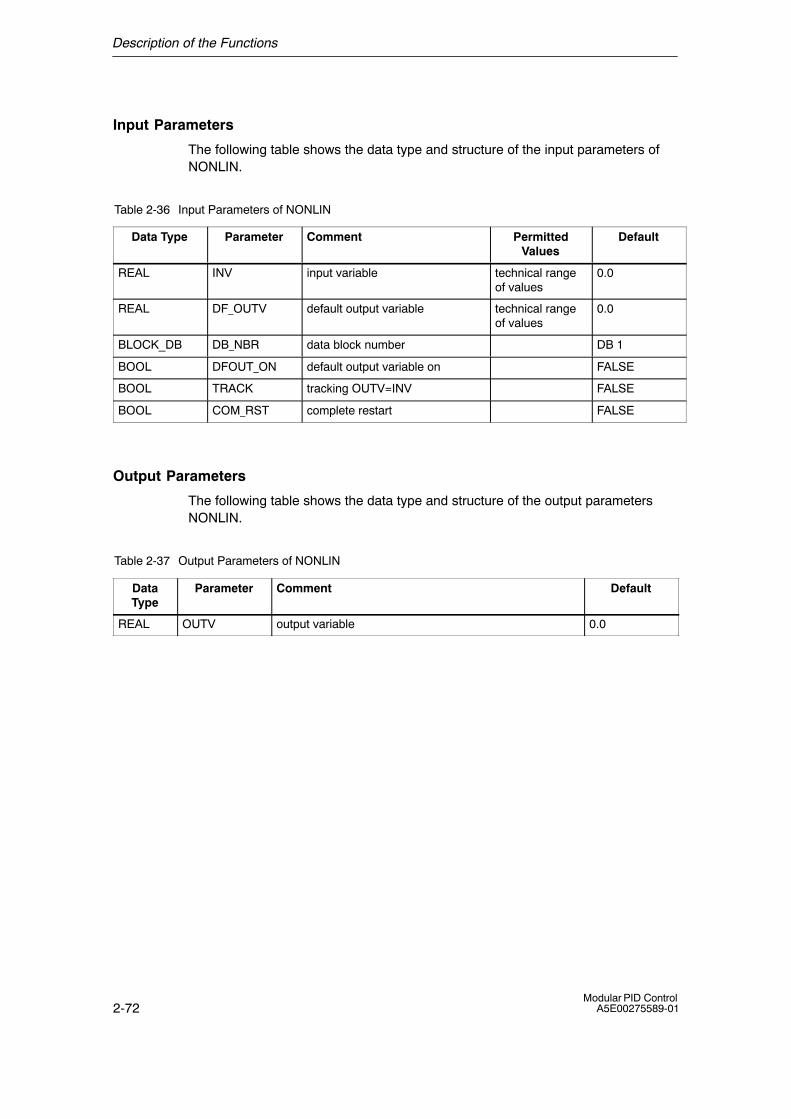
Description of the Functions
2-72Modular PID Control
A5E00275589-01
Input Parameters
The following table shows the data type and structure of the input parameters ofNONLIN.
Table 2-36 Input Parameters of NONLIN
Data Type Parameter Comment PermittedValues
Default
REAL INV input variable technical rangeof values
0.0
REAL DF_OUTV default output variable technical rangeof values
0.0
BLOCK_DB DB_NBR data block number DB 1
BOOL DFOUT_ON default output variable on FALSE
BOOL TRACK tracking OUTV=INV FALSE
BOOL COM_RST complete restart FALSE
Output Parameters
The following table shows the data type and structure of the output parametersNONLIN.
Table 2-37 Output Parameters of NONLIN
DataType
Parameter Comment Default
REAL OUTV output variable 0.0

Description of the Functions
2-73Modular PID ControlA5E00275589-01
Shared Data Block DB_NBR
The following table shows the data type and Parameter von DB_NBR (default with5 curve points).
DataType
Parameter Comment Permitted Values Default
INT DB_NBR.NBR_PTS highest coordinate 1 � 255 4
REAL DB_NBR.PI[0].OUTV output variable [0], point 0 technical range of values 0.0
REAL DB_NBR.PI[0].INV input variable [0], point 0 technical range of values 0.0
REAL DB_NBR.PI[1].OUTV output variable [1], point 1 technical range of values 0.0
REAL DB_NBR.PI[1].INV input variable [1], point 1 technical range of values 0.0
REAL DB_NBR.PI[2].OUTV output variable [2], point 2 technical range of values 0.0
REAL DB_NBR.PI[2].INV input variable [2], point 2 technical range of values 0.0
REAL DB_NBR.PI[3].INV input variable [3], point 3 technical range of values 0.0
REAL DB_NBR.PI[3].OUTV output variable [3], point 3 technical range of values 0.0
REAL DB_NBR.PI[4].OUTV output variable [4], point 4 technical range of values 0.0
REAL DB_NBR.PI[4].INV input variable [4], point 4 technical range of values 0.0
Complete Restart
During a complete restart OUTV = 0.0 is output.
If DFOUT_ON=TRUE then DF_OUTV is output.
Normal Operation
In normal operation, wird durch Interpolation am aktuellen Stützpunktpaar derAusgangswert berechnet.
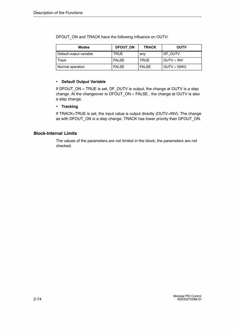
Description of the Functions
2-74Modular PID Control
A5E00275589-01
DFOUT_ON and TRACK have the following influence on OUTV:
Modes DFOUT_ON TRACK OUTV
Default output variable TRUE any DF_OUTV
Track FALSE TRUE OUTV = INV
Normal operation FALSE FALSE OUTV = f(INV)
• Default Output Variable
If DFOUT_ON = TRUE is set, DF_OUTV is output, the change at OUTV is a stepchange. At the changeover to DFOUT_ON = FALSE , the change at OUTV is alsoa step change.
• Tracking
If TRACK=TRUE is set, the input value is output directly (OUTV=INV). The changeas with DFOUT_ON is a step change. TRACK has lower priority than DFOUT_ON.
Block-Internal Limits
The values of the parameters are not limited in the block; the parameters are notchecked.
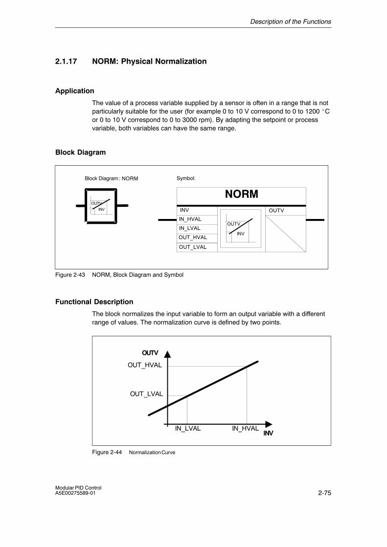
Description of the Functions
2-75Modular PID ControlA5E00275589-01
2.1.17 NORM: Physical Normalization
Application
The value of a process variable supplied by a sensor is often in a range that is notparticularly suitable for the user (for example 0 to 10 V correspond to 0 to 1200 �Cor 0 to 10 V correspond to 0 to 3000 rpm). By adapting the setpoint or processvariable, both variables can have the same range.
Block Diagram
: NORM Symbol:
NORMINV OUTV
IN_LVAL
OUT_LVAL
IN_HVAL
OUT_HVAL
OUTV
INV
OUTV
INV
Block Diagram
Figure 2-43 NORM, Block Diagram and Symbol
Functional Description
The block normalizes the input variable to form an output variable with a differentrange of values. The normalization curve is defined by two points.
OUTV
INV
OUT_HVAL
OUT_LVAL
IN_LVAL IN_HVAL
Figure 2-44 Normalization Curve
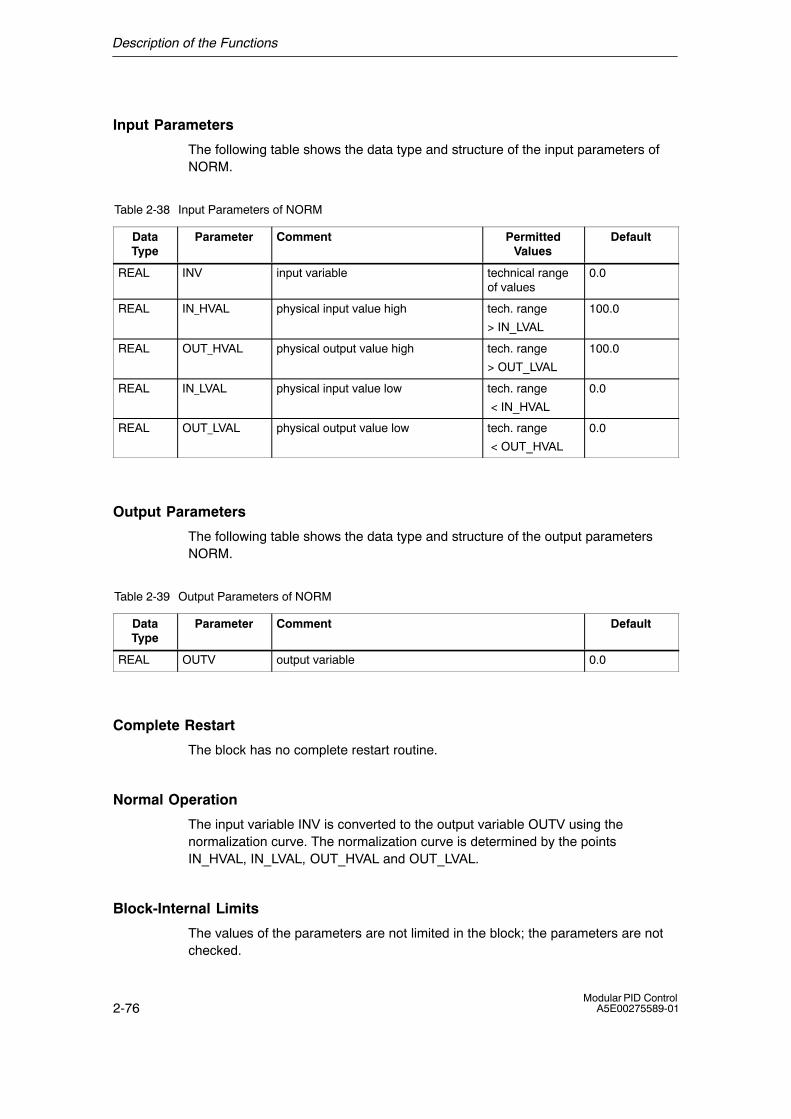
Description of the Functions
2-76Modular PID Control
A5E00275589-01
Input Parameters
The following table shows the data type and structure of the input parameters ofNORM.
Table 2-38 Input Parameters of NORM
DataType
Parameter Comment PermittedValues
Default
REAL INV input variable technical rangeof values
0.0
REAL IN_HVAL physical input value high tech. range
> IN_LVAL
100.0
REAL OUT_HVAL physical output value high tech. range
> OUT_LVAL
100.0
REAL IN_LVAL physical input value low tech. range
< IN_HVAL
0.0
REAL OUT_LVAL physical output value low tech. range
< OUT_HVAL
0.0
Output Parameters
The following table shows the data type and structure of the output parametersNORM.
Table 2-39 Output Parameters of NORM
DataType
Parameter Comment Default
REAL OUTV output variable 0.0
Complete Restart
The block has no complete restart routine.
Normal Operation
The input variable INV is converted to the output variable OUTV using thenormalization curve. The normalization curve is determined by the pointsIN_HVAL, IN_LVAL, OUT_HVAL and OUT_LVAL.
Block-Internal Limits
The values of the parameters are not limited in the block; the parameters are notchecked.
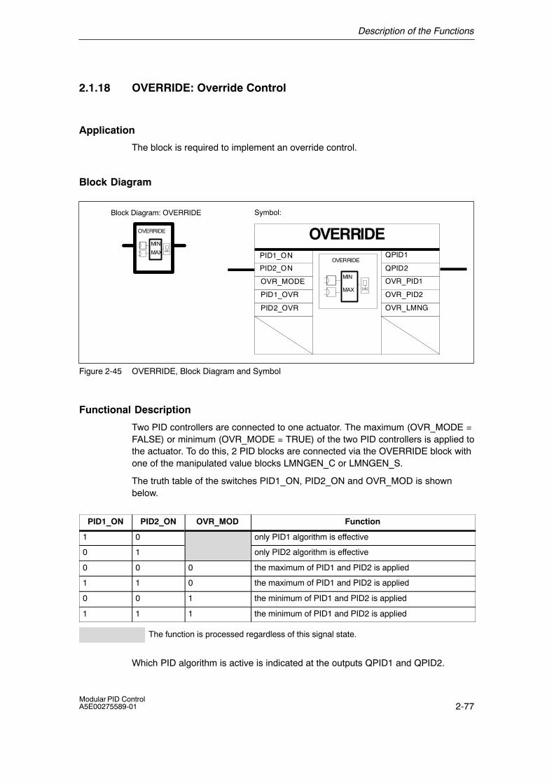
Description of the Functions
2-77Modular PID ControlA5E00275589-01
2.1.18 OVERRIDE: Override Control
Application
The block is required to implement an override control.
Block Diagram
Symbol:
OVERRIDEOVERRIDE
OVERRIDE
MIN
MAX
MIN
MAX
PID1_ON
PID2_ON
PID1_OVR
QPID1
QPID2
PID2_OVR
OVR_MODE OVR_PID1
OVR_PID2
OVR_LMNG
Block Diagram: OVERRIDE
Figure 2-45 OVERRIDE, Block Diagram and Symbol
Functional Description
Two PID controllers are connected to one actuator. The maximum (OVR_MODE =FALSE) or minimum (OVR_MODE = TRUE) of the two PID controllers is applied tothe actuator. To do this, 2 PID blocks are connected via the OVERRIDE block withone of the manipulated value blocks LMNGEN_C or LMNGEN_S.
The truth table of the switches PID1_ON, PID2_ON and OVR_MOD is shownbelow.
PID1_ON PID2_ON OVR_MOD Function
1 0 only PID1 algorithm is effective
0 1 only PID2 algorithm is effective
0 0 0 the maximum of PID1 and PID2 is applied
1 1 0 the maximum of PID1 and PID2 is applied
0 0 1 the minimum of PID1 and PID2 is applied
1 1 1 the minimum of PID1 and PID2 is applied
The function is processed regardless of this signal state.
Which PID algorithm is active is indicated at the outputs QPID1 and QPID2.
Description of the Functions
2-78Modular PID Control
A5E00275589-01
Input Parameters
The following table shows the data type and structure of the input parameters ofOVERRIDE.
Table 2-40 Input Parameters of OVERRIDE
DataType
Parameter Comment PermittedValues
Default
BOOL PID1_ON PID controller 1 on FALSE
BOOL PID2_ON PID controller 2 on FALSE
BOOL OVR_MODE override mode FALSE = maximum, TRUE= minimum
FALSE
STRUC PID1_OVR PID-LMNGEN interface
STRUC PID2_OVR PID-LMNGEN interface
Output Parameters
The following table shows the data type and structure of the output parametersOVERRIDE.
Table 2-41 Output Parameters of OVERRIDE
DataType
Parameter Comment Default
BOOL QPID1 PID controller 1active
BOOL QPID2 PID controller 2active
STRUC OVR_LMNG PID-LMNGEN interface
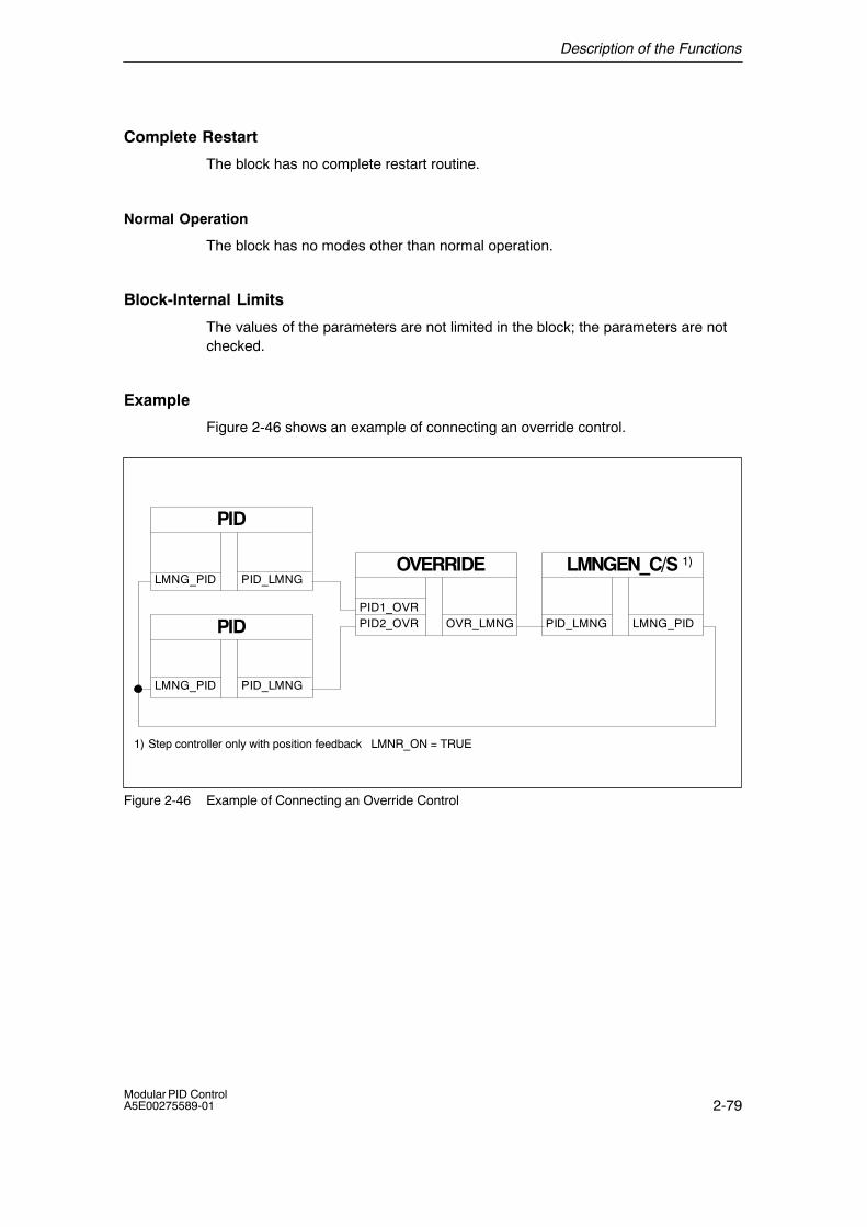
Description of the Functions
2-79Modular PID ControlA5E00275589-01
Complete Restart
The block has no complete restart routine.
Normal Operation
The block has no modes other than normal operation.
Block-Internal Limits
The values of the parameters are not limited in the block; the parameters are notchecked.
Example
Figure 2-46 shows an example of connecting an override control.
PID
PID_LMNGLMNG_PIDOVERRIDE
OVR_LMNGPID2_OVR
LMNGEN_C/S
LMNG_PIDPID_LMNGPID1_OVR
1) Step controller only with position feedback LMNR_ON = TRUE
1)
PID
PID_LMNGLMNG_PID
Figure 2-46 Example of Connecting an Override Control
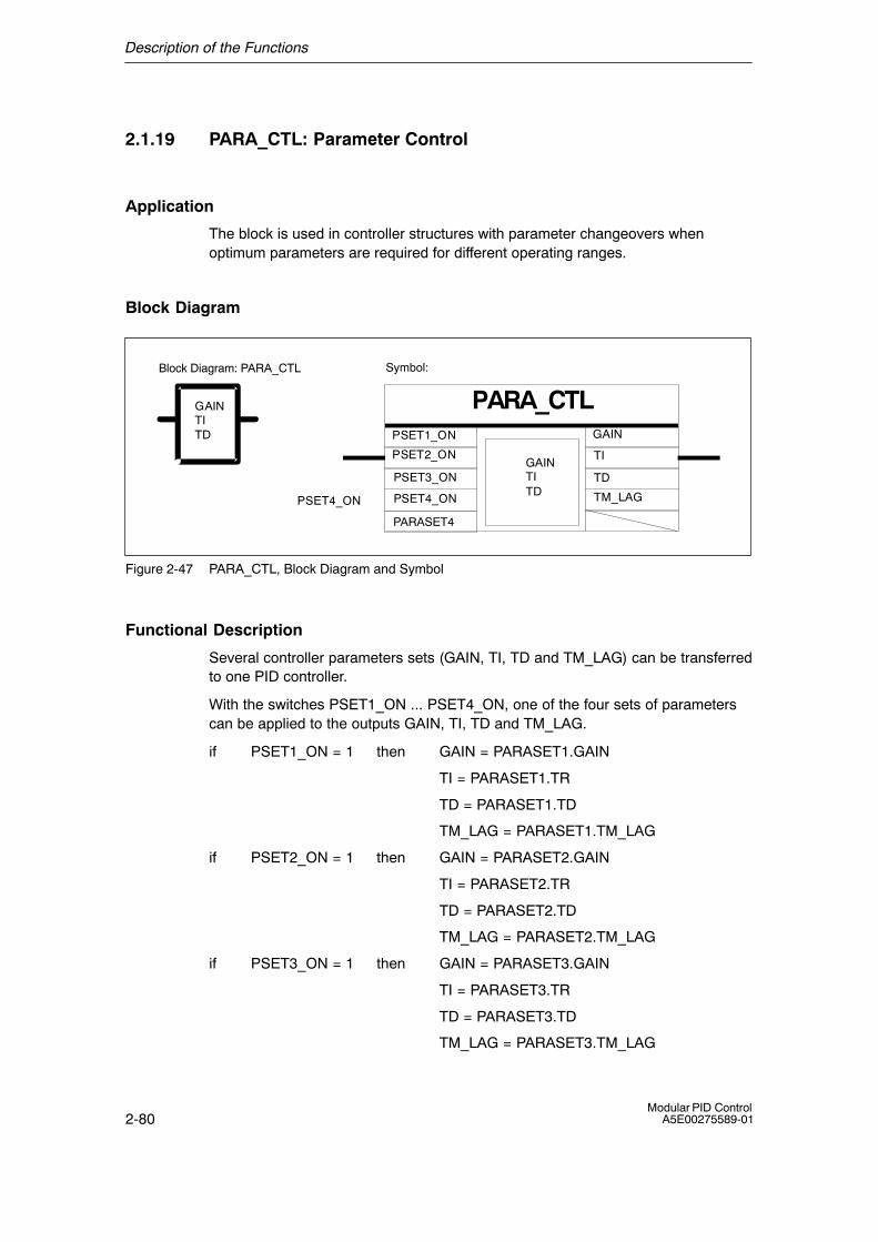
Description of the Functions
2-80Modular PID Control
A5E00275589-01
2.1.19 PARA_CTL: Parameter Control
Application
The block is used in controller structures with parameter changeovers whenoptimum parameters are required for different operating ranges.
Block Diagram
Symbol:
PARA_CTLGAINTITD
GAINTITD
PSET1_ON
PSET2_ON
PSET3_ON
PSET4_ON
GAIN
TI
TD
TM_LAG
Block Diagram: PARA_CTL
PARASET4
PSET4_ON
Figure 2-47 PARA_CTL, Block Diagram and Symbol
Functional Description
Several controller parameters sets (GAIN, TI, TD and TM_LAG) can be transferredto one PID controller.
With the switches PSET1_ON ... PSET4_ON, one of the four sets of parameterscan be applied to the outputs GAIN, TI, TD and TM_LAG.
if PSET1_ON = 1 then GAIN = PARASET1.GAIN
TI = PARASET1.TR
TD = PARASET1.TD
TM_LAG = PARASET1.TM_LAG
if PSET2_ON = 1 then GAIN = PARASET2.GAIN
TI = PARASET2.TR
TD = PARASET2.TD
TM_LAG = PARASET2.TM_LAG
if PSET3_ON = 1 then GAIN = PARASET3.GAIN
TI = PARASET3.TR
TD = PARASET3.TD
TM_LAG = PARASET3.TM_LAG
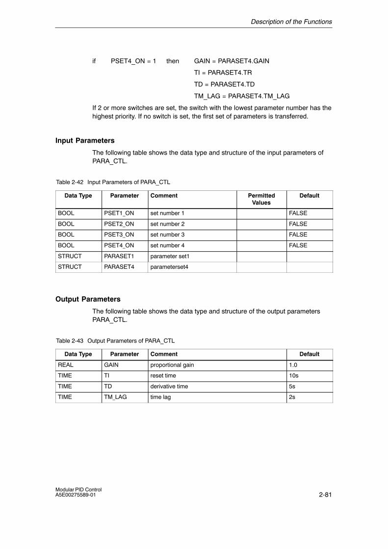
Description of the Functions
2-81Modular PID ControlA5E00275589-01
if PSET4_ON = 1 then GAIN = PARASET4.GAIN
TI = PARASET4.TR
TD = PARASET4.TD
TM_LAG = PARASET4.TM_LAG
If 2 or more switches are set, the switch with the lowest parameter number has thehighest priority. If no switch is set, the first set of parameters is transferred.
Input Parameters
The following table shows the data type and structure of the input parameters ofPARA_CTL.
Table 2-42 Input Parameters of PARA_CTL
Data Type Parameter Comment PermittedValues
Default
BOOL PSET1_ON set number 1 FALSE
BOOL PSET2_ON set number 2 FALSE
BOOL PSET3_ON set number 3 FALSE
BOOL PSET4_ON set number 4 FALSE
STRUCT PARASET1 parameter set1
STRUCT PARASET4 parameterset4
Output Parameters
The following table shows the data type and structure of the output parametersPARA_CTL.
Table 2-43 Output Parameters of PARA_CTL
Data Type Parameter Comment Default
REAL GAIN proportional gain 1.0
TIME TI reset time 10s
TIME TD derivative time 5s
TIME TM_LAG time lag 2s
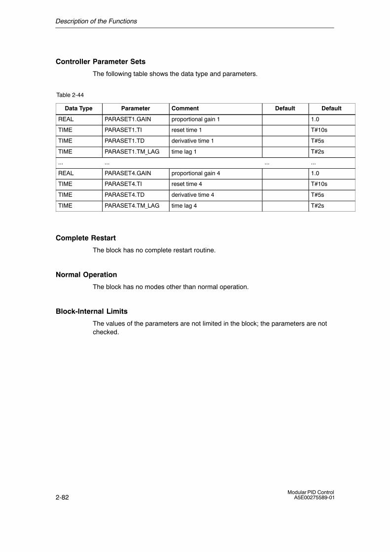
Description of the Functions
2-82Modular PID Control
A5E00275589-01
Controller Parameter Sets
The following table shows the data type and parameters.
Table 2-44
Data Type Parameter Comment Default Default
REAL PARASET1.GAIN proportional gain 1 1.0
TIME PARASET1.TI reset time 1 T#10s
TIME PARASET1.TD derivative time 1 T#5s
TIME PARASET1.TM_LAG time lag 1 T#2s
... ... ... ...
REAL PARASET4.GAIN proportional gain 4 1.0
TIME PARASET4.TI reset time 4 T#10s
TIME PARASET4.TD derivative time 4 T#5s
TIME PARASET4.TM_LAG time lag 4 T#2s
Complete Restart
The block has no complete restart routine.
Normal Operation
The block has no modes other than normal operation.
Block-Internal Limits
The values of the parameters are not limited in the block; the parameters are notchecked.
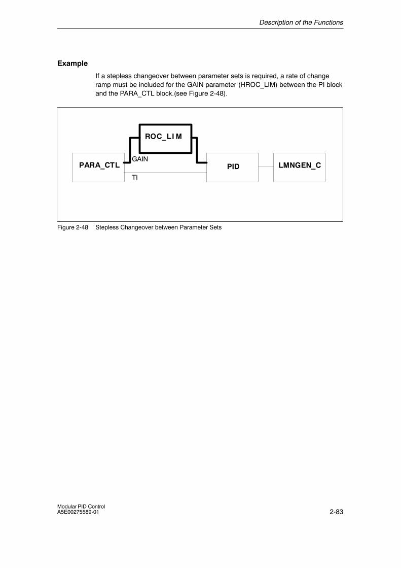
Description of the Functions
2-83Modular PID ControlA5E00275589-01
Example
If a stepless changeover between parameter sets is required, a rate of changeramp must be included for the GAIN parameter (HROC_LIM) between the PI blockand the PARA_CTL block.(see Figure 2-48).
PARA_CTL PID LMNGEN_C
ROC
GAIN
TI
_LI M
Figure 2-48 Stepless Changeover between Parameter Sets
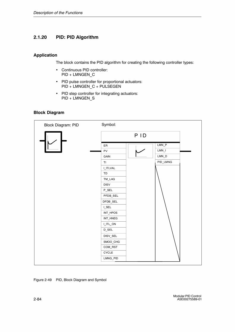
Description of the Functions
2-84Modular PID Control
A5E00275589-01
2.1.20 PID: PID Algorithm
Application
The block contains the PID algorithm for creating the following controller types:
• Continuous PID controller: PID + LMNGEN_C
• PID pulse controller for proportional actuators: PID + LMNGEN_C + PULSEGEN
• PID step controller for integrating actuators:PID + LMNGEN_S
Block Diagram
Symbol:
P I D
CYCLE
P_SEL
PFDB_SEL
LMN_P
LMN_I
LMN_D
I_ITL_ON
D_SEL
I_SEL
DISV_SEL
ER
PV
GAIN
I_ITLVAL
TD
TM_LAG
DISV
TI
COM_RST
LMNG_PID
PID_LMNG
DFDB_SEL
Block Diagram: PID
INT_HPOS
INT_HNEG
SMOO_CHG
Figure 2-49 PID, Block Diagram and Symbol
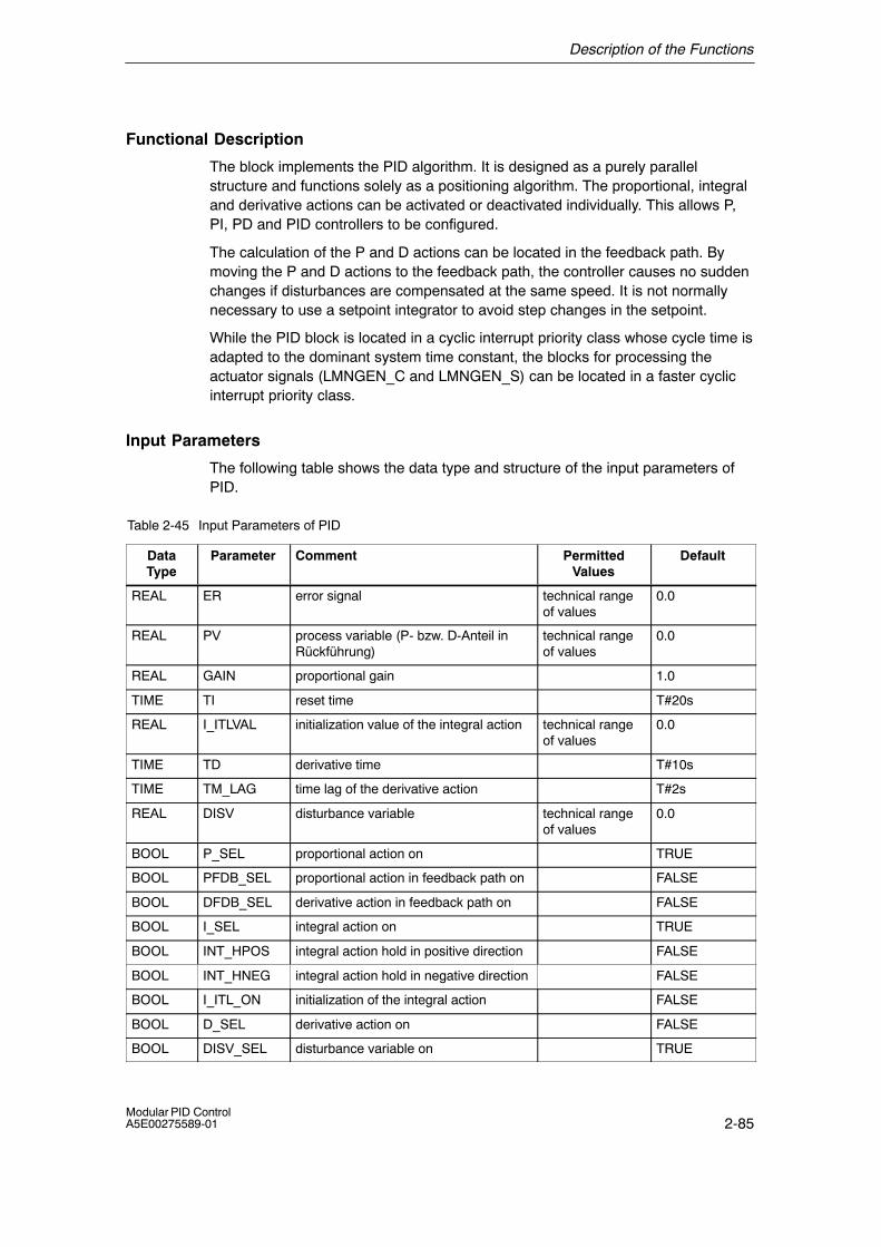
Description of the Functions
2-85Modular PID ControlA5E00275589-01
Functional Description
The block implements the PID algorithm. It is designed as a purely parallelstructure and functions solely as a positioning algorithm. The proportional, integraland derivative actions can be activated or deactivated individually. This allows P,PI, PD and PID controllers to be configured.
The calculation of the P and D actions can be located in the feedback path. Bymoving the P and D actions to the feedback path, the controller causes no suddenchanges if disturbances are compensated at the same speed. It is not normallynecessary to use a setpoint integrator to avoid step changes in the setpoint.
While the PID block is located in a cyclic interrupt priority class whose cycle time isadapted to the dominant system time constant, the blocks for processing theactuator signals (LMNGEN_C and LMNGEN_S) can be located in a faster cyclicinterrupt priority class.
Input Parameters
The following table shows the data type and structure of the input parameters ofPID.
Table 2-45 Input Parameters of PID
DataType
Parameter Comment PermittedValues
Default
REAL ER error signal technical rangeof values
0.0
REAL PV process variable (P- bzw. D-Anteil inRückführung)
technical rangeof values
0.0
REAL GAIN proportional gain 1.0
TIME TI reset time T#20s
REAL I_ITLVAL initialization value of the integral action technical rangeof values
0.0
TIME TD derivative time T#10s
TIME TM_LAG time lag of the derivative action T#2s
REAL DISV disturbance variable technical rangeof values
0.0
BOOL P_SEL proportional action on TRUE
BOOL PFDB_SEL proportional action in feedback path on FALSE
BOOL DFDB_SEL derivative action in feedback path on FALSE
BOOL I_SEL integral action on TRUE
BOOL INT_HPOS integral action hold in positive direction FALSE
BOOL INT_HNEG integral action hold in negative direction FALSE
BOOL I_ITL_ON initialization of the integral action FALSE
BOOL D_SEL derivative action on FALSE
BOOL DISV_SEL disturbance variable on TRUE
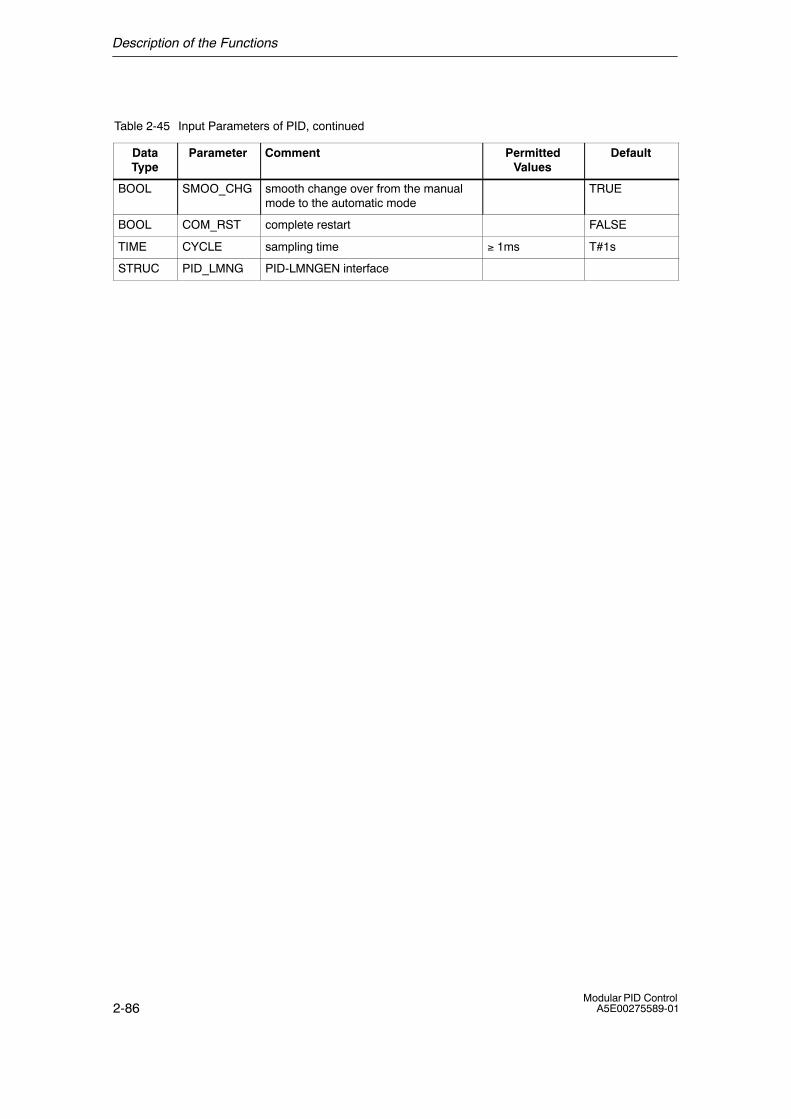
Description of the Functions
2-86Modular PID Control
A5E00275589-01
Table 2-45 Input Parameters of PID, continued
DataType
DefaultPermittedValues
CommentParameter
BOOL SMOO_CHG smooth change over from the manualmode to the automatic mode
TRUE
BOOL COM_RST complete restart FALSE
TIME CYCLE sampling time ≥ 1ms T#1s
STRUC PID_LMNG PID-LMNGEN interface
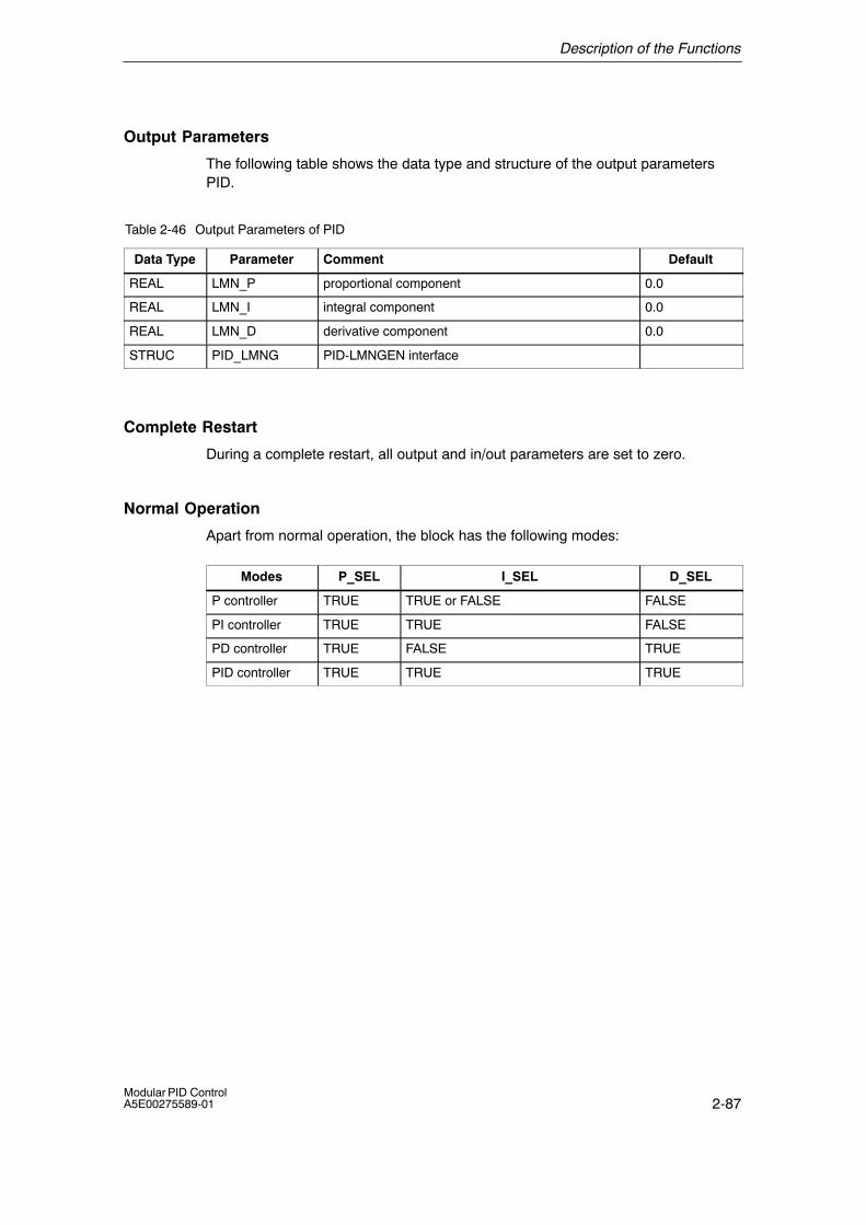
Description of the Functions
2-87Modular PID ControlA5E00275589-01
Output Parameters
The following table shows the data type and structure of the output parametersPID.
Table 2-46 Output Parameters of PID
Data Type Parameter Comment Default
REAL LMN_P proportional component 0.0
REAL LMN_I integral component 0.0
REAL LMN_D derivative component 0.0
STRUC PID_LMNG PID-LMNGEN interface
Complete Restart
During a complete restart, all output and in/out parameters are set to zero.
Normal Operation
Apart from normal operation, the block has the following modes:
Modes P_SEL I_SEL D_SEL
P controller TRUE TRUE or FALSE FALSE
PI controller TRUE TRUE FALSE
PD controller TRUE FALSE TRUE
PID controller TRUE TRUE TRUE
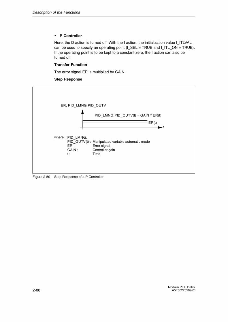
Description of the Functions
2-88Modular PID Control
A5E00275589-01
• P Controller
Here, the D action is turned off. With the I action, the initialization value I_ITLVALcan be used to specify an operating point (I_SEL = TRUE and I_ITL_ON = TRUE).If the operating point is to be kept to a constant zero, the I action can also beturned off.
Transfer Function
The error signal ER is multiplied by GAIN.
Step Response
t
where : PID_LMNG.PID_OUTV(t) :ER :GAIN :t :
PID_LMNG.PID_OUTV(t) = GAIN * ER(t)
ER, PID_LMNG.PID_OUTV
Manipulated variable automatic modeError signalController gainTime
ER(t)
Figure 2-50 Step Response of a P Controller
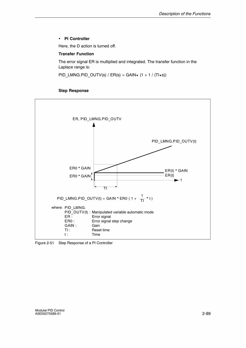
Description of the Functions
2-89Modular PID ControlA5E00275589-01
• PI Controller
Here, the D action is turned off.
Transfer Function
The error signal ER is multiplied and integrated. The transfer function in theLaplace range is:
PID_LMNG.PID_OUTV(s) / ER(s) = GAIN� (1 + 1 / (TI�s))
Step Response
ER(t) * GAIN
TI
t
PID_LMNG.PID_OUTV(t) = GAIN * ER0 ( 1 + * t )1TI
where: PID_LMNG.PID_OUTV(t) :ER :ER0 :GAIN :TI :t :
PID_LMNG.PID_OUTV(t)
ER, PID_LMNG.PID_OUTV
ER0 * GAIN
ER0 * GAIN
Manipulated variable automatic modeError signalError signal step changeGainReset timeTime
ER(t)
Figure 2-51 Step Response of a PI Controller
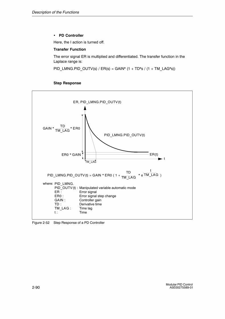
Description of the Functions
2-90Modular PID Control
A5E00275589-01
• PD Controller
Here, the I action is turned off.
Transfer Function
The error signal ER is multiplied and differentiated. The transfer function in theLaplace range is:
PID_LMNG.PID_OUTV(s) / ER(s) = GAIN* (1 + TD*s / (1 + TM_LAG*s))
Step Response
t
PID_LMNG.PID_OUTV(t) = GAIN * ER0 ( 1 + * e )
where: PID_LMNG.PID_OUTV(t) :ER :ER0 :GAIN :TD :TM_LAG :t :
PID_LMNG.PID_OUTV(t)
TD
TM_LAG
tTM_LAG
TM_LAG
ER0 * GAIN
GAIN * * ER0TD
TM_LAG
Manipulated variable automatic modeError signalError signal step changeController gainDerivative timeTime lagTime
ER(t)
ER, PID_LMNG.PID_OUTV(t)
Figure 2-52 Step Response of a PD Controller
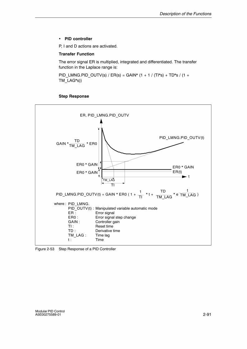
Description of the Functions
2-91Modular PID ControlA5E00275589-01
• PID controller
P, I and D actions are activated.
Transfer Function
The error signal ER is multiplied, integrated and differentiated. The transferfunction in the Laplace range is:
PID_LMNG.PID_OUTV(s) / ER(s) = GAIN* (1 + 1 / (TI*s) + TD*s / (1 +TM_LAG*s))
Step Response
ER0 * GAIN
TI
t
PID_LMNG.PID_OUTV(t) = GAIN * ER0 ( 1 + * t + * e )1TI
where : PID_LMNG.PID_OUTV(t) :ER :ER0 :GAIN :TI :TD :TM_LAG :t :
PID_LMNG.PID_OUTV(t)
ER, PID_LMNG.PID_OUTV
TD
TM_LAG
tTM_LAG
TM_LAG
ER0 * GAIN
ER0 * GAIN
GAIN * * ER0TD
TM_LAG
Manipulated variable automatic modeError signalError signal step changeController gainReset timeDerivative timeTime lagTime
ER(t)
Figure 2-53 Step Response of a PID Controller
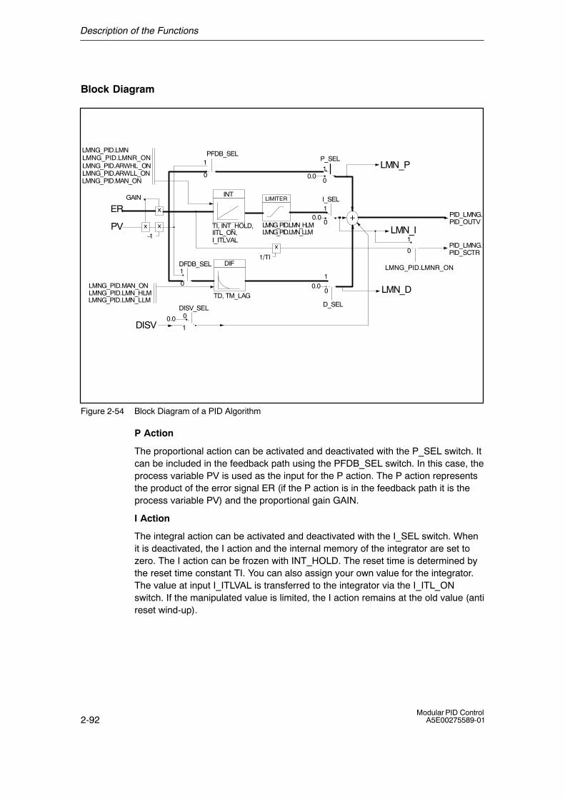
Description of the Functions
2-92Modular PID Control
A5E00275589-01
Block Diagram
x
x
GAIN
PFDB_SEL
TI, INT_HOLD,IITL_ON,I_ITLVAL
TD, TM_LAG
P_SEL
I_SEL
D_SEL
DFDB_SEL
+
0.0
0.0
0.0x
�1
0
11
1
0
0
0
10
1
LMN_D
LMN_I
LMN_P
DISV
DIF
INT
0
1
DISV_SEL
0.0
ER
PVPID_LMNG.PID_OUTV
LMNG_PID.MAN_ON
LMNG_PID.LMN_LLMLMNG_PID.LMN_HLM
PID_LMNG.PID_SCTR
LIMITER
x
1/TI
1
0
LMNG_PID.ARWLL_ONLMNG_PID.ARWHL_ON
LMNG_PID.LMN
LMNG_PID.MAN_ON
LMNG_PID.LMN_LLMLMNG_PID.LMN_HLM
LMNG_PID.LMNR_ON
LMNG_PID.LMNR_ON
Figure 2-54 Block Diagram of a PID Algorithm
P Action
The proportional action can be activated and deactivated with the P_SEL switch. Itcan be included in the feedback path using the PFDB_SEL switch. In this case, theprocess variable PV is used as the input for the P action. The P action representsthe product of the error signal ER (if the P action is in the feedback path it is theprocess variable PV) and the proportional gain GAIN.
I Action
The integral action can be activated and deactivated with the I_SEL switch. Whenit is deactivated, the I action and the internal memory of the integrator are set tozero. The I action can be frozen with INT_HOLD. The reset time is determined bythe reset time constant TI. You can also assign your own value for the integrator.The value at input I_ITLVAL is transferred to the integrator via the I_ITL_ONswitch. If the manipulated value is limited, the I action remains at the old value (antireset wind-up).
Description of the Functions
2-93Modular PID ControlA5E00275589-01
D Action
The D action can be activated and deactivated with the D_SEL switch. It can beincluded in the feedback path using the DFDB_SEL switch. The input value of theD action is then the negative process variable PV. The time response isdetermined by the derivative action time TD. A first-order time lag is integrated inthe derivative unit. The time lag is entered at TM_LAG.
Particularly in fast systems when the D action is active, unacceptable disturbancefluctuations can occur. In this case, the control quality can be improved by the timelag integrated in the D action. Usually a small TM_LAG is sufficient
Feedforward Control
A disturbance value DISV can be connected in addition to the manipulated value.This can be activated or deactivated using the DISV_SEL switch.
Block-Internal Limits
• The reset time is limited downwards to half the sampling time.
• The derivative time is limited downwards to the sampling time.
• The time lag is limited downwards to half the sampling time.
TIintern = CYCLE/2 when TI < CYCLE/2
TDintern = CYCLE when TD < CYCLE
TM_LAGintern = CYCLE/2 when TM_LAG < CYCLE/2
The values of the other input parameters are not limited in the block; theparameters are not checked.
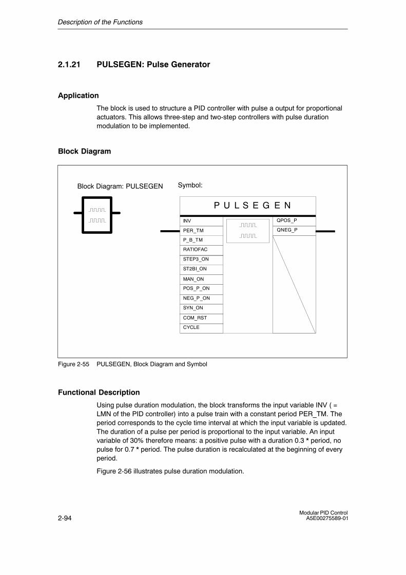
Description of the Functions
2-94Modular PID Control
A5E00275589-01
2.1.21 PULSEGEN: Pulse Generator
Application
The block is used to structure a PID controller with pulse a output for proportionalactuators. This allows three-step and two-step controllers with pulse durationmodulation to be implemented.
Block Diagram
Symbol:
P U L S E G E N
CYCLE
STEP3_ON
ST2BI_ON
QPOS_P
QNEG_P
MAN_ON
POS_P_ON
NEG_P_ON
SYN_ON
PER_TM
P_B_TM
RATIOFAC
INV
COM_RST
Block Diagram: PULSEGEN
Figure 2-55 PULSEGEN, Block Diagram and Symbol
Functional Description
Using pulse duration modulation, the block transforms the input variable INV ( =LMN of the PID controller) into a pulse train with a constant period PER_TM. Theperiod corresponds to the cycle time interval at which the input variable is updated.The duration of a pulse per period is proportional to the input variable. An inputvariable of 30% therefore means: a positive pulse with a duration 0.3 * period, nopulse for 0.7 * period. The pulse duration is recalculated at the beginning of everyperiod.
Figure 2-56 illustrates pulse duration modulation.
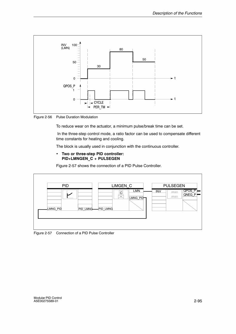
Description of the Functions
2-95Modular PID ControlA5E00275589-01
t
INV
��� ��
(LMN)
0
50
100
1
0 t
������
�)���
30
50
80
Figure 2-56 Pulse Duration Modulation
To reduce wear on the actuator, a minimum pulse/break time can be set.
In the three-step control mode, a ratio factor can be used to compensate differenttime constants for heating and cooling.
The block is usually used in conjunction with the continuous controller.
• Two or three-step PID controller:PID+LMNGEN_C + PULSEGEN
Figure 2-57 shows the connection of a PID Pulse Controller.
QPOS_PQNEG_P
INVLMN
LIMGEN_CPID PULSEGEN
C
LMNG_PID PID_LMNGPID_LMNG
LMNG_PID
Figure 2-57 Connection of a PID Pulse Controller
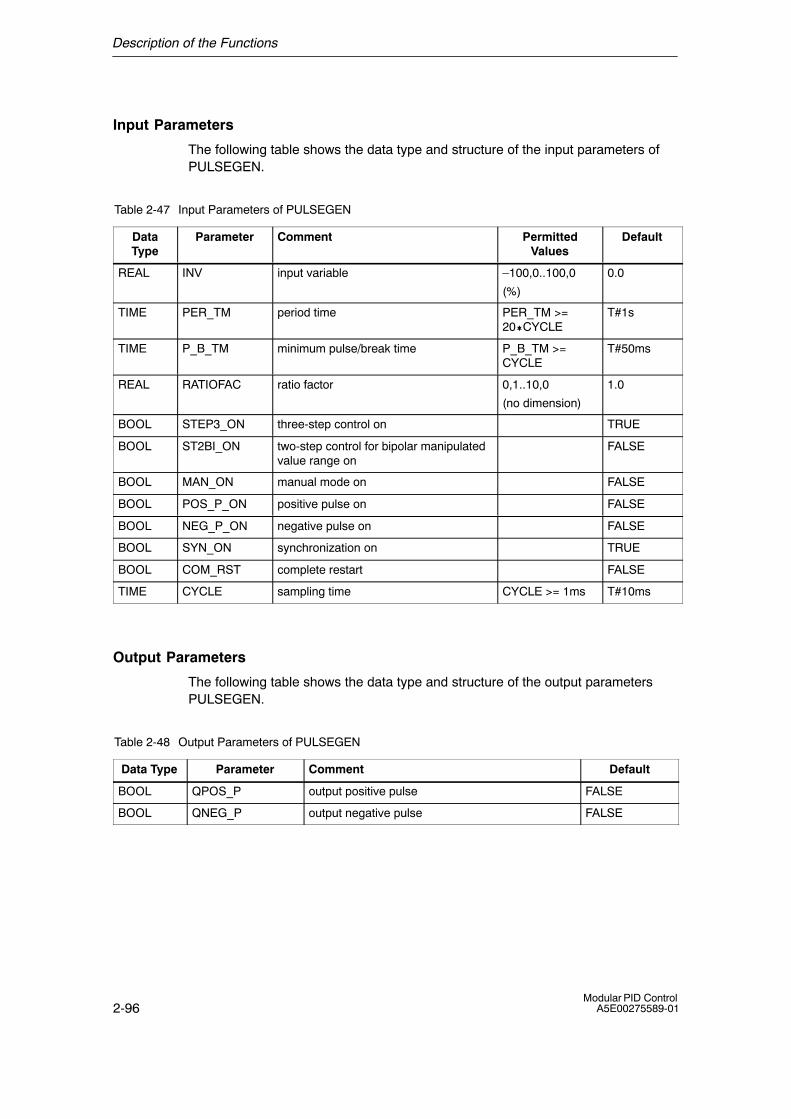
Description of the Functions
2-96Modular PID Control
A5E00275589-01
Input Parameters
The following table shows the data type and structure of the input parameters ofPULSEGEN.
Table 2-47 Input Parameters of PULSEGEN
DataType
Parameter Comment PermittedValues
Default
REAL INV input variable �100,0..100,0
(%)
0.0
TIME PER_TM period time PER_TM >=20�CYCLE
T#1s
TIME P_B_TM minimum pulse/break time P_B_TM >=CYCLE
T#50ms
REAL RATIOFAC ratio factor 0,1..10,0
(no dimension)
1.0
BOOL STEP3_ON three-step control on TRUE
BOOL ST2BI_ON two-step control for bipolar manipulatedvalue range on
FALSE
BOOL MAN_ON manual mode on FALSE
BOOL POS_P_ON positive pulse on FALSE
BOOL NEG_P_ON negative pulse on FALSE
BOOL SYN_ON synchronization on TRUE
BOOL COM_RST complete restart FALSE
TIME CYCLE sampling time CYCLE >= 1ms T#10ms
Output Parameters
The following table shows the data type and structure of the output parametersPULSEGEN.
Table 2-48 Output Parameters of PULSEGEN
Data Type Parameter Comment Default
BOOL QPOS_P output positive pulse FALSE
BOOL QNEG_P output negative pulse FALSE
Description of the Functions
2-97Modular PID ControlA5E00275589-01
Complete Restart
During a complete restart, all signal outputs are set to zero.
Accuracy of Pulse Generation
The implementation of this function in the CPU requires a decision about thecurrent status of the binary signal n times at points in the cycle within a period ofthe controller output. The higher the value of n, the more accurate the pulseduration modulation.
While the continuous PID controller (PID�LMNGEN_C) is located in a slow cyclicinterrupt priority class whose cycle time is adapted to the dominant system timeconstant, the PULSEGEN block must be located in a faster cyclic interrupt priorityclass. The faster the cyclic interrupt priority class, the greater the accuracy withwhich the manipulated value can be output. By using a cyclic interrupt priority classthat is 100 times faster, you can achieve a resolution of 1% of the manipulatedvalue range.
It is possible to synchronize the pulse output with the block that updates the inputvariable INV (for example PID_C) automatically. This ensures that a changing inputvariable is output as a pulse in the shortest possible time.
Automatic Synchronization
It is possible to synchronize the pulse output with the controller FB automatically.This ensures that a change in the value of the manipulated variable LMN(t) isoutput in the shortest possible time as a binary signal with a proportionally modifiedpulse duration.
The pulse generator evaluates the input variable INV at intervals corresponding tothe period PER_TM. Since, however, INV is calculated in a slower cyclic interruptpriority class, the pulse generator should begin to convert the discrete value into apulse signal as soon as possible after INV has been updated. To allow this, theblock can synchronize the start of the period itself as explained below:
If INV has changed and if the block call is not in the first or in the last two callcycles of a period, synchronization is performed. The pulse duration is recalculatedand in the next cycle, output starts with a new period.
The period PER_TM must correspond to the sampling time CYCLE of thecontroller.

Description of the Functions
2-98Modular PID Control
A5E00275589-01
�)�����:��� �6��
t
ÇÇÇÇÇÇÇÇÇÇÇÇÇÇÇÇ
ÇÇ
ÇÇÇÇ
t
ÇÇÇÇÇÇÇÇÇÇÇÇÇÇÇÇÇÇÇÇ
ÇÇÇÇ
����4���<�4�'& ����4���<�4�=& ����4���<�4�(&
�)�����:������
ÇÇ
������ ������
� � �� � �� � � �� ��
&� &� &� &
&� &� &� &
���+��� 2!��!
/ -��� +>�!+� � �:� !��1��+��� 2!��!
��� �6�����!�-!23� ��<� ��2� -�� ;��� ��!���-�""� +2� �!� + �!���:+�2!�-/-"����"�2!� !?��-/-"�2��:� !���1��+��
��� �6�����!�-!23� ��<� ��2� -�� ;��!��=&����(&�� ��!���-�""� +2�+ �!���:+�2!-/-"����� "�2!� !?��-/-"�2��:� !���1��+��
ÇÇÇÇ
���-�22+ ;� ��� �6�� ���-�22+ ;���� �6���+ � !��� :+�2!�-/-"����� + � !��� "�2!� !?��-/-"�2��:� !���1��+��
���-�22+ ;� �����
��� 2/ -��� +>�!+� � �-�22��/
Figure 2-58 Synchronization of the Start of the Period
Automatic synchronization can be turned off at input �SYN_ON� (= FALSE).
Note
With the start of the new period after synchronization, the old value of INV (inother words of LMN) is simulated more or less inaccurately by the pulse signal.
Modes of the Controller with Pulse Output
Depending on the parameter settings of the pulse generator, PID controllers withthree-step output or with bipolar or monopolar two-step output are configured. Thefollowing table shows the switch combinations for the possible modes.
ModeSwitch MAN_ON STEP3_ON ST2BI_ON
Three-step controller FALSE TRUE any
Two-step controller with bipolarrange (-100 % to 100 %)
FALSE FALSE TRUE
Two-step controller with monopolarrange (0 % to 100 %)
FALSE FALSE FALSE
Manual mode TRUE any any
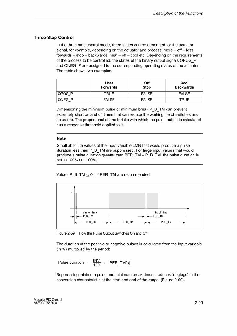
Description of the Functions
2-99Modular PID ControlA5E00275589-01
Three-Step Control
In the three-step control mode, three states can be generated for the actuatorsignal, for example, depending on the actuator and process: more � off � less,forwards � stop � backwards, heat � off � cool etc. Depending on the requirementsof the process to be controlled, the states of the binary output signals QPOS_Pand QNEG_P are assigned to the corresponding operating states of the actuator.The table shows two examples.
HeatForwards
OffStop
CoolBackwards
QPOS_P TRUE FALSE FALSE
QNEG_P FALSE FALSE TRUE
Dimensioning the minimum pulse or minimum break P_B_TM can preventextremely short on and off times that can reduce the working life of switches andactuators. The proportional characteristic with which the pulse output is calculatedhas a response threshold applied to it.
Note
Small absolute values of the input variable LMN that would produce a pulseduration less than P_B_TM are suppressed. For large input values that wouldproduce a pulse duration greater than PER_TM � P_B_TM, the pulse duration isset to 100% or �100%.
Values P_B_TM � 0.1 * PER_TM are recommended.
������ ������
9+ &�� �!+9�������
9+ &� �::� !+9�������
�
������
Figure 2-59 How the Pulse Output Switches On and Off
The duration of the positive or negative pulses is calculated from the input variable(in %) multiplied by the period:
INV100
Pulse duration = * PER_TM[s]
Suppressing minimum pulse and minimum break times produces �doglegs� in theconversion characteristic at the start and end of the range. (Figure 2-60).
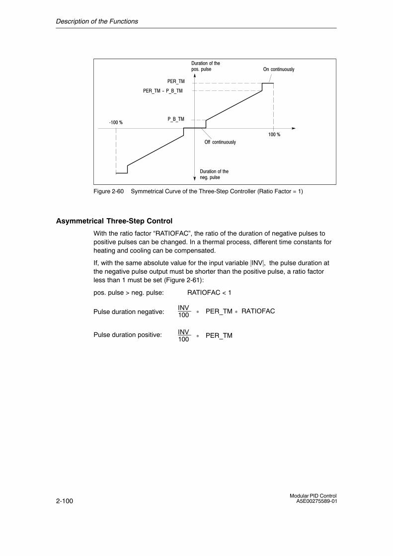
Description of the Functions
2-100Modular PID Control
A5E00275589-01
�0��!+� ��:�!��1�2&� 10"2�
@��A
��A
������
�������B�������
������
�::� -� !+ 0�02"/
� � -� !+ 0�02"/
�0��!+� ��:� !�� �;&�10"2�
Figure 2-60 Symmetrical Curve of the Three-Step Controller (Ratio Factor = 1)
Asymmetrical Three-Step Control
With the ratio factor �RATIOFAC�, the ratio of the duration of negative pulses topositive pulses can be changed. In a thermal process, different time constants forheating and cooling can be compensated.
If, with the same absolute value for the input variable |INV|, the pulse duration atthe negative pulse output must be shorter than the positive pulse, a ratio factorless than 1 must be set (Figure 2-61):
pos. pulse > neg. pulse: RATIOFAC < 1
INV100Pulse duration negative: * PER_TM * RATIOFAC
INV100
Pulse duration positive: * PER_TM

Description of the Functions
2-101Modular PID ControlA5E00275589-01
�0��!+� ��:�!��1�2&� 10"2�
@��A
��A
������
�������B�������
������
�0��!+� ��:� !�� �;&�10"2�
&(� 5�������&(�5���������B��������
&(�5�������
Figure 2-61 Asymmetrical Curve of the Three-step Controller (Ratio Factor = 0.5)
If the opposite is required, so that with the same absolute value for the inputvariable |INV|, the pulse duration at the positive pulse output is shorter than thenegative pulse, a ratio factor greater than 1 must be set:
pos. pulse < neg. pulse: RATIOFAC > 1
INV100Pulse duration negative: * PER_TM
INV * PER_TM100 * RATIOFAC
Pulse duration postitive:
The ratio factor also influences the minimum pulse and minimum break times.Mathematically, this means that with RATIOFAC < 1, the on threshold for negativepulses is multiplied by the ratio factor and with RATIOFAC > 1 the on threshold forpositive pulses is divided by the ratio factor.
Two-Step Control
In a two-step control, only positive pulse output QPOS_P of PULSEGEN isconnected to the on/off actuator. Depending on the actuating range, LMN = �100.0... 100.0 % or LMN = 0.0 % ... 100.0 %, the two-step controller has a bipolar ormonopolar actuating range.
In the monopolar mode, the input variable INV can only have values between 0.0and 100%.
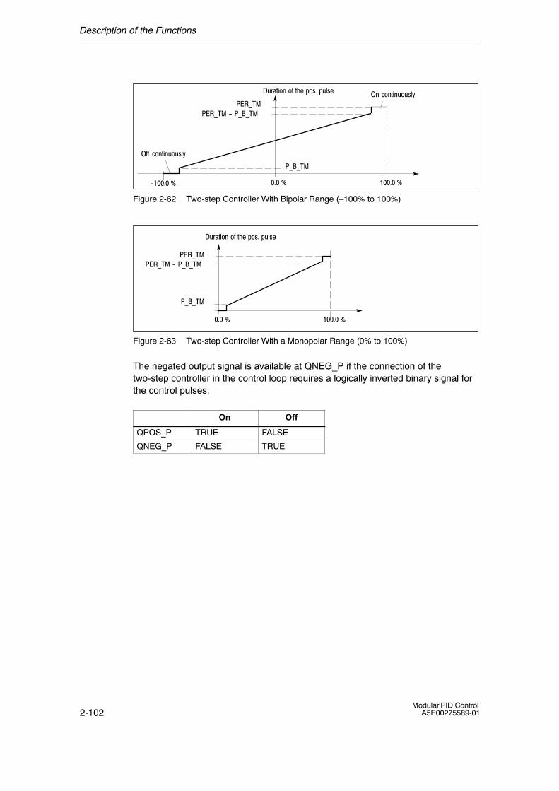
Description of the Functions
2-102Modular PID Control
A5E00275589-01
�0��!+� ��:� !���1�2&�10"2�
B�&�A �&�A
������
�������B�������
������
�::� -� !+ 0�02"/
� � -� !+ 0�02"/
&�A
Figure 2-62 Two-step Controller With Bipolar Range (�100% to 100%)
�0��!+� ��:� !���1�2&�10"2�
�&�A
������
�������B�������
������
&�A
Figure 2-63 Two-step Controller With a Monopolar Range (0% to 100%)
The negated output signal is available at QNEG_P if the connection of thetwo-step controller in the control loop requires a logically inverted binary signal forthe control pulses.
On Off
QPOS_P TRUE FALSE
QNEG_P FALSE TRUE
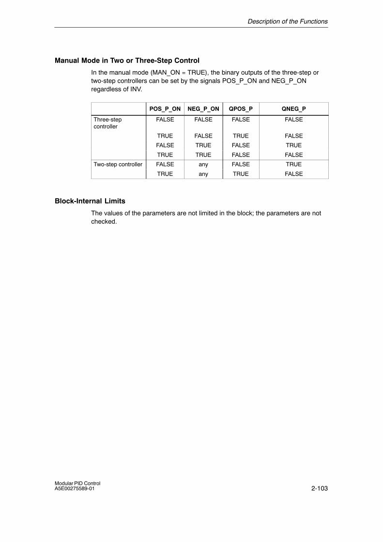
Description of the Functions
2-103Modular PID ControlA5E00275589-01
Manual Mode in Two or Three-Step Control
In the manual mode (MAN_ON = TRUE), the binary outputs of the three-step ortwo-step controllers can be set by the signals POS_P_ON and NEG_P_ONregardless of INV.
POS_P_ON NEG_P_ON QPOS_P QNEG_P
Three-stepcontroller
FALSE FALSE FALSE FALSE
TRUE FALSE TRUE FALSE
FALSE TRUE FALSE TRUE
TRUE TRUE FALSE FALSE
Two-step controller FALSE any FALSE TRUE
TRUE any TRUE FALSE
Block-Internal Limits
The values of the parameters are not limited in the block; the parameters are notchecked.
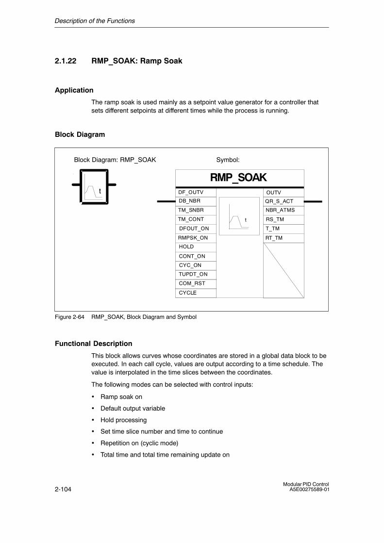
Description of the Functions
2-104Modular PID Control
A5E00275589-01
2.1.22 RMP_SOAK: Ramp Soak
Application
The ramp soak is used mainly as a setpoint value generator for a controller thatsets different setpoints at different times while the process is running.
Block Diagram
Symbol:
RMP_SOAKt
t
COM_RST
DFOUT_ON
DF_OUTV
RMPSK_ON
CYC_ON
HOLD
CONT_ON
TM_CONT
OUTV
QR_S_ACT
NBR_ATMS
RS_TM
DB_NBR
TM_SNBR
TUPDT_ON
T_TM
CYCLE
Block Diagram: RMP_SOAK
RT_TM
Figure 2-64 RMP_SOAK, Block Diagram and Symbol
Functional Description
This block allows curves whose coordinates are stored in a global data block to beexecuted. In each call cycle, values are output according to a time schedule. Thevalue is interpolated in the time slices between the coordinates.
The following modes can be selected with control inputs:
• Ramp soak on
• Default output variable
• Hold processing
• Set time slice number and time to continue
• Repetition on (cyclic mode)
• Total time and total time remaining update on
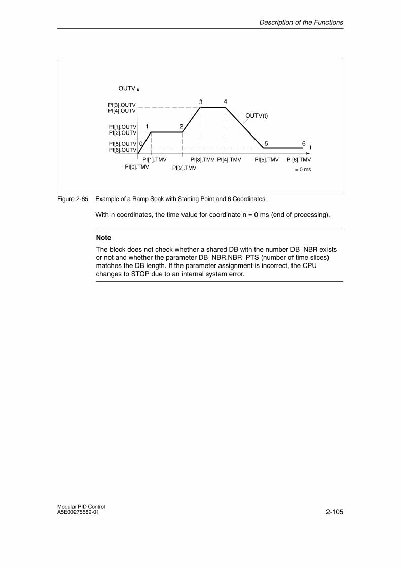
Description of the Functions
2-105Modular PID ControlA5E00275589-01
t
PI[3].OUTV
OUTV(t)
PI[1].TMV
PI[2].TMV
PI[3].TMV PI[4].TMV PI[5].TMV PI[6].TMV
PI[4].OUTV
PI[1].OUTVPI[2].OUTV
PI[0].TMV
PI[5].OUTVPI[6].OUTV
65
43
21
0
= 0 ms
OUTV
Figure 2-65 Example of a Ramp Soak with Starting Point and 6 Coordinates
With n coordinates, the time value for coordinate n = 0 ms (end of processing).
Note
The block does not check whether a shared DB with the number DB_NBR existsor not and whether the parameter DB_NBR.NBR_PTS (number of time slices)matches the DB length. If the parameter assignment is incorrect, the CPUchanges to STOP due to an internal system error.
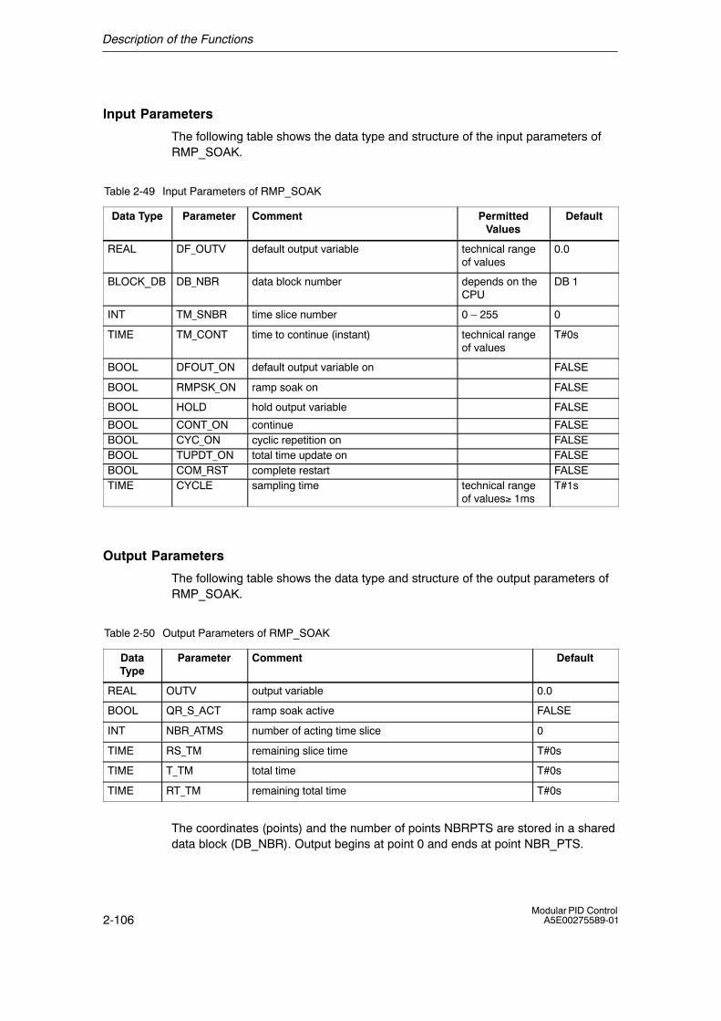
Description of the Functions
2-106Modular PID Control
A5E00275589-01
Input Parameters
The following table shows the data type and structure of the input parameters ofRMP_SOAK.
Table 2-49 Input Parameters of RMP_SOAK
Data Type Parameter Comment PermittedValues
Default
REAL DF_OUTV default output variable technical rangeof values
0.0
BLOCK_DB DB_NBR data block number depends on theCPU
DB 1
INT TM_SNBR time slice number 0 � 255 0
TIME TM_CONT time to continue (instant) technical rangeof values
T#0s
BOOL DFOUT_ON default output variable on FALSE
BOOL RMPSK_ON ramp soak on FALSE
BOOL HOLD hold output variable FALSE
BOOL CONT_ON continue FALSEBOOL CYC_ON cyclic repetition on FALSEBOOL TUPDT_ON total time update on FALSEBOOL COM_RST complete restart FALSETIME CYCLE sampling time technical range
of values≥ 1msT#1s
Output Parameters
The following table shows the data type and structure of the output parameters ofRMP_SOAK.
Table 2-50 Output Parameters of RMP_SOAK
DataType
Parameter Comment Default
REAL OUTV output variable 0.0
BOOL QR_S_ACT ramp soak active FALSE
INT NBR_ATMS number of acting time slice 0
TIME RS_TM remaining slice time T#0s
TIME T_TM total time T#0s
TIME RT_TM remaining total time T#0s
The coordinates (points) and the number of points NBRPTS are stored in a shareddata block (DB_NBR). Output begins at point 0 and ends at point NBR_PTS.
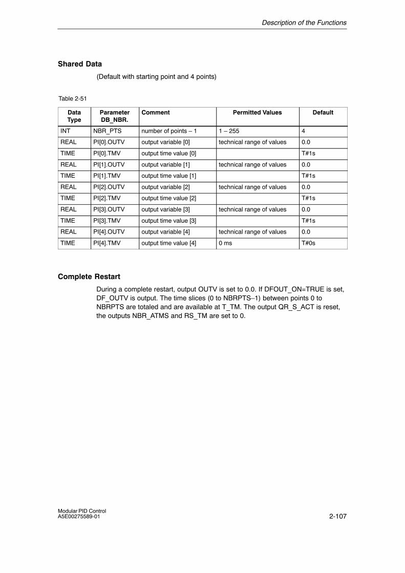
Description of the Functions
2-107Modular PID ControlA5E00275589-01
Shared Data
(Default with starting point and 4 points)
Table 2-51
DataType
ParameterDB_NBR.
Comment Permitted Values Default
INT NBR_PTS number of points � 1 1 � 255 4
REAL PI[0].OUTV output variable [0] technical range of values 0.0
TIME PI[0].TMV output time value [0] T#1s
REAL PI[1].OUTV output variable [1] technical range of values 0.0
TIME PI[1].TMV output time value [1] T#1s
REAL PI[2].OUTV output variable [2] technical range of values 0.0
TIME PI[2].TMV output time value [2] T#1s
REAL PI[3].OUTV output variable [3] technical range of values 0.0
TIME PI[3].TMV output time value [3] T#1s
REAL PI[4].OUTV output variable [4] technical range of values 0.0
TIME PI[4].TMV output time value [4] 0 ms T#0s
Complete Restart
During a complete restart, output OUTV is set to 0.0. If DFOUT_ON=TRUE is set,DF_OUTV is output. The time slices (0 to NBRPTS�1) between points 0 toNBRPTS are totaled and are available at T_TM. The output QR_S_ACT is reset,the outputs NBR_ATMS and RS_TM are set to 0.

Description of the Functions
2-108Modular PID Control
A5E00275589-01
Normal Operation
• The coordinate parameters NBR_PTS, PI[i].TMV and PI[i].OUTV are stored ina shared data block.
• The parameter PI[i].TMV must be specified in the TIME format.
• The way in which the point values and time slice are counted is illustrated in thefollowing schematic:
PI[0].OUTVPI[0].TMV
Startingpoint
t
Point 2
Point 1OUTV
PI[1].TMVPI[0].TMV
PI[1].OUTVPI[1].TMV
PI[2].OUTV
PI[2].TMV
PI[2].TMV
Figure 2-66 Counting the Coordinates and Time Slices
In normal operation, the ramp soak interpolates according to the following functionwhere 0 � n < (NBR_PTS � 1):
OUTV(t) � PI[n � 1].OUTV �RS_TM
PI[n].TMV(PI[n � 1].OUTV � PI[n].OUTV)
Modes of the Ramp Soak
To influence the control inputs, the following states and modes of the ramp soakcan be implemented:
1. Ramp soak on for one run
2. Default value at output of the ramp soak
3. Cyclic ramp soak mode on
4. Hold ramp soak
5. Time slice number and time to continue (the remaining slice time RS_TM andthe point number TM_SNBR are redefined)
6. Update total time and total time remaining
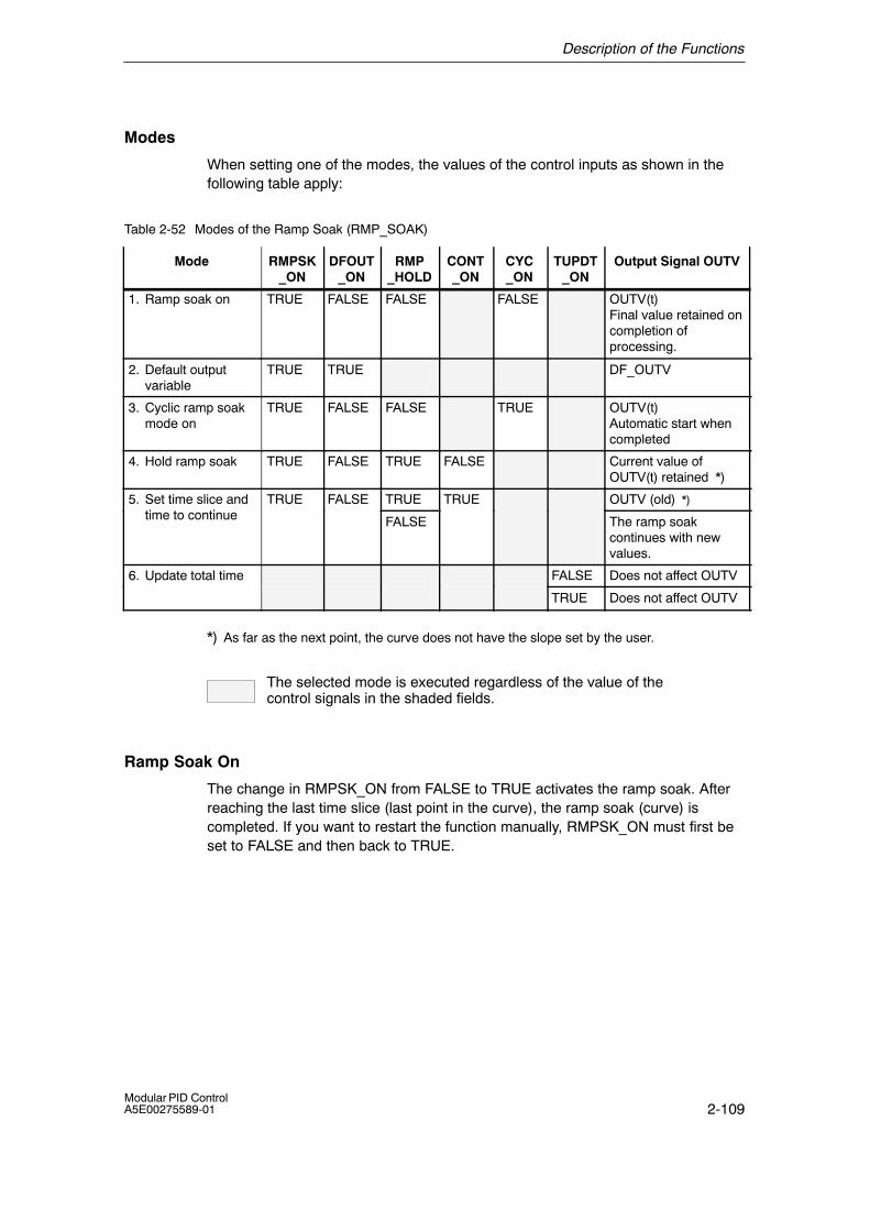
Description of the Functions
2-109Modular PID ControlA5E00275589-01
Modes
When setting one of the modes, the values of the control inputs as shown in thefollowing table apply:
Table 2-52 Modes of the Ramp Soak (RMP_SOAK)
Mode RMPSK_ON
DFOUT_ON
RMP_HOLD
CONT_ON
CYC_ON
TUPDT_ON
Output Signal OUTV
1. Ramp soak on TRUE FALSE FALSE FALSE OUTV(t)Final value retained oncompletion ofprocessing.
2. Default output variable
TRUE TRUE DF_OUTV
3. Cyclic ramp soak mode on
TRUE FALSE FALSE TRUE OUTV(t)Automatic start whencompleted
4. Hold ramp soak TRUE FALSE TRUE FALSE Current value ofOUTV(t) retained *)
5. Set time slice andti t ti
TRUE FALSE TRUE TRUE OUTV (old) *)time to continue FALSE The ramp soak
continues with newvalues.
6. Update total time FALSE Does not affect OUTV
TRUE Does not affect OUTV
*) As far as the next point, the curve does not have the slope set by the user.
The selected mode is executed regardless of the value of the control signals in the shaded fields.
Ramp Soak On
The change in RMPSK_ON from FALSE to TRUE activates the ramp soak. Afterreaching the last time slice (last point in the curve), the ramp soak (curve) iscompleted. If you want to restart the function manually, RMPSK_ON must first beset to FALSE and then back to TRUE.
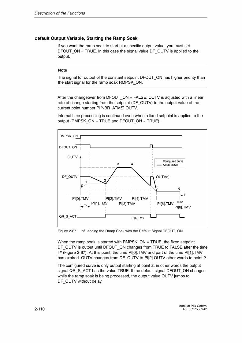
Description of the Functions
2-110Modular PID Control
A5E00275589-01
Default Output Variable, Starting the Ramp Soak
If you want the ramp soak to start at a specific output value, you must setDFOUT_ON = TRUE. In this case the signal value DF_OUTV is applied to theoutput.
Note
The signal for output of the constant setpoint DFOUT_ON has higher priority thanthe start signal for the ramp soak RMPSK_ON.
After the changeover from DFOUT_ON = FALSE, OUTV is adjusted with a linearrate of change starting from the setpoint (DF_OUTV) to the output value of thecurrent point number PI[NBR_ATMS].OUTV.
Internal time processing is continued even when a fixed setpoint is applied to theoutput (RMPSK_ON = TRUE and DFOUT_ON = TRUE).
t
OUTV(t)
PI[6].TMV
65
43
210
OUTV
RMPSK_ON
DFOUT_ON
DF_OUTV
T*
QR_S_ACT
�� :+;0����-0�C��-!0�"� -0�C�
0 msPI[5].TMVPI[4].TMV
PI[3].TMVPI[2].TMVPI[0].TMV
PI[1].TMVPI[6].TMV
Figure 2-67 Influencing the Ramp Soak with the Default Signal DFOUT_ON
When the ramp soak is started with RMPSK_ON = TRUE, the fixed setpointDF_OUTV is output until DFOUT_ON changes from TRUE to FALSE after the timeT* (Figure 2-67). At this point, the time PI[0].TMV and part of the time PI[1].TMVhas expired. OUTV changes from DF_OUTV to PI[2].OUTV other words to point 2.
The configured curve is only output starting at point 2, in other words the outputsignal QR_S_ACT has the value TRUE. If the default signal DFOUT_ON changeswhile the ramp soak is being processed, the output value OUTV jumps toDF_OUTV without delay.
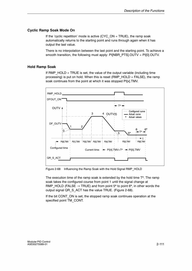
Description of the Functions
2-111Modular PID ControlA5E00275589-01
Cyclic Ramp Soak Mode On
If the �cyclic repetition� mode is active (CYC_ON = TRUE), the ramp soakautomatically returns to the starting point and runs through again when it hasoutput the last value.
There is no interpolation between the last point and the starting point. To achieve asmooth transition, the following must apply: PI[NBR_PTS].OUTV = PI[0].OUTV.
Hold Ramp Soak
If RMP_HOLD = TRUE is set, the value of the output variable (including timeprocessing) is put on hold. When this is reset (RMP_HOLD = FALSE), the rampsoak continues from the point at which it was stopped PI[x].TMV.
t
OUTV(t)
6*5*
43
20
OUTV
RMP_HOLD
DFOUT_ON
DF_OUTV
T*
QR_S_ACT
�� :+;0����-0�C��-!0�"� -0�C��-!0�"� C�"0�2
5
1
T*6
PI[4].TMV+T* PI[5].TMVCurrent time:
*
��#8$&��< ��#($&��<��#�$&��<
Configured time
��#%$&��<��#$&��< ��#'$&��< ��#D$&��<
Figure 2-68 Influencing the Ramp Soak with the Hold Signal RMP_HOLD
The execution time of the ramp soak is extended by the hold time T*. The rampsoak takes the configured course from point 1 until the signal change atRMP_HOLD (FALSE → TRUE) and from point 5* to point 6*, in other words theoutput signal QR_S_ACT has the value TRUE. (Figure 2-68).
If the bit CONT_ON is set, the stopped ramp soak continues operation at thespecified point TM_CONT.

Description of the Functions
2-112Modular PID Control
A5E00275589-01
Time Slice and Time to Continue
If the control input CONT_ON for the continuation of the ramp soak is set toTRUE, the ramp soak continues at TM_CONT (time to continue) with pointTM_SNBR (destination point). The time parameter TM_CONT determines theremaining time that the ramp soak requires to the destination point TM_SNBR.
�-!0�" � !+9�3
t
OUTV(t)
65*
43
20
OUTV
CONT_ON
T*
QR_S_ACT
�� :+;0����-0�C��-!0�"� -0�C��-!0�"� C�"0�2
5
1
6*
��#($&��<
*
��#8$&��< ��#($&��<��#�$&��<
�� :+;0���� !+9� T*
No reaction!
RMP_HOLD
��#'$&��<��#%$&��<��#$&��<
��#D$&��<
Figure 2-69 Influencing the Ramp Soak of the Hold Signal RMP_HOLD and the Continue
Signal CONT_ON
In the example (Figure 2-69), if RMP_HOLD = TRUE and CONT_ON = TRUE andif the following are set:
time slice to continue TM_SNBR = 5
and remaining time to required point TM_CONT = T*
for the processing cycle of the ramp soak, configured points 3 and 4 are omitted.After a signal change at RMP_HOLD from TRUE to FALSE, the configured curveis only achieved again starting at point 5.
The output QR_S_ACT is only set , when the ramp soak has worked through thecurve selected by the user.
Description of the Functions
2-113Modular PID ControlA5E00275589-01
Update Total Time and Total Time Remaining
In every cycle, the current point number NBR_ATMS, the current actual remainingtime until the curve point is reached RS_TM, the total time T_TM and the total timeremaining to the end of the curve RT_TM are updated.
If PI[n].TMV is changed online, the total time and the total time remaining to theend of the curve are also changed. Since the calculation of T_TM and RT_TMgreatly increases the run time of the function block when there is a large number oftime slices, the calculation is only made after a complete restart or whenTUPDT_ON = TRUE is set. The time slices PI[0 ... NBR_PTS].TMV between theindividual curve points are totaled and indicated at the outputs total time T_TM andtotal time remaining RT_TM.
Please note that determining the total times means a relatively long CPU run time!
Block-Internal Limits
The values of the parameters are not limited in the block; the parameters are notchecked.
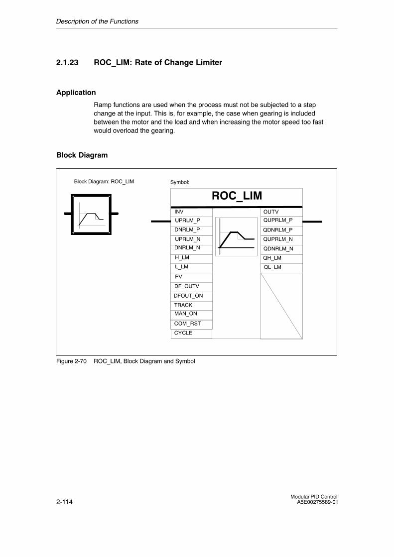
Description of the Functions
2-114Modular PID Control
A5E00275589-01
2.1.23 ROC_LIM: Rate of Change Limiter
Application
Ramp functions are used when the process must not be subjected to a stepchange at the input. This is, for example, the case when gearing is includedbetween the motor and the load and when increasing the motor speed too fastwould overload the gearing.
Block Diagram
ROC_LIM
COM_RST
DFOUT_ON
DF_OUTV
TRACK
INV
DNRLM_N
UPRLM_N
DNRLM_P
UPRLM_P
L_LM
H_LM
MAN_ON
PV
QDNRLM_N
QUPRLM_N
QDNRLM_P
QUPRLM_P
QL_LM
QH_LM
Symbol:
OUTV
CYCLE
Block Diagram: ROC_LIM
Figure 2-70 ROC_LIM, Block Diagram and Symbol
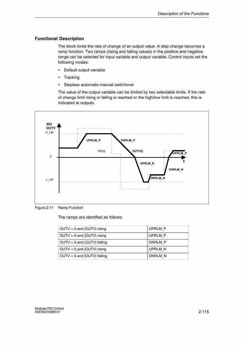
Description of the Functions
2-115Modular PID ControlA5E00275589-01
Functional Description
The block limits the rate of change of an output value. A step change becomes aramp function. Two ramps (rising and falling values) in the positive and negativerange can be selected for input variable and output variable. Control inputs set thefollowing modes:
• Default output variable
• Tracking
• Stepless automatic-manual switchover
The value of the output variable can be limited by two selectable limits. If the rateof change limit rising or falling is reached or the high/low limit is reached, this isindicated at outputs.
0
INV(t) OUTV(t)
DNRLM_N
UPRLM_N
UPRLM_P DNRLM_P
L_LM
H_LM
DNRLM_N
t
INVOUTV
UPRLM_P
Figure 2-71 Ramp Function
The ramps are identified as follows:
OUTV > 0 and |OUTV| rising UPRLM_P
OUTV > 0 and |OUTV| rising UPRLM_P
OUTV > 0 and |OUTV| falling DNRLM_P
OUTV < 0 and |OUTV| rising UPRLM_N
OUTV < 0 and |OUTV| falling DNRLM_N

Description of the Functions
2-116Modular PID Control
A5E00275589-01
Input Parameters
The following table shows the data type and structure of the input parameters ofROC_LIM.
Table 2-53
DataType
Parameter Comment PermittedValues
Default
REAL INV input variable technical rangeof values
0.0
REAL UPRLM_P up rate limit in positive range > 0.0 10.0
REAL DNRLM_P down rate limit in positive range > 0.0 10.0
REAL UPRLM_N up rate limit in negative range > 0.0 10.0
REAL DNRLM_N down rate limit in negative range > 0.0 10.0
REAL H_LM high limit tech. range
> L_LM
100.0
REAL L_LM low limit tech. range
< H_LM
0.0
REAL PV process variable technical rangeof values
0.0
REAL DF_OUTV default output variable technical rangeof values
0.0
BOOL DFOUT_ON default output variable on FALSE
BOOL TRACK tracking OUTV = INV FALSE
BOOL MAN_ON manual mode on FALSE
BOOL COM_RST complete restart FALSE
TIME CYCLE sampling time T#1s
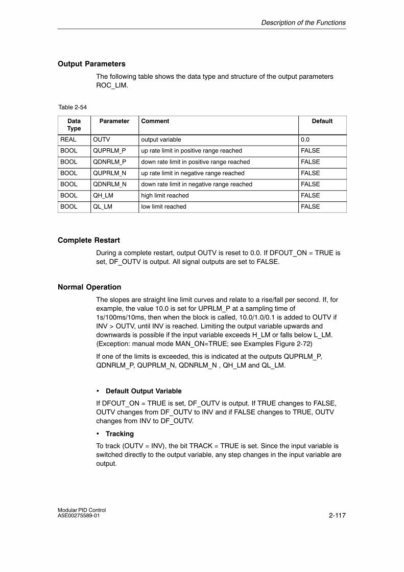
Description of the Functions
2-117Modular PID ControlA5E00275589-01
Output Parameters
The following table shows the data type and structure of the output parametersROC_LIM.
Table 2-54
DataType
Parameter Comment Default
REAL OUTV output variable 0.0
BOOL QUPRLM_P up rate limit in positive range reached FALSE
BOOL QDNRLM_P down rate limit in positive range reached FALSE
BOOL QUPRLM_N up rate limit in negative range reached FALSE
BOOL QDNRLM_N down rate limit in negative range reached FALSE
BOOL QH_LM high limit reached FALSE
BOOL QL_LM low limit reached FALSE
Complete Restart
During a complete restart, output OUTV is reset to 0.0. If DFOUT_ON = TRUE isset, DF_OUTV is output. All signal outputs are set to FALSE.
Normal Operation
The slopes are straight line limit curves and relate to a rise/fall per second. If, forexample, the value 10.0 is set for UPRLM_P at a sampling time of1s/100ms/10ms, then when the block is called, 10.0/1.0/0.1 is added to OUTV ifINV > OUTV, until INV is reached. Limiting the output variable upwards anddownwards is possible if the input variable exceeds H_LM or falls below L_LM.(Exception: manual mode MAN_ON=TRUE; see Examples Figure 2-72)
If one of the limits is exceeded, this is indicated at the outputs QUPRLM_P,QDNRLM_P, QUPRLM_N, QDNRLM_N , QH_LM and QL_LM.
• Default Output Variable
If DFOUT_ON = TRUE is set, DF_OUTV is output. If TRUE changes to FALSE,OUTV changes from DF_OUTV to INV and if FALSE changes to TRUE, OUTVchanges from INV to DF_OUTV.
• Tracking
To track (OUTV = INV), the bit TRACK = TRUE is set. Since the input variable isswitched directly to the output variable, any step changes in the input variable areoutput.
Description of the Functions
2-118Modular PID Control
A5E00275589-01
• Stepless Manual-Automatic Switchover
For this mode, the ramp block must be included in the setpoint branch directlybefore the error signal. The process variable is connected to the input PV and themanual-automatic bit to input MAN_ON. When you change to the manual modeMAN_ON = TRUE, the value at input PV is switched immediately to the outputOUTV. Since the setpoint and process variable are the same, the error signalbecomes zero and the controller is in a stationary settled state. When you return tothe automatic mode MAN_ON = FALSE, the ramp function ensures a gradualchange in the output OUTV from the current value PV to the input value INV. Thisresults in a stepless switchover from the manual to the automatic mode (seeFigure 2-72)
The default output variable mode has lower priority if MAN_ON=TRUE is set and isignored.
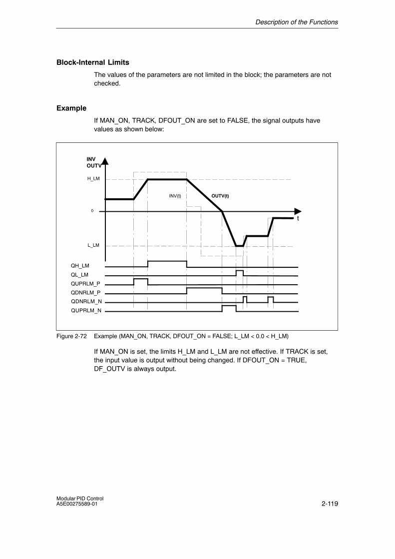
Description of the Functions
2-119Modular PID ControlA5E00275589-01
Block-Internal Limits
The values of the parameters are not limited in the block; the parameters are notchecked.
Example
If MAN_ON, TRACK, DFOUT_ON are set to FALSE, the signal outputs havevalues as shown below:
H_LM
0
QH_LM
QL_LM
QUPRLM_P
QDNRLM_P
QDNRLM_N
QUPRLM_N
INV(t) OUTV(t)
L_LM
t
INVOUTV
Figure 2-72 Example (MAN_ON, TRACK, DFOUT_ON = FALSE; L_LM < 0.0 < H_LM)
If MAN_ON is set, the limits H_LM and L_LM are not effective. If TRACK is set,the input value is output without being changed. If DFOUT_ON = TRUE,DF_OUTV is always output.
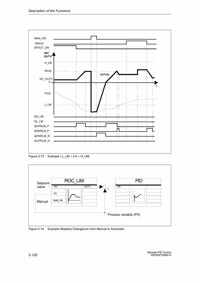
Description of the Functions
2-120Modular PID Control
A5E00275589-01
QH_LM
QL_LM
QUPRLM_P
QDNRLM_P
QDNRLM_N
QUPRLM_N
H_LM
INV(t)
DF_OUTV
PV(t)
L_LM
MAN_ON
TRACK
DFOUT_ON
OUTV(t)
t
INVOUTV
0
Figure 2-73 Example ( L_LM < 0.0 < H_LM)
ROC_LIM PID
PV
INV
MAN_ON
�ER
Process variable (PV)
OUTVSetpoint value
Manual
Figure 2-74 Example Stepless Changeover from Manual to Automatic

Description of the Functions
2-121Modular PID ControlA5E00275589-01
Example of a ramp used only in the positive range
Input Parameters
The following table shows the data type and structure of the input parameters.
Table 2-55 Input Parameters
Data Type Parameter Comment Parameter Assignment
REAL INV input variable 0.0
REAL UPRLM_P up rate limit in positive range 10.0
REAL DNRLM_P down rate limit in positive range 5.0
REAL UPRLM_N up rate limit in negative range 0.0
REAL DNRLM_N down rate limit in negative range 0.0
REAL H_LM high limit 85.5
REAL L_LM low limit 27.0
REAL PV process variable 0.0
REAL DF_OUTV default output variable 46.15
BOOL DFOUT_ON default output variable on FALSE
BOOL TRACK tracking OUTV = INV FALSE
BOOL MAN_ON manual mode on FALSE
BOOL COM_RST complete restart FALSE
TIME CYCLE sampling time T#1s
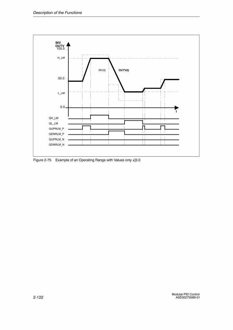
Description of the Functions
2-122Modular PID Control
A5E00275589-01
0.0
QH_LM
QL_LM
QUPRLM_P
QDNRLM_P
QUPRLM_N
QDNRLM_N
INV(t) OUTV(t)
H_LM
L_LM
t
INVOUTV100.0
50.0
Figure 2-75 Example of an Operating Range with Values only ≥.0.0
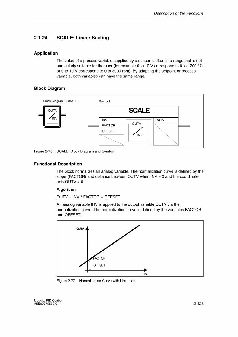
Description of the Functions
2-123Modular PID ControlA5E00275589-01
2.1.24 SCALE: Linear Scaling
Application
The value of a process variable supplied by a sensor is often in a range that is notparticularly suitable for the user (for example 0 to 10 V correspond to 0 to 1200 �Cor 0 to 10 V correspond to 0 to 3000 rpm). By adapting the setpoint or processvariable, both variables can have the same range.
Block Diagram
: SCALE Symbol:
SCALEINV
OUTV
INV
OUTVINV OUTV
FACTOR
OFFSET
Block Diagram
Figure 2-76 SCALE, Block Diagram and Symbol
Functional Description
The block normalizes an analog variable. The normalization curve is defined by theslope (FACTOR) and distance between OUTV when INV = 0 and the coordinateaxis OUTV = 0.
Algorithm
OUTV = INV * FACTOR + OFFSET
An analog variable INV is applied to the output variable OUTV via thenormalization curve. The normalization curve is defined by the variables FACTORand OFFSET.
INV
OUTV
OFFSET
FACTOR
Figure 2-77 Normalization Curve with Limitation
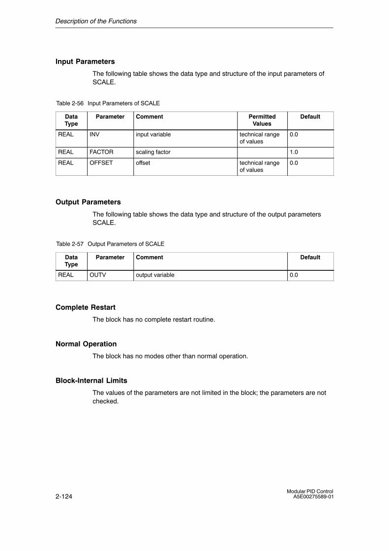
Description of the Functions
2-124Modular PID Control
A5E00275589-01
Input Parameters
The following table shows the data type and structure of the input parameters ofSCALE.
Table 2-56 Input Parameters of SCALE
DataType
Parameter Comment PermittedValues
Default
REAL INV input variable technical rangeof values
0.0
REAL FACTOR scaling factor 1.0
REAL OFFSET offset technical rangeof values
0.0
Output Parameters
The following table shows the data type and structure of the output parametersSCALE.
Table 2-57 Output Parameters of SCALE
DataType
Parameter Comment Default
REAL OUTV output variable 0.0
Complete Restart
The block has no complete restart routine.
Normal Operation
The block has no modes other than normal operation.
Block-Internal Limits
The values of the parameters are not limited in the block; the parameters are notchecked.
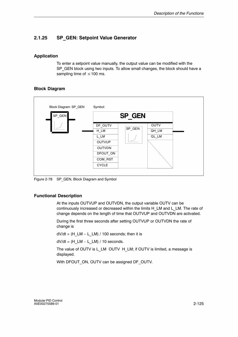
Description of the Functions
2-125Modular PID ControlA5E00275589-01
2.1.25 SP_GEN: Setpoint Value Generator
Application
To enter a setpoint value manually, the output value can be modified with theSP_GEN block using two inputs. To allow small changes, the block should have asampling time of �100 ms.
Block Diagram
Symbol:
SP_GENSP_GEN
SP_GENOUTV
L_LM
H_LM
QL_LM
QH_LM
OUTVDN
OUTVUP
DFOUT_ON
DF_OUTV
COM_RST
CYCLE
Block Diagram: SP_GEN
Figure 2-78 SP_GEN, Block Diagram and Symbol
Functional Description
At the inputs OUTVUP and OUTVDN, the output variable OUTV can becontinuously increased or decreased within the limits H_LM and L_LM. The rate ofchange depends on the length of time that OUTVUP and OUTVDN are activated.
During the first three seconds after setting OUTVUP or OUTVDN the rate ofchange is
dV/dt = (H_LM � L_LM) / 100 seconds; then it is
dV/dt = (H_LM � L_LM) / 10 seconds.
The value of OUTV is L_LM OUTV H_LM; if OUTV is limited, a message isdisplayed.
With DFOUT_ON, OUTV can be assigned DF_OUTV.
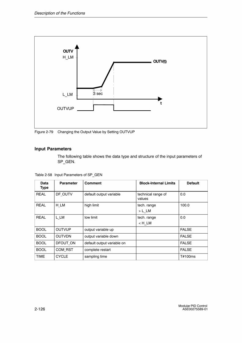
Description of the Functions
2-126Modular PID Control
A5E00275589-01
OUTV
t
H_LM
L_LM
OUTVUP
3 sec
OUTV(t)
Figure 2-79 Changing the Output Value by Setting OUTVUP
Input Parameters
The following table shows the data type and structure of the input parameters ofSP_GEN.
Table 2-58 Input Parameters of SP_GEN
DataType
Parameter Comment Block-Internal Limits Default
REAL DF_OUTV default output variable technical range ofvalues
0.0
REAL H_LM high limit tech. range
> L_LM
100.0
REAL L_LM low limit tech. range
< H_LM
0.0
BOOL OUTVUP output variable up FALSE
BOOL OUTVDN output variable down FALSE
BOOL DFOUT_ON default output variable on FALSE
BOOL COM_RST complete restart FALSE
TIME CYCLE sampling time T#100ms
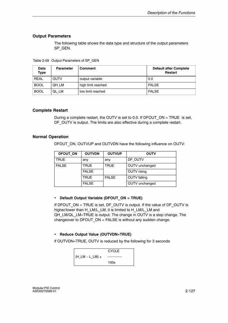
Description of the Functions
2-127Modular PID ControlA5E00275589-01
Output Parameters
The following table shows the data type and structure of the output parametersSP_GEN.
Table 2-59 Output Parameters of SP_GEN
DataType
Parameter Comment Default after CompleteRestart
REAL OUTV output variable 0.0
BOOL QH_LM high limit reached FALSE
BOOL QL_LM low limit reached FALSE
Complete Restart
During a complete restart, the OUTV is set to 0.0. If DFOUT_ON = TRUE is set,DF_OUTV is output. The limits are also effective during a complete restart.
Normal Operation
DFOUT_ON, OUTVUP and OUTVDN have the following influence on OUTV:
DFOUT_ON OUTVDN OUTVUP OUTV
TRUE any any DF_OUTV
FALSE TRUE TRUE OUTV unchanged
FALSE OUTV rising
TRUE FALSE OUTV falling
FALSE OUTV unchanged
• Default Output Variable (DFOUT_ON = TRUE)
If DFOUT_ON = TRUE is set, DF_OUTV is output. If the value of DF_OUTV ishigher/lower than H_LM/L_LM, it is limited to H_LM/L_LM andQH_LM/QL_LM=TRUE is output. The change in OUTV is a step change. Thechangeover to DFOUT_ON = FALSE is without any sudden change.
• Reduce Output Value (OUTVDN=TRUE)
if OUTVDN=TRUE, OUTV is reduced by the following for 3 seconds
CYCLE
(H_LM � L_LM) �
100s
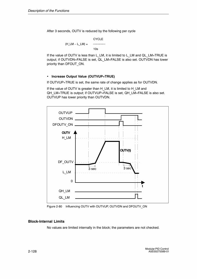
Description of the Functions
2-128Modular PID Control
A5E00275589-01
After 3 seconds, OUTV is reduced by the following per cycle
CYCLE
(H_LM � L_LM) �
10s
If the value of OUTV is less than L_LM, it is limited to L_LM and QL_LM=TRUE isoutput; if OUTVDN=FALSE is set, QL_LM=FALSE is also set. OUTVDN has lowerpriority than DFOUT_ON.
• Increase Output Value (OUTVUP=TRUE)
If OUTVUP=TRUE is set, the same rate of change applies as for OUTVDN.
If the value of OUTV is greater than H_LM, it is limited to H_LM andQH_LM=TRUE is output; if OUTVUP=FALSE is set, QH_LM=FALSE is also set.OUTVUP has lower priority than OUTVDN.
OUTV
t
H_LM
L_LM
OUTVUP
3 sec
OUTV(t)
DF_OUTV
3 sec
DFOUTV_ON
OUTVDN
QH_LM
QL_LM
0
Figure 2-80 Influencing OUTV with OUTVUP, OUTVDN and DFOUTV_ON
Block-Internal Limits
No values are limited internally in the block; the parameters are not checked.
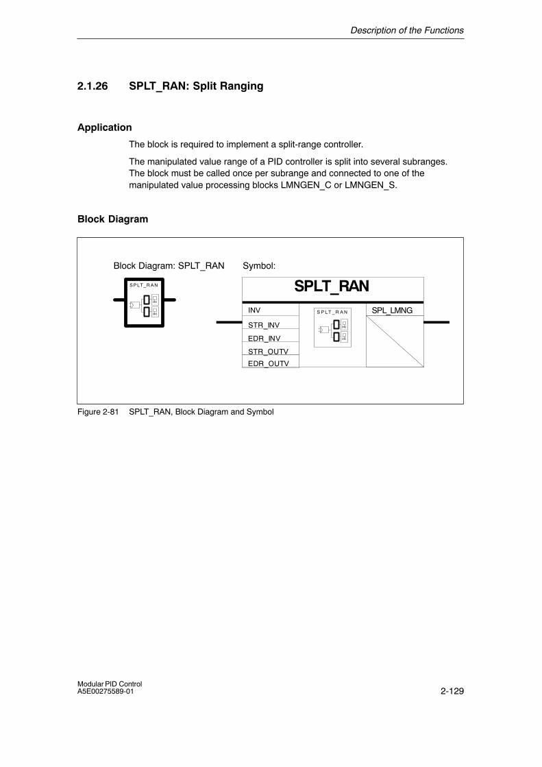
Description of the Functions
2-129Modular PID ControlA5E00275589-01
2.1.26 SPLT_RAN: Split Ranging
Application
The block is required to implement a split-range controller.
The manipulated value range of a PID controller is split into several subranges.The block must be called once per subrange and connected to one of themanipulated value processing blocks LMNGEN_C or LMNGEN_S.
Block Diagram
Symbol:
SPLT_RANS P LT_R A N
S P L T _ R A N
STR_INV
EDR_INV
STR_OUTV
EDR_OUTV
SPL_LMNG
Block Diagram: SPLT_RAN
INV
Figure 2-81 SPLT_RAN, Block Diagram and Symbol

Description of the Functions
2-130Modular PID Control
A5E00275589-01
Functional Description
An input value within a range limited by STR_INV and EDR_INV is converted to anoutput value within a range limited by STR_OUTV and EDR_OUTV (see Figure2-82).
INVEDR_INVSTR_INV
SPL_LMNG.PID_OUTV
STR_OUTV
EDR_OUTV
0
Figure 2-82

Description of the Functions
2-131Modular PID ControlA5E00275589-01
Input Parameters
The following table shows the data type and structure of the input parameters ofSPLT_RAN.
Table 2-60 Input Parameters of SPLT_RAN
DataType
Parameter Comment PermittedValues
Default
REAL INV input variable technical rangeof values
0.0
REAL STR_INV start of range INV technical rangeof values
0.0
REAL EDR_INV end of range INV technical rangeof values
50.0
REAL STR_OUTV start of range OUTV technical rangeof values
0.0
REAL EDR_OUTV end of range OUTV technical rangeof values
100.0
Output Parameters
The following table shows the data type and structure of the output parametersSPLT_RAN.
Table 2-61 Output Parameters of SPLT_RAN
DataType
Parameter Comment Default
STRUC SPL_LMNG PID-LMNGEN interface
Complete Restart
The block has no complete restart routine.
Normal Operation
The block has no modes other than normal operation.
Block-Internal Limits
The values of the parameters are not limited in the block; the parameters are notchecked.
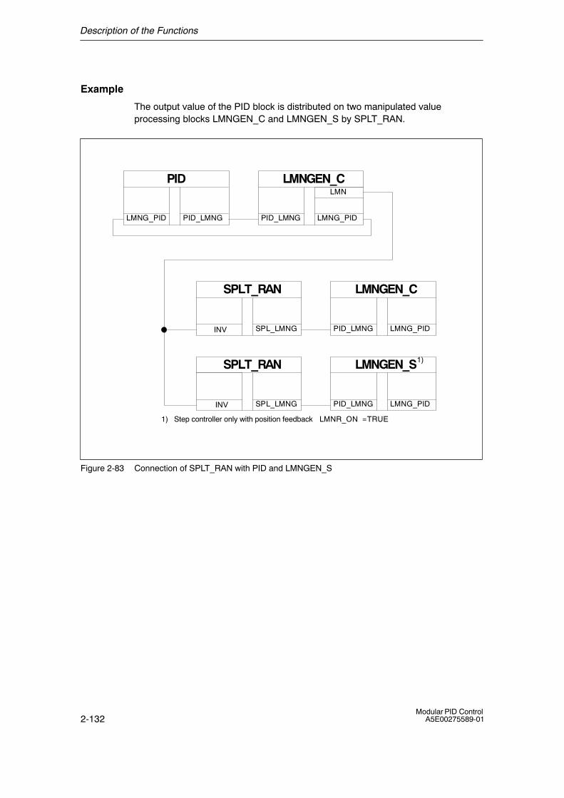
Description of the Functions
2-132Modular PID Control
A5E00275589-01
Example
The output value of the PID block is distributed on two manipulated valueprocessing blocks LMNGEN_C and LMNGEN_S by SPLT_RAN.
PID
PID_LMNGLMNG_PID
LMNGEN_C
LMNG_PIDPID_LMNG
SPLT_RAN
SPL_LMNGINV
LMNGEN_C
LMNG_PIDPID_LMNG
1) Step controller only with position feedback LMNR_ON = TRUE
LMN
SPLT_RAN
SPL_LMNGINV
LMNGEN_S
LMNG_PIDPID_LMNG
1)
Figure 2-83 Connection of SPLT_RAN with PID and LMNGEN_S
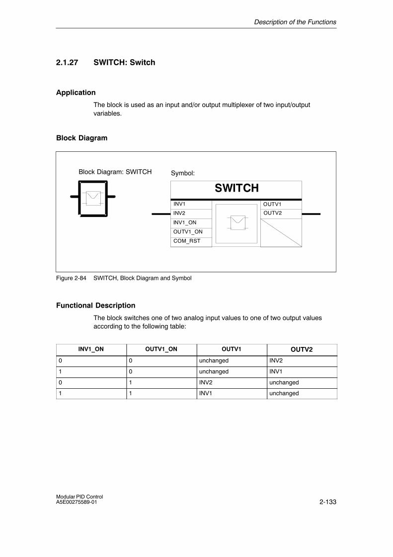
Description of the Functions
2-133Modular PID ControlA5E00275589-01
2.1.27 SWITCH: Switch
Application
The block is used as an input and/or output multiplexer of two input/outputvariables.
Block Diagram
Symbol:
SWITCHINV1
INV2
OUTV1
OUTV2
INV1_ON
OUTV1_ON
COM_RST
Block Diagram: SWITCH
Figure 2-84 SWITCH, Block Diagram and Symbol
Functional Description
The block switches one of two analog input values to one of two output valuesaccording to the following table:
INV1_ON OUTV1_ON OUTV1 OUTV2
0 0 unchanged INV2
1 0 unchanged INV1
0 1 INV2 unchanged
1 1 INV1 unchanged
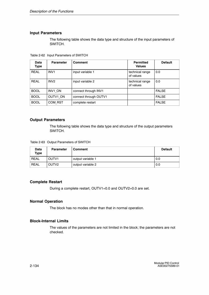
Description of the Functions
2-134Modular PID Control
A5E00275589-01
Input Parameters
The following table shows the data type and structure of the input parameters ofSWITCH.
Table 2-62 Input Parameters of SWITCH
DataType
Parameter Comment PermittedValues
Default
REAL INV1 input variable 1 technical rangeof values
0.0
REAL INV2 input variable 2 technical rangeof values
0.0
BOOL INV1_ON connect through INV1 FALSE
BOOL OUTV1_ON connect through OUTV1 FALSE
BOOL COM_RST complete restart FALSE
Output Parameters
The following table shows the data type and structure of the output parametersSWITCH.
Table 2-63 Output Parameters of SWITCH
DataType
Parameter Comment Default
REAL OUTV1 output variable 1 0.0
REAL OUTV2 output variable 2 0.0
Complete Restart
During a complete restart, OUTV1=0.0 and OUTV2=0.0 are set.
Normal Operation
The block has no modes other than that in normal operation.
Block-Internal Limits
The values of the parameters are not limited in the block; the parameters are notchecked.
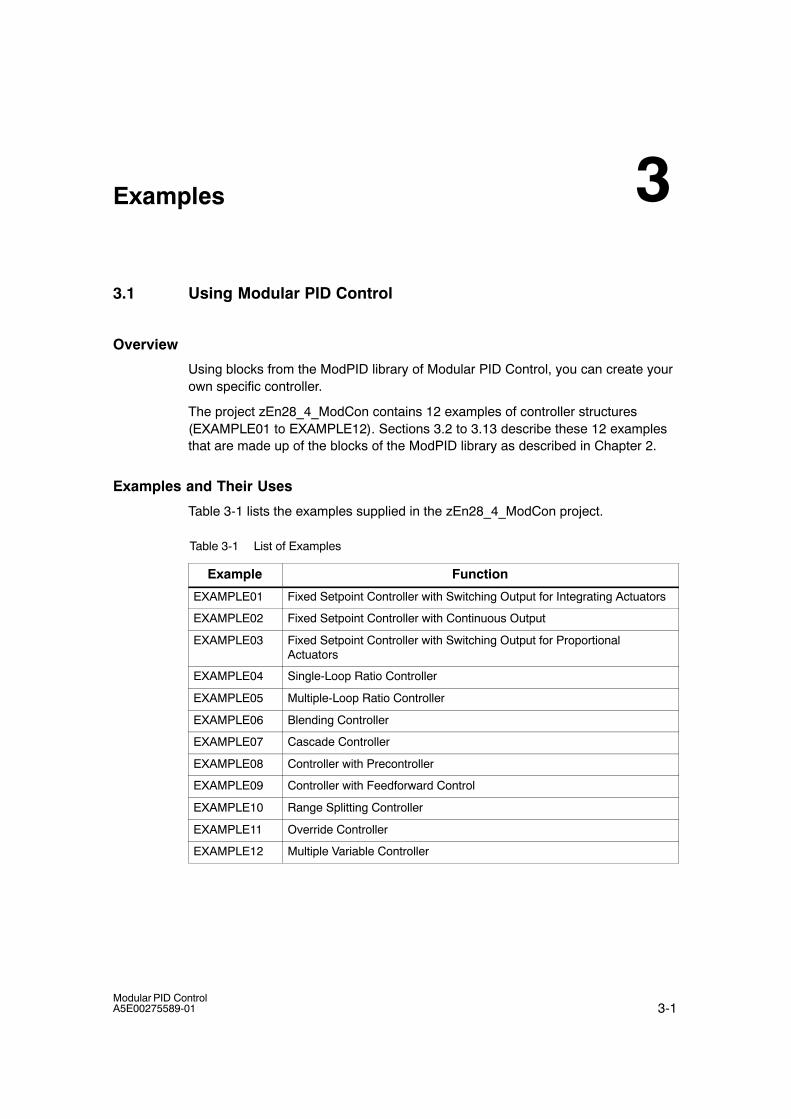
3-1Modular PID ControlA5E00275589-01
Examples
3.1 Using Modular PID Control
Overview
Using blocks from the ModPID library of Modular PID Control, you can create yourown specific controller.
The project zEn28_4_ModCon contains 12 examples of controller structures(EXAMPLE01 to EXAMPLE12). Sections 3.2 to 3.13 describe these 12 examplesthat are made up of the blocks of the ModPID library as described in Chapter 2.
Examples and Their Uses
Table 3-1 lists the examples supplied in the zEn28_4_ModCon project.
Table 3-1 List of Examples
Example Function
EXAMPLE01 Fixed Setpoint Controller with Switching Output for Integrating Actuators
EXAMPLE02 Fixed Setpoint Controller with Continuous Output
EXAMPLE03 Fixed Setpoint Controller with Switching Output for ProportionalActuators
EXAMPLE04 Single-Loop Ratio Controller
EXAMPLE05 Multiple-Loop Ratio Controller
EXAMPLE06 Blending Controller
EXAMPLE07 Cascade Controller
EXAMPLE08 Controller with Precontroller
EXAMPLE09 Controller with Feedforward Control
EXAMPLE10 Range Splitting Controller
EXAMPLE11 Override Controller
EXAMPLE12 Multiple Variable Controller
3
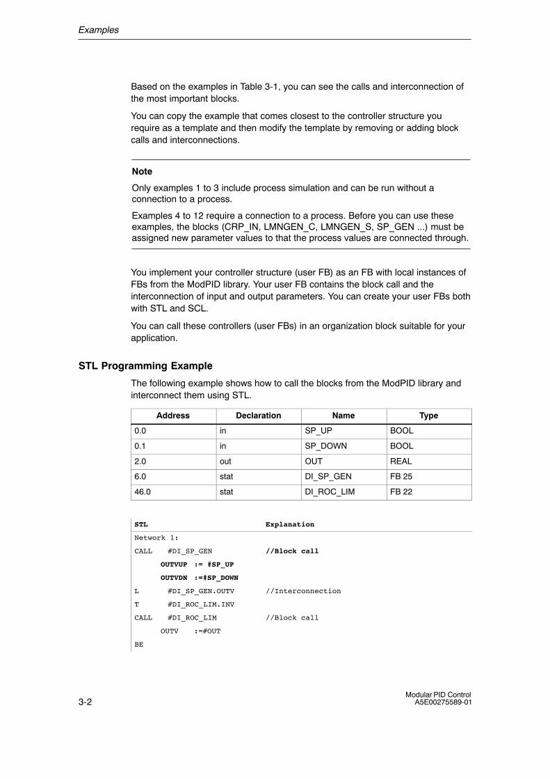
Examples
3-2Modular PID Control
A5E00275589-01
Based on the examples in Table 3-1, you can see the calls and interconnection ofthe most important blocks.
You can copy the example that comes closest to the controller structure yourequire as a template and then modify the template by removing or adding blockcalls and interconnections.
Note
Only examples 1 to 3 include process simulation and can be run without aconnection to a process.
Examples 4 to 12 require a connection to a process. Before you can use theseexamples, the blocks (CRP_IN, LMNGEN_C, LMNGEN_S, SP_GEN ...) must beassigned new parameter values to that the process values are connected through.
You implement your controller structure (user FB) as an FB with local instances ofFBs from the ModPID library. Your user FB contains the block call and theinterconnection of input and output parameters. You can create your user FBs bothwith STL and SCL.
You can call these controllers (user FBs) in an organization block suitable for yourapplication.
STL Programming Example
The following example shows how to call the blocks from the ModPID library andinterconnect them using STL.
Address Declaration Name Type
0.0 in SP_UP BOOL
0.1 in SP_DOWN BOOL
2.0 out OUT REAL
6.0 stat DI_SP_GEN FB 25
46.0 stat DI_ROC_LIM FB 22
STL Explanation
Network 1:
CALL #DI_SP_GEN //Block call
OUTVUP := #SP_UP
OUTVDN :=#SP_DOWN
L #DI_SP_GEN.OUTV //Interconnection
T #DI_ROC_LIM.INV
CALL #DI_ROC_LIM //Block call
OUTV :=#OUT
BE
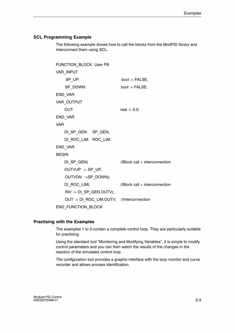
Examples
3-3Modular PID ControlA5E00275589-01
SCL Programming Example
The following example shows how to call the blocks from the ModPID library andinterconnect them using SCL.
FUNCTION_BLOCK User FB
VAR_INPUT
SP_UP: bool := FALSE;
SP_DOWN: bool := FALSE;
END_VAR
VAR_OUTPUT
OUT: real := 0.0;
END_VAR
VAR
DI_SP_GEN: SP_GEN;
DI_ROC_LIM: ROC_LIM;
END_VAR
BEGIN
DI_SP_GEN( //Block call + interconnection
OUTVUP := SP_UP,
OUTVDN :=SP_DOWN);
DI_ROC_LIM( //Block call + interconnection
INV := DI_SP_GEN.OUTV);
OUT := DI_ROC_LIM.OUTV; //Interconnection
END_FUNCTION_BLOCK
Practising with the Examples
The examples 1 to 3 contain a complete control loop. They are particularly suitablefor practising.
Using the standard tool �Monitoring and Modifying Variables�, it is simple to modifycontrol parameters and you can then watch the results of the changes in thereaction of the simulated control loop.
The configuration tool provides a graphic interface with the loop monitor and curverecorder and allows process identification.
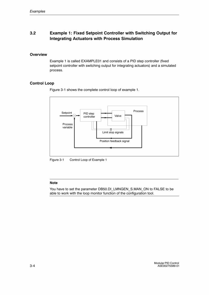
Examples
3-4Modular PID Control
A5E00275589-01
3.2 Example 1: Fixed Setpoint Controller with Switching Output forIntegrating Actuators with Process Simulation
Overview
Example 1 is called EXAMPLE01 and consists of a PID step controller (fixedsetpoint controller with switching output for integrating actuators) and a simulatedprocess.
Control Loop
Figure 3-1 shows the complete control loop of example 1.
�PID stepcontroller
ProcessSetpoint
Process variable
Valve
Limit stop signals
Position feedback signal
Figure 3-1 Control Loop of Example 1
Note
You have to set the parameter DB50.DI_LMNGEN_S.MAN_ON to FALSE to beable to work with the loop monitor function of the configuration tool.
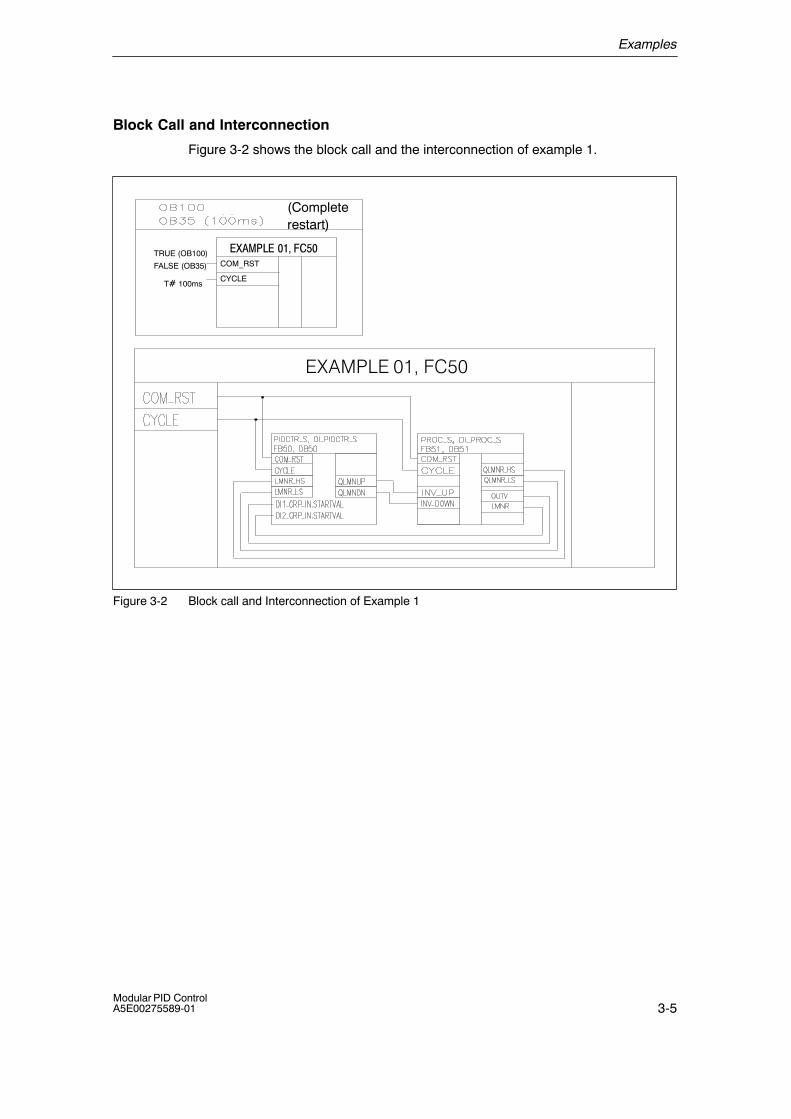
Examples
3-5Modular PID ControlA5E00275589-01
Block Call and Interconnection
Figure 3-2 shows the block call and the interconnection of example 1.
TRUE (OB100)
FALSE (OB35)
T� 100ms
COM_RST
CYCLE
(Completerestart)
������������ �
�E�������7��(
Figure 3-2 Block call and Interconnection of Example 1
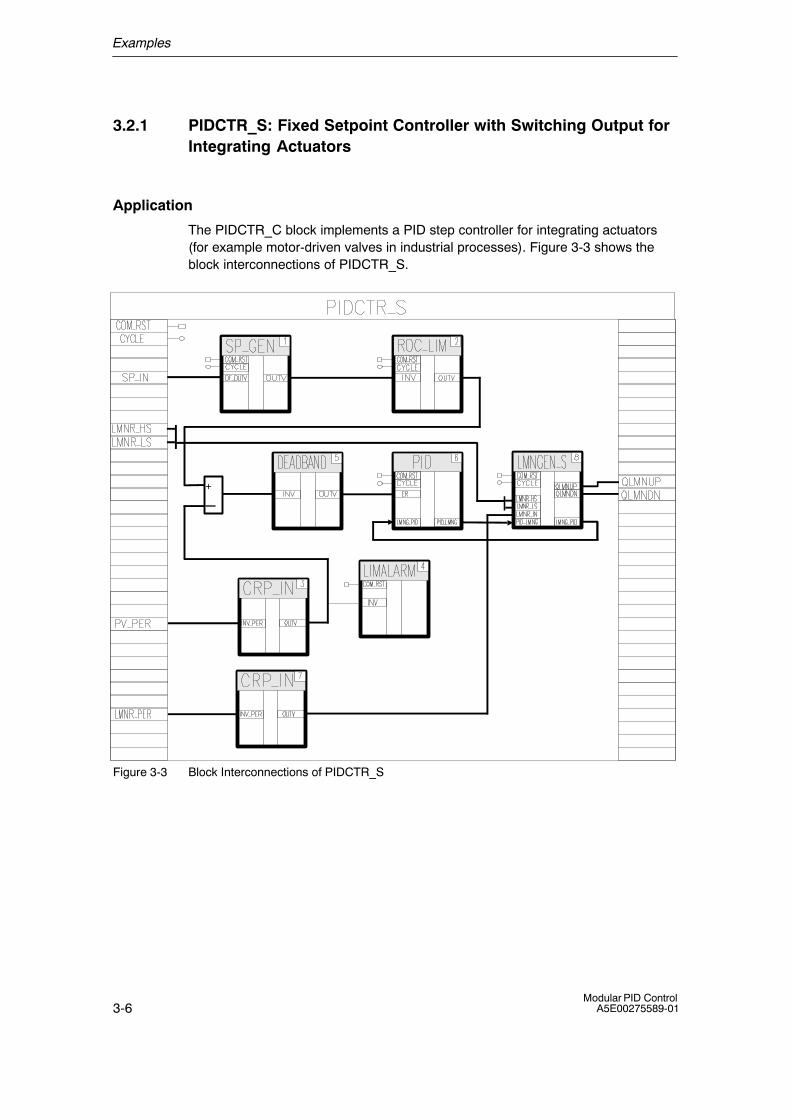
Examples
3-6Modular PID Control
A5E00275589-01
3.2.1 PIDCTR_S: Fixed Setpoint Controller with Switching Output forIntegrating Actuators
Application
The PIDCTR_C block implements a PID step controller for integrating actuators(for example motor-driven valves in industrial processes). Figure 3-3 shows theblock interconnections of PIDCTR_S.
+
�
Figure 3-3 Block Interconnections of PIDCTR_S

Examples
3-7Modular PID ControlA5E00275589-01
Functional Description
The setpoint generator SP_GEN sets the setpoint whose rate of change is limitedby the limiter ROC_LIM. The peripheral process variable is converted to afloating-point value by CRP_IN and monitored by the limit value monitorLIMALARM to check that it does not exceed selected limit values. The error signalis routed to the PID algorithm via a DEADBAND. The position feedback signal isread in via a second CRP_IN block. The manipulated value processing blockLMNGEN_S sets the output signals QLMNUP and QLMNDN.
Complete Restart
During a complete restart, each block is called individually. Blocks with a completerestart routine run through this routine.
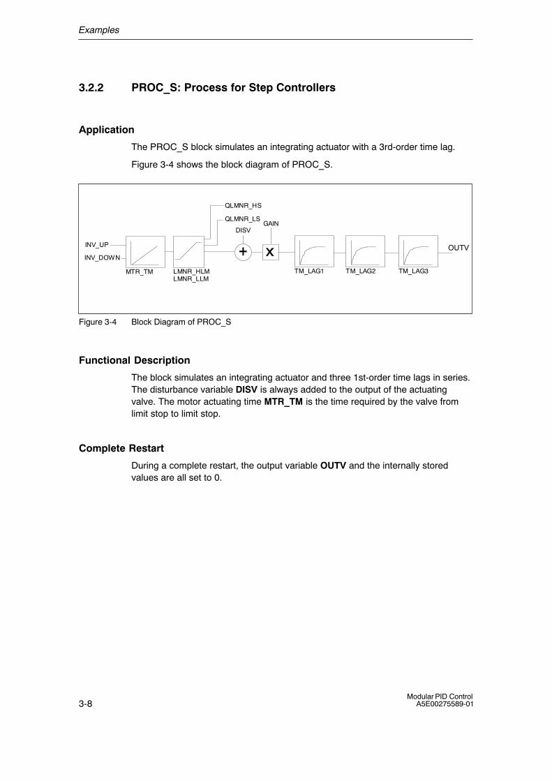
Examples
3-8Modular PID Control
A5E00275589-01
3.2.2 PROC_S: Process for Step Controllers
Application
The PROC_S block simulates an integrating actuator with a 3rd-order time lag.
Figure 3-4 shows the block diagram of PROC_S.
TM_LAG1 TM_LAG2
GAIN
OUTV
DISV
TM_LAG3MTR_TM LMNR_HLMLMNR_LLM
QLMNR_HS
QLMNR_LS
INV_UP
INV_DOWN
Figure 3-4 Block Diagram of PROC_S
Functional Description
The block simulates an integrating actuator and three 1st-order time lags in series.The disturbance variable DISV is always added to the output of the actuatingvalve. The motor actuating time MTR_TM is the time required by the valve fromlimit stop to limit stop.
Complete Restart
During a complete restart, the output variable OUTV and the internally storedvalues are all set to 0.
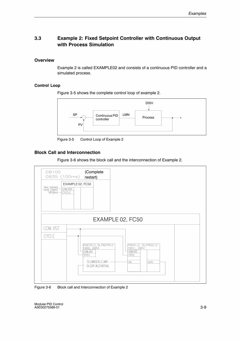
Examples
3-9Modular PID ControlA5E00275589-01
3.3 Example 2: Fixed Setpoint Controller with Continuous Outputwith Process Simulation
Overview
Example 2 is called EXAMPLE02 and consists of a continuous PID controller and asimulated process.
Control Loop
Figure 3-5 shows the complete control loop of example 2.
Continuous PIDcontroller Process
LMN
DISV
SP
PV
Figure 3-5 Control Loop of Example 2
Block Call and Interconnection
Figure 3-6 shows the block call and the interconnection of Example 2.
(Completerestart)
������������� �
������������� �
Figure 3-6 Block call and Interconnection of Example 2
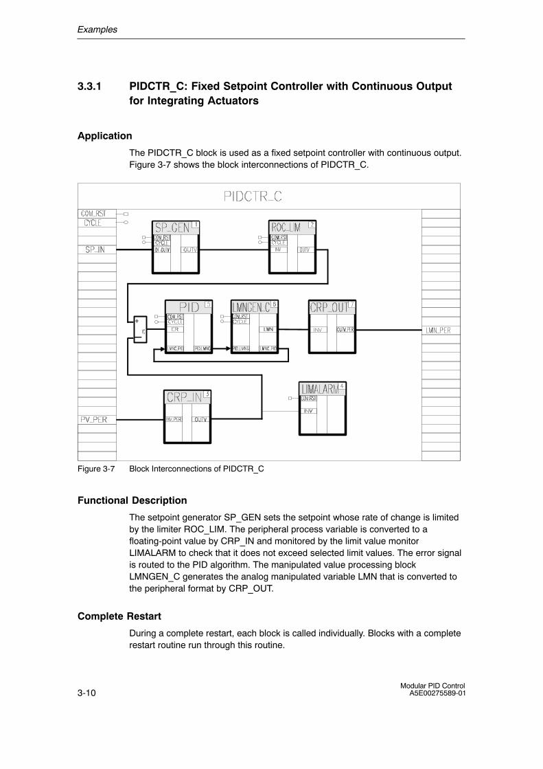
Examples
3-10Modular PID Control
A5E00275589-01
3.3.1 PIDCTR_C: Fixed Setpoint Controller with Continuous Outputfor Integrating Actuators
Application
The PIDCTR_C block is used as a fixed setpoint controller with continuous output.Figure 3-7 shows the block interconnections of PIDCTR_C.
+
�
Figure 3-7 Block Interconnections of PIDCTR_C
Functional Description
The setpoint generator SP_GEN sets the setpoint whose rate of change is limitedby the limiter ROC_LIM. The peripheral process variable is converted to afloating-point value by CRP_IN and monitored by the limit value monitorLIMALARM to check that it does not exceed selected limit values. The error signalis routed to the PID algorithm. The manipulated value processing blockLMNGEN_C generates the analog manipulated variable LMN that is converted tothe peripheral format by CRP_OUT.
Complete Restart
During a complete restart, each block is called individually. Blocks with a completerestart routine run through this routine.
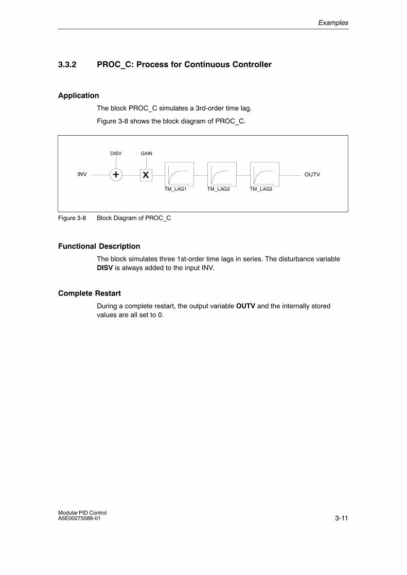
Examples
3-11Modular PID ControlA5E00275589-01
3.3.2 PROC_C: Process for Continuous Controller
Application
The block PROC_C simulates a 3rd-order time lag.
Figure 3-8 shows the block diagram of PROC_C.
TM_LAG1 TM_LAG2
GAIN
INV OUTV
DISV
TM_LAG3
Figure 3-8 Block Diagram of PROC_C
Functional Description
The block simulates three 1st-order time lags in series. The disturbance variableDISV is always added to the input INV.
Complete Restart
During a complete restart, the output variable OUTV and the internally storedvalues are all set to 0.
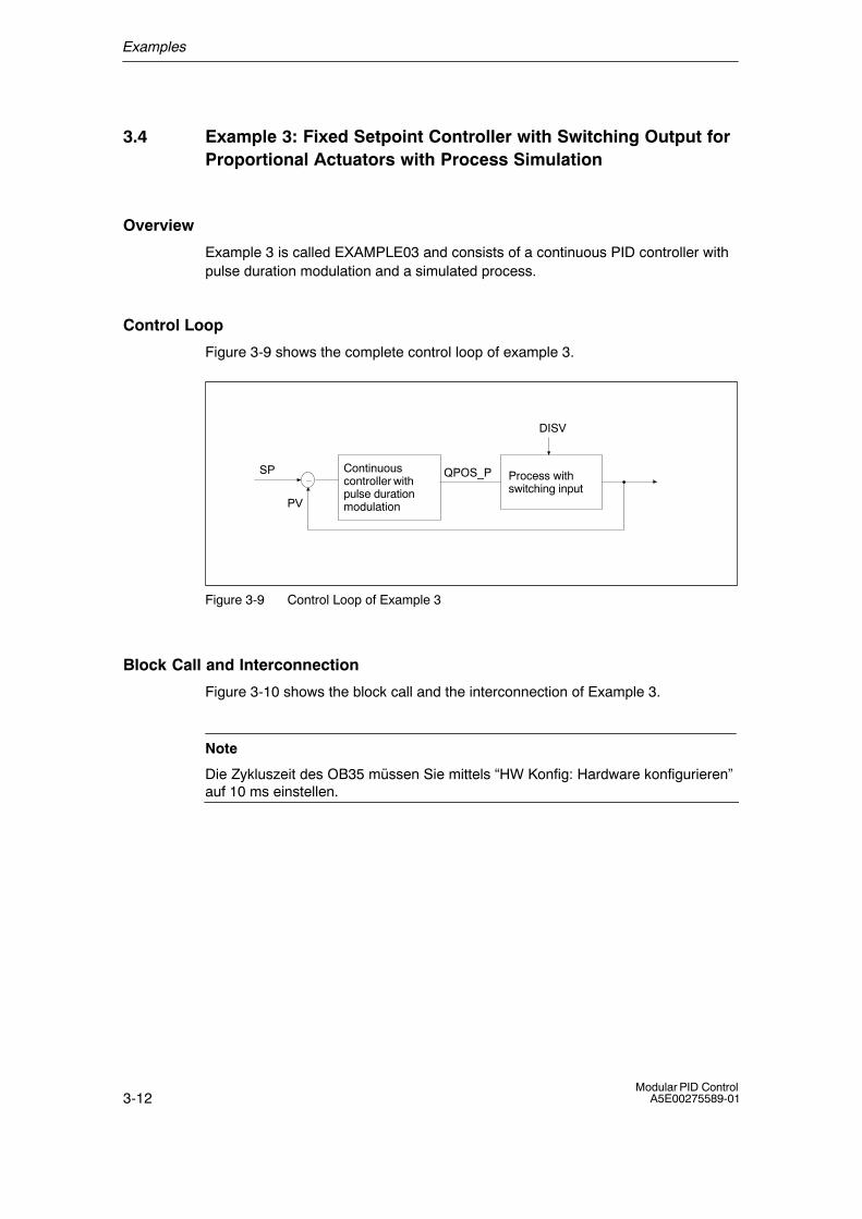
Examples
3-12Modular PID Control
A5E00275589-01
3.4 Example 3: Fixed Setpoint Controller with Switching Output forProportional Actuators with Process Simulation
Overview
Example 3 is called EXAMPLE03 and consists of a continuous PID controller withpulse duration modulation and a simulated process.
Control Loop
Figure 3-9 shows the complete control loop of example 3.
Continuouscontroller withpulse durationmodulation
QPOS_P
DISV
Process withswitching input
SP
PV
Figure 3-9 Control Loop of Example 3
Block Call and Interconnection
Figure 3-10 shows the block call and the interconnection of Example 3.
Note
Die Zykluszeit des OB35 müssen Sie mittels �HW Konfig: Hardware konfigurieren�auf 10 ms einstellen.
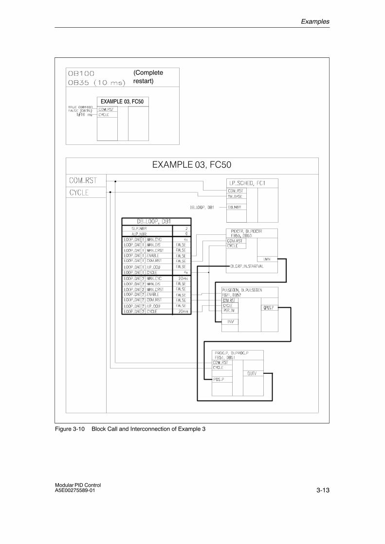
Examples
3-13Modular PID ControlA5E00275589-01
(Completerestart)
�E������'7��(
������������� �
Figure 3-10 Block Call and Interconnection of Example 3
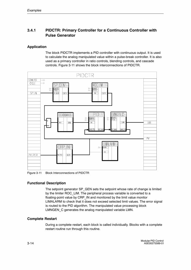
Examples
3-14Modular PID Control
A5E00275589-01
3.4.1 PIDCTR: Primary Controller for a Continuous Controller withPulse Generator
Application
The block PIDCTR implements a PID controller with continuous output. It is usedto calculate the analog manipulated value within a pulse-break controller. It is alsoused as a primary controller in ratio controls, blending controls, and cascadecontrols. Figure 3-11 shows the block interconnections of PIDCTR.
+
�
Figure 3-11 Block Interconnections of PIDCTR
Functional Description
The setpoint generator SP_GEN sets the setpoint whose rate of change is limitedby the limiter ROC_LIM. The peripheral process variable is converted to afloating-point value by CRP_IN and monitored by the limit value monitorLIMALARM to check that it does not exceed selected limit values. The error signalis routed to the PID algorithm. The manipulated value processing blockLMNGEN_C generates the analog manipulated variable LMN.
Complete Restart
During a complete restart, each block is called individually. Blocks with a completerestart routine run through this routine.
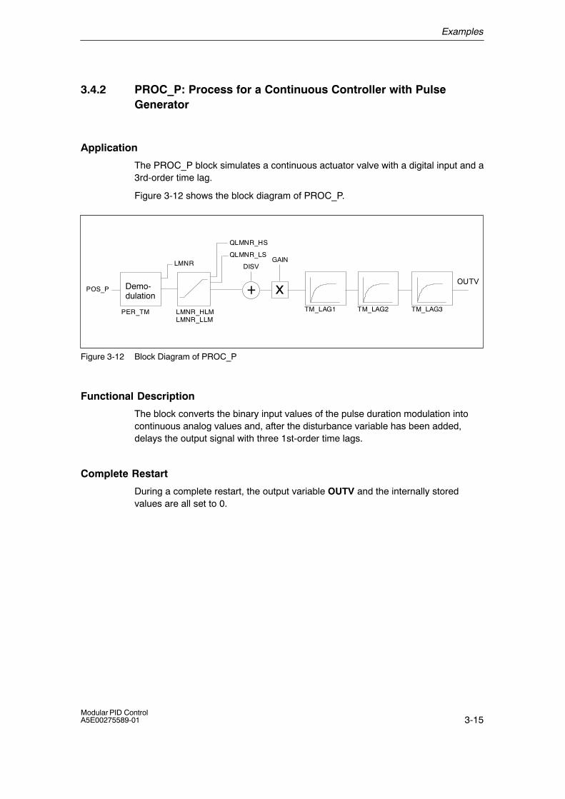
Examples
3-15Modular PID ControlA5E00275589-01
3.4.2 PROC_P: Process for a Continuous Controller with PulseGenerator
Application
The PROC_P block simulates a continuous actuator valve with a digital input and a3rd-order time lag.
Figure 3-12 shows the block diagram of PROC_P.
TM_LAG1 TM_LAG2
x
GAIN
+OUTV
DISV
TM_LAG3LMNR_HLMLMNR_LLM
QLMNR_HS
QLMNR_LS
POS_P
PER_TM
LMNR
Demo-dulation
Figure 3-12 Block Diagram of PROC_P
Functional Description
The block converts the binary input values of the pulse duration modulation intocontinuous analog values and, after the disturbance variable has been added,delays the output signal with three 1st-order time lags.
Complete Restart
During a complete restart, the output variable OUTV and the internally storedvalues are all set to 0.
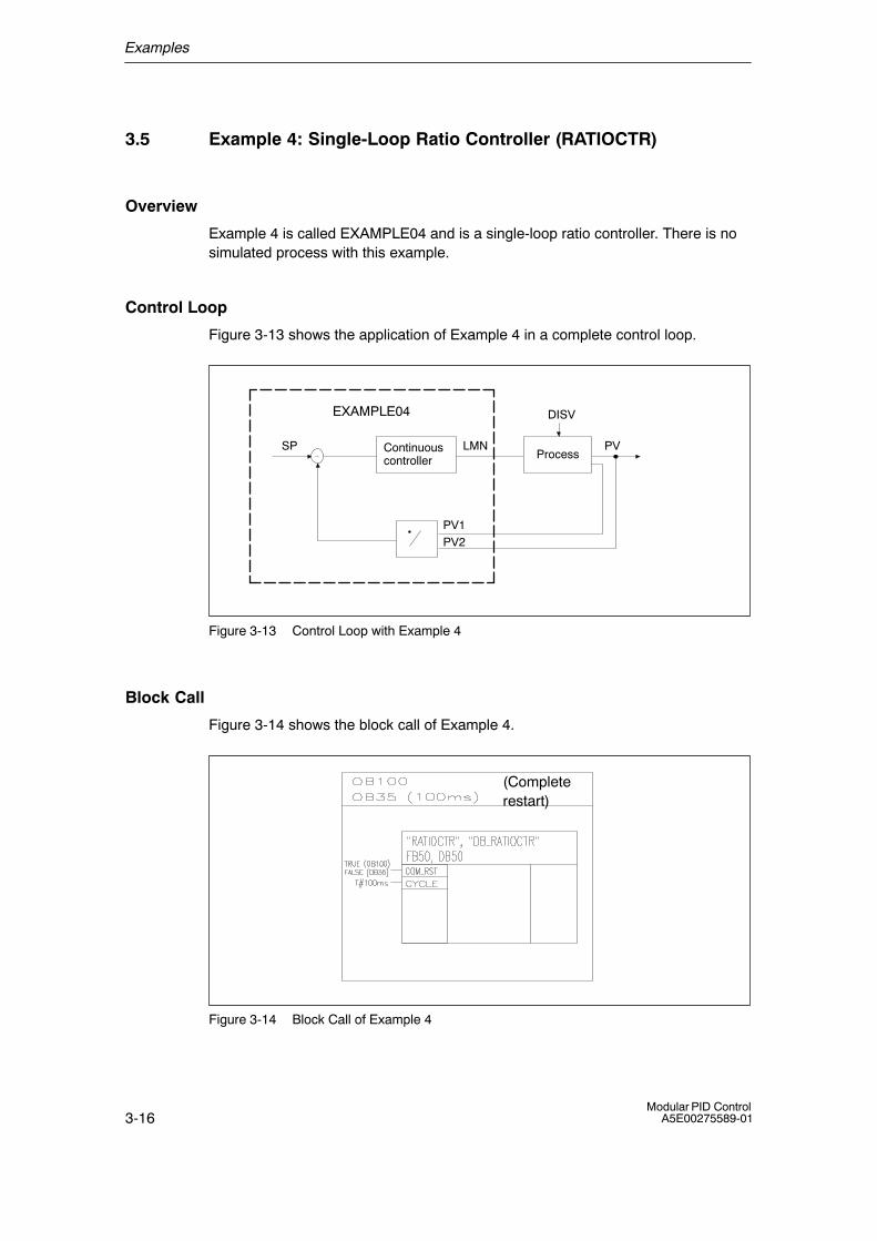
Examples
3-16Modular PID Control
A5E00275589-01
3.5 Example 4: Single-Loop Ratio Controller (RATIOCTR)
Overview
Example 4 is called EXAMPLE04 and is a single-loop ratio controller. There is nosimulated process with this example.
Control Loop
Figure 3-13 shows the application of Example 4 in a complete control loop.
EXAMPLE04
ProcessContinuouscontroller
DISV
PVSP
PV1PV2
LMN
Figure 3-13 Control Loop with Example 4
Block Call
Figure 3-14 shows the block call of Example 4.
(Completerestart)
Figure 3-14 Block Call of Example 4

Examples
3-17Modular PID ControlA5E00275589-01
Application
The block implements a single loop ratio controller for continuous actuators. Figure3-15 shows the block interconnections of RATIOCTR.
Figure 3-15 Block Interconnections of RATIOCTR
Functional Description
The ratio setpoint is set with the input parameter SP_RATIO. The peripheralprocess variables PV_PER1 and PV_PER2 are converted to floating-point valuesby CRP_IN and the ratio is formed. The floating-point value of PV_PER2 is limitedby the LIMITER so that no division by zero is possible. The error signal is routed tothe PID algorithm PID. The manipulated value processing block LMNGEN_Cgenerates the analog manipulated variable LMN that is converted to the peripheralformat by CRP_OUT.
Complete Restart
During a complete restart, each block is called individually. Blocks with a completerestart routine run through this routine.
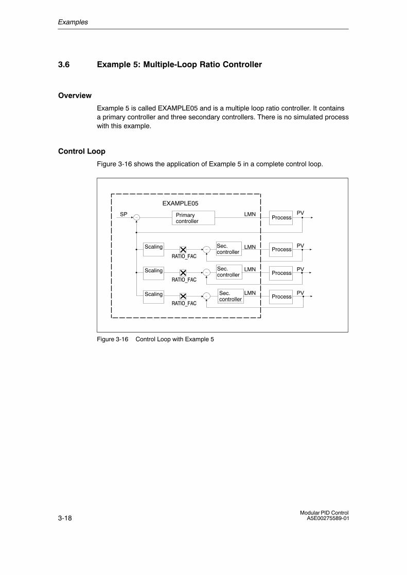
Examples
3-18Modular PID Control
A5E00275589-01
3.6 Example 5: Multiple-Loop Ratio Controller
Overview
Example 5 is called EXAMPLE05 and is a multiple loop ratio controller. It containsa primary controller and three secondary controllers. There is no simulated processwith this example.
Control Loop
Figure 3-16 shows the application of Example 5 in a complete control loop.
EXAMPLE05
Process
Process
Process
Process
PV
PV
PV
PV
LMN
LMN
LMN
LMNSec.controller
Sec.controller
Primarycontroller
Scaling
Scaling
Scaling
SP
��������
��������
��������
Sec.controller
Sec.controller
Figure 3-16 Control Loop with Example 5
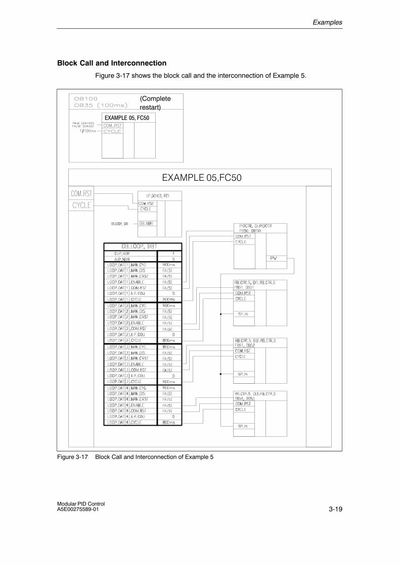
Examples
3-19Modular PID ControlA5E00275589-01
Block Call and Interconnection
Figure 3-17 shows the block call and the interconnection of Example 5.
(Completerestart)
��������� �� �
�E������(7��(
Figure 3-17 Block Call and Interconnection of Example 5
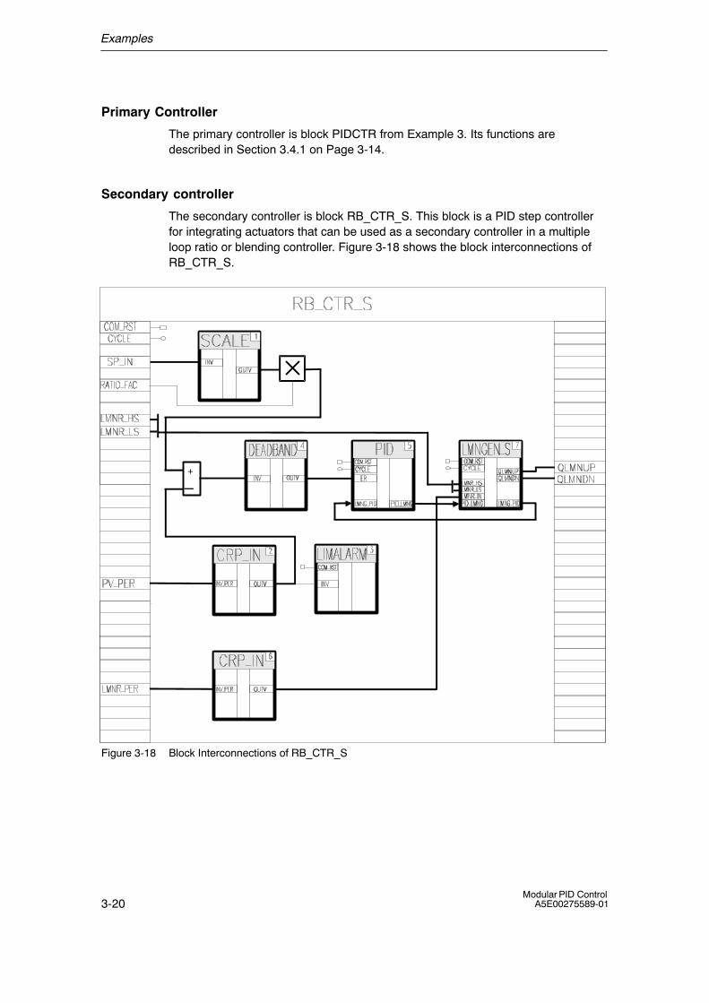
Examples
3-20Modular PID Control
A5E00275589-01
Primary Controller
The primary controller is block PIDCTR from Example 3. Its functions aredescribed in Section 3.4.1 on Page 3-14.
Secondary controller
The secondary controller is block RB_CTR_S. This block is a PID step controllerfor integrating actuators that can be used as a secondary controller in a multipleloop ratio or blending controller. Figure 3-18 shows the block interconnections ofRB_CTR_S.
+
�
Figure 3-18 Block Interconnections of RB_CTR_S
Examples
3-21Modular PID ControlA5E00275589-01
Functional Description of the Secondary controllers
The functionality of the secondary controller RB_CTR_S is analogous to that of thestep controller PIDCTR_S from Example 1 (see page 3-4). The input of thesecondary controller is adapted to the output of the process by a scaling factor andmultiplied by selected ratio or blending factor.
Complete Restart
During a complete restart, each block is called individually. Blocks with a completerestart routine run through this routine.
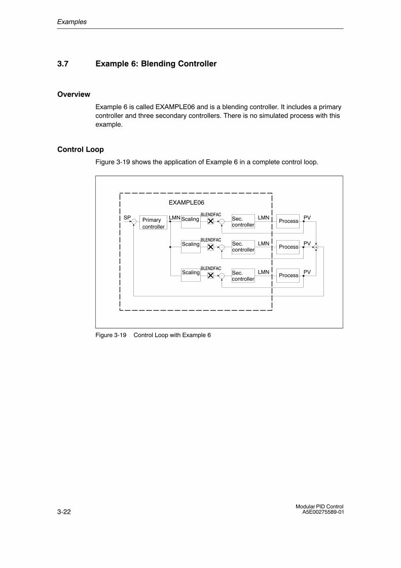
Examples
3-22Modular PID Control
A5E00275589-01
3.7 Example 6: Blending Controller
Overview
Example 6 is called EXAMPLE06 and is a blending controller. It includes a primarycontroller and three secondary controllers. There is no simulated process with thisexample.
Control Loop
Figure 3-19 shows the application of Example 6 in a complete control loop.
LMN
+
EXAMPLE06
Primarycontroller
Sec.controller
Process
Sec.controller
Sec.controller
Process
Process
�������
�������
�������
Scaling
Scaling
Scaling
PVLMNSP
PV
PV
LMN
LMN
Figure 3-19 Control Loop with Example 6
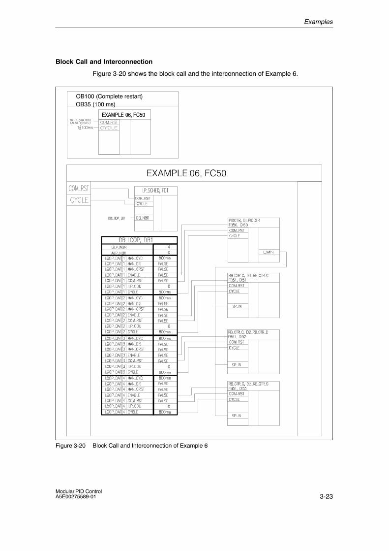
Examples
3-23Modular PID ControlA5E00275589-01
Block Call and Interconnection
Figure 3-20 shows the block call and the interconnection of Example 6.
OB100 (Complete restart)OB35 (100 ms)
�E������D7��(
������������� �
Figure 3-20 Block Call and Interconnection of Example 6

Examples
3-24Modular PID Control
A5E00275589-01
Primary controller
The primary controller is block PIDCTR from Example 3. Its functions aredescribed in Section 3.4.1 on page 3-14.
Secondary Controller
The secondary controller is block RB_CTR_C. This block is a continuous PIDcontroller that can be used as a secondary controller in a multiple loop ratio orblending controller. Figure 3-21 shows the block interconnections of RB_CTR_C.
+
�
Figure 3-21 Block Interconnections of RB_CTR_C
Functional Description of the Secondary controllers
The functionality of the secondary controller RB_CTRL_C is analogous to that ofthe continuous PID controller PIDCTR_C from Example 2 (see page 3-9). Theinput of the secondary controller is adapted to the output of the process by ascaling factor and multiplied by selected ratio or blending factor.
Complete Restart
During a complete restart, each block is called individually. Blocks with a completerestart routine run through this routine.

Examples
3-25Modular PID ControlA5E00275589-01
3.8 Example 7: Cascade Controller
Overview
Example 7 is called EXAMPLE07 and is a cascade controller. It includes a primarycontroller and a secondary controller. There is no simulated process with thisexample.
Control Loop
Figure 3-22 shows the application of Example 7 in a complete control loop.
EXAMPLE07
Primarycontroller
Sec.controller
PV1SP LMN2 PV2
DISV
LMN1Process Process
Figure 3-22 Control Loop with Example 7
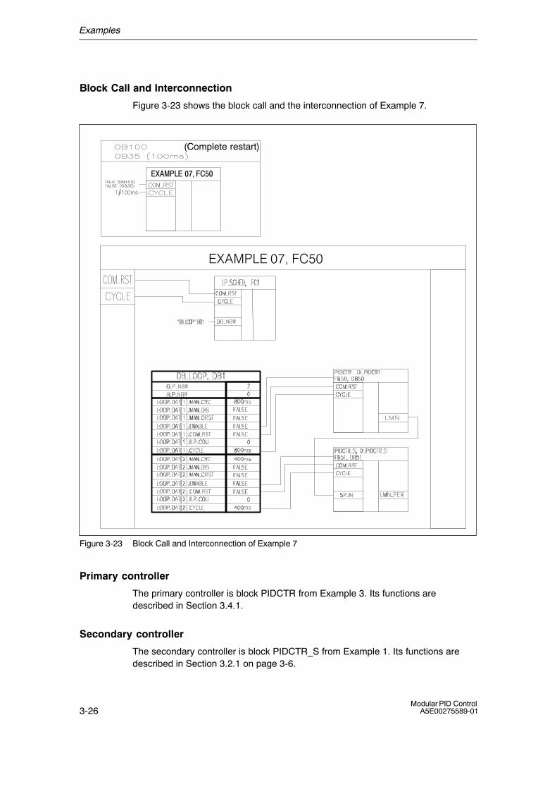
Examples
3-26Modular PID Control
A5E00275589-01
Block Call and Interconnection
Figure 3-23 shows the block call and the interconnection of Example 7.
(Complete restart)
������������� �
�E������F7��(
Figure 3-23 Block Call and Interconnection of Example 7
Primary controller
The primary controller is block PIDCTR from Example 3. Its functions aredescribed in Section 3.4.1.
Secondary controller
The secondary controller is block PIDCTR_S from Example 1. Its functions aredescribed in Section 3.2.1 on page 3-6.
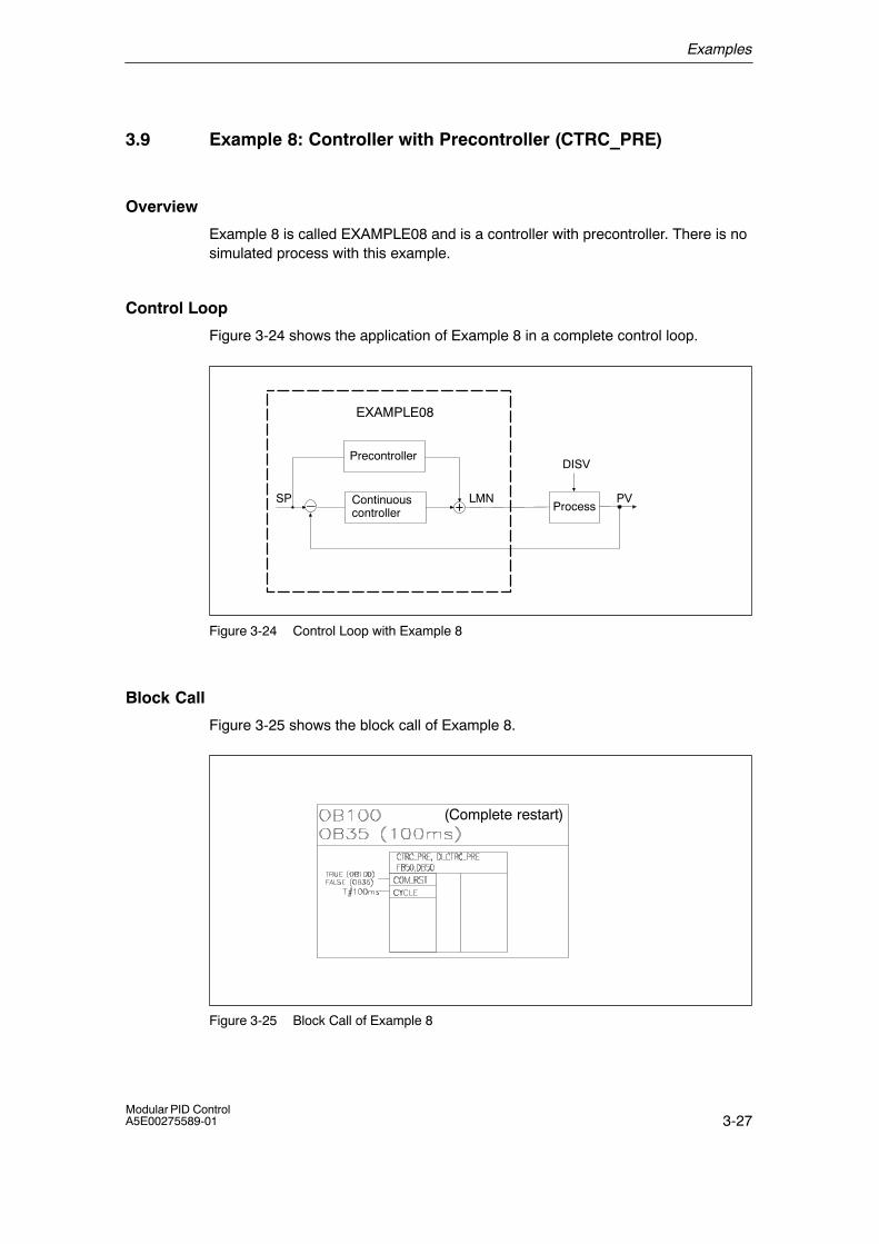
Examples
3-27Modular PID ControlA5E00275589-01
3.9 Example 8: Controller with Precontroller (CTRC_PRE)
Overview
Example 8 is called EXAMPLE08 and is a controller with precontroller. There is nosimulated process with this example.
Control Loop
Figure 3-24 shows the application of Example 8 in a complete control loop.
�
EXAMPLE08
Process
DISV
PVLMNSP
Precontroller
Continuouscontroller +
Figure 3-24 Control Loop with Example 8
Block Call
Figure 3-25 shows the block call of Example 8.
(Complete restart)
Figure 3-25 Block Call of Example 8
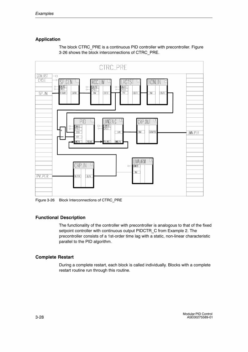
Examples
3-28Modular PID Control
A5E00275589-01
Application
The block CTRC_PRE is a continuous PID controller with precontroller. Figure3-26 shows the block interconnections of CTRC_PRE.
+
�
Figure 3-26 Block Interconnections of CTRC_PRE
Functional Description
The functionality of the controller with precontroller is analogous to that of the fixedsetpoint controller with continuous output PIDCTR_C from Example 2. Theprecontroller consists of a 1st-order time lag with a static, non-linear characteristicparallel to the PID algorithm.
Complete Restart
During a complete restart, each block is called individually. Blocks with a completerestart routine run through this routine.

Examples
3-29Modular PID ControlA5E00275589-01
3.10 Example 9: Controller with Feedforward Control (CTR_C_FF)
Overview
Example 9 is called EXAMPLE09 and is a controller with feedforward control.There is no simulated process with this example.
Control Loop
Figure 3-27 shows the application of Example 9 in a complete control loop.
EXAMPLE09
Process
DISV
PVLMNSP Continuouscontroller
Feedforwardcontrol
Figure 3-27 Control Loop with Example 9
Block Call
Figure 3-28 shows the block call of Example 9.
(Complete restart)
Figure 3-28 Block Call of Example 9
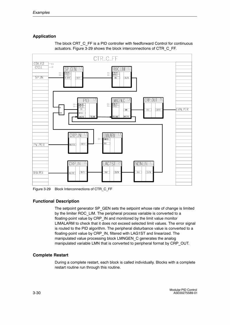
Examples
3-30Modular PID Control
A5E00275589-01
Application
The block CRT_C_FF is a PID controller with feedforward Control for continuousactuators. Figure 3-29 shows the block interconnections of CTR_C_FF.
+
�
Figure 3-29 Block Interconnections of CTR_C_FF
Functional Description
The setpoint generator SP_GEN sets the setpoint whose rate of change is limitedby the limiter ROC_LIM. The peripheral process variable is converted to afloating-point value by CRP_IN and monitored by the limit value monitorLIMALARM to check that it does not exceed selected limit values. The error signalis routed to the PID algorithm. The peripheral disturbance value is converted to afloating-point value by CRP_IN, filtered with LAG1ST and linearized. Themanipulated value processing block LMNGEN_C generates the analogmanipulated variable LMN that is converted to peripheral format by CRP_OUT.
Complete Restart
During a complete restart, each block is called individually. Blocks with a completerestart routine run through this routine.
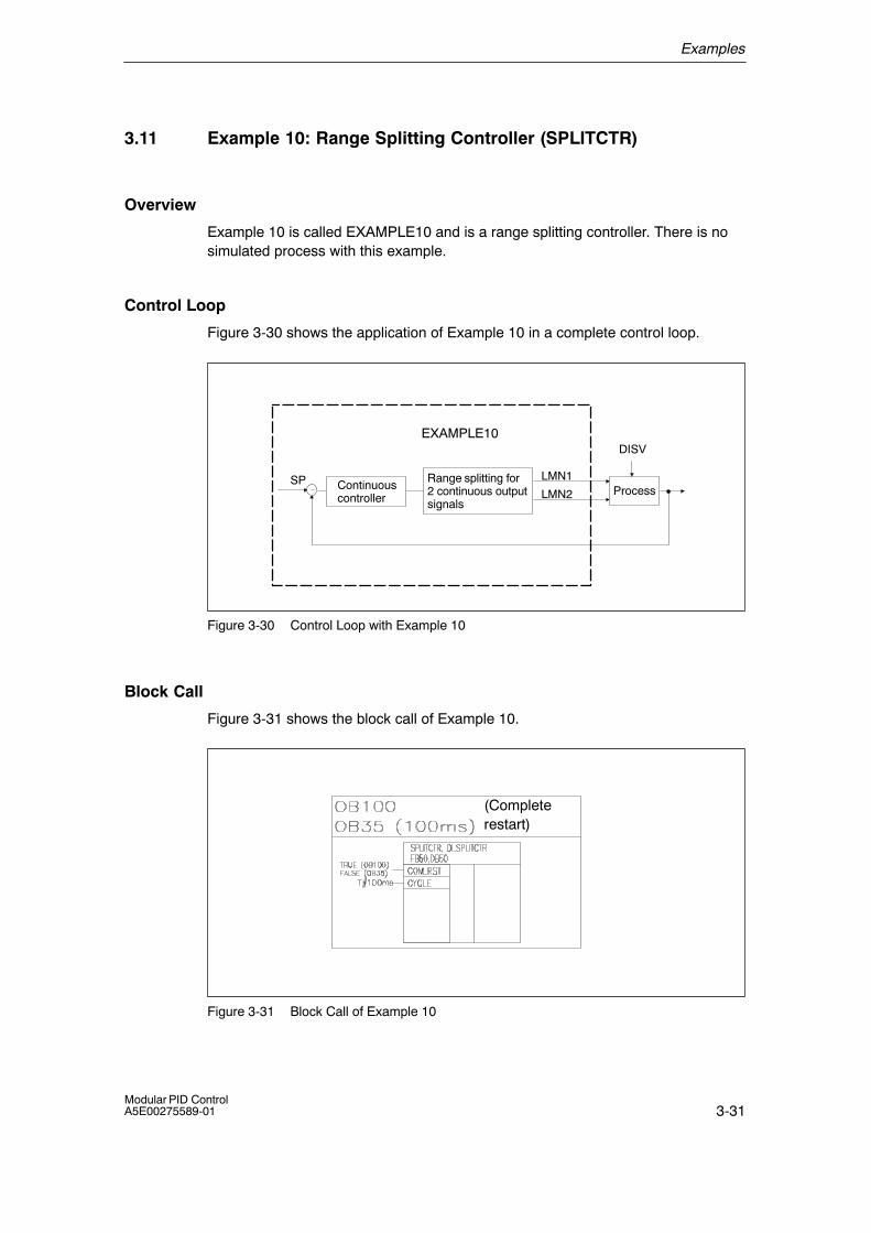
Examples
3-31Modular PID ControlA5E00275589-01
3.11 Example 10: Range Splitting Controller (SPLITCTR)
Overview
Example 10 is called EXAMPLE10 and is a range splitting controller. There is nosimulated process with this example.
Control Loop
Figure 3-30 shows the application of Example 10 in a complete control loop.
EXAMPLE10
Process
DISV
LMN2SP Continuous
controller
LMN1Range splitting for2 continuous outputsignals
Figure 3-30 Control Loop with Example 10
Block Call
Figure 3-31 shows the block call of Example 10.
(Completerestart)
Figure 3-31 Block Call of Example 10
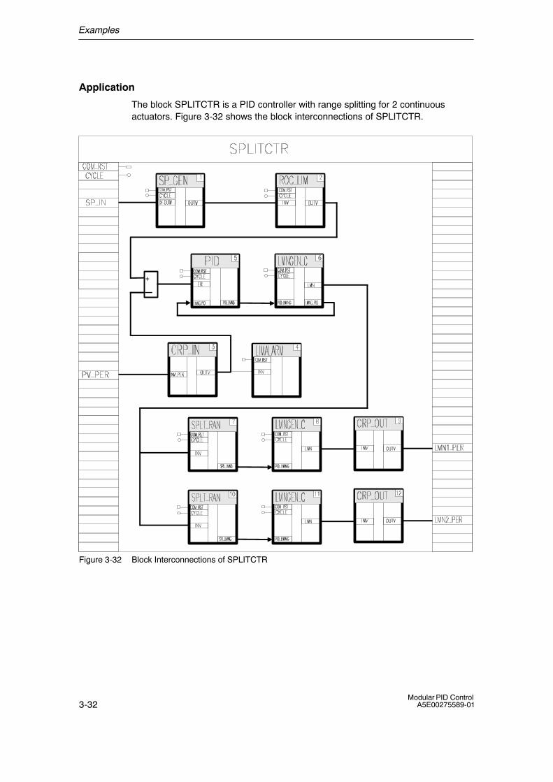
Examples
3-32Modular PID Control
A5E00275589-01
Application
The block SPLITCTR is a PID controller with range splitting for 2 continuousactuators. Figure 3-32 shows the block interconnections of SPLITCTR.
+
�
Figure 3-32 Block Interconnections of SPLITCTR
Examples
3-33Modular PID ControlA5E00275589-01
Functional Description
The setpoint generator SP_GEN sets the setpoint whose rate of change is limitedby the limiter ROC_LIM. The peripheral process variable is converted to afloating-point value by CRP_IN and monitored by the limit value monitorLIMALARM to check that it does not exceed selected limit values. The error signalis routed to the PID algorithm. The manipulated value processing blockLMNGEN_C generates the analog manipulated variable LMN. The manipulatedvalue range is split into two ranges by two SPLT_RAN blocks. For each range,LMNGEN_C calculates an analog manipulated variable that is converted to theperipheral format by CRP_OUT.
Complete Restart
During a complete restart, each block is called individually. Blocks with a completerestart routine run through this routine.
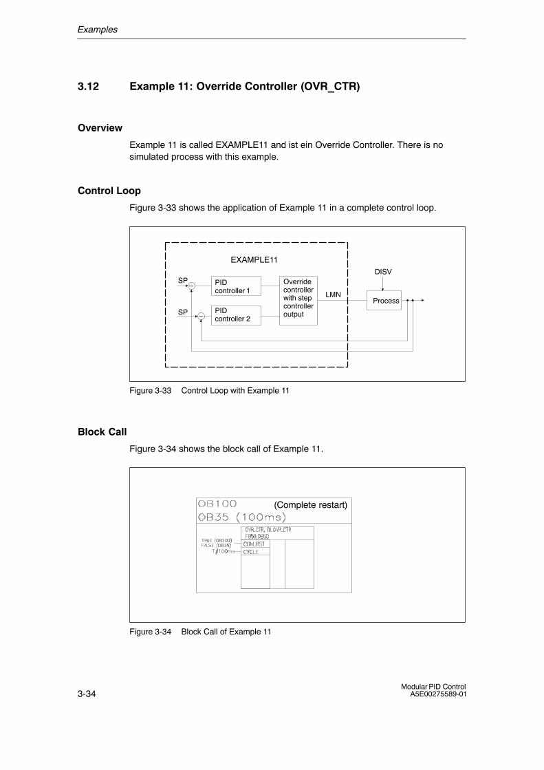
Examples
3-34Modular PID Control
A5E00275589-01
3.12 Example 11: Override Controller (OVR_CTR)
Overview
Example 11 is called EXAMPLE11 and ist ein Override Controller. There is nosimulated process with this example.
Control Loop
Figure 3-33 shows the application of Example 11 in a complete control loop.
�
EXAMPLE11
PIDcontroller 1
Process
DISV
LMN
SP
SP
Overridecontrollerwith stepcontrolleroutputPID
controller 2�
Figure 3-33 Control Loop with Example 11
Block Call
Figure 3-34 shows the block call of Example 11.
(Complete restart)
Figure 3-34 Block Call of Example 11
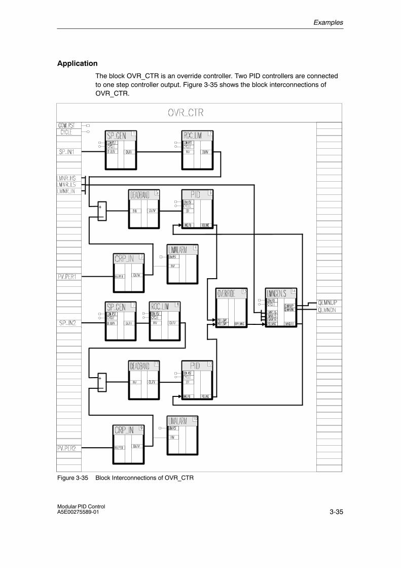
Examples
3-35Modular PID ControlA5E00275589-01
Application
The block OVR_CTR is an override controller. Two PID controllers are connectedto one step controller output. Figure 3-35 shows the block interconnections ofOVR_CTR.
+
�
+
�
Figure 3-35 Block Interconnections of OVR_CTR
Examples
3-36Modular PID Control
A5E00275589-01
Functional Description
The setpoint generators SP_GEN sets the setpoints whose rates of change arelimited by the limiter ROC_LIM. The peripheral process variables are converted tofloating-point values by CRP_IN blocks and monitored by the limit value monitorsLIMALARM to check that they do not exceed selected limit values. The errorsignals are led to the PID algorithm. The manipulated values of the two PID blocksare applied to an OVERRIDE block. Here, either the maximum or the minimum ofthe two manipulated values is determined and passed to the manipulated valueprocessing block LMNGEN_S. In the override controller, LMNGEN_S can onlyoperate in the �step controller with position feedback signal� mode.
Complete Restart
During a complete restart, each block is called individually. Blocks with a completerestart routine run through this routine.
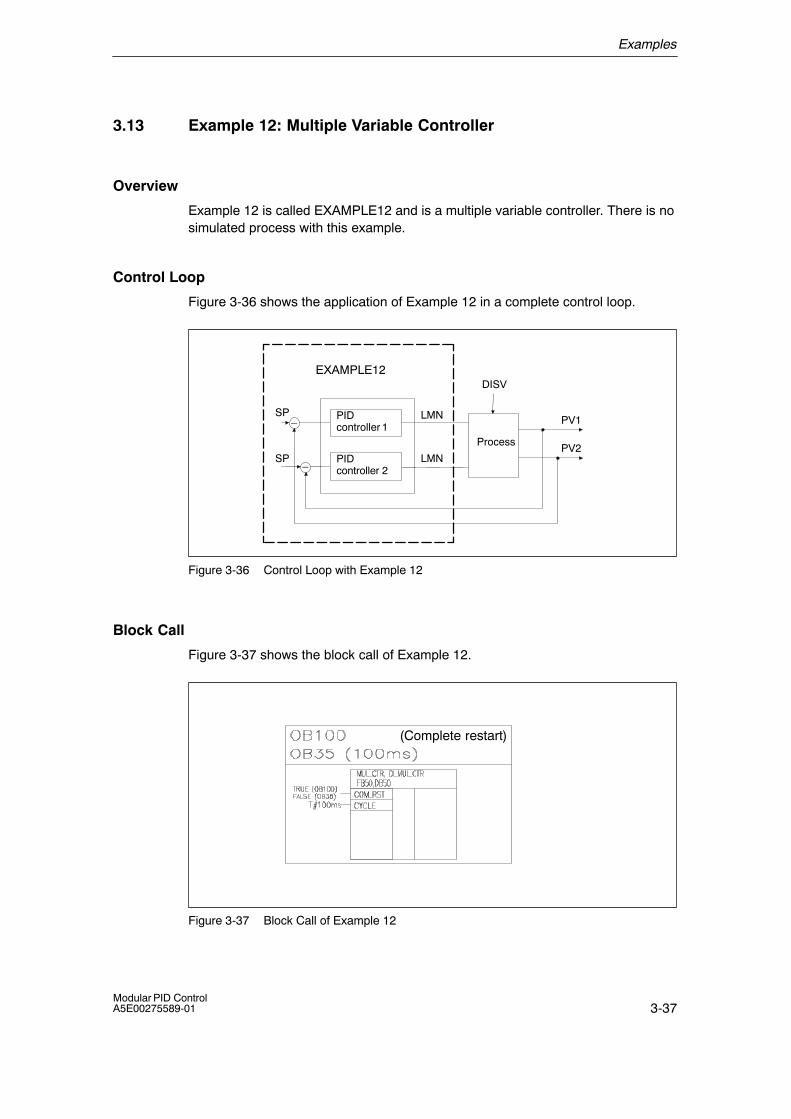
Examples
3-37Modular PID ControlA5E00275589-01
3.13 Example 12: Multiple Variable Controller
Overview
Example 12 is called EXAMPLE12 and is a multiple variable controller. There is nosimulated process with this example.
Control Loop
Figure 3-36 shows the application of Example 12 in a complete control loop.
EXAMPLE12
PIDcontroller 1
Process
DISV
LMNSP
PV1
PV2PIDcontroller 2
LMNSP
�
�
Figure 3-36 Control Loop with Example 12
Block Call
Figure 3-37 shows the block call of Example 12.
(Complete restart)
Figure 3-37 Block Call of Example 12

Examples
3-38Modular PID Control
A5E00275589-01
Application
The block MUL_CTR is a multiple variable controller. Two PID controllers withcontinuous outputs are connected to the process. Figure 3-38 shows the blockinterconnections of MUL_CTR.
+
�
+
�
Figure 3-38 Block Interconnections of MUL_CTR

Examples
3-39Modular PID ControlA5E00275589-01
Functional Description
The functionality of each PID controller is analogous to the continuous controllerPIDCTR_C in Section 3.3.1 on page 3-10.
In this case, the manipulated value of one controller is multiplied by themanipulated value of the other controller.
Complete Restart
During a complete restart, each block is called individually. Blocks with a completerestart routine run through this routine.

Examples
3-40Modular PID Control
A5E00275589-01
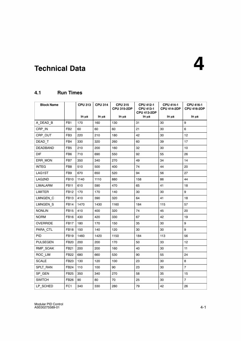
4-1Modular PID ControlA5E00275589-01
Technical Data
4.1 Run Times
Block Name CPU 313
in �s
CPU 314
in �s
CPU 315CPU 315-2DP
in �s
CPU 412-1CPU 413-1
CPU 413-2DPin �s
CPU 414-1CPU 414-2DP
in �s
CPU 416-1CPU 416-2DP
in �s
A_DEAD_B FB1 170 160 130 31 30 9
CRP_IN FB2 60 60 60 21 30 6
CRP_OUT FB3 220 210 180 42 30 12
DEAD_T FB4 330 320 260 60 39 17
DEADBAND FB5 210 200 160 32 30 10
DIF FB6 710 690 550 92 55 26
ERR_MON FB7 350 340 270 49 34 14
INTEG FB8 510 500 400 74 44 20
LAG1ST FB9 670 650 520 94 56 27
LAG2ND FB10 1140 1110 880 158 86 44
LIMALARM FB11 610 590 470 65 41 18
LIMITER FB12 170 170 140 30 30 9
LMNGEN_C FB13 410 390 320 64 41 18
LMNGEN_S FB14 1470 1430 1160 184 115 57
NONLIN FB15 410 400 320 74 45 20
NORM FB16 430 420 330 67 42 19
OVERRIDE FB17 180 170 150 35 30 9
PARA_CTL FB18 150 140 120 30 30 9
PID FB19 1460 1420 1150 184 113 56
PULSEGEN FB20 200 200 170 50 33 12
RMP_SOAK FB21 200 200 160 40 30 11
ROC_LIM FB22 680 660 530 90 55 24
SCALE FB23 130 120 100 23 30 8
SPLT_RAN FB24 110 100 90 23 30 7
SP_GEN FB25 350 340 270 58 35 15
SWITCH FB26 90 80 70 25 30 7
LP_SCHED FC1 340 330 280 79 42 26
4
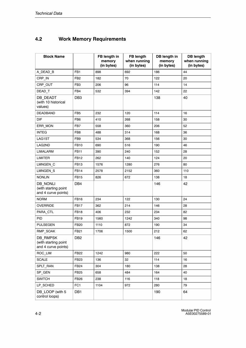
Technical Data
4-2Modular PID Control
A5E00275589-01
4.2 Work Memory Requirements
Block Name FB length inmemory(in bytes)
FB lengthwhen running
(in bytes)
DB length inmemory(in bytes)
DB lengthwhen running
(in bytes)
A_DEAD_B FB1 898 692 186 44
CRP_IN FB2 182 70 122 20
CRP_OUT FB3 206 96 114 14
DEAD_T FB4 532 394 142 22
DB_DEADT(with 10 historicalvalues)
DB3 138 40
DEADBAND FB5 232 120 114 16
DIF FB6 410 268 158 30
ERR_MON FB7 558 360 206 52
INTEG FB8 488 314 168 36
LAG1ST FB9 534 368 156 30
LAG2ND FB10 690 516 190 46
LIMALARM FB11 390 240 152 28
LIMITER FB12 262 140 124 20
LMNGEN_C FB13 1576 1280 276 80
LMNGEN_S FB14 2578 2152 360 110
NONLIN FB15 826 672 138 18
DB_NONLI(with starting pointand 4 curve points)
DB4 146 42
NORM FB16 234 122 130 24
OVERRIDE FB17 362 214 146 28
PARA_CTL FB18 406 232 234 82
PID FB19 1560 1242 340 98
PULSEGEN FB20 1110 872 190 34
RMP_SOAK FB21 1706 1500 212 62
DB_RMPSK(with starting pointand 4 curve points)
DB2 146 42
ROC_LIM FB22 1242 980 222 50
SCALE FB23 136 32 114 16
SPLT_RAN FB24 304 180 138 28
SP_GEN FB25 658 484 164 40
SWITCH FB26 238 116 118 18
LP_SCHED FC1 1104 972 280 79
DB_LOOP (with 5control loops)
DB1 190 64
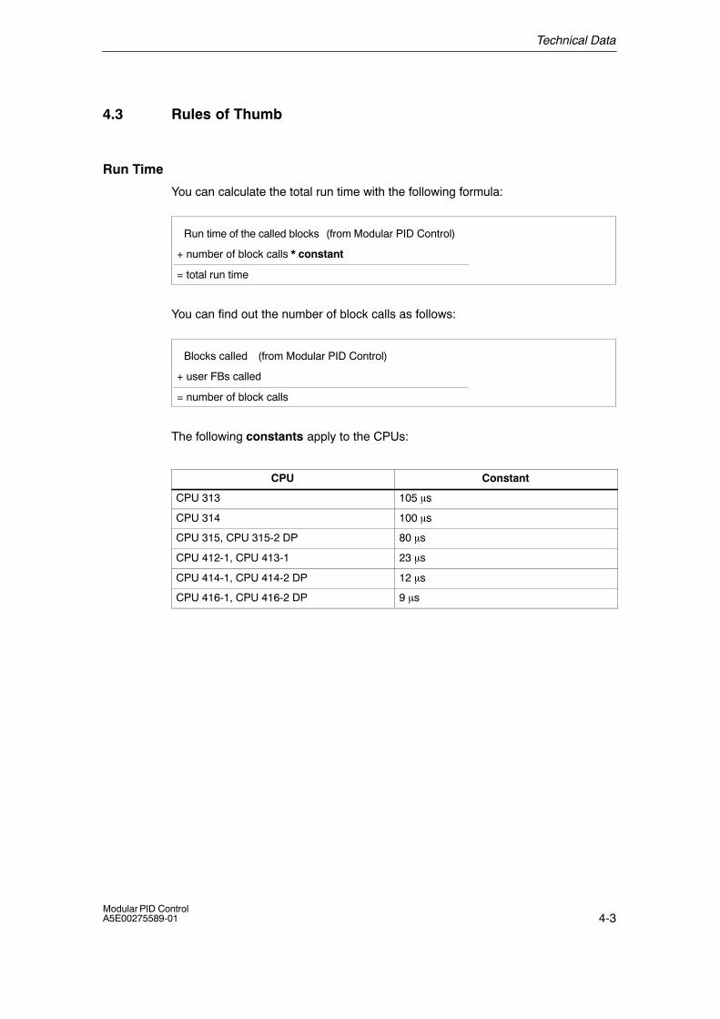
Technical Data
4-3Modular PID ControlA5E00275589-01
4.3 Rules of Thumb
Run Time
You can calculate the total run time with the following formula:
= total run time
Run time of the called blocks (from Modular PID Control)
+ number of block calls * constant
You can find out the number of block calls as follows:
= number of block calls
Blocks called
+ user FBs called
(from Modular PID Control)
The following constants apply to the CPUs:
CPU Constant
CPU 313 105 �s
CPU 314 100 �s
CPU 315, CPU 315-2 DP 80 �s
CPU 412-1, CPU 413-1 23 �s
CPU 414-1, CPU 414-2 DP 12 �s
CPU 416-1, CPU 416-2 DP 9 �s
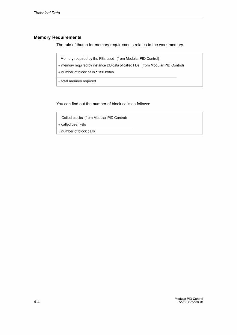
Technical Data
4-4Modular PID Control
A5E00275589-01
Memory Requirements
The rule of thumb for memory requirements relates to the work memory.
= total memory required
Memory required by the FBs used (from Modular PID Control)
+ memory required by instance DB data of called FBs (from Modular PID Control)
+ number of block calls * 120 bytes
You can find out the number of block calls as follows:
= number of block calls
Called blocks
+ called user FBs
(from Modular PID Control)
5-1Modular PID ControlA5E00275589-01
Configuration Tool for Modular PID Control
Requirements
STEP 7 must be installed correctly on your programming device/PC.
Diskettes
The software is supplied on CD.
Installation
To install the software, follow the steps below:
1. Insert the CD in the CD drive of your programming device/PC.
2. Start the dialog for installing software under WINDOWS by double-clicking the�Add/Remove Programs� icon in the �Control Panel�.
3. Select the CD drive and the file Setup.exe and start installation.The configuration tool is then installed on your system.
4. Follow the instructions displayed by the installation tool step by step.
Readme File
Important up�to�date information about the supplied software is stored on thereadme file. You will find this file in the Windows Start menu via START > SIMATIC> Product Information > English.
Purpose
The configuration tool is intended to make installation, startup and testing of yourcontroller easier leaving you free to concentrate on the real control problem inhand.
Functions of the configuration tool
Each function has its own window. You can also call a function more than once, inother words, you can, for example, display the loop monitors of more than onecontroller at the same time.
5
Configuration Tool for Modular PID Control
5-2Modular PID Control
A5E00275589-01
Monitoring Controllers
Using the curve recorder function, you record the values of selected variables inthe control loop over time and display them. Up to four variables can be displayedat the same time.
With the loop monitor function, you can display the relevant control variables(setpoint, manipulated variable, and process variable) of a selected controller.
Process Identification
Using the process identification function, you can find out the optimum controllersetting for a particular control loop. The characteristics of the process are identifiedexperimentally. Based on these characteristics, the ideal controller parameters arecalculated and saved for future use.
Manual Control
The loop monitor function allows you to modify or set new values for relevantvariables of the control loop.
Integrated Help
The configuration tool has an integrated help system that supports you whileworking with the tool. You can call the help system as follows:
• With the menu command Help � Contents
• By pressing the F1 key
• By clicking the Help button in the individual dialogs.
A-1Modular PID ControlA5E00275589-01
References
Further Reading
The following books deal with the basics of control engineering:
/350/ User manual: SIMATIC 7, Standard Control
/352/ J. Gißler, M. Schmid: Vom Prozeß zur Regelung. Analyse, Entwurf, Realisierung inder Praxis. Siemens AG. ISBN 3-8009-1551-0.
A

References
A-2Modular PID Control
A5E00275589-01
References
Index-1Modular PID ControlA5E00275589-01
Index
AAdaptation of the dead band, 2-4
BBlending controller, 3-22Block Diagram, NORM, 2-75Block diagram
A_DEAD_B, 2-2CRP_IN, 2-8CRP_OUT, 2-10DEAD_T, 2-12DEADBAND, 2-16DIF, 2-19ERR_MON, 2-23INTEG, 2-27LAG1ST, 2-33LAG2ND, 2-37LIMALARM, 2-41LIMITER, 2-45LMNGEN_C, 2-48LMNGEN_S, 2-54LP_SCHED, 2-63NONLIN, 2-70OVERRIDE, 2-77PARA_CTL, 2-80PID, 2-84PULSEGEN, 2-94RMP_SOAK, 2-104ROC_LIM, 2-114SCALE, 2-123SP_GEN, 2-125SPLT_RAN, 2-129SWITCH, 2-133
CCall data, 2-1
Call processing, 2-68Cascade controller, 3-25Change range peripheral input, 2-8Change range peripheral output, 2-10Controller structures, examples, 3-1Controller with feedforward control, 3-29Controller with precontroller, 3-27
DDead band, 2-16Dead band, adaptive, 2-2Dead time, 2-12Differentiator, 2-19Disabling loops, 2-68
EError signal monitoring, 2-23
FFirst-order lag element, 2-33Fixed setpoint controller, 3-6Fixed setpoint controller with continuous
output, 3-10Fixed setpoint controller with switching output
for integrating actuators, 3-4for proportional actuators, 3-12
HHardware environment, 1-3
IInput Parameters, DEAD_T, 2-13
Index
Index-2Modular PID Control
A5E00275589-01
Input parametersA_DEAD_B, 2-6CRP_IN, 2-9CRP_OUT, 2-11DEADBAND, 2-17DIF, 2-19ERR_MON, 2-25INTEG, 2-28LAG1ST, 2-33LAG2ND, 2-39LIMALARM, 2-42LIMITER, 2-46LMNGEN_C, 2-49LMNGEN_S, 2-56LP_SCHED_S, 2-64NONLIN, 2-72NORM, 2-76OVERRIDE, 2-78PARA_CTL, 2-81PID, 2-85PULSEGEN, 2-96RMP_SOAK, 2-106ROC_LIM, 2-116SCALE, 2-124SP_GEN, 2-126SPLT_RAN, 2-131SWITCH, 2-134
Integrator, 2-27
LLimit alarm, 2-41Limiter, 2-45Linear scaling, 2-123Loop call (LP_SCHED), 2-67Loop calls
conditions, 2-69example, 2-69
Loop scheduler, 1-1, 2-63parameter assignment, 2-67
MManipulated value, changing to the Startup and
Configuration tool, 2-53Memory requirements, 4-5Minimum break time, 2-99Minimum pulse time, 2-99
Modular PID Control, 1-1concept, 1-1range of functions, 1-4software environment, 1-3software product, 1-2
Multiple variable controller, 3-37
NNon-linear static function, 2-70
OOutput continuous PID controller, 2-48Output parameters
A_DEAD_B, 2-6CRP_IN, 2-9CRP_OUT, 2-11DEAD_T, 2-14DEADBAND, 2-17DIF, 2-20ERR_MON, 2-26INTEG, 2-28LAG1ST, 2-34LAG2ND, 2-40LIMALARM, 2-43LIMITER, 2-47LMNGEN_C, 2-50LMNGEN_S, 2-57LP_SCHED_S, 2-64NONLIN, 2-72NORM, 2-76OVERRIDE, 2-78PARA_CTL, 2-81PID, 2-87PULSEGEN, 2-96RMP_SOAK, 2-106ROC_LIM, 2-117SCALE, 2-124SP_GEN, 2-127SPLT_RAN, 2-131SWITCH, 2-134
Output PID step controller, 2-54Override control, 2-77Override controller, 3-34

Index
Index-3Modular PID ControlA5E00275589-01
PParameter control, 2-80Physical normalization, 2-75PID algorithm, 2-84Pulse generator, 2-94
accuracy, 2-97automatic synchronization, 2-97modes, 2-98
Pulse output, switching, 2-99
RRamp, 2-114Ramp soak, 2-104
activating, 2-109cyclic mode, 2-111default output value, 2-110hold, 2-111holding, continuing, 2-112modes, 2-108, 2-109online changes, 2-113starting, 2-110
Range splitting controller, 3-31Rate of change limiter, 2-114Ratio controller
multiple-loop, 3-18single-loop, 3-16
Readme file, 5-1Rules of thumb, 4-4Run times, 4-1
rules of thumb, 4-4
SSetpoint generator, 2-125Software environment, 1-3Split Ranging, 2-129Standard controller
basic functions, 1-1functions, 1-1
Startup and Test toolintegrated help, 5-2software requirements, 5-1
Step controller, 3-8Subfunctions, 1-1Switch, 2-133
TTechnical data, 4-1Three-step control, 2-99Three-step controller
asymmetrical characteristics, 2-100characteristics, 2-100manual mode, 2-103
Time lag, 2nd order, 2-37Two-step controller, 2-101
WWork memory requirements, 4-2

Index
Index-4Modular PID Control
A5E00275589-01


