Embed Size (px)
Citation preview

WWW.PdMsolutions.com
Piedmont Chapter Vibration Institute
Training Symposium 10 May, 2012
FIELD BALANCING OF ROTATING
MACHINERY

Presenter: William T. Pryor III
Senior Technical Director
PdM Solutions, Inc.
Vibration Analyst Category IV
Member VI Board of Directors
609-330-3995

Presentation is going to concentrate on setting up and performing a single plane balance using Vector and Influence Coefficient methods:
1. Setting up for success
2. Trial Weight Selection
3. Trial Weight Placement
4. Single Plane Calculation

Is Balance the Problem
Technique and Strategy
Unusual Problems Mass Unbalance
Force Rotor Classification
Balancing Techniques Pre-balancing
Checks Trial Weight Selection
& Location
Balancing Pitfalls
Single Plane Balancing
Two Plane Balancing
Balance Limits
Conclusions

Modern Techniques and Instrumentation
Field Balancing an Indirect Process
Analyst’s Goals
Beware of Black Boxes and Traps

Mass unbalance (heavy spot) cannot be measured directly
High spot (angular location of peak or peak to peak vibration) is used to determine heavy spot
Balancing is an art and science ◦ science in the vector procedures ◦ art in selection of balance planes, speeds, measurement
locations as well as trial weight sizes and locations
Balancing is a method of weight compensation to minimize vibration
Global weights added to compensate for local unbalances – can introduce stress

Is Balance the Problem?
Beware of false indicators - Misalignment & Resonance
Unbalance a Rotating Force
Resonance and Flexible Structures Complicate the Picture

Vibration Transducer
Once-Per-Revolution Sensor
Filter capable of measuring Speed, Amplitude, and Phase
Marker or Paint Stick
Polar Graph Paper and Triangles
Balance Weights and Scale

Rule #1 – Keep it Simple
Rule #2 – Be Consistent
Rule #3 – Do not make up your own rules
Rule #4 – Remember the 1st 3 rules

Before attempting to balance:
Remember there are multiple reasons for a high 1X amplitude component.
Perform a complete analysis prior to balancing to ensure that other mechanical faults are not the cause of the 1X response.

Misalignment
Thermal Effects
Product buildup on rotor
Erosion or corrosion of rotor
Bowed, bent, or eccentric shaft
Bearing or seal wear
Roller Deflection – Paper Machines
Machining errors/incorrect assembly
Not properly balanced in shop
Looseness in built-up rotor components

Not mass unbalance
Loose supports
Frame misalignment
Stiffness asymmetry
Inaccurate data
Thermal sensitivity
Resonance
Unbalance distribution

1. The rotating component did not go out of balance by itself.
2. Remain skeptical during the balancing process and use the balancing procedure as a diagnostic tool.
3. If balance attempt is not working as anticipated – STOP and THINK about what is going on. It may not be unbalance.

1) Number Fan Blades or Holes 0 to N.
As an example: if there are 8 Blades, Blade 0 is also Blade 8 (0
to 360 Degrees). Blade #’s will increase in sequence by turning
the rotor in the direction of rotation.
2) Install Vibration measurement sensor Inline with Blade 0
3) Install Once-per Rev timing mark and sensor when Blade 0 is
inline with measurement sensor.
4) Make a drawing showing blades, transducer placement, and
angles. Remember angles increase against rotation.
5) Determine trial weight amount and have weight available.


When we balance a rotor there are 2 unknown factors which need to be determined in order to solve a rotor balance problem.
1) The amount of weight required 2) Angle of weight placement

Speed of the machine
Radius of weight placement
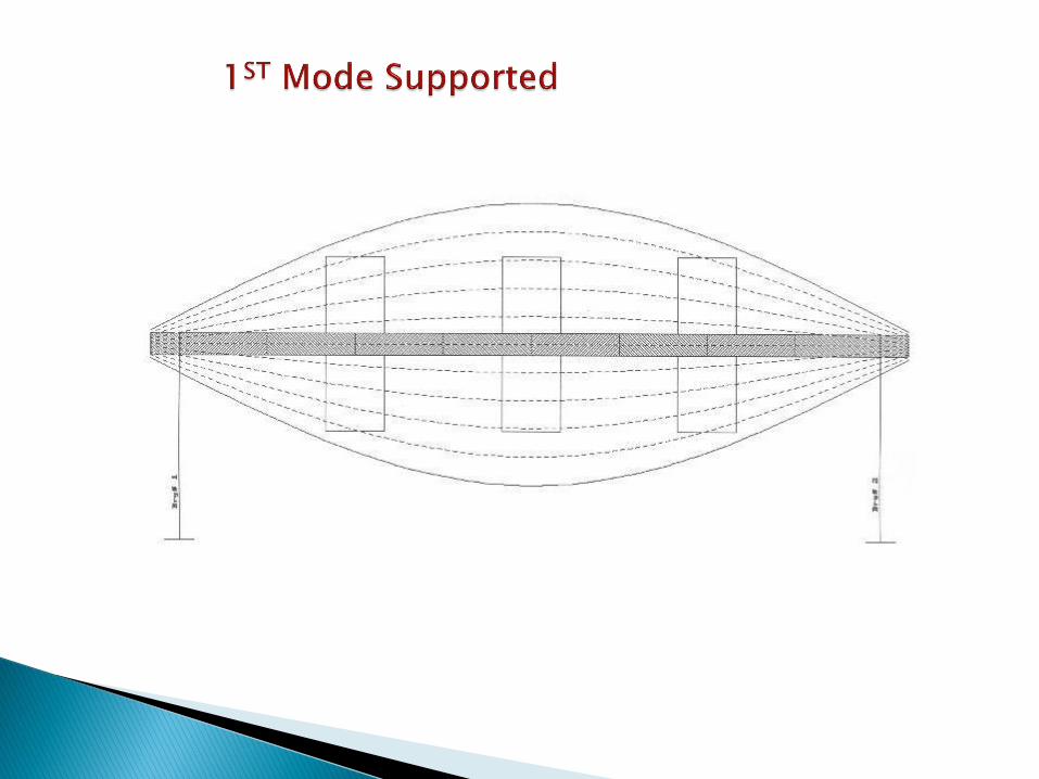
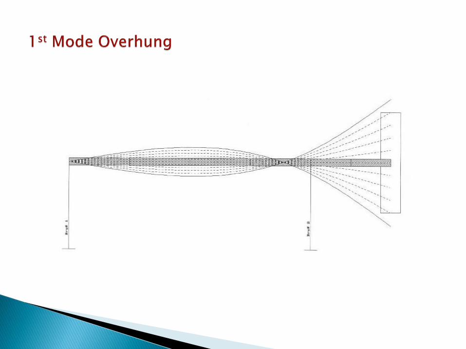
Rotor mode shape relative to balance plane selected
Proximity to Rotor Balance Resonance (Critical Speed)

Balance trial weight selection should be based on 1 of the following:
A: User experience with the same or like machine.
B: Experience with similarly designed and constructed machine.
C: In the absence of above, a trial weight is calculated to generate a centrifugal force equal to 10% of the rotors weight. Note: For rotors operating above 3600 some suggest that a calculation yielding 5% of the rotors weight should be used as an initial trial weight.
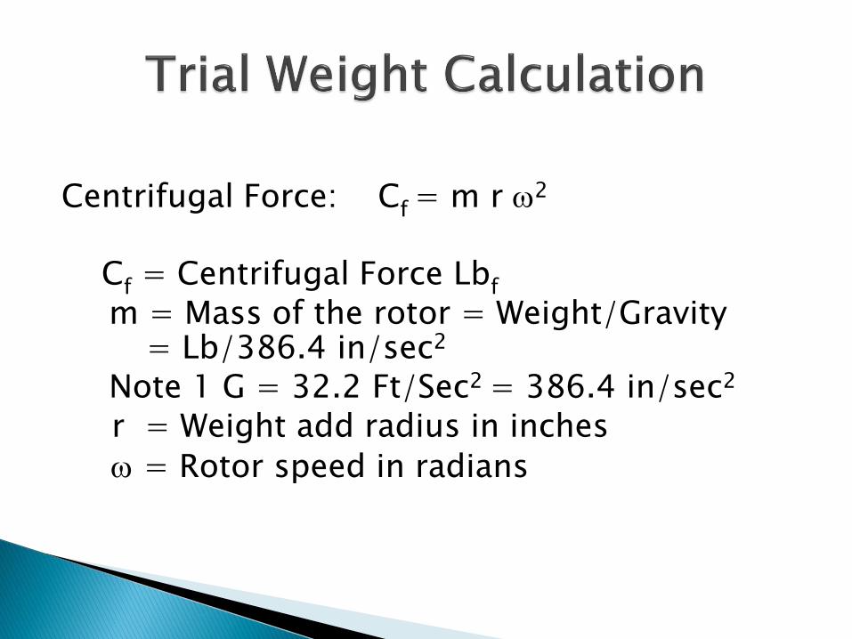
Centrifugal Force: Cf = m r 2 Cf = Centrifugal Force Lbf
m = Mass of the rotor = Weight/Gravity = Lb/386.4 in/sec2
Note 1 G = 32.2 Ft/Sec2 = 386.4 in/sec2 r = Weight add radius in inches
= Rotor speed in radians

Calculate the size of the trial weight needed for an electric AC motor operating at 1785 RPM. The rotor weighs 1800 pounds and the weight can be added to the rotor at a radius of 6 inches.
The easiest way to treat this problem is to break it down into a couple of parts.
1st we want our trial weight to generate a force equal to 10% of the rotor weight. So from our example:
Cf = 1800 Lb Rotor/10 = 180#

2nd Our weight add radius is 6”
3rd We need to calculate the speed of the rotor in radians.
1785 RPM * 2
= 60 sec/Min = [2(29.75 Hz)] =
[2* 3.14*29.75 Hz] = 186.83 Radians/Sec
Note: 1 Radian = 2 = 360 Degrees
2 = (186.83)2 = (186.83 * 186.83) = 34905.45 Radians/Sec2

Centrifugal Force: Cf = m r 2
__Cf __
m = r 2
________180#_______ __#___
m = (6”)(34905.45 radians) = 0.000859 in/sec2
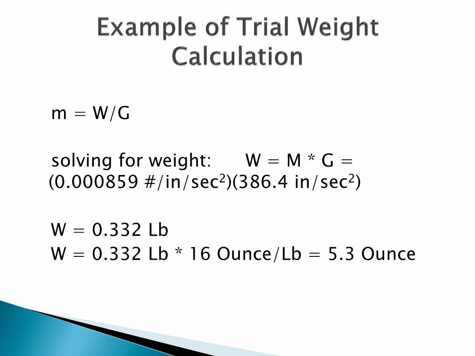
m = W/G
solving for weight: W = M * G = (0.000859 #/in/sec2)(386.4 in/sec2)
W = 0.332 Lb
W = 0.332 Lb * 16 Ounce/Lb = 5.3 Ounce

T 2
WW 56375.5
N r
where: WT = trial weight, oz. r = eccentricity of trial weight, in. W = static weight of rotor, lb. N = speed of rotor, RPM

where: WT = trial weight, oz. r = eccentricity of trial weight, in. = 6” W = static weight of rotor, lb. = 1800# N = speed of rotor, RPM = 1785 RPM
Wt = 56375.5 (1800 #) = 5.3 Oz. (1785 RPM)2 * 6”

Proximity to Rotor Balance Resonance (Critical Speed)
(relationship of rotor high spot to heavy spot)
Rotor mode shape

Initially the angular relationship of the Heavy Spot to the High Spot is unknown.
Vibration Institute Balance of Rotating Machines

Vibration Institute Balance of Rotating Machines

Below resonance add 1800
At resonance add 900
Above resonance add 00
If unknown it is usually safe to add 900
Remember the purpose of a trial weight is to cause the rotor to display a reasonable amplitude and/or phase change compared to the initial unbalance run. An amplitude and/or phase change is required in order to perform the balancing calculation. An amplitude change of 10% or phase change of at least 150 is desired.


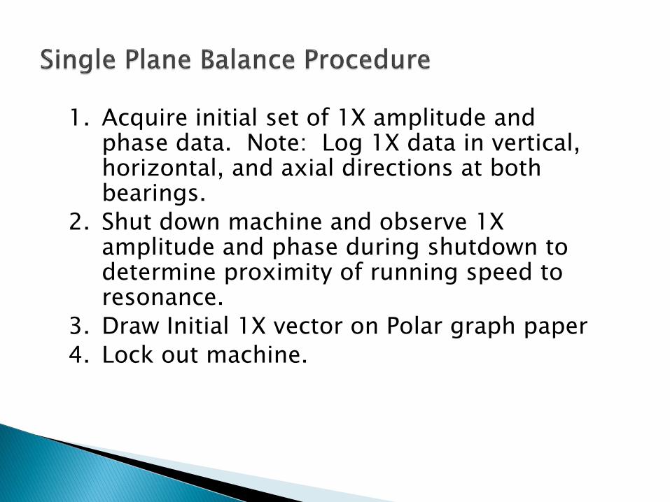
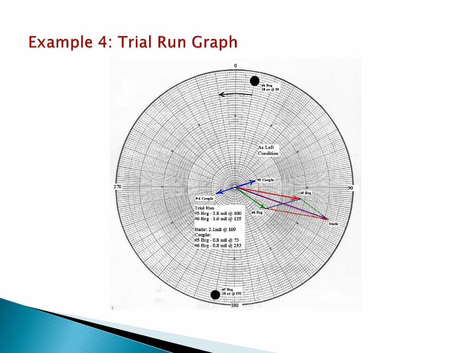
1. Acquire initial set of 1X amplitude and phase data. Note: Log 1X data in vertical, horizontal, and axial directions at both bearings.
2. Shut down machine and observe 1X amplitude and phase during shutdown to determine proximity of running speed to resonance.
3. Draw Initial 1X vector on Polar graph paper
4. Lock out machine.

5. Determine trial weight angular placement. Show trial weight magnitude and placement on polar graph.
6. Attach trial weight to rotor.
7. Release locks
8. Run machine and log 1X amplitude and phase at all locations. (Trial Run).
9. Shutdown machine and lock out equipment.
10.REMOVE TRIAL WEIGHT

11. Draw Trial Weight vector on polar graph.
12. Perform balance calculations to determine magnitude and angle of corrective weight.
13. Attach weight to machine.
14. Release locks and run equipment.
15. Log 1X amplitude and phase at all locations and evaluate data. • Did 1X amplitudes decrease at all locations. If
not, this may not be just a balance issue. • Is a trim run required to reduce levels to
desired magnitude.

16. For trim run use Sensitivity/Response Vector to calculate trim balance correction, lock out machine and repeat steps 13-15
Note: If amplitudes do not decrease following trim balance it is probably not a mass unbalance problem. Review data!

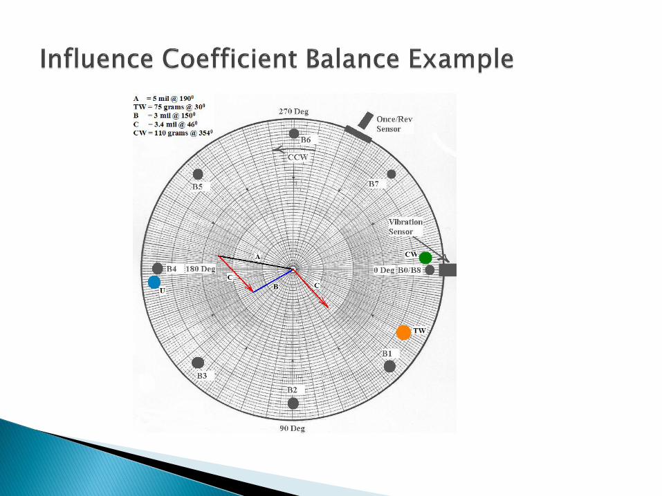
1. A = Initial Vibration Response ( Mil @ Angle)
2. TW = Trial Weight Placement (Weight @ Angle)
3. B = Trial Weight Vector = A + Effect of Trial Weight (Mil @ Angle)
4. C = Trial Weight Effect = B - A (Draw a line from the head of the A to the head of the B vector. Measure the magnitude of C
5. Calculate the Rotor Sensitivity to weight = S = TW/C (Weight/Mil)

6. Calculate the Correction Weight = (Sensitivity) (Initial Response)
7. Measure the angle between C and A. (This is the number of degrees that weight must be rotated from Trial Weight location)
8. Draw arrow from C to A. (This is the direction to move final balance weight from trial weight location)
9. Show the final balance weight location on the polar graph.
10. Show location of rotor heavy spot on the graph.
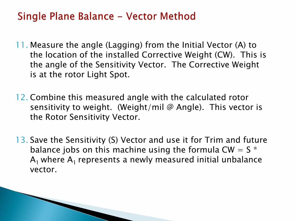
11. Measure the angle (Lagging) from the Initial Vector (A) to the location of the installed Corrective Weight (CW). This is the angle of the Sensitivity Vector. The Corrective Weight is at the rotor Light Spot.
12. Combine this measured angle with the calculated rotor sensitivity to weight. (Weight/mil @ Angle). This vector is the Rotor Sensitivity Vector.
13. Save the Sensitivity (S) Vector and use it for Trim and future balance jobs on this machine using the formula CW = S * A1 where A1 represents a newly measured initial unbalance vector.


Correction Weight = CW
CW = 110 grams @ 3540
Heavy Spot = U
U = 110 grams @ 1740

Rotor Sensitivity = S
S = 22 Grams/mil @ 1640
Proof:
CW = S * A1
CW = (22 gram/mil @ 1640)(5 mil @ 1900)
CW = 110 gram @ 3540

1. A = Initial Vibration Response ( Mil @ Angle)
2. TW = Trial Weight Placement (Weight @ Angle)
3. B = Trial Weight Vector = A + Effect of Trial Weight (Mil @ Angle)
4. C = Trial Weight Effect = B - A (Draw a line from the head of the A to the head of the B vector. Measure the magnitude of C
5. Calculate the Unbalance Influence Coefficient
R11 = ___C (mil @ Angle)__ Response at plane 1 to weight at plane 1
TW (weight @ Angle)

6. Calculate the location of the Heavy Spot
U11 = ____A_(mil @ Angle)___ Unbalance at Plane 1
R11 (mil/weight @ Angle) 7. Weight Add Solution = U11 + 1800 (Light Spot)
8. Show location of Heavy Spot and Light Spot on graph 9. Save Influence Coefficient for future balance work on this
equipment


The Influence Coefficient provides powerful insight into a rotor behavior.
1. The influence Coefficient for a given rotor should not change over the life of the equipment. Changes in magnitude or angle indicate changes in rotor/support condition or may be the result of external forces such as misalignment.
2. The angle of the Influence Coefficient documents the relationship of the Rotor Heavy Spot (Force) to the Rotor High Spot. Hence, the angle documents where a rotor is running relative to its Critical Speed.

1) A = Initial Vibration Response (2.3 Mil @ 420)
2) TW = Trial Weight Placement (60 Gm @ 740)
3) B = A + Effect of Trial Weight (4.3 Mil @ 570)
4) C = B – A = Effect of Trial Weight (2.2 Mil @ 730)
5) R11 = 2.2 Mil @ 730 = 0.036 mil/Gm @ 3590
60 Gm @ 740
6) U11 = ____2.3 Mil @ 420___ = 63.9 Gm @ 430
0.036 mil/Gm @ 3590
7) Weight Add Solution = U11 + 1800 = 63.9 Gm @ 2230


1) A = Initial Vibration Response (5.7 Mil @ 1680)
2) TW = Trial Weight Placement (5 Gm @ 2700)
3) B = A + Effect of Trial Weight (3.3 Mil @ 1550)
4) C = B – A = Effect of Trial Weight (2.59 Mil @ 40)
5) R11 = 2.59 Mil @ 40 = 0.519 mil/Gm @ 940
5 Gm @ 2700
6) U11 = ____5.7 Mil @ 1680___ = 10.98 Gm @ 740
0.519 mil/Gm @ 940
7) Weight Add Solution = U11 + 1800 = 13.26 Gm @ 2540


1) A = Initial Vibration Response (4.9 Mil @ 2640)
2) TW = Trial Weight Placement (5 Gm @ 2700)
3) B = A + Effect of Trial Weight (3.0 Mil @ 2590)
4) C = B – A = Effect of Trial Weight (1.93 Mil @ 920)
5) R11 = 1.93 Mil @ 920 = 0.386 mil/Gm @ 1820
5 Gm @ 2700
6) U11 = ____4.9 Mil @ 2640___ = 12.7 Gm @ 820
0.386 mil/Gm @ 1820
7) Weight Add Solution = U11 + 1800 = 12.7 Gm @ 2620


1) A = Initial Vibration Response (2.9 Mil @ 660)
2) TW = Trial Weight Placement (18 Oz @ 1900)
3) B = A + Effect of Trial Weight (0.8 Mil @ 730)
4) C = B – A = Effect of Trial Weight (2.2 Mil @ 2440)
5) R11 = 2.2 Mil @ 2440 = 0.122 mil/Oz @ 540
18 Oz @ 1900
6) U11 = ____2.9 Mil @ 660___ = 23.8 Oz @ 120
0.122 mil/Gm @ 540
7) Weight Add Solution = U11 + 1800 = Brg #5 23.8 Oz @ 1920
Brg #6 23.8 Oz @ 120
Based On #5 Bearing

Initial Unbalance A1 = S11 U1 + S12 U2 A2 = S21 U1 + S22 U2 A1 = Vibration Response at bearing #1 A2 = Vibration Response at bearing #2 U1 = Unbalance at Plane #1 U2 = Unbalance at Plane #2 S11 = Sensitivity of unbalance at Plane #1 to Location #1 S21 = Sensitivity of unbalance at Plane #1 to Location #2 S12 = Sensitivity of unbalance at Plane #2 to Location #1 S22 = Sensitivity of unbalance at Plane #2 to Location #2

W1 = Trial weight at Plane #1
B11 = Vibration at Brg #1 with TW at Plane #1
B21 = Vibration at Brg #2 with TW at Plane #1
W2 = Trail weight at Plane #2
B12 = Vibration at Brg #1 with TW at Plane #2
B22 = Vibration at Brg #2 with TW at Plane #2

Effect of Trial Weights W1 and W2 at each measurement plane
C11 = B11 – A1 Response at Brg #1 to W1 C21 = B21 – A2 Response at Brg #2 to W1 C12 = B12 – A1 Response at Brg #1 to W2 C22 = B22 – A2 Response at Brg #2 to W2 Calculate the Sensitivity (Influence Coefficient) S11 = C11 / W1 S21 = C21 / W1 S12 = C12 / W2 S22 = C22 / W2

Amount of unbalance at each plane
U1 = (S22 A1 – S12 A2) / (S22 S11 – S12 S21)
U2 = (S11 A2 – S21 A1) / (S22 S11 – S12 S21)
Note: For weight add solution 1800 needs to be added to calculated unbalance vectors.

Balance Data


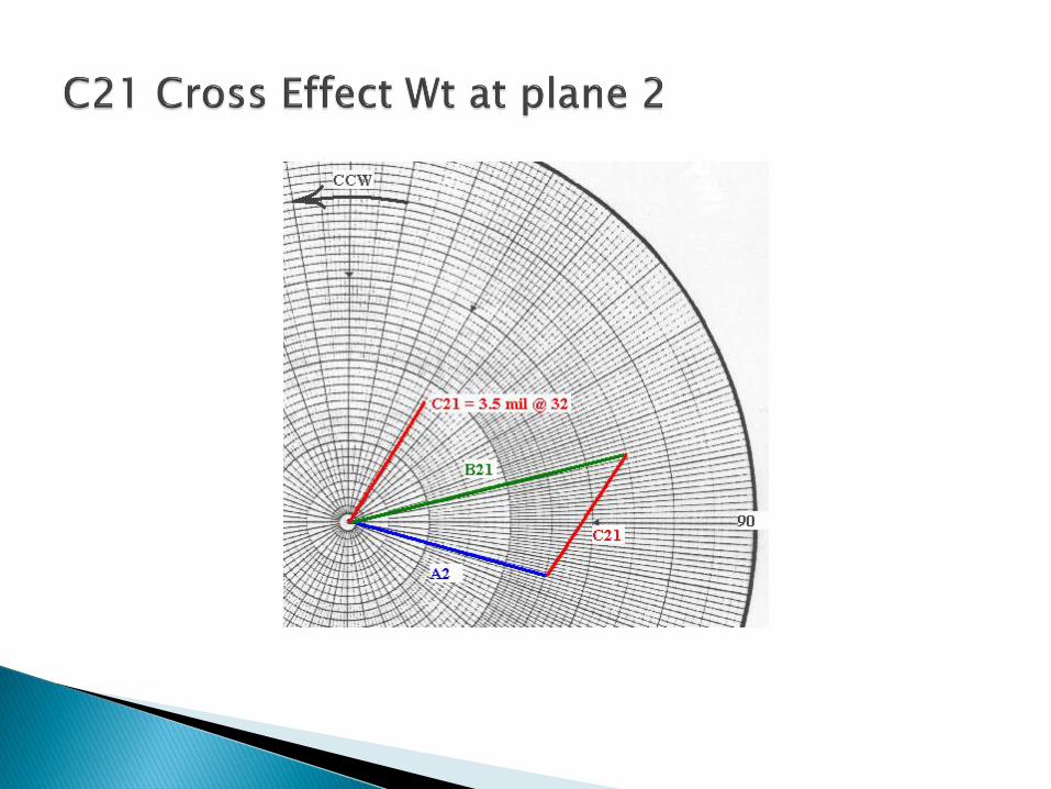
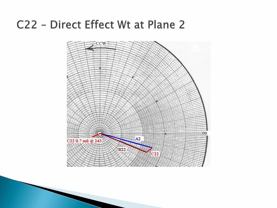

Calculated Solution: Plane 1 = 82 gr. @ 80 Plane 2 = 106 gr. @ 159

Shop
◦API
◦ ISO G1.0
◦Force
Field

API /NAVY
4Woz in
N

NAVY/API
Ur = (oz.-in.) residual unbalance
W = weight of rotor at journal, lb.
N = speed of rotor, RPM
Ur = residual unbalance, oz.-in.
4W
N

EXAMPLE: 1,000 lb. journal WT @ 6,000 RPM
Ur = = 0.667 oz.-in.
e Pk = eccentricity =
vibration Pk-Pk = 2 x e = 2 x .00004167 = 83.33 in. = 0.083 mils Pk to Pk
4 1,000
6,000
.667 oz. in.41.67 micro inches
oz.1,000 lb. x 16
in.

ISO 1.0 mm/sec. = G1.0 (on the rotor not pedestal)
Ve Displacement
2 f
Balancing machine limit ~ 20 micro inches

2
1F Rotor WT
10
2 NF Me
60

F = me2
F =
Wb =
Ur =
G = 386.1 in./sec.2 W = rotor WT, lb. N = RPM of rotor
2W 2 N
eg 60
2
rW 60
U g lb. in.10 2 N
260
1.6 g W oz. in.2 N

EXAMPLE: 2,000 lb rotor @ 6,000 RPM
WT per journal 1,000 lb.
2
r
r r
60U 1.6 x 386.1 x 1,000
2 6,000
453.4U 1.57 oz. in. or U x 44.4 gm in.
16
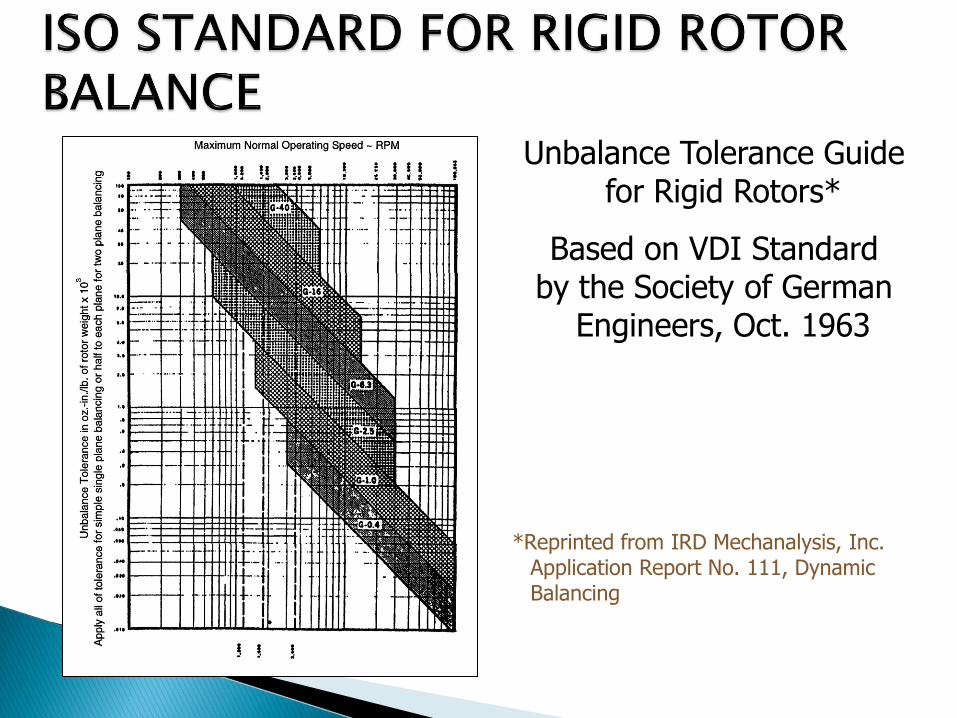
Unbalance Tolerance Guide for Rigid Rotors*
Based on VDI Standard by the Society of German
Engineers, Oct. 1963
*Reprinted from IRD Mechanalysis, Inc. Application Report No. 111, Dynamic Balancing
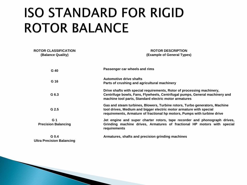
ROTOR CLASSIFICATION
(Balance Quality)
ROTOR DESCRIPTION
(Example of General Types)
G 40 Passenger car wheels and rims
G 16 Automotive drive shafts
Parts of crushing and agricultural machinery
G 6.3
Drive shafts with special requirements, Rotor of processing machinery,
Centrifuge bowls, Fans, Flywheels, Centrifugal pumps, General machinery and
machine tool parts, Standard electric motor armatures
G 2.5
Gas and steam turbines, Blowers, Turbine rotors, Turbo generators, Machine
tool drives, Medium and bigger electric motor armature with special
requirements, Armature of fractional hp motors, Pumps with turbine drive
G 1
Precision Balancing
G 0.4
Ultra Precision Balancing
Jet engine and super charter rotors, tape recorder and phonograph drives,
Grinding machine drives, Armatures of fractional HP motors with special
requirements
Armatures, shafts and precision grinding machines

pert
T 6.015 GWallowable vibration V x
W x R N
where Vper = mils pk to pk
T = effect vector, mils pk to pk
Wt x R = trial wt (oz.) x radius (in.)
G = ISO grade
W = weight of rotor (lb.)
N = Speed, RPM
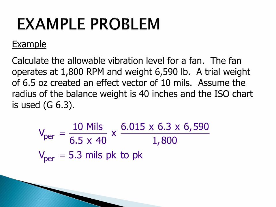
Example
Calculate the allowable vibration level for a fan. The fan operates at 1,800 RPM and weight 6,590 lb. A trial weight of 6.5 oz created an effect vector of 10 mils. Assume the radius of the balance weight is 40 inches and the ISO chart is used (G 6.3).
per
per
10 Mils 6.015 x 6.3 x 6,590V x
6.5 x 40 1,800
V 5.3 mils pk to pk