Embed Size (px)
Citation preview
APL MATERIALS 5, 074108 (2017)
Piezoelectric peptide-based nanogenerator enhancedby single-electrode triboelectric nanogenerator
Vu Nguyen, Steve Kelly, and Rusen Yanga
Department of Mechanical Engineering, University of Minnesota, Minneapolis,Minnesota 55455, USA
(Received 14 March 2017; accepted 5 May 2017; published online 19 May 2017)
Peptide has recently been demonstrated as a sustainable and smart material for piezo-electric energy conversion. Although the power output was improved compared toother biomaterials, the use of a piezoelectric device alone can only capture the energyfrom the minute deformation in materials. In comparison, the triboelectric effect canconvert mechanical energy from large motion. Consequently, utilizing both piezoelec-tric and triboelectric effects is of significant research interest due to their complemen-tary energy conversion mechanisms. Here we demonstrated a hybrid nanogeneratorthat combined a peptide-based piezoelectric nanogenerator with a single-electrode tri-boelectric nanogenerator. Our device structure enabled the voltage and current outputsof each individual type of nanogenerator to be superposed in the hybrid nanogener-ator, producing overall constructive outputs. The design of our device also enableda simplified configuration of hybrid nanogenerator. This study is important not onlyfor the enhancement of peptide-based piezoelectric device but also for the futuredesign of hybrid piezoelectric and triboelectric nanogenerators. © 2017 Author(s).All article content, except where otherwise noted, is licensed under a CreativeCommons Attribution (CC BY) license (http://creativecommons.org/licenses/by/4.0/).[http://dx.doi.org/10.1063/1.4983701]
Piezoelectric bio-inspired materials have emerged as promising candidates for electromechani-cal energy conversion thanks to their biocompatibility, versatility, and mild synthesis processes.1–3
Among them, diphenylalanine (FF) peptide has attracted increasing research interest due to itsstrong piezoelectric coefficient and the ability to produce parallel electrical dipoles.2,4,5 Althoughthe nanogenerator (NG) fabricated from FF peptide showed significant improvement in performancecompared to other bio-inspired materials, new techniques to enhance the output are needed to expandits applications.
Due to their complementary effects in mechanical energy harvesting, piezoelectric nanogener-ators (PENGs) have been proposed to be hybridized with triboelectric nanogenerators (TENGs).6–9
While PENG converts the deformation of the piezoelectric material into electricity, TENG convertsrelative motion into electricity through contact electrification and electrostatic induction.10 The avail-able ambient mechanical energy can be provided to the NG in two forms, i.e., relative motion andmaterial deformation, so it is advantageous to combine a TENG and PENG. Among the possibleoperation modes of TENG, the two-electrode modes were most often used to demonstrate hybriddevices.6,9,11 These TENG modes require two separate conductive electrodes to be stacked with thePENG. However, in applications where the thickness of the hybrid NG is restricted, it can be moreadvantageous to use the single-electrode mode of TENG in combination with the PENG due to thereduced number of layers and their structural similarity.7
Here we investigated the output enhancement of an FF-based PENG through hybridization witha single-electrode TENG. The piezoelectric FF microrod array was fabricated using our recentlydeveloped method. The integration with a single-electrode TENG and the resultant electricity gener-ation process were studied. Our work can serve as a guideline for the future hybrid design of a PENGand TENG.
aAuthor to whom correspondence should be addressed. Electronic mail: [email protected]
2166-532X/2017/5(7)/074108/5 5, 074108-1 © Author(s) 2017
074108-2 Nguyen, Kelly, and Yang APL Mater. 5, 074108 (2017)
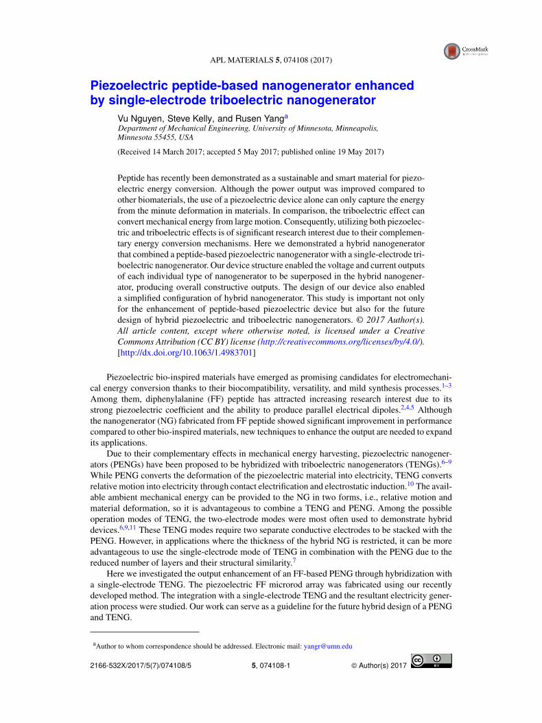
First, an FF microrod array was fabricated using our previously reported epitaxial growth pro-cess.2,12 Briefly, the crystalline seed film with vertically aligned domains was obtained by placingan amorphous FF gel film in vigorously circulated moist air. This step was followed by putting theseed film in a saturated FF water solution at 55 °C for epitaxial growth. Throughout this process, anelectric field was applied to obtain uniform polarization. The size of the obtained microrod array is1.25 × 1.25 cm2. Figures 1(a) and 1(b) show the Scanning Electron Microscope (SEM) pictures ofthe obtained vertical microrod array on a gold-coated silicon substrate. The piezoelectricity of themicrorods was confirmed by Piezoresponse Force Microscopy (PFM) (Asylum MFP 3D). The PFMprobe (ASYELEC-01, Asylum Research) was vibrated at 20 kHz, far from contact resonance to avoidsignal amplification. The applied voltage to the probe was swept from 2 V to 10 V as it scanned onthe tip of the microrod. The corresponding probe vibration amplitudes were recorded in Figure 1(c).The effective piezoelectric coefficient d33 of the microrods can be estimated from the slope of thefitted line as about 11.4 pm/V, verifying the good piezoelectricity of the obtained FF array.
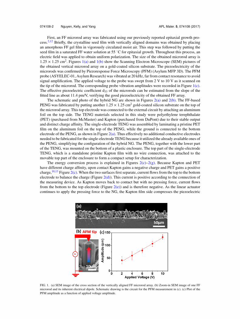
The schematic and photo of the hybrid NG are shown in Figures 2(a) and 2(b). The FF-basedPENG was fabricated by putting another 1.25 × 1.25 cm2 gold-coated silicon substrate on the top ofthe microrod array. This top electrode was connected to the external circuit by attaching an aluminumfoil on the top side. The TENG materials selected in this study were polyethylene terephthalate(PET) (purchased from McMaster) and Kapton (purchased from DuPont) due to their stable outputand distinct charge affinity. The single-electrode TENG was assembled by laminating a pristine PETfilm on the aluminum foil on the top of the PENG, while the ground is connected to the bottomelectrode of the PENG, as shown in Figure 2(a). Thus effectively no additional conductive electrodesneeded to be fabricated for the single-electrode TENG because it utilized the already available ones ofthe PENG, simplifying the configuration of the hybrid NG. The PENG, together with the lower partof the TENG, was mounted on the bottom of a plastic enclosure. The top part of the single-electrodeTENG, which is a standalone pristine Kapton film with no wire connection, was attached to themovable top part of the enclosure to form a compact setup for characterization.
The energy conversion process is explained in Figures 2(c)–2(g). Because Kapton and PEThave different charge affinity, upon contact Kapton gains a negative charge and PET gains a positivecharge,10,13 Figure 2(c). When the two surfaces first separate, current flows from the top to the bottomelectrode to balance the charge (Figure 2(d)). This current is positive according to the connection ofthe measuring device. As Kapton moves back to contact but with no pressing force, current flowsfrom the bottom to the top electrode (Figure 2(e)) and is therefore negative. As the linear actuatorcontinues to apply the pressing force to the NG, the Kapton film side compresses the piezoelectric
FIG. 1. (a) SEM image of the cross section of the vertically aligned FF microrod array. (b) Zoom-in SEM image of one FFmicrorod and its inherent electrical dipole. Schematic drawing is the circuit for the PFM measurement in (c). (c) Plot of thePFM amplitude as a function of applied voltage amplitude.
074108-3 Nguyen, Kelly, and Yang APL Mater. 5, 074108 (2017)
FIG. 2. (a) Schematic of the structure of the hybrid NG and the polarity of the measurement connection. (b) Photograph ofthe real hybrid NG with a compact acrylic enclosure. Scale bar is 1 cm. ((c)-(g)) Energy conversion process of the hybrid NG.
FF microrods and current continues to flow to the top electrode due to the electrical dipole created inthe piezoelectric FF microrod under pressure. When the pressing force is released, the FF microrodsare no longer compressed and the current flows back to the bottom electrode (Figure 2(g)). TheKapton film is then separated from the PET, as in Figure 2(d) and current continues to flow back tothe bottom electrode to complete one cycle. As a result, the hybrid device can harvest energy fromboth the significant movement of the top layer of the TENG and minute deformation in piezoelectricmaterials caused by the pressing force.
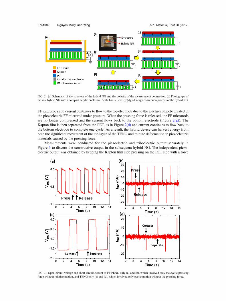
Measurements were conducted for the piezoelectric and triboelectric output separately inFigure 3 to discern the constructive output in the subsequent hybrid NG. The independent piezo-electric output was obtained by keeping the Kapton film side pressing on the PET side with a force
FIG. 3. Open-circuit voltage and short-circuit current of FF PENG only (a) and (b), which involved only the cyclic pressingforce without relative motion, and TENG only (c) and (d), which involved only cyclic motion without the pressing force.
074108-4 Nguyen, Kelly, and Yang APL Mater. 5, 074108 (2017)
larger than zero, which prevented the separation of the two layers of the TENG. This process isrepresented by the steps in Figures 2(f) and 2(g). The triboelectric output was independently obtainedby moving the Kapton film to just in contact with the PET film with an insignificant pressing forceand then separating them. This process is similar to the steps in Figures 3(a)–3(d). Voc and Isc fromthe piezoelectric nanogenerator were about 0.7 V and 30 nA, respectively, under an applied forceof 50 N. The average charge, calculated by the area under the current peak, was 406 pC. Theseresults were consistent with the reported output of FF-based NG.2 Voc and Isc from the triboelectricnanogenerator were about 1.6 V and 20 nA, respectively, with the average charge of 875 pC. Thelower peak current but higher charge of the TENG part was due to the relatively slow motion of theKapton film to reduce the impact on the FF microrod array upon contact. The current direction andvoltage polarity of the triboelectric output were in the same direction as the piezoelectric output.Two outputs were thus expected to be superimposed constructively as both contact and pressing areperformed.
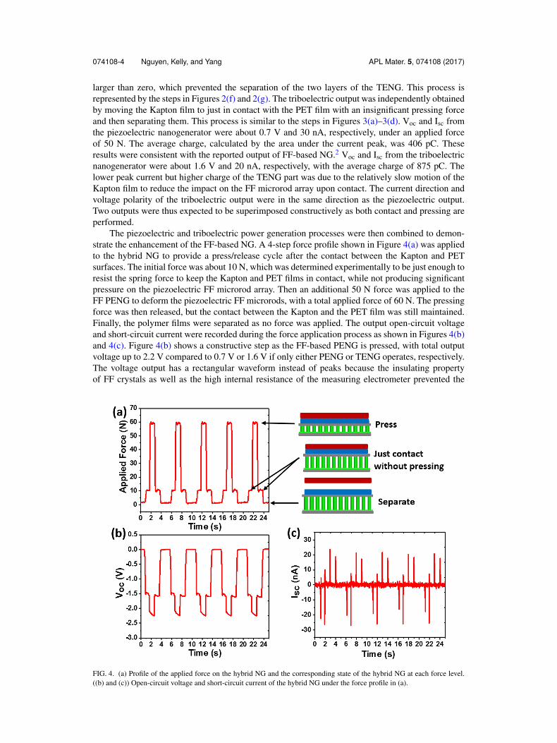
The piezoelectric and triboelectric power generation processes were then combined to demon-strate the enhancement of the FF-based NG. A 4-step force profile shown in Figure 4(a) was appliedto the hybrid NG to provide a press/release cycle after the contact between the Kapton and PETsurfaces. The initial force was about 10 N, which was determined experimentally to be just enough toresist the spring force to keep the Kapton and PET films in contact, while not producing significantpressure on the piezoelectric FF microrod array. Then an additional 50 N force was applied to theFF PENG to deform the piezoelectric FF microrods, with a total applied force of 60 N. The pressingforce was then released, but the contact between the Kapton and the PET film was still maintained.Finally, the polymer films were separated as no force was applied. The output open-circuit voltageand short-circuit current were recorded during the force application process as shown in Figures 4(b)and 4(c). Figure 4(b) shows a constructive step as the FF-based PENG is pressed, with total outputvoltage up to 2.2 V compared to 0.7 V or 1.6 V if only either PENG or TENG operates, respectively.The voltage output has a rectangular waveform instead of peaks because the insulating propertyof FF crystals as well as the high internal resistance of the measuring electrometer prevented the
FIG. 4. (a) Profile of the applied force on the hybrid NG and the corresponding state of the hybrid NG at each force level.((b) and (c)) Open-circuit voltage and short-circuit current of the hybrid NG under the force profile in (a).
074108-5 Nguyen, Kelly, and Yang APL Mater. 5, 074108 (2017)
unintentional discharge. Figure 4(c) shows four current peaks in one force application cycle whichare also in the constructive direction as the force is applied or withdrawn. The directions of the outputcurrent were consistent with the process explained in Figures 2(d)–2(g), verifying the constructiveenergy conversion mechanism of the hybrid NG.
In conclusion, we have demonstrated a hybrid NG structure that utilized a single-electrode TENGto provide constructive additional voltage and current outputs to the FF-based PENG. The design ofour hybrid NG was simple because the addition of a single-electrode TENG to the existing FF-basedPENG did not require additional conductive electrodes. Although Kapton and PET were selected inthis study, the TENG materials can still be optimized to best suit a specific application. Since theKapton film was not connected to the circuit, it could be designed to be a part of the environment ofthe hybrid NG, which could simplify the fabrication process and reduce the dimension of the hybridNG. Our study can serve as a guideline for the design of a future FF-based device as well as futurehybridization between a PENG and TENG.
We sincerely thank the support from NSF (No. ECCS-1150147) and the 3M company. Theelectron microscopy images were obtained in the Characterization Facility, University of Minnesota,which receives partial support from NSF through the MRSEC program. Part of the device fabricationwas performed in the Minnesota Nano Center, a part of the NSF-funded National NanotechnologyCoordinated Infrastructure.
1 B. Y. Lee, J. Zhang, C. Zueger, W.-J. Chung, S. Y. Yoo, E. Wang, J. Meyer, R. Ramesh, and S.-W. Lee, Nat. Nanotechnol.7, 351 (2012).
2 V. Nguyen, R. Zhu, K. Jenkins, and R. Yang, Nat. Commun. 7, 13566 (2016).3 D.-M. Shin, H. J. Han, W.-G. Kim, E. Kim, C. Kim, S. W. Hong, H. K. Kim, J.-W. Oh, and Y.-H. Hwang, Energy Environ.
Sci. 8, 3198 (2015).4 A. Kholkin, N. Amdursky, I. Bdikin, E. Gazit, and G. Rosenman, ACS Nano 4, 610 (2010).5 S. Vasilev, P. Zelenovskiy, D. Vasileva, A. Nuraeva, V. Y. Shur, and A. L. Kholkin, J. Phys. Chem. Solids 93, 68 (2016).6 W.-S. Jung, M.-G. Kang, H. G. Moon, S.-H. Baek, S.-J. Yoon, Z.-L. Wang, S.-W. Kim, and C.-Y. Kang, Sci. Rep. 5, 9309
(2015).7 M. Han, X. Chen, B. Yu, and H. Zhang, Adv. Electron. Mater. 1, 1500187 (2015).8 P. Bai, G. Zhu, Y. S. Zhou, S. Wang, J. Ma, G. Zhang, and Z. L. Wang, Nano Res. 7, 990 (2014).9 M. Han, X.-S. Zhang, B. Meng, W. Liu, W. Tang, X. Sun, W. Wang, and H. Zhang, ACS Nano 7, 8554 (2013).
10 Z. L. Wang, ACS Nano 7, 9533 (2013).11 Y. Zi, L. Lin, J. Wang, S. Wang, J. Chen, X. Fan, P. K. Yang, F. Yi, and Z. L. Wang, Adv. Mater. 27, 2340 (2015).12 V. Nguyen, K. Jenkins, and R. Yang, Nano Energy 17, 323 (2015).13 F.-R. Fan, Z.-Q. Tian, and Z. L. Wang, Nano Energy 1, 328 (2012).