Embed Size (px)
Citation preview

PiGRRL ZeroCreated by Ruiz Brothers
Last updated on 2018-04-03 03:16:19 AM UTC
25566778
11111212
1313
141414
1415
1516171919202020212122
232324
25252626
2727
282828292930
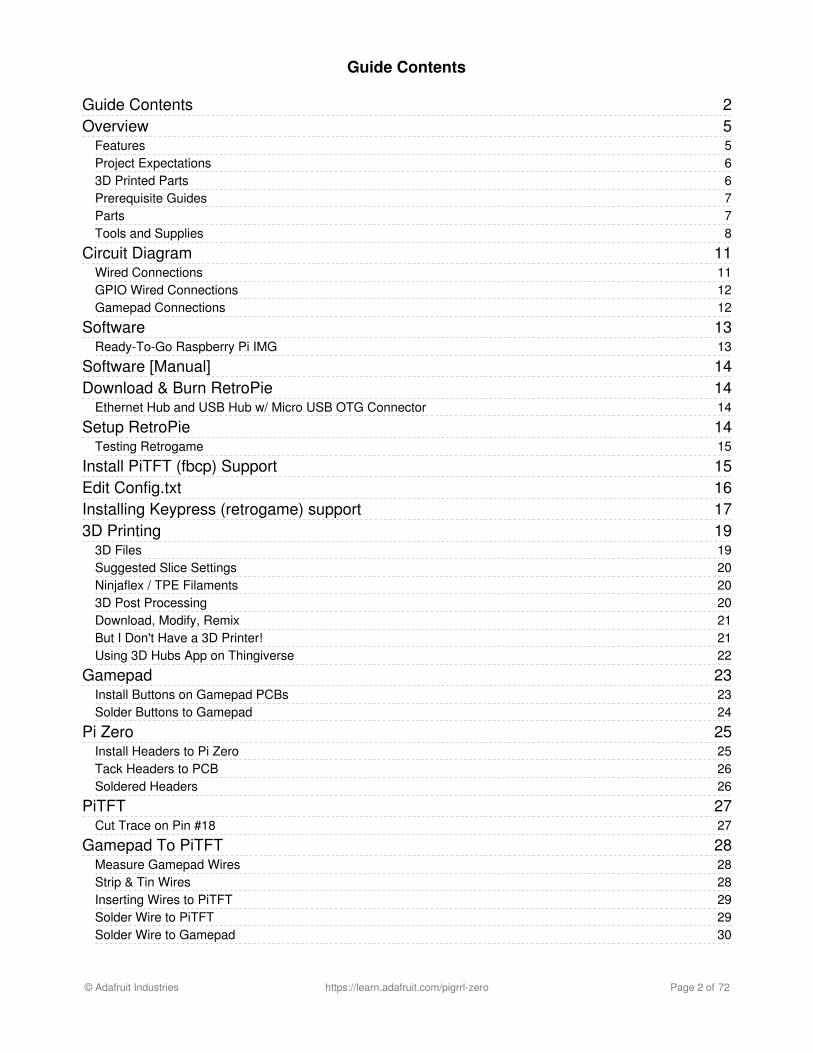
Guide Contents
Guide ContentsOverview
FeaturesProject Expectations3D Printed PartsPrerequisite GuidesPartsTools and Supplies
Circuit DiagramWired ConnectionsGPIO Wired ConnectionsGamepad Connections
SoftwareReady-To-Go Raspberry Pi IMG
Software [Manual]Download & Burn RetroPie
Ethernet Hub and USB Hub w/ Micro USB OTG Connector
Setup RetroPieTesting Retrogame
Install PiTFT (fbcp) SupportEdit Config.txtInstalling Keypress (retrogame) support3D Printing
3D FilesSuggested Slice SettingsNinjaflex / TPE Filaments3D Post ProcessingDownload, Modify, RemixBut I Don't Have a 3D Printer!Using 3D Hubs App on Thingiverse
GamepadInstall Buttons on Gamepad PCBsSolder Buttons to Gamepad
Pi ZeroInstall Headers to Pi ZeroTack Headers to PCBSoldered Headers
PiTFTCut Trace on Pin #18
Gamepad To PiTFTMeasure Gamepad WiresStrip & Tin WiresInserting Wires to PiTFTSolder Wire to PiTFTSolder Wire to Gamepad
© Adafruit Industries https://learn.adafruit.com/pigrrl-zero Page 2 of 72

303132
333334343535
36363738394040
41414142424343
44444444454545
46464646474748495051515253545556575859
60
Wired GamepadTest Gamepad ConnectionsWired Gamepads
PiTFT To Pi ZeroInstall PiTFT to Pi ZeroConnecting PiTFT to Pi ZeroSolder PiTFT to Pi ZeroSoldered PiTFT to Pi ZeroGamepad Ground Connections
PowerPowerBoost ConnectionsPrep Slide SwitchSolder Wires to Slide SwitchConnect Switch to PowerBoost 1000CPowerBoost WiresConnect PowerBoost to Raspberry Pi
USBUSB AdaptersRemove Legs from USB Female JackPrep USB PinsUSB WiresConnect Wires to USB OTG AdapterConnect Wires to Female USB Jack
Shoulder ButtonsShoulder ButtonsMeasure Shoulder Button WiresShoulder Button WiresConnect Wires to ButtonsConnect Wires to PiTFTGround Shoulder Buttons
Mounting ComponentsConnect USB OTG AdapterTest Final CircuitVerify TestMount PowerBoost 1000CMount Slide SwitchMount Female USB JackInstall BatteryScrews and WashersInstall ActuatorsInstall PiTFT to CaseFasten ScrewsGamepad PCB Mounting HolesMount Gamepad PCBsMount Shoulder ButtonsFinal Circuity CheckClose CaseInstall Shoulder ActuatorsFinal Build
Usage & Extras
© Adafruit Industries https://learn.adafruit.com/pigrrl-zero Page 3 of 72
606060606061
626263656668686868686868
696969697172
PiTFT ButtonsConnecting to WiFiUploading ROMsUSB PortAudio AdapterExiting a ROM/Game
RetroPie: Improving Emulator PerformanceOverclockingChoosing an Alternate EmulatorInstalling Additional EmulatorsUpdating Emulators to Latest VersionsTroubleshooting RetroPie and retrogameretrogame Related Troubleshooting
Some of my buttons/controls aren’t working!NONE of my buttons/controls are working!My controls only work if there’s also a USB keyboard plugged in!Retrogame doesn’t work with my optical buttons!I ran Adafruit’s retrogame installer script and rebooted, and now the keyboard and network are unresponsive!
RetroPie Related TroubleshootingMy controls work in the EmulationStation UI, but not in one or more specific emulators!The ROM files I have worked in a different emulator before, but aren’t working in RetroPie!Installing RetroPie PackagesAccessing Alternate EmulatorsMore RetroPie Help
© Adafruit Industries https://learn.adafruit.com/pigrrl-zero Page 4 of 72

Overview
You've seen PiGRRL, Super Game Pi, PiGRRL Pocket, PiGRRL 2 and now... it's time for PiGRRL Zero!
In this tutorial we'll turn the elusive $5 Raspberry Pi Zero into portable game console!
Features
Retropie 3.7 Emulation Station: SNES, NES, SEGA, N64, and many many more!14 Buttons, including D-Pad, L & R shoulder, Start/Select, A, B, X, Y and two extras.2.2" Adafruit PiTFT 320x240 Color DisplayLandscape portable console format
The USB female jack allows you to add any peripherals to the Raspberry Pi Zero, such as a WiFi or Bluetooth adapter,USB keyboard or mouse, USB Audio Adapter or USB Hub.
PLEASE BE AWARE - THIS IS NOT AN EASY/BEGINNER PROJECT! This project is for experienced makers,with successful soldering and Raspberry Pi projects. We DO NOT guarantee you will be able to build thisproject sucessfully!
© Adafruit Industries https://learn.adafruit.com/pigrrl-zero Page 5 of 72

Project Expectations
The difficulty of this project is low-medium. There is wiring and soldering involved, but no PCB hacking or sawing likeour previous builds. We think this is a great project for makers who have a little bit of Pi and 3D printing experience, orare first time makers with a lot of energy and willingness to learn! This tutorial will walk you through all the steps of theassembly and takes about weekend to accomplish.
3D Printed Parts
You'll need to 3D print the enclosure and buttons for this project. If you don't have access to one, 3DHubs.com is a
© Adafruit Industries https://learn.adafruit.com/pigrrl-zero Page 6 of 72

great option - simply download the STL files, upload them and choose a local hub to print and ship them to you!
Prerequisite Guides
If you're new to soldering, definitely check out Collin's Lab: Soldering. You'll learn the basics of soldering and how fun itcan be!
Learn how-to solder. Collin's Lab: Soldering
Parts
You'll need the following components to make this project.
1x Adafruit PiTFT 2.2"1x Raspberry Pi Zero1x PowerBoost 1000C1x 2000mAh Battery10x 6mm Tactile Buttons1x Slide Switch1x USB Mini Wifi Adapter1x Tiny OTG Adapter - USB Micro to USB2x PiGRRL Zero Gamepad PCBs1x 2x20-pin Strip Dual Male Header
The following parts are optional.
1x USB Audio Adapter
© Adafruit Industries https://learn.adafruit.com/pigrrl-zero Page 7 of 72

Gamepad PCB on OSH Park
https://adafru.it/nyA
Tools and Supplies
The following tools and supplies will help you build this project.
3D Printer + FilamentSoldering Iron + Solder30AWG + 26AWG WireHelping Third Hands / PanaviseHeat ShrinkGlue / Mounting TackWire Stripper / CuttersFiling Tool / Hobby Knife6x #4-40 3/8 (M3 x 9.5mm)machine screws
© Adafruit Industries https://learn.adafruit.com/pigrrl-zero Page 8 of 72

© Adafruit Industries https://learn.adafruit.com/pigrrl-zero Page 9 of 72

© Adafruit Industries https://learn.adafruit.com/pigrrl-zero Page 10 of 72

Circuit Diagram
Wired Connections
The diagram above depicts the connections for the power, audio and gamepad. Use this as a reference for wiring thecomponents. Note, the length of wires and position of components are not exactly how the circuit will be - it’s just adiagram to show connections.
PLEASE BE AWARE - THIS IS NOT AN EASY/BEGINNER PROJECT! This project is for experienced makers,with successful soldering and Raspberry Pi projects. We DO NOT guarantee you will be able to build thisproject sucessfully!
{ 18, KEY_LEFT }, // Left{ 24, KEY_RIGHT }, // Right{ 5, KEY_DOWN }, // Down{ 6, KEY_UP }, // Up{ 12, KEY_Z }, // A{ 13, KEY_X }, // B{ 16, KEY_A }, // X{ 19, KEY_S }, // Y{ 20, KEY_Q }, // L{ 21, KEY_W }, // R{ 17, KEY_ESC }, // TFT 17{ 22, KEY_LEFTCTRL }, // TFT 22 SELECT{ 23, KEY_ENTER }, // TFT 23 START{ 27, KEY_4 }, // TFT 27
© Adafruit Industries https://learn.adafruit.com/pigrrl-zero Page 11 of 72

GPIO Wired Connections
Follow the table above to reference which buttons to wire to the GPIO. The numbers on the left represent thecorresponding GPIO number (NOT the pin number).
Gamepad Connections
When the PiTFT is flipped over, the connections are reversed. This diagram references the connections from the backof the PiTFT and Gamepad PCBs. This is most likely how you will wire the buttons to the pins on PiTFT. The colorsmatch with each corresponding button and GPIO number.
Gamepad PCB Update! Pins have been updated. Please reference the wiring diagram below.
© Adafruit Industries https://learn.adafruit.com/pigrrl-zero Page 12 of 72

Software
Ready-To-Go Raspberry Pi IMG
Click the button below to download the PiGRRL Zero img. You'll need to burn this to an SD card (2 GB minimum) usinga image burning tool, like the ones listed in the guide
Once the img has been burnt to a blank SDCard, insert it into the Raspberry Pi Zero. The image is preloaded with tools,emulators, some games and preconfigured buttons for the gamepad controls. It will only work with the PiTFT (Soplugging in an HDMI monitor might not display anything).
Download PiGRRL Zero IMG
https://adafru.it/rne
After first boot, you'll need to expand the filesystem to fill the SD card. This requires having a keyboard attachedtemporarily (either through a USB hub or a USB-A-to-micro adapter).
From the EmultationStation GUI, press “F4” to exit to a Linux command prompt. Then type “sudo raspi-config”. Thevery first option in this menu is “Expand Filesystem.” Run that command. Afterward, tab over to the “Finish” buttonand reboot when prompted.
PLEASE BE AWARE - THIS IS NOT AN EASY/BEGINNER PROJECT! This project is for experienced makers,with successful soldering and Raspberry Pi projects. We DO NOT guarantee you will be able to build thisproject sucessfully!
The image does not work with the Raspberry Pi Zero W – If you're using the Pi Zero W, you will need tomanually setup the software.
© Adafruit Industries https://learn.adafruit.com/pigrrl-zero Page 13 of 72

Software [Manual]
Download & Burn RetroPie
Game emulation is handled by a package called RetroPie. It’s a complete Linux distribution designed specifically forrunning classic games on Raspberry Pi.
Download the current version from the RetroPie web site, then write this to an SD card using Etcher or similar software.
We’ll then make some modifications to tune this for the PiGRRL’s buttons and small display.
Setup will require an HDMI monitor, USB keyboard and a network connection (a USB WiFi or Ethernet dongle, forexample). This is best done before the Pi is enclosed in the PiGRRL case. If you have a spare Raspberry Pi boardaround, that’s an ideal option…you could prepare the software on that system and then move the card over to thePiGRRL.
A USB/Ethernet hub + a Keyboard is ideal
Setup RetroPie
Insert the RetroPie card to your Pi, attach monitor and keyboard (and Ethernet, if networking that way), then power thesystem from a USB power source (a USB phone charger or a powered USB hub can usually work). The system willautomatically reboot once (it needs this to make use of the whole SD card), then on second boot it will ask to configurethe game controls…
The PiGRRL buttons don’t work yet; this is normal. For initial setup, use the USB keyboard to select the D-paddirections (arrow keys), Start, Select, A and B keys. For anything else, just hold down the space bar or other key to skipthat item . Don't worry, we'll re-do the keymap later once we've finished assembly! When finished, you’ll see agraphical interface called Emulation Station where you’ll select games and other options.
Let’s get this Raspberry Pi on the network first. If WiFi, from the main EmulationStation screen, access the RetroPiesettings using whatever key you’ve assigned as the “A” button. You’ll see WIFI in this list:
We recommend you go with the ready-to-download image rather than trying to do this by hand, but here'sdetails if you're interested!
Ethernet Hub and USB Hub w/ Micro USB OTG Connector
$14.95IN STOCK
ADD TO CART
© Adafruit Industries https://learn.adafruit.com/pigrrl-zero Page 14 of 72

Here you can select your WiFi network name and enter
a password. It’s not beautiful, but gets the job done.
Select “Exit” when done to return to the
EmulationStation UI…
With networking enabled, we can now access the remaining software needed for the PiGRRL 2 experience. There area couple ways to do this…
BEST: Use an ssh terminal client to log into the Raspberry Pi at retropie.local This is recommended, as you can just copy-and-paste the commands that follow. The default name andpassword are “pi” and “raspberry,” respectively.OR: Press “F4” to exit EmulationStation for a command-line prompt (works, but you’ll need to type thesecommands exactly).
Testing Retrogame
Once the SD card is finished, insert it into the Pi and boot it up. You should get emulation station to boot automatically.Configure your controls using a keyboard and test out the games in the ports section to make sure everything isrunning properly.
Install PiTFT (fbcp) Support
This first sequence configures the system for the PiTFT display:
Select the “PiGRRL Zero” option, which sets up various system parameters to match this project.
cdcurl -O https://raw.githubusercontent.com/adafruit/Raspberry-Pi-Installer-Scripts/master/pitft-fbcp.shsudo bash pitft-fbcp.sh
© Adafruit Industries https://learn.adafruit.com/pigrrl-zero Page 15 of 72

Answer “NO” to the reboot question…
Edit Config.txt
For optimized speed and decent audio from the emulators, may want to to tweak some settings in the config.txt file, foroverclocking/gpu configuration
run sudo nano /boot/config.txt and add/edit the end of the file:
© Adafruit Industries https://learn.adafruit.com/pigrrl-zero Page 16 of 72

Also, set the audio to 3.5mm with sudo raspi-config (under Advanced/Audio)
Installing Keypress (retrogame) support
let’s take care of this second script, which enables the PiGRRL buttons:
Again, select the “PiGRRL Zero” option. When finished, now you can reboot when prompted.
gpu_mem=44disable_audio_dither=1overscan_scale=1#gpu_mem_256=128#gpu_mem_512=256#gpu_mem_1024=256dtoverlay=pitft22,rotate=270,speed=60000000,fps=40display_rotate=0hdmi_cvt=320 240 60 1 0 0 0arm_freq=1000core_freq=500sdram_freq=450over_voltage=6
cdcurl -O https://raw.githubusercontent.com/adafruit/Raspberry-Pi-Installer-Scripts/master/retrogame.shsudo bash retrogame.sh
© Adafruit Industries https://learn.adafruit.com/pigrrl-zero Page 17 of 72

After rebooting, the HDMI monitor may display a “no signal” message. This is normal. Not all monitors can handle theresolution setting we’re using. Once the PiTFT is wired up, that will be the primary display.
Also, after the system is assembled with the PiTFT and controls, you’ll need to re-do the controller setup. This mightwait ’til all the parts are assembled in the case.
From the main EmulationStation screen, press whatever
key was assigned to the “Start” button to access the
main menu. You’ll find an option here for “CONFIGURE
INPUT.”
Go through the control setup process again using the
PiGRRL buttons now instead of the keyboard; assign the
D-pad directions, Start and Select buttons, A, B, X and Y.
For anything else, hold down a key or button to skip it.
© Adafruit Industries https://learn.adafruit.com/pigrrl-zero Page 18 of 72

3D Printing
3D Files
Download the STLs by clicking on the button below. The table references the file names, their use and recommendmaterial.
Pinshape Download
https://adafru.it/nAe
Thingiverse Download
https://adafru.it/nqB
Cults3D Download
https://adafru.it/nAf
case-bot.stl 1x Enclosure top half PLA
case-top.stl 1x enclosure bottom half PLA
washer.stl 2x washers for bottom mounting holes of PiTFT PLA
dpad.stl 1x Directional pad Ninjaflex / TPE
buttons.stl 1x Actions buttons Ninjaflex / TPE
pitft-buttons.stl 1x Buttons for PiTFT display Ninjaflex / TPE
shoulder-button.stl 2x shoulder buttons Ninjaflex / TPE
© Adafruit Industries https://learn.adafruit.com/pigrrl-zero Page 19 of 72

YouMagine Download
https://adafru.it/nAq
Suggested Slice Settings
Each printer and slicing software is different. Although we can't possible test each printer profile out, we do howeverhave some suggested settings (these are for a 3D printer with a 0.4mm nozzle and 1.75mm filament).
Extrusion Multiplier: 1.00Extrusion Width: 0.48mmRetraction Dist. 1mmRetraction Speed: 30mm/sLayer Height: 0.2mmTop / Bottom Layers: 4Outline/ Perimeter Shells: 2First Layer Height: 100%First Layer Width: 100%First Layer Speed: 50%Default Printing Speed: 60mm/s - 90mm/sMovement Speed: 90mm/s - 150mm/sSolid Infill Underspeed: 50%Interior Infill: 25%Outline Overlap: 25%Infill Width: 100%Extruder Temp: 220cHeated Bed: 0c - 60c
Ninjaflex / TPE Filaments
Since TPE filament is a rubber based material, the slice settings will need to be slightly different. Typically you need toprint hotter, slower, and completely disable retraction.
Extruder Temp: 230c - 240cDefault Printing Speed: 30mm/sMovement Speed: 40mm/sRetraction: OFF
3D Post Processing
It's a good idea to thoroughly inspect your parts after 3D printing. Check to see if there's any defects in the surfacesand walls of each part.
Test fitting the parts to see if the tolerances are balanced. Do the DPad and action buttons fit into the holes? Can thetwo halves snap fit together? Are the standoffs strong, or do they easily break apart? These are all dependent on yourslice settings.
There's a total of 8 standoff's with mounting holes. It's a good idea to tap these in order to create the threads beforemounting components. They're sized for #4-40 machine screws (or M3).
If you're interested and giving the surface a smooth finish, you can optional sand the parts down and apply Smooth-OnXTC3D coating.
© Adafruit Industries https://learn.adafruit.com/pigrrl-zero Page 20 of 72

Download, Modify, Remix
The design is open source, so you can make modifications and remix the design. It was designed in Autodesk Fusion360. You can download the source file in your choice of file format (IGS, STEP, SAT, etc.)
Download Source
https://adafru.it/nqC
But I Don't Have a 3D Printer!
That's totally OK, you can still buy the parts and have them shipped to you! You can use a service like 3D Hubs to 3Dprint all of the parts for you. Just download all of the STL files from our Thingiverse page and upload them to theirwebsite.
© Adafruit Industries https://learn.adafruit.com/pigrrl-zero Page 21 of 72

Using 3D Hubs App on ThingiverseThe easiest way to do this is to use the "Print" button on
the Thingiverse page. Then, click on the Launch App
button to automatically load the STL files into 3D Hubs.
From there, you can select colors, materials and enter
your shipping address. A total price will let you know
how much the parts will cost. A list of local hubs will
appear and you can select which ever looks good to
you. Hubs have different prices, ratings, reviews, and
sample photos so you can narrow down your choice.
© Adafruit Industries https://learn.adafruit.com/pigrrl-zero Page 22 of 72

Gamepad
Install Buttons on Gamepad PCBsLet's start by setting up our buttons. Insert each
button on the side of the PCB with the "BUTTON PAD"
writing. Make sure the orientation of the legs on the
buttons are positioned with the pins. Push them into the
holes so they're all the way in, flush with the surface of
the PCB.
© Adafruit Industries https://learn.adafruit.com/pigrrl-zero Page 23 of 72

Solder Buttons to GamepadFlip the PCB over and secure it to a Panavise Jr. or
Helping Third Hands. Then, add solder to all of the pins.
Repeat this proceedure for the second gamepad PCB.
© Adafruit Industries https://learn.adafruit.com/pigrrl-zero Page 24 of 72

Pi Zero
Install Headers to Pi ZeroThe Raspberry Pi Zero ships with no headers installed
on the GPIO. Insert the 2x20 (or two 1x20) headers into
the GPIO like shown the photo. The black plastic bit
should be on top of the PCB.
© Adafruit Industries https://learn.adafruit.com/pigrrl-zero Page 25 of 72

Tack Headers to PCBUse tape or mounting tack to hold the header onto the
PCB. Then, secure the PCB to a pair of Helping Third
Hands or a Panavise Jr. This will make it easier to solder.
Flip the PCB over and solder all of the pins to the GPIO.
Soldered HeadersInspect each connection and ensure there are no cold
solder joints. If you find it difficult to apply solder to the
pins, try tinning the tip of the soldering iron.
© Adafruit Industries https://learn.adafruit.com/pigrrl-zero Page 26 of 72

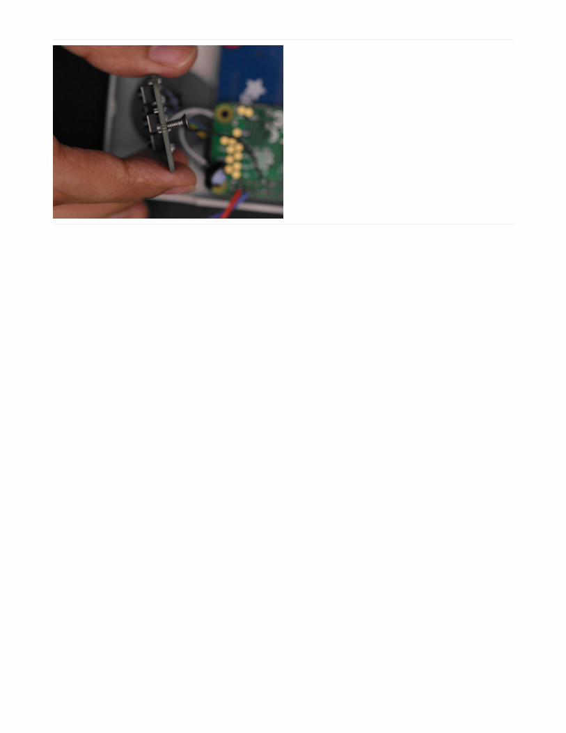
PiTFT
Cut Trace on Pin #18In order to properly use Pin #18 (left button) we'll need to
cut the trace on the back of the PiTFT. Using a sharp
hobby knife, you can score in between the pads to cut
the trace.
I recommend testing the connection with a multimeter
using the continuity mode. Press the probes onto the
pads. If the multimeter beeps, then the trace isn't
completely cut. It's best to ensure the trace is cut now
then later in the build.
© Adafruit Industries https://learn.adafruit.com/pigrrl-zero Page 27 of 72

Gamepad To PiTFT
Measure Gamepad WiresGrab one of the gamepads and position it close to the
PiTFT (In the photo, we're doing the DPAD first). We
need to measure a piece of wire to see how long it
needs to be for the first button (The left button on the
DPAD). I recommend making it slightly longer so we
have some slack and wiggle room.
In the photo, I have inserted a long wire into Pin #18 on
the back of the PiTFT. By flipping the PiTFT over, I can
see which pin is labeled.
Once we've determined a good length for our first
connection, cut the piece of wire.
Strip & Tin WiresUse wire strippers to remove 5mm of insulation from
each tip. Then, apply a bit of solder to the tips to tin
them. This will prevent the stranded wires from fraying
and make it easier to solder to the pads.
Gamepad PCB Update! Please reference the wiring diagram below with blue PCB. Purple PCBs are slightlydifferent (Pins B3 and B4 have been flipped).
© Adafruit Industries https://learn.adafruit.com/pigrrl-zero Page 28 of 72

Inserting Wires to PiTFTTo make wiring a bit easier, I suggest inserting the wire
into the corresponding pin (#18 for the left button in this
case) and threading it through until the tip from the
other end is touching the hole. Then, bend the tip at a
right angle so it can be held in place.
Solder Wire to PiTFTNow that the wire is in place, you can solder the
connection to secure it.
© Adafruit Industries https://learn.adafruit.com/pigrrl-zero Page 29 of 72

Solder Wire to GamepadNow we can apply some solder to the header pins on
the Gamepad PCB. I suggest tinning the pads on the
header of the PCB before soldering wires to them so it's
easier.
Although the photo shows the wire orientated from the
top, I recommend positioning the wire from the bottom.
This will make securing the PCB to the 3D print case
easier.
Wired GamepadRepeat this process for the rest of the buttons, up, down
and right. Each button requires a different length of wire.
I recommend referencing the wiring diagram closely and
double checking each wire is in the correct positon.
Also, try doing one wire at a time to prevent any
confusion.
© Adafruit Industries https://learn.adafruit.com/pigrrl-zero Page 30 of 72

Test Gamepad ConnectionsIt's a good idea to test your connections! Using a
multimeter in continuity mode, you can probe the
header pins on the PiTFT and gamepad to see if the
connections have continuity - You'll hear a "BEEP" sound
if the connection is solid.
Wired GamepadsWith patience and persistance, you'll end up with two
gamepads wired up to the PiTFT.
This part of the build is the most time consuming, so try
not to rush it. Once complete, feel free take a break :-)
In the next page, we'll solder the Pi Zero to the PiTFT
and sort out the other components.
© Adafruit Industries https://learn.adafruit.com/pigrrl-zero Page 31 of 72

© Adafruit Industries https://learn.adafruit.com/pigrrl-zero Page 32 of 72

PiTFT To Pi Zero
Install PiTFT to Pi ZeroNow we can insert the PiTFT to the Pi Zero. You'll want
to group the wires from the gamepad so they aren't
kinked. Slowly guide the pins from the GPIO header on
the Pi Zero and seat them through the pins on the
PiTFT.
PLEASE BE AWARE - THIS IS NOT AN EASY/BEGINNER PROJECT! This project is for experienced makers,with successful soldering and Raspberry Pi projects. We DO NOT guarantee you will be able to build thisproject sucessfully!
© Adafruit Industries https://learn.adafruit.com/pigrrl-zero Page 33 of 72

Connecting PiTFT to Pi ZeroLook at the HDMI and USB ports on the Pi and make
sure they're flush with the back of the PiTFT. The wires
from the gamepad should be behind the ports.
When you seat the GPIO header from the Pi to the
PiTFT, try not to fully press them together. If you do,
you'll see the Pi Zero PCB will be slightly angled. Try to
keep the two PCBs as straight as possible.
Solder PiTFT to Pi ZeroTrim the pins from the header of the Pi Zero so they're
slightly taller than the pins of the PiTFT. This will make it
easier to apply solder. Once they're all trimmed down,
go ahead an solder all of the pins! Take your time and
be sure the solder joints are solid.
© Adafruit Industries https://learn.adafruit.com/pigrrl-zero Page 34 of 72

Soldered PiTFT to Pi ZeroDouble check each pin and ensure they're nicely
soldered.
Gamepad Ground ConnectionsNow is a good time to add ground connections for the
two gamepad PCBs. We can add these to the back of
the Pi Zero. Measure and cut two pieces of wires. Solder
them to the available ground pads on the gamepad PCB.
Then, connect those to the back of the Pi.
© Adafruit Industries https://learn.adafruit.com/pigrrl-zero Page 35 of 72

Power
PowerBoost ConnectionsGrab the bottom half of the enclosure and sit the
PowerBoost 1000C on top of the four standoffs near the
bottom left. Then, insert the slide switch into the bottom
center. These two components should just snap fit into
the case.
Next, we need to measure two 26AWG wires for
connecting the slide switch. They'll be connected to the
EN and GND pins on the PowerBoost 1000C. Once
you've sorted out a good length for them, strip and tin
the ends of each wire.
Don't use a PowerBoost 500C! The photo shows the incorrect component. You really want the power of the1000C
© Adafruit Industries https://learn.adafruit.com/pigrrl-zero Page 36 of 72

Prep Slide SwitchNow that we have our wires sorted out, we can prep the
slide switch. First, we don't need three leads, so remove
one using a pair of flush snips (it can be any of the leads
on the far left or right, but not the middle). Then, trim the
remaining two leads to about half their length. Now we
can tin them by applying some solder.
© Adafruit Industries https://learn.adafruit.com/pigrrl-zero Page 37 of 72

Solder Wires to Slide SwitchWith the leads tinned, solder both wires to the two
leads. Pieces of shrink tubing will insulate the exposed
connections. Simply apply heat to "shrink" the tubing.
© Adafruit Industries https://learn.adafruit.com/pigrrl-zero Page 38 of 72

Connect Switch to PowerBoost 1000CSolder one wire to the EN pin on the PowerBoost 1000C
and the other to GND.
Now you can plug in the JST connector from the
2000mAh battery into the JST port on the PowerBoost
1000C. The switch will allow you to power it on and off.
The blue LED will light up indicating it's powered on.
© Adafruit Industries https://learn.adafruit.com/pigrrl-zero Page 39 of 72

PowerBoost Wires Next, we need to sort out a set of two 26AWG wires for
connecting the PowerBoost 1000C to the Raspberry Pi
Zero. We can do this like we did for the slide switch.
Once we have a good length, cut, strip and tin the wires.
Then, solder them to the postive+ and negative+ pads
on the PowerBoost 1000C.
Connect PowerBoost to Raspberry PiNow we can solder the positive and negative
connections from the PowerBoost 1000C to the GPIO
pins on the back of the Raspberry Pi Zero. Reference
the photo for the right pins. Red is positive, and blue is
negative.
© Adafruit Industries https://learn.adafruit.com/pigrrl-zero Page 40 of 72

USB
USB AdaptersOK, now it's time to work on the USB adapters. Grab the
USB OTG adapter and the USB female port (this came
with the PowerBoost 1000C). We need to create a set of
4 wires that will connect these two components
together.
This is necessary for connecting peripherals to the
Raspberry Pi such as WiFi adapter, USB Audio adapter
and more.
Remove Legs from USB Female JackUse a pair of flush snips to cut off the legs from the
female USB jack. These prevent the port from being
able to fit into the case. They're normally used to secure
the jack to pins on a PCB, but since we're mounting to it
the case, we don't need them.
© Adafruit Industries https://learn.adafruit.com/pigrrl-zero Page 41 of 72

Prep USB PinsNext, we need to bend the four connectors on the USB
female jack so they're right-angled. As they are now, it
wouldn't fit in the case. Use a pair of flush pliers to
carefully bend each connector. You'll want to be
cautious while doing this. The connectors MUST NOT
touch the metal housing - if it does, it'll short out the
connection. You can optional remove the metal back
piece from the USB jack.
USB WiresWe'll need to make a set of four wires for connecting our
USB adapters together. I found 13cm to be a good
length. Like we've done previously, strip and tin the
ends of each wire. A piece of heat shrink tubing will
keep these four wires together.
© Adafruit Industries https://learn.adafruit.com/pigrrl-zero Page 42 of 72

Connect Wires to USB OTG AdapterMost microUSB cables follow the same color coded
wiring.
Black / Blue – GND
Red – VCC 5V
Green – USB Data -
White – USB Data +
Follow the photo to reference which wire to connect to
the correct pin. Tinning the four pins on the USB OTG
adapter will make it easier to solder the wires to them.
Connect Wires to Female USB JackFollowing a similar method, connect the four wires to
the pins on the Female USB jack. Note the colors are
reversed. That's because we have the USB jack fliped.
Make sure you familarize yourself with the top and
bottom of the USB jack. The bottom has the white
plastic bit.
© Adafruit Industries https://learn.adafruit.com/pigrrl-zero Page 43 of 72

Shoulder Buttons
Shoulder ButtonsNow it's time to work on the shoulder buttons. The two
buttons I used in this project are 2-terminal versions that
come with extra long legs. The ones included in the
kit have four legs. You only need to use two of them.
Measure Shoulder Button WiresLayout the two buttons and plan out the lengths of each
wire. The L and R shoulder buttons will need to be
connected to the last two remaining pins on PiTFT (#20
and #21) and the remaining ground pins on the
Gamepad PCBs.
Shoulder Button WiresOnce you've measured each wire, we'll prep them by
striping and tinning the tips. You'll also want to tin the
leads on each button.
© Adafruit Industries https://learn.adafruit.com/pigrrl-zero Page 44 of 72

Connect Wires to ButtonsSolder the wires to the terminals on each button.
Connect Wires to PiTFTConnecting the left shoulder button to the PiTFT is a
little tricky because it needs to be threaded through the
PiTFT and Raspberry Pi. Using the similar method we did
when connecting the gamepad PCB wires to the PiTFT,
the tinned tip of the wire should be able to poke through
pin #20. Once it is, solder it in place. The right shoulder
button is much easier to connect since pin #21 is close
to the edge.
Ground Shoulder ButtonsWith the two buttons connected to the PiTFT, solder the
remaining connection to the ground pins on the
gamepad PCB.
© Adafruit Industries https://learn.adafruit.com/pigrrl-zero Page 45 of 72

Mounting Components
Connect USB OTG AdapterBefore mounting the components, go ahead and plug in
the micro USB OTG adapter to the Raspberry Pi.
Test Final CircuitOK, now is a great time to test the circuit. Make sure the
PiGRRL Zero IMG has been properly burnt to the SD
card and inserted into the Raspberry Pi. "Flip" the switch
and the PiTFT should turn on. The Pi will take about a
minute to boot up.
The controls are premapped so you can test the
gamepad PCBs. Try a play test with one of the games in
the PORTS section. Use the "A" button to select. To exit
a game, hold down the two middle buttons (select and
start) on the PiTFT.
Verify Test
If you find something off or doesn't work as expected, feel free to post your questions or concerns in the AdafruitForums.
If everything works as expected, feel free to move onto the final steps!
© Adafruit Industries https://learn.adafruit.com/pigrrl-zero Page 46 of 72

Mount PowerBoost 1000CLet's start with the PowerBoost. This is mounted to the
bottom half of the enclosure, near the bottom right. The
microUSB port should be pointing towards the opening.
Simply lay the PCB over the standoffs and press it down
so the pegs are seated into the mounting holes.
Mount Slide SwitchThe slide switch can be installed into the bottom half of
the case by inserting it at an angle.
© Adafruit Industries https://learn.adafruit.com/pigrrl-zero Page 47 of 72

Mount Female USB JackSimilar to the slide switch, you'll need to insert the
female USB jack at an angle. A slight amount of force is
required to snap fit the housing of the USB jack into the
opening.
© Adafruit Industries https://learn.adafruit.com/pigrrl-zero Page 48 of 72

Install BatteryThere isn't a dedicated "holder" for the battery, but a
good location for the battery is near the top center. I
suggest using either double-sided tape or mounting tack
to keep the battery in place.
© Adafruit Industries https://learn.adafruit.com/pigrrl-zero Page 49 of 72

Screws and WashersWe'll need two #4-40 3/8 flat Phillips machine screws to
install the PiTFT to the case. 3D printed washers will
help prevent the screws from poke through the
enclosure. Fasten each screw into these washers.
© Adafruit Industries https://learn.adafruit.com/pigrrl-zero Page 50 of 72

Install ActuatorsGrab the top half of the enclosure and insert the DPad,
action buttons and 4-grouped menu buttons.
Install PiTFT to CasePosition the full circuit into the top half of the case. Line
up the mounting holes of the PiTFT with the standoffs in
the center of the case.
© Adafruit Industries https://learn.adafruit.com/pigrrl-zero Page 51 of 72

Fasten ScrewsInsert one machine screw into one of the bottom
mounting holes of the PiTFT. Hold the PCB down to the
case while fastening the screw through the PCB and
standoff until the washer is flush with the surface.
Repeat for the second machine screw.
© Adafruit Industries https://learn.adafruit.com/pigrrl-zero Page 52 of 72
Gamepad PCB Mounting HolesThere's two mounting holes on each gamepad PCB
needs to be tapped. Using a #4-40 machine screw, you
can create the threads by slowly fastening through the
hole. I suggest doing this before mounting the PCB to
the stand offs on the case - It'll make it easier.
© Adafruit Industries https://learn.adafruit.com/pigrrl-zero Page 53 of 72

Mount Gamepad PCBsWith the mounting holes tapped, position the PCB over
the standoffs on the case and hold it in place. Then,
fasten screws through the mounting holes. Do not fully
fasten the screws into the standoffs – They only need to
be fastened half way. The screw may poke through the
case if it's fully fasten through.
© Adafruit Industries https://learn.adafruit.com/pigrrl-zero Page 54 of 72

Mount Shoulder ButtonsA small piece of mouting tack will keep the shoulder
buttons in place. Near the top of the gamepad standoffs
is a holder for the shoulder buttons. Insert the shoulder
button into the holder with the actuator pointing towards
the top.
© Adafruit Industries https://learn.adafruit.com/pigrrl-zero Page 55 of 72

Final Circuity Check
Now is a good time to check all of your work. Are all of the wires connected? Are all the components secured? If youfind some of the wires are too long, it's fine to trim them short.
© Adafruit Industries https://learn.adafruit.com/pigrrl-zero Page 56 of 72

Close CaseCarefully join the two halves of the case and press them
firmly together. Ensure all of the wires are inside the
enclosure to prevent kinking any of the wires.
© Adafruit Industries https://learn.adafruit.com/pigrrl-zero Page 57 of 72

Install Shoulder Actuators The shoulder buttons printed in TPE filament is easy to
install. Squeeze the actuator and press it into the
openings. Hold the two halves together while installing
the actuators to prevent the case from coming apart.
© Adafruit Industries https://learn.adafruit.com/pigrrl-zero Page 58 of 72

Final Build
Congratulations! You've finished building the PiGRRL Zero! Take a moment to test out all of the button acutators with aplay test. If eveything works as expect, great! If not, please feel free to post any questions or concerns in the AdafruitForums.
© Adafruit Industries https://learn.adafruit.com/pigrrl-zero Page 59 of 72

Usage & ExtrasPlease see notes on the “Software” page about expanding the filesystem to utilize the whole SD card. This is notdone automatically.
PiTFT Buttons
The four buttons the PiTFT display are mapped to the following (start from left to right):
1. Exit - Escape (GPIO 17)2. Select - Left Control (GPIO 22)3. Start - Enter/Return (GPIO 23)4. Not Mapped - 4 (GPIO 27)
Connecting to WiFi
Before connecting a WiFi adapter, you'll want to use a USB hub so you can connect a USB keyboard necessary fortyping your WiFi password. Then, connect a WiFi adapter into the USB hub.
Go to the RetroPie section in Emulation Station and choose "Configure WiFi". Select "1 Connect to WiFi network" withthe Enter key. Use the up and down buttons of the DPad to highlight your network and the Enter key to choose. Typein your WiFi password and use the Enter key to submit. Your Pi's IP address will display in the top of the WiFi Menu.Choose "Cancel" using the Enter key to exit the "Configure WiFi" menu.
Uploading ROMs
You'll need to get the Pi on your WiFi network in order to connect to it. Use your desktop computer and your preferedSFTP client to connect.
IP Address - example: 10.1.10.XXXUsername: piPassword: raspberry
Go to the following directory to upload ROMs
/home/pi/RetroPie/roms
Upload your ROMs to the proper emulator folder (ie. nes, snes, gb, etc.)
USB Port
The USB port can be used to connect peripheral such as a USB hub, keyboard, WiFi, Bluetooth or audio adapter.
Audio Adapter
A USB Audio Adapter can be used to output audio. We suggest using the one linked in the BOM, as it's proven to workwith the Raspberry Pi. There's no need to configure the audio since the ready-to-go PiGRRL Zero image has itpreinstalled.
Please note, USB 3.0 hubs can be problematic the Raspberry Pi Zero.
© Adafruit Industries https://learn.adafruit.com/pigrrl-zero Page 60 of 72

To change the audio output level, go to the "RetroPie" section in emulation station and select "Configure AudioSettings", then choose "4 Mixer - adjust output volume" using the "enter / return" key (3rd button from left) on the PiTFT.From here, you can use the DPAD up or down buttons to adjust the audio levels. Press the "exit" button (far left button)on the PiTFT to save and exit "ALSA Mixer".
Exiting a ROM/Game
To quit a game and go back to the Emulation Station screen, press and hold the "Start" and "Select" buttons at thesame time.
© Adafruit Industries https://learn.adafruit.com/pigrrl-zero Page 61 of 72

RetroPie: Improving Emulator PerformanceOn single-core Raspberry Pi boards like the Model A+ and Pi Zero, emulation speed is sometimes less than stellar…thescreen may update like molasses, or sound may be choppy. Let’s look at some ideas to fight back…
All of these methods require a USB keyboard attached.
The directions shown here are for RetroPie 4.1, but the same general ideas apply to other versions and possibly evenother emulation packages, the steps will just be different.
Overclocking
Most Raspberry Pi boards can handle some overclocking — running the processor slightly faster than its “official”speed. Too fast though, and the system can become unstable and crash. Due to manufacturing variances, every singleboard is slightly different in this regard…you’ll need to do some experimentation to find the fastest reliable setting foryour specific board. Restart after making any changes and try running some games for several minutes to really putthe system through its paces.
You can access the raspi-config utility from the RetroPie
configuration screen, or press “F4” to exit to a command
line and run “sudo raspi-config” manually.
raspi-config is keyboard-based, mostly using the arrows
and enter keys; arcade controls, if connected, probably
won’t have the intended effect.
Different Pi models offer different overlock settings. On
the Model B+ being tested here, the “Medium” setting
seems quite reliable. Other board types may overclock
automatically and there’s nothing to adjust here.
© Adafruit Industries https://learn.adafruit.com/pigrrl-zero Page 62 of 72

If you’re using a PiTFT display, the “core” frequency setting should not exceed 300 MHz; the display will glitch andmay not work at all. So avoid the higher overclock settings if using one of these screens, or manually edit the file/boot/config.txt to fine-tune various system frequencies individually.
Choosing an Alternate Emulator
When launching a game, there’s a brief moment when
it’s possible to access some launch options…
When you see this “launching” screen, press the space
bar (or any other key that generates an actual keycode…
not a “meta” key like shift or control).
This brings up a menu…similar to raspi-config, it
operates with the keyboard, not arcade buttons.
The first option lets you select an alternate emulator
program (if available). For example, RetroPie 4.1 includes
two different NES emulators: lr-fceumm (the default) and
lr-nestopia. Different emulators make tradeoffs with
regard to performance and “accuracy” of the emulation.
© Adafruit Industries https://learn.adafruit.com/pigrrl-zero Page 63 of 72

Try an alternative and see how it performs (use the
“Launch” option).
The selection you make will “stick” — it is not necessary
to use this menu every time, unless you want to switch
back to the original emulator choice. There’s also an
option to use an alternate emulator only for specific
ROMs, if you have different needs for different games.
The above steps are fairly quick and easy. If they meet your needs, consider the job done! If it’s still not quite theperformance you need, the situation gets more involved…
These next steps require a network connection. On a Model A+ or Pi Zero, that usually requires a USB hub and anEthernet or WiFi adapter, along with some configuration (the RetroPie 4.1 configuration menu includes WiFi setup).Alternately, if you have a spare Model B+ around, that’s easy to get on an Ethernet network…move the SD card over
© Adafruit Industries https://learn.adafruit.com/pigrrl-zero Page 64 of 72

there for setup, then move it back to the target system when done.
Installing Additional Emulators
Some “bleeding edge” emulators might offer better
performance than the stock options provided by
RetroPie. As with the “Alternate Emulators” above, it
sometimes comes with a tradeoff in accuracy (hence
their non-inclusion), so you’ll need to experiment and
decide if it’s worth it.
From the RetroPie configuration screen, select “RetroPie
Setup,” which switches to another of these keyboard-
based menus.
Select “Manage packages,” then either “Manage
optional packages” or “Manage experimental
packages.” You’ll get a list of various emulators and/or
games that aren’t normally installed by default. lr-quicknes was an optional package for NES emulation…
it’s faster than the others…too fast, in fact, so I ended up
not using it…but that’s all part of the experimentation
process.
Choose the “Install from binary” option to install the
selected package. Don’t bother with the “source”
option…it’s very time consuming and usually provides no
benefit.
© Adafruit Industries https://learn.adafruit.com/pigrrl-zero Page 65 of 72

Updating Emulators to Latest Versions
Sometimes you just need the newest-and-shiniest version of an installed emulator to provide the best availableperformance…
© Adafruit Industries https://learn.adafruit.com/pigrrl-zero Page 66 of 72

From the RetroPie configuration screen, select “RetroPie
Setup.” This brings up the keyboard-driven menu again.
Choose the “Update all installed packages” option to
make a sweep through the system that’ll update
everything to the latest release, including the kernel.
This system-wide update can be extremely time-
consuming…possibly an hour or so, depending on
processor and network speeds.
Even the default lr-fceumm on a non-overclocked Pi ran
great after updating!
If using a PiTFT display, think twice before trying this
option. Perhaps make a backup of your SD card first.
Kernel updates have been known to break PiTFT
support in some circumstances, and you’d have to start
all over.
© Adafruit Industries https://learn.adafruit.com/pigrrl-zero Page 67 of 72

Troubleshooting RetroPie and retrogameThis page documents the most common pitfalls encountered when making retro gaming projects, offering somesolutions and where to turn for further help.
There are some things we can fix and some we can’t…we’re not involved in RetroPie’s development, for example…butwe’ll try to point you in the right direction.
Most of the following troubleshooting steps will require a USB keyboard attached. Some require a networkconnection.
retrogame Related Troubleshooting
retrogame is our software that converts GPIO button actions into keyboard events. These are the problems we’re bestequipped to fix.
Some common things to check for any retrogame installation:
Confirm button/joystick wires go to the correct pins and to ground. A multimeter with a continuity beep function ishelpful for testing.The retrogame configuration file (/boot/retrogame.cfg) uses Broadcom pin numbers…these are not sequentialalong the GPIO header pins. This site has a nice reference chart (use the “BCM” numbers).Earlier versions of retrogame didn’t use a configuration file…you had to edit and compile the source code. That’sjust horrible. If you’re running an early version like that, this would be a good time to upgrade. See the InstallingRetrogame page.
Some of my buttons/controls aren’t working!
Check connections and configuration file pin numbers as explained above. (If some controls are responding,that’s an encouraging start…it at least means the code is running.)The key codes generated by retrogame might not be assigned to EmulationStation’s keyboard inputs; one orthe other will need to be changed. Either edit /boot/retrogame.cfg, or, from the EmulationStation main screen,press Start to access the main menu, then select “Configure Input” and proceed through each of the controls.
NONE of my buttons/controls are working!
Confirm that retrogame is actually running…either exit to the command line (F4) or log in using ssh, then use“ps -ef | grep retrogame” to check. If you used our installer script or one of our ready-made SD card images, itshould be started automatically on boot (added to /etc/rc.local).Confirm that the file “/etc/udev/rules.d/10-retrogame.rules” exists. Our installer script creates this file, but if youinstalled retrogame manually or from source, it may have been overlooked.
My controls only work if there’s also a USB keyboard plugged in!
Confirm that the file “/etc/udev/rules.d/10-retrogame.rules” exists. Our installer script creates this file, but if youinstalled retrogame manually or from source, it may have been overlooked.
Retrogame doesn’t work with my optical buttons!
Unfortunately, yes. retrogame only works with “passive” switches between a GPIO pin and ground (logiclow=pressed). It won’t work with switches that have the opposite logic level (high=pressed).
I ran Adafruit’s retrogame installer script and rebooted, and now the keyboard and network are unresponsive!
This can happen if you’re running an early Raspberry Pi (Model A or B) with the 26-pin GPIO header and select the
© Adafruit Industries https://learn.adafruit.com/pigrrl-zero Page 68 of 72

“Six buttons + joystick” option in the retrogame installer. That particular configuration is set up for our Arcade Packand newer (40 pin) Raspberry Pi boards. Some of the pin numbers referenced don’t exist on the older 26-pin headerand lead to trouble.
If this happens to you, not to worry. Power off the Pi and insert the SD card in a reader on a PC or Mac. Look for afile called retrogame.cfg…edit this file and change the pin numbers to match your specific controller wiring.
RetroPie Related Troubleshooting
RetroPie provides the actual emulation software and a nice user interface. As this is third-party code, the “depth” ofproblems we can troubleshoot is more limited, but here are some of the common issues we’ve seen and how toresolve them…
My controls work in the EmulationStation UI, but not in one or more specific emulators!
This can happen with certain emulators (usually older or more esoteric ones) that don’t use the libretro library.Among other things, libretro allows the global controller configuration to be used everywhere. There are a couple ofworkarounds that might help, but no guarantees…
You can rummage around in /opt/retropie/configs and look for a configuration file specific to theproblem emulator, then edit its keyboard layout to match your controls. The format of this file, if one evenexists, is likely specific to that one emulator, so you’ll need to do some research (Google search, etc.), it’s notsomething we can help out with.You can try hunting for an alternate emulator based on libretro, if there’s one available (see “Installing RetroPiePackages” below).
The ROM files I have worked in a different emulator before, but aren’t working in RetroPie!
This can happen if the ROM file format changes between versions of an emulator, or if two emulators for the samesystem use different formats.
Do some research (Google search, etc.) to see if this is the case. It’s possible there may be utilities to convertamong different ROM formats.Try installing an alternate emulator, if there’s one available (see “Installing RetroPie Packages” below).
A few emulators may require a “BIOS file” in order to function, but it’s not included with the software for legalreasons. This is something you’ll have to research and track down.
Installing RetroPie Packages
To add support for a system not present in RetroPie by
default, or to add an alternate emulator program for an
existing system, select “RetroPie Setup” from the
RetroPie menu. This brings up a text-menu-based
interface and will require a USB keyboard to navigate.
Select “Manage packages” and then one of the core,
main, optional or experimental selections…you’ll
probably want to navigate through each of them to see
what’s available, keeping in mind that each successive
category might be a little rougher around the edges.
Your best bet are packages whose names begin with
“lr-”. This means they’re built using libretro and the
© Adafruit Industries https://learn.adafruit.com/pigrrl-zero Page 69 of 72

control inputs should already work with what you have!
Other packages may require their own manual controller
setup, which can be a real nuisance.
When asked, select “Install from binary.” The sourceoption takes much longer and won’t provide any benefit
for the average user…only attempt that if you know you
need absolutely bleeding-edge code.
It’s totally valid to install multiple emulator packages that
handle the same type of system. Each might have
different performance or compatibility benefits, so it’s
worth testing your options. See “Accessing Alternate
Emulators” below.
© Adafruit Industries https://learn.adafruit.com/pigrrl-zero Page 70 of 72

Accessing Alternate Emulators
© Adafruit Industries https://learn.adafruit.com/pigrrl-zero Page 71 of 72

When you launch a game, you’ll briefly see this
nondescript launching message. You have a couple of
seconds to hit a button or key…
The first option in this configuration menu lets you
select a different emulator package for a given system
type…or even on an individual ROM-by-ROM basis, if
different games benefit from different emulation
software.
Test it out with. If you don’t like the results, next time you
launch that game you can access the configuration
menu again and restore the original selection.
More RetroPie Help
For issues not covered above, the best sources for RetroPie-specific help are the official documentation and forum onthe RetroPie web site:
RetroPie Documentation
RetroPie Forum
© Adafruit Industries Last Updated: 2018-04-03 03:16:19 AM UTC Page 72 of 72