Embed Size (px)
Citation preview
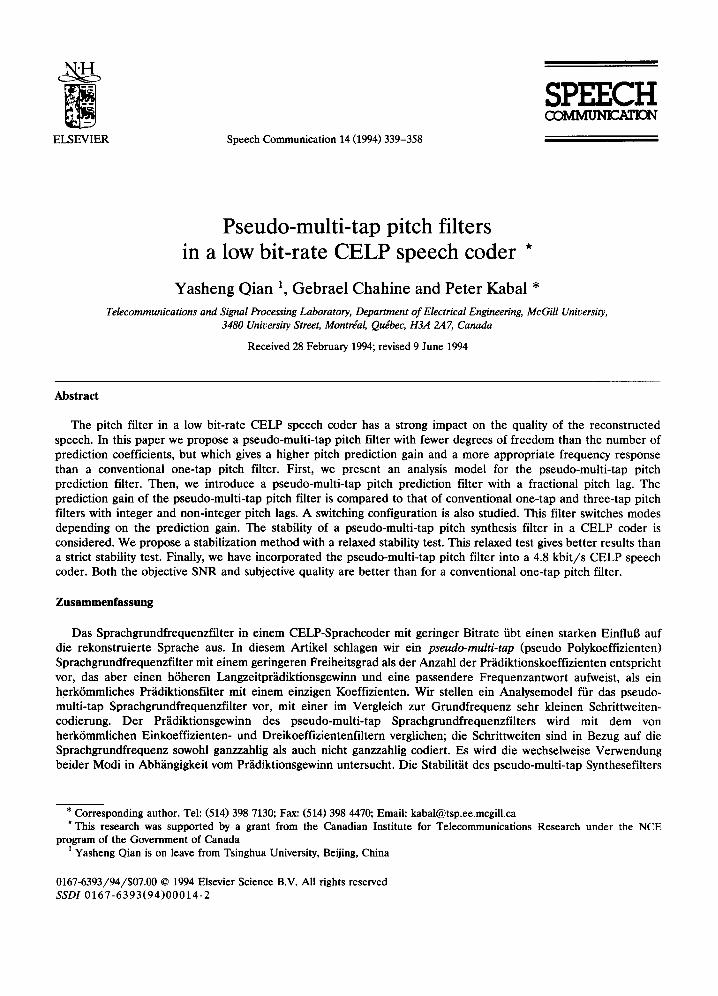
ELSEVIER Speech Communication 14 (1994) 339-358
SPEECH O~MbILrNr.K.~C~
Pseudo-multi-tap pitch filters in a low bit-rate CELP speech coder *
Yasheng Qian 1, Gebrael Chahine and Peter Kabal *
Telecommunications and Signal Processing Laboratory, Department of Electrical Engineering, McGill University, 3480 University Street, Montrgal, Quebec, H3A 2,47, Canada
Received 28 February 1994; revised 9 June 1994
Abstract
The pitch filter in a low bit-rate CELP speech coder has a strong impact on the quality of the reconstructed speech. In this paper we propose a pseudo-multi-tap pitch filter with fewer degrees of freedom than the number of prediction coefficients, but which gives a higher pitch prediction gain and a more appropriate frequency response than a conventional one-tap pitch filter. First, we present an analysis model for the pseudo-multi-tap pitch prediction filter. Then, we introduce a pseudo-multi-tap pitch prediction filter with a fractional pitch lag. The prediction gain of the pseudo-multi-tap pitch filter is compared to that of conventional one-tap and three-tap pitch filters with integer and non-integer pitch lags. A switching configuration is also studied. This filter switches modes depending on the prediction gain. The stability of a pseudo-multi-tap pitch synthesis filter in a CELP coder is considered. We propose a stabilization method with a relaxed stability test. This relaxed test gives better results than a strict stability test. Finally, we have incorporated the pseudo-multi-tap pitch filter into a 4.8 kb i t / s CELP speech coder. Both the objective SNR and subjective quality are better than for a conventional one-tap pitch filter.
Zusammenfassung
Das Sprachgrundfrequenzfilter in einem CELP-Sprachcoder mit geringer Bitrate iibt einen starken Einflul3 auf die rekonstruierte Sprache aus. In diesem Artikel schlagen wir ein pseudo-multi-tap (pseudo Polykoeffizienten) Sprachgrundfrequenzfilter mit einem geringeren Freiheitsgrad als der Anzahl der Pr/idiktionskoeffizienten entspricht vor, das aber einen h6heren Langzeitpr/idiktionsgewinn und eine passendere Frequenzantwort aufweist, als ein herkfmmliches Pr/idiktionsfilter mit einem einzigen Koeffizienten. Wir stellen ein Analysemodel ftir das pseudo- multi-tap Sprachgrundfrequenzfilter vor, mit einer im Vergleich zur Grundfrequenz sehr kleinen Schrittweiten- codierung. Der Pr/idiktionsgewinn des pseudo-multi-tap Sprachgrundfrequenzfilters wird mit dem von herk6mmlichen Einkoeffizienten- und Dreikoeffizientenfiltern verglichen; die Schrittweiten sind in Bezug auf die Sprachgrundfrequenz sowohl ganzzahlig als auch nicht ganzzahlig codiert. Es wird die wechselweise Verwendung beider Modi in Abh~ingigkeit vom Pr~idiktionsgewinn untersucht. Die Stabilit~it des pseudo-multi-tap Synthesefilters
* Corresponding author. Tel: (514) 398 7130; Fax: (514) 398 4470; Emaii: [email protected] * This research was supported by a grant from the Canadian Institute for Telecommunications Research under the NCE
program of the Government of Canada 1 Yasheng Qian is on leave from Tsinghua University, Beijing, China
0167-6393/94/$07.00 © 1994 Elsevier Science B.V. All rights reserved SSDI 0167-6393(94)00014-2
340 Y. Qian et al. / Speech Communication 14 (1994) 339-358
in einem CELP-Coder wird mit in Betracht gezogen. Wir schlagen eine Stabilisierungsmethode mit vermindertem Stabilit~itstest vor. Diese liefert bessere Resultate als der strenge Stabilit~itstest. Schliel31ich haben wir diese pseudo-multi-tap Sprachgrundfrequenzfilter in einem 4.8 kbit/s CELP-Sprachcoder eingebaut. Sowohl objektive SNR als auch subjektive Qualit~itsbeurteilung sind besser als in einem herk6mmlichen Einkoeffizienten- Langzeitpriidiktionsfilter.
Resum~
Le filtre ~ long-terme d'un codeur de parole CELP ~ bas-d4bit a une influence notable sur la qualit4 de la parole reconstruite. Dans cet article, nous proposons un pseudo-filtre de pr6diction ~ long terme ~ plusieurs coefficients qui poss~de moins de degr6s de libert4 que le nombre de coefficients de pr4diction, mais donne un meilleur gain en pr4diction ~ long-terme et une meilleure r6ponse en fr6quence qu'un filtre de pr6diction conventionnel ~ un seul coefficient. Nous proposons d'abord un pseudo-filtre de pr6diction ~ long-terme ~ plusieurs coefficients ~ d6codage fractionnel par rapport ~ la frfquence fondamentale. Le gain de pr6diction de ce filtre est compar6 ~ celui des filtres classiques ~ un seul coefficient et ~t trois coefficients, avec des d6calages entiers et fractionnaires. Nous d4crivons aussi une configuration autorisant leur commutation, celle-ci 6tant command4e par le gain de pr4diction. La stabilit4 du filtre lors de la phase de synth~se est 4tudi4e pour un codeur CELP: nous d4crivons une m&hode de stabilisation comprenant un test de stabilit4 affaiblie. Elle donne de meilleurs r6sultats qu'un test de stabilit6 stricte. Pour finir, nous avons incorpor6 notre pseudo-filtre de pr6diction ~ long terme ~ plusieurs coefficients dans un codeur CELP 4.8 kbit/s. Tant le rapport objectif signal ~ bruit que la qualit6 subjective ont 6t6 am61ior6s par rapport ~ ceux mesur6s avec un filtre de pr6diction ~ long terme conventionnel ~ un seul coefficient.
Key words: Speech coding; Pitch filter; Prediction gain; Fractional pitch lag; Stability
1. Introduction
A pitch filter cascaded with a formant filter is widely employed in many low bit-rate code-excited linear prediction (CELP) speech coders (Schroeder and Atal, 1989; Iyengar and Kabal, 1991; Campbell et al., 1990; Ramachandran and Kabal, 1989). In many cases, a one-tap pitch filter with integer or non-integer pitch lags is used. A three-tap pitch prediction filter provides a higher prediction gain than a one-tap pitch prediction filter. However, additional bits are required to adequately code the pitch filter coefficients.
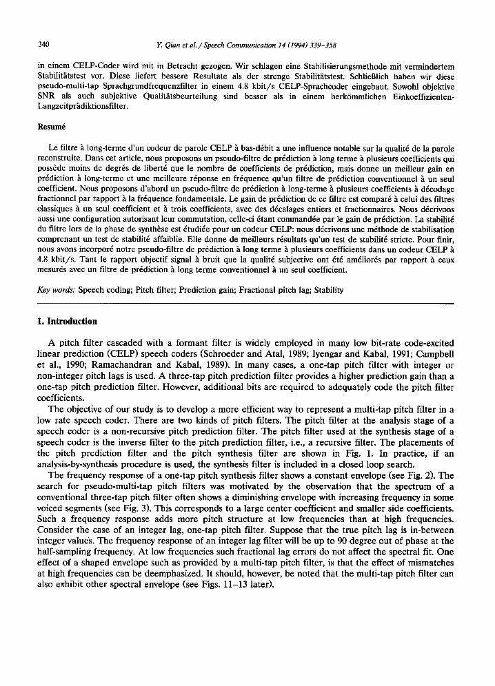
The objective of our study is to develop a more efficient way to represent a multi-tap pitch filter in a low rate speech coder. There are two kinds of pitch filters. The pitch filter at the analysis stage of a speech coder is a non-recursive pitch prediction filter. The pitch filter used at the synthesis stage of a speech coder is the inverse filter to the pitch prediction filter, i.e., a recursive filter. The placements of the pitch prediction filter and the pitch synthesis filter are shown in Fig. 1. In practice, if an analysis-by-synthesis procedure is used, the synthesis filter is included in a closed loop search.
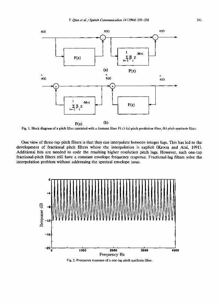
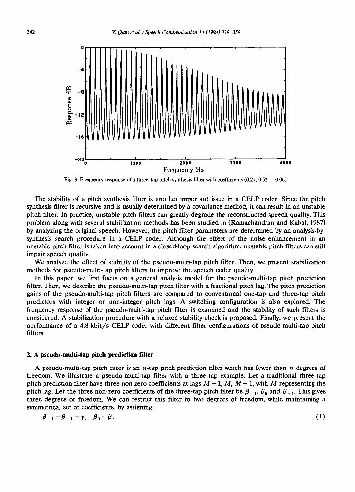
The frequency response of a one-tap pitch synthesis filter shows a constant envelope (see Fig. 2). The search for pseudo-multi-tap pitch filters was motivated by the observation that the spectrum of a conventional three-tap pitch filter often shows a diminishing envelope with increasing frequency in some voiced segments (see Fig. 3). This corresponds to a large center coefficient and smaller side coefficients. Such a frequency response adds more pitch structure at low frequencies than at high frequencies. Consider the case of an integer lag, one-tap pitch filter. Suppose that the true pitch lag is in-between integer values. The frequency response of an integer lag filter will be up to 90 degree out of phase at the half-sampling frequency. At low frequencies such fractional lag errors do not affect the spectral fit. One effect of a shaped envelope such as provided by a multi-tap pitch filter, is that the effect of mismatches at high frequencies can be deemphasized. It should, however, be noted that the multi-tap pitch filter can also exhibit other spectral envelope (see Figs. 11-13 later).
Y. Qian et al. / Speech Communication 14 (1994) 339-358 341
s(z) x(z) e(z)
F(z) i--~ ~ i z
(a) P(z) A A ^
e(z) x(z) s(z)
1 -M+i
i=~ ~ i z F(z)
P(z) Oa) Fig. 1. Block diagram of a pitch filter cascaded with a formant filter F(z): (a) pitch prediction filter, (b) pitch synthesis filter.
One view of three-tap pitch filters is that they can interpolate between integer lags. This has led to the development of fractional pitch filters where the interpolation is explicit (Kroon and Atal, 1991). Additional bits are needed to code the resulting higher resolution pitch lags. However, such one-tap fractional-pitch filters still have a constant envelope frequency response. Fractional-lag filters solve the interpolation problem without addressing the spectral envelope issue.
0
-12
- 1 6
-200 ] OlO0 20~00 30100 4000 Frequency Hz
Fig. 2. Frequency response of a one-tap pitch synthesis filter.
342 Y. Qian et al. / Speech Communication 14 (199,4) 339-358
- 4
-16
_:~Oi I , m , , 0 10'00 20 '00 30 '00 4 0 0 0
Frequency Hz
Fig. 3. Frequency response of a three-tap pitch synthesis filter with coefficients (0.27, 0.52, - 0.06).
The stability of a pitch synthesis filter is another important issue in a CELP coder. Since the pitch synthesis filter is recursive and is usually determined by a covariance method, it can result in an unstable pitch filter. In practice, unstable pitch filters can greatly degrade the reconstructed speech quality. This problem along with several stabilization methods has been studied in (Ramachandran and Kabal, 1987) by analyzing the original speech. However, the pitch filter parameters are determined by an analysis-by- synthesis search procedure in a CELP coder. Although the effect of the noise enhancement in an unstable pitch filter is taken into account in a closed-loop search algorithm, unstable pitch filters can still impair speech quality.
We analyze the effect of stability of the pseudo-multi-tap pitch filter. Then, we present stabilization methods for pseudo-multi-tap pitch filters to improve the speech coder quality.
In this paper, we first focus on a general analysis model for the pseudo-multi-tap pitch prediction filter. Then, we describe the pseudo-multi-tap pitch filter with a fractional pitch lag. The pitch prediction gains of the pseudo-multi-tap pitch filters are compared to conventional one-tap and three-tap pitch predictors with integer or non-integer pitch lags. A switching configuration is also explored. The frequency response of the pseudo-multi-tap pitch filter is examined and the stability of such filters is considered. A stabilization procedure with a relaxed stability check is proposed. Finally, we present the performance of a 4.8 kbit /s CELP coder with different filter configurations of pseudo-multi-tap pitch filters.
2. A pseudo-multi-tap pitch prediction filter
A pseudo-multi-tap pitch filter is an n-tap pitch prediction filter which has fewer than n degrees of freedom. We illustrate a pseudo-multi-tap filter with a three-tap example. Let a traditional three-tap pitch prediction filter have three non-zero coefficients at lags M - 1, M, M + 1, with M representing the pitch lag. Let the three non-zero coefficients of the three-tap pitch filter be/3_1,/30 and/3+1. This gives three degrees of freedom. We can restrict this filter to two degrees of freedom, while maintaining a symmetrical set of coefficients, by assigning
/3_1 = /3+1 = "y, / 3 0 = / 3 . ( 1 )
Y. Qian et al. / Speech Communication 14 (1994) 339-358 343
X(n) x (n)
Wd(n) ~ -M+I Z z I -I z
e (n) W
We(n)
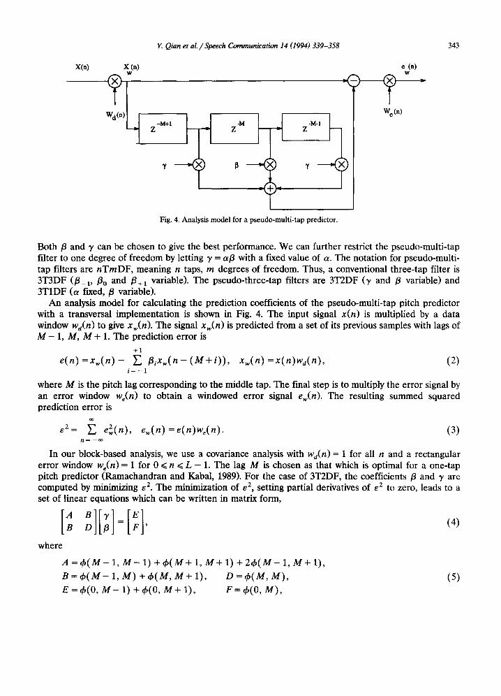
Fig. 4. Analysis model for a pseudo-multi-tap predictor.
Both/3 and 3' can be chosen to give the best performance. We can further restrict the pseudo-multi-tap filter to one degree of freedom by letting 3' = a/3 with a fixed value of a. The notation for pseudo-multi- tap filters are nTmDF, meaning n taps, m degrees of freedom. Thus, a conventional three-tap filter is 3T3DF (/3-1, /3o and /3+1 variable). The pseudo-three-tap filters are 3T2DF (3' and /3 variable) and 3TIDF (a fixed,/3 variable).
An analysis model for calculating the prediction coefficients of the pseudo-multi-tap pitch predictor with a transversal implementation is shown in Fig. 4. The input signal x(n) is multiplied by a data window Wd(n) to give xw(n). The signal xw(n) is predicted from a set of its previous samples with lags of M - 1, M, M + 1. The prediction error is
+1
e(n) = x w ( n ) - E /3ixw( n - ( M + i ) ) , Xw(n ) •x(n)wd(n), (2) i = - 1
where M is the pitch lag corresponding to the middle tap. The final step is to multiply the error signal by an error window We(n) to obtain a windowed error signal ew(n). The resulting summed squared prediction error is
oo
E2~ E 2 e~(n), e~(n)=e(n)w,(n). (3) n ~ - o o
In our block-based analysis, we use a covariance analysis with wd(n) = 1 for all n and a rectangular error window we(n) = 1 for 0 ~< n ~< L - 1. The lag M is chosen as that which is optimal for a one-tap pitch predictor (Ramachandran and Kabal, 1989). For the case of 3T2DF, the coefficients /3 and 3' are computed by minimizing e 2. The minimization of e 2, setting partial derivatives of e 2 to zero, leads to a set of linear equations which can be written in matrix form,
B 3'
where
A = ~ b ( M - 1, M - 1) + ~b(M+ 1, M + 1) + 2~b(M- 1, M + 1),
B=cb(M-1, M)+qb(M,M+I), D=~b(M,M), (5)
E = th(0, M - 1) + ~b(0, M + 1), F = ~b(0, M ) ,
344 Y. Qian et al. / Speech Communication 14 (199..4) 339-358
and ~b(i, j ) is defined as
¢ ( i , j ) = E W 2 e ( n ) x w ( n - i ) x w ( n - j ) , n ~ - o o
Using this formulation, we obtain/3op t and 7opt,
/3opt = ( A F - B E ) / / ( A D - n 2 ) , '~opt = (DE - n F ) / / ( h O - n 2 ) .
For the 3T1DF case,/3 is
a¢ (0 , M - 1) + 6(0, M) + a~b(0, M + 1)
/3opt = a2¢3 + ¢ ( M , M) + 2a~b 2 '
where
~b 3 - - - ¢ ( M - 1, M - 1) + 2 ~ b ( M - 1, M + l) + ¢ ( M + 1, M + 1),
~b2 = ¢ ( M - 1, M) + ¢ ( M , M + 1).
(6)
(7)
(8)
(9)
3. A fractional pseudo.multi.tap pitch prediction filter
The use of a fractional pitch lag has proved to be an accurate and efficient means to characterize speech periodicity in low bit-rate speech coders. Fractional pitch lags can also be used in pseudo-multi-tap pitch prediction filters. A non-integer pitch lag can be expressed as an integer number of samples plus a fraction. Let the pitch resolution be 1/D. The fractional part of the pitch lag can be expressed as l /D, where l = 0, 1 . . . . . D - 1 (0 ~< l / D < 0). The pseudo-multi-tap filter then acts on the interpolated samples, denoted by (t) x(t), xw (n - (M - 1)), w ~n - M), x~)(n - (M + 1)). The fractional delay is imple- mented using an interpolation filter. This filter delays the signal at the higher rate by an integer number of samples. The subsampled output of this filter is the desired fractionally delayed signal. Note that usually the filter coefficients are chosen to give x~)(n) = xw(n).
A polyphase filter structure (Croehiere and Rabiner, 1983) can be used to obtain the interpolated samples. For each fractional phase l, the impulse response p(t)(n) of the polyphase filter is obtained by sub-sampling an appropriate interpolating filter. In our case, we use an interpolation filter which is a Hamming-windowed ideal low-pass filter,
sin( ~ ( n - l /D) ) p(t)( n) = Wh( n -- l /D) , (10)
'rr( n - l /D)
where wh(n) is a Hamming window (centered at zero). We have chosen to have the same number of coefficients 2 I for each of the polyphase component
filters (! ~ 0). The resulting value which corresponds to the interpolated sample at n + l / D is given by 2 1 - 1
x~)( n ) = E P ( t ) ( k - I ) x w ( n - k ) , (11) k=O
where 21 is the number of the coefficients of the polyphase filter. The delay of the causal interpolation filter at the original sampling rate is I. The prediction error for a (fractional) pitch lag of M - l / D can be written as
1 2 1 - 1
e ( n ) = x w ( n ) - ~_~ ~_, f l i p ( O ( k - I ) x w ( n - ( M + i ) - k ) . (12) i = - - 1 k = 0
Y. Qian et al. / Speech Communication 14 (1994) 339-358 345
For the fractional pitch case, the optimal pitch predictor parameters can be obtained by minimizing e 2, as in the previous section, but with the covariance function appropriately modified. The new covariance functions with fractional delays are For i 4= 0,
oo 2 1 - 1 2 1 - 1
~., ~_~ p ( l ) ( k - I ) x w ( n - i - k ) ~, p ( l ) ( k - I ) x ~ ( n - j - k ) ; (13) n = - ~ k = O k = O
gb~t)( i, j) =
For i = O,
~bO)(O. j ) = oo 2 1 - 1
Xw(n ) ~ p ( O ( k - I ) x w ( n - j - k ) . (14) n= - ~ k = 0
For each ~b(°(i, j) and ~b~°(0, j), 1 ¢ 0, we have to convolve the impulse response of the polyphase filter and the weighted input samples to get the corresponding interpolated samples. In fact, each interpolated sample has to be manipulated many times to determine the best pitch lag M - I/D and the optimal prediction coefficients. The computation load is reduced if we first calculate the interpolated samples (t) Xw (n), for 1 = 1 . . . . . D - 1. Then, (13) and (14) become
o o o ~
4a(O( i, J) E x~)( n (')( ., ,--,--w , = - i ) x w , n - j ), th(t)(0, j ) = ~ x(O(nlr.(t)(n-j). (15) n ~ - ~ n ~ - ~
In order to identify the pitch lag M - l/D, we find the lag which minimizes the error for a one-tap pitch filter. We obtain the minimum square e r r o r ( e2 ) ( M - I / D ) corresponding to the optimal prediction coefficient/3op t for the given delay M - I/D.
(e2)(M-t/D)= ~" We(n) 2 x~(n) 2 - (¢( / ) (O 'M)) 2 n = - ~ (~b(O( M , M ) ) 2 (16)
The minimum of (e2) (M-t/D) corresponds to the maximum of (~b°)(0, M))2/(fb°)(M, M)) 2 over the range of allowable pitch lags.
4. Pitch predict ion gain
The pitch prediction gain is used to compare the performance of the pseudo-multi-tap pitch filters to conventional one-tap and three-tap pitch filters. The predictor gain PG (expressed in dB) is the ratio of the energy at the input of the predictor to that of the prediction error,
o o
E 2 Xw(n) - - o o
PGdB = 10 log n= e 2 (17)
In all cases, the pitch prediction filters are applied to the residual produced by a forward-adaptive formant prediction filter with 10 taps, updated every 160 samples. The pitch filters themselves are updated every 20 samples. The lag value chosen is that which is best for a one-tap pitch filter.
Table 1 shows the average pitch prediction gains for a number of configurations, all with integer pitch lags. The results are shown for a single sentence. Note that the performance of the 3T1DF configuration depends on the value of a chosen. The results shown in the table indicates that a = 0.125 is good for both male and female speech. The average gains are about 0.2 dB higher than a conventional one-tap
346 Y. Qian et al. / Speech Communication 14 (1994) 339-358
Table 1 Pitch prediction gains in dB. The notation, n T m D F , means n taps, m degrees of freedom, integer lags. Note that a 3T1DF with t~ = 0 is in fact a 1T1DF filter
Type a Prediction gain (dB)
male female
1T1DF 0.000 5.06 10.81 3T1DF 0.125 5.24 11.06 3T1DF 0.25 5.21 10.78 3T1DF 0.375 5.06 10.35 3T1DF 0.5 4.87 9.95 3T2DF - - 5.62 11.48 3T3DF - - 6.66 12.60
pitch filter. The 3T2DF filter is about 0.6 dB better than a one-tap filter and the 3T3DF filter is about 1.6 dB better than a one-tap filter.
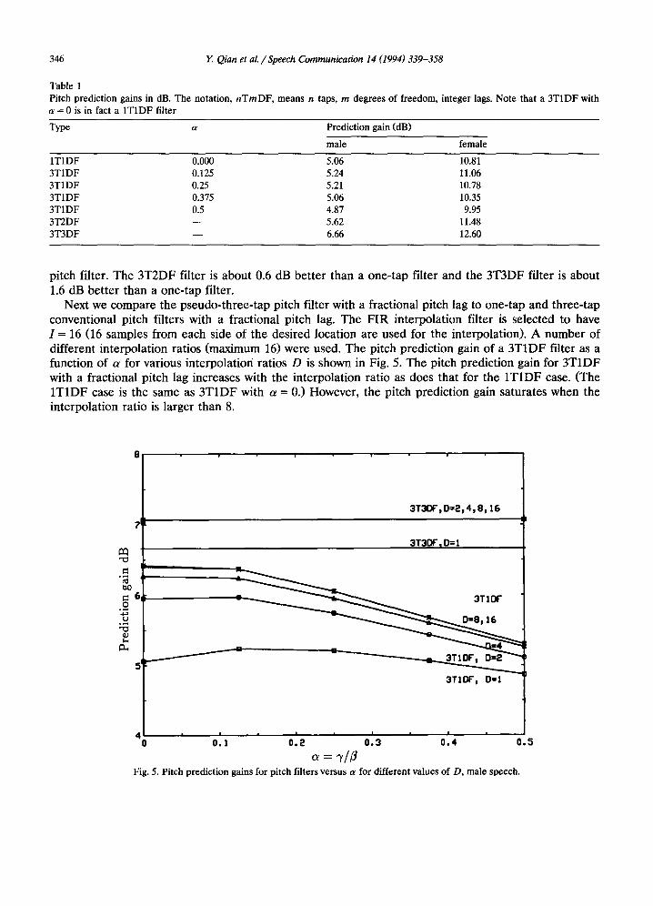
Next we compare the pseudo-three-tap pitch filter with a fractional pitch lag to one-tap and three-tap conventional pitch filters with a fractional pitch lag. The FIR interpolation filter is selected to have I--- 16 (16 samples from each side of the desired location are used for the interpolation). A number of different interpolation ratios (maximum 16) were used. The pitch prediction gain of a 3T1DF filter as a function of a for various interpolation ratios D is shown in Fig. 5. The pitch prediction gain for 3T1DF with a fractional pitch lag increases with the interpolation ratio as does that for the 1T1DF case. (The 1T1DF case is the same as 3T1DF with a = 0.) However, the pitch prediction gain saturates when the interpolation ratio is larger than 8.
3T30F, 0=2~ 4, 8, 16 ?1
3T3OF't D= 1
"0
6 3TIll:"
• I I I
' ° ' o: , ' ' o : 3 ' o . , o . 5 I
0 . 2
Fig. 5. Pitch prediction gains for pitch filters versus a for different values of D, male speech.
Y. Qian et al. / Speech Communication 14 (1994) 339-358 347
14
12
N M
3T L:~'-, FEMALE s CATF'8 I
.9 10
.2 8
3T3OF,MALE~CATM8 w • ,,
3TLM]F,MALE,CATM8 A
ITIDF',MALEjCATM8
e
3T30f', FEMALE, CATF'8
ITIDF,FEMALE,CATF8
4 i I i I i I I
4 8 1 16 In terpola t ion rat io D=1,2,4,8,16
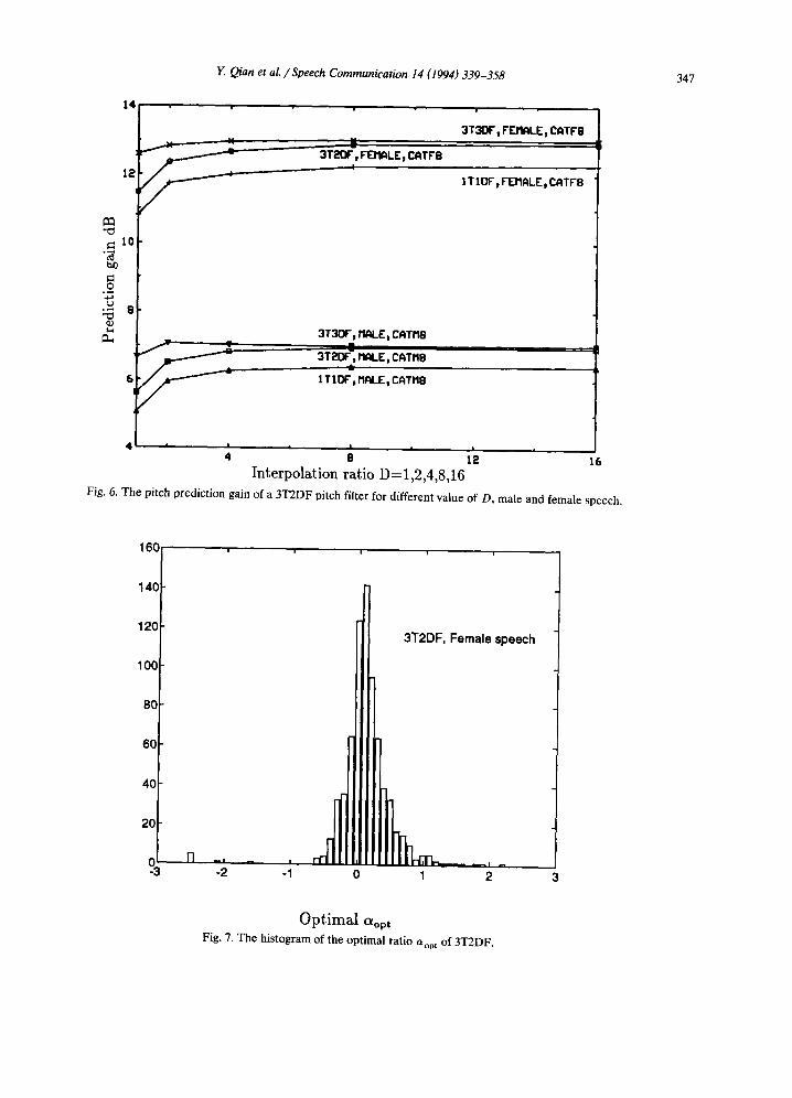
Fig. 6. The pitch prediction gain of a 3T2DF pitch filter for different value of D, male and female speech.
160 ....
140
12(
10(
80
60
40
20
0 -3
3T2DF, Female speech
-2 -1 0 1 2
O p t i m a l aopt Fig. 7. The histogram of the optimal ratio ao, t of 3T2DF.
348 Y. Qian et al. / Speech Communication 14 (1994) 339-358
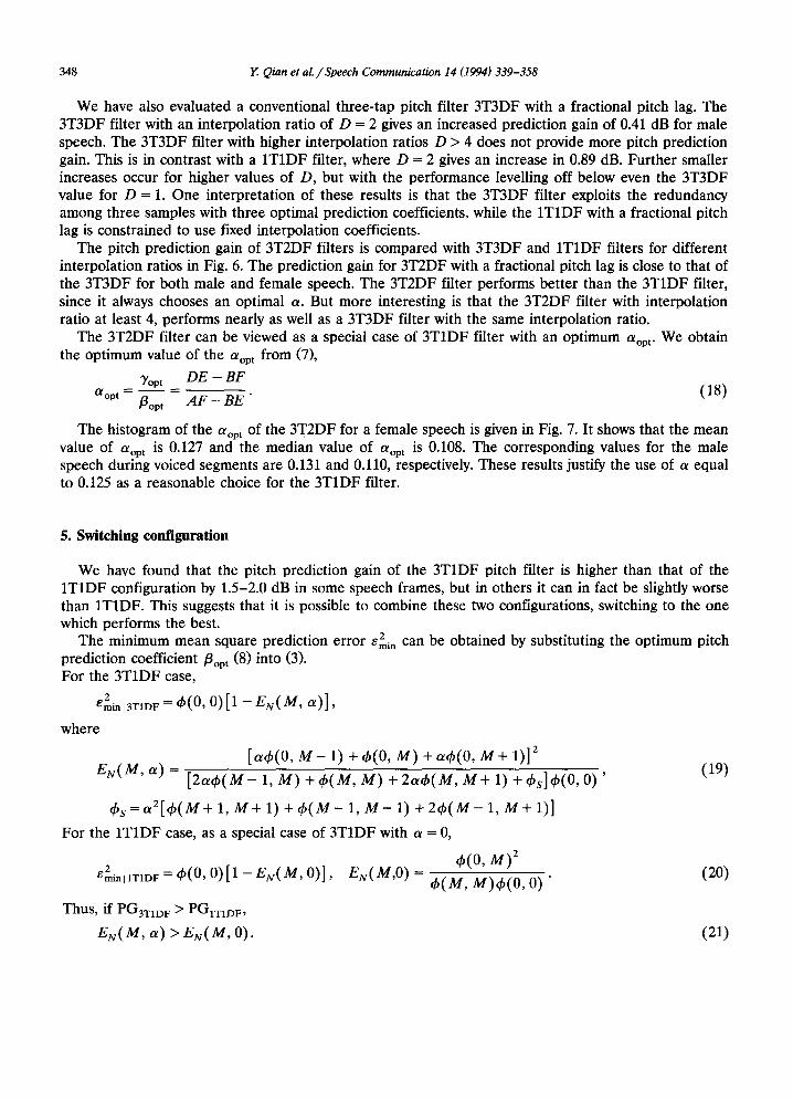
We have also evaluated a conventional three-tap pitch filter 3T3DF with a fractional pitch lag. The 3T3DF filter with an interpolation ratio of D = 2 gives an increased prediction gain of 0.41 dB for male speech. The 3T3DF filter with higher interpolation ratios D > 4 does not provide more pitch prediction gain. This is in contrast with a 1T1DF filter, where D -- 2 gives an increase in 0.89 dB. Further smaller increases occur for higher values of D, but with the performance levelling off below even the 3T3DF value for D = 1. One interpretation of these results is that the 3T3DF filter exploits the redundancy among three samples with three optimal prediction coefficients, while the 1T1DF with a fractional pitch lag is constrained to use fixed interpolation coefficients.
The pitch prediction gain of 3T2DF filters is compared with 3T3DF and 1TIDF filters for different interpolation ratios in Fig. 6. The prediction gain for 3T2DF with a fractional pitch lag is close to that of the 3T3DF for both male and female speech. The 3T2DF filter performs better than the 3TIDF filter, since it always chooses an optimal a. But more interesting is that the 3T2DF filter with interpolation ratio at least 4, performs nearly as well as a 3T3DF filter with the same interpolation ratio.
The 3T2DF filter can be viewed as a special case of 3TIDF filter with an optimum aom. We obtain the optimum value of the Otop t from (7),
]/opt DE - BF O~°pt = f lopt = AF-BE" (18)
The histogram of the aop t of the 3T2DF for a female speech is given in Fig. 7. It shows that the mean value of t~op t is 0.127 and the median value of a o p t is 0.108. The corresponding values for the male speech during voiced segments are 0.131 and 0.110, respectively. These results justify the use of a equal to 0.125 as a reasonable choice for the 3TIDF filter.
5. Switching configuration
We have found that the pitch prediction gain of the 3T1DF pitch filter is higher than that of the 1TIDF configuration by 1.5-2.0 dB in some speech frames, but in others it can in fact be slightly worse than 1TIDF. This suggests that it is possible to combine these two configurations, switching to the one which performs the best.
2 The minimum mean square prediction error emi . can be obtained by substituting the optimum pitch prediction coefficient/30p t (8) into (3). For the 3T1DF case,
E2min[3T1DF = ~ ( 0 , 0 ) [ 1 - EN(M, a)] ,
where
[a¢(0 , M - 1) + ~b(0, M) + a¢(0 , M + 1)] 2
EN(M, a) = [2a~b(M- 1, M) + ¢ ( M , M) + 2a~b(M, M + 1) + ~bs]~b(0, 0 ) ' (19)
~bs=a2[~b(M+ 1, M + 1) + ¢ ( M - 1, M - 1) + 2~b(M- 1, M + 1)]
For the 1T1DF case, as a special case of 3T1DF with a = 0,
2 Emin IITID F "~ ~b(0, 0 ) [ 1 - E N ( M , 0)],
Thus, if PG3TID F > PGtT1DF,
EN(M, a) > EN(M, 0).
b(0, M) 2 E N ( M ' O ) = b(M, M) b(0, 0) " (20)
(21)
Y. Qian et al. / Speech Communication 14 (1994) 339-358 349
~ 0 . 8
o ".~ 0 . 6
o
~0.4 o
~0.2 o
z
[N (M ,A ) o r 3TIOF
EN(M,O) o r ITIDF
o , , , - , - , 33
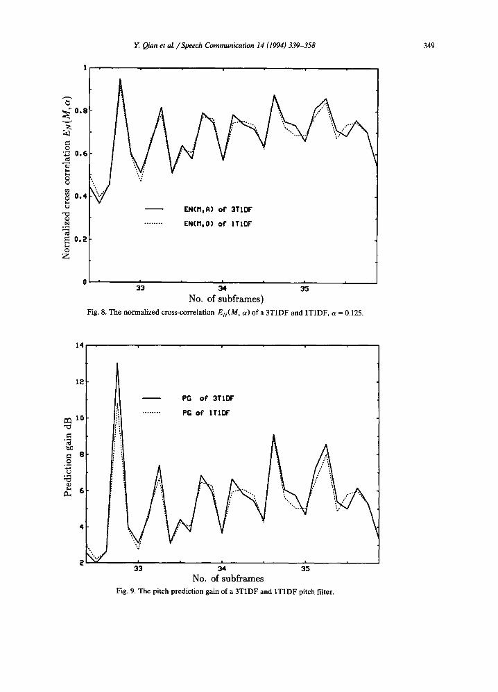
No. of subframes) Fig. 8. The normalized cross-correlation EN(M, a) of a 3T1DF and 1T1DF, a = 0.125.
14
12
,~ 10
~ e
4
i i
PG o f 3TIDF
........ PG o r IT IDF
~ , ~ , ~ ,
No. of subframes Fig. 9. The pitch prediction gain of a 3T1DF and 1T1DF pitch filter.
350 Y. Qian et al. / Speech Communication 14 (1994) 339-358
Table 2 Pitch prediction gains in dB. The two values in the second column indicate that a switches between these values
Type a Prediction gain (dB)
male female
1TIDF 0, 0.0 5.06 10.81 3T1DF 0, 0.125 5.35 11.22 3T1DF 0, 0.25 5.46 11.25 3T1DF 0, 0.375 5.47 11.20 3T1DF 0, 0.5 5.44 11.18
Most segments of a speech signal meet the condition (21). Therefore, the average PG3T1D F is higher than the PG1T1DF, as shown in Table 1. However, there are some subframes which do not conform to the condition. Fig. 8 shows the normalized cross correlation EN(M , a) for a 3T1DF filter and EN(M, 0) for a 1T1DF filter in different subframes. Fig. 9 shows the pitch prediction gain for 3T1DF and 1T1DF filters. EN(M , a) is lower than EN(M, 0) in several subframes. Therefore, the pitch prediction gain PGaTID F of these corresponding subframes is lower than the PG1T1D F.
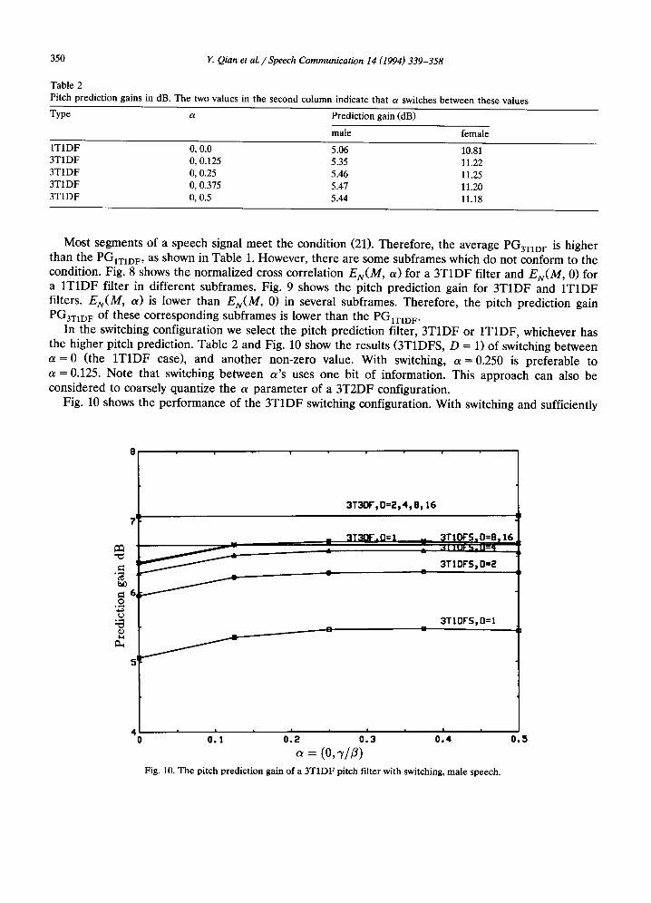
In the switching configuration we select the pitch prediction filter, 3T1DF or 1TIDF, whichever has the higher pitch prediction. Table 2 and Fig. 10 show the results (3TIDFS, D = 1) of switching between a = 0 (the 1TIDF case), and another non-zero value. With switching, a = 0.250 is preferable to a = 0.125. Note that switching between a 's uses one bit of information. This approach can also be considered to coarsely quantize the a parameter of a 3T2DF configuration.
Fig. 10 shows the performance of the 3TIDF switching configuration. With switching and sufficiently
.o
3T30F,D=~,4 ,8 ,16
3T3DF.D=I 3T1OFS:D=8:16
3T1DFS, Dffi2
/
3TIDFS,D=I 0 O
| i !
'0 0:, ' o:2 0' ' .3 0~4 = ( 0 ,
Fig. 10. The pitch prediction gain of a 3TIDF pitch filter with switching, male speech.
0 . 5
Y. Qian et al. / Speech Communication 14 (1994) 339-358 351
high interpolation ratio (more than 4), this configuration outperforms 3T3DF with D = 1. The cost of providing D = 4 for all pitch lags is 2 bits, while the cost of providing the two extra coefficients of a 3T3DF filter is certainly more than 2 bits. We can also compare two other cases, 3T1DF with switching (D = 1) and 1T1DF with D = 2. The cost of providing switching and interpolation are each 1 bit, but the 1T1DF with half sample lag resolution outperforms the switching case with no interpolation. However, as we allocate more bits to compare 3T1DF with switching and D = 2 with 1T1DF (D = 4), the perfor- mance is essentially the same. With another bit allocated (3TIDF with switching, D = 4 and 1T1DF with D = 8), the 3T1DF configuration pulls slightly ahead.
6. Frequency response
The frequency response of the pitch synthesis filter affects the reconstructed speech spectrum in a CELP coder. We compare the frequency response of pseudo-multi-tap synthesis filters 3T2DF and 3T IDF with conventional 1T1DF and 3T3DF filters.
The frequency response of a 3T3DF pitch synthesis filter can be expressed as
1
H(ei° ' ) = 1 - / 3 1 e -j°J(M-1) - /30 e-Jo'M--/3+1 e-Jw(M+l) " (22)
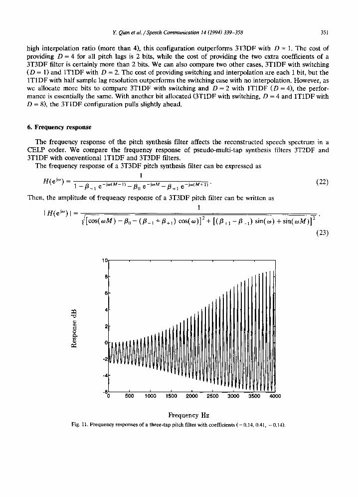
Then, the amplitude of frequency response of a 3T3DF pitch filter can be written as
i n(eJ~,) I = 1 ~ / [ c o s ( o J M ) - / 3 0 - (J -i "[- J +l) COS(O))] 2 + [( /3+1 -- s i n ( w ) + sin(wM)] 2
(23)
o
10
8
6
4
2
0
-2
-4
500 1000 1 5 0 0 2000 2500 3000 3500 4000
Frequency Hz
Fig. 11. Frequency responses of a three- tap pitch filter with coefficients ( - 0.14, 0.41, - 0.14).
352 Y. Qian et al. / Speech Communication 14 (1994) 339-358
o
0
-2
i .
-10
-12
-14
-16
I I I
soo ooo s'oo 2o'oo 2s'oo 3ooo 3soo ooo
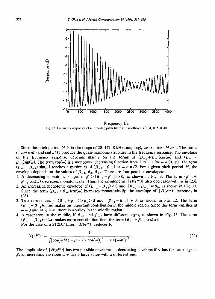
Frequency Hz Fig. 12. Frequency responses of a three-tap pitch filter with coefficients (0.31, 0.25, 0.20).
Since the pitch period M is in the range of 20-147 (8 kHz sampling), we consider M >> 1. The terms of cos(toM) and sin(toM) produce the quasi-harmonic structure in the frequency response. The envelope of the frequency response depends mainly on the terms of (/3_x+/3+l)cos(to) and ( /3÷1- /3_l)sin(to). The term cos(to) is a monotonic decreasing function from 1 to - 1 for to --- (0, ~). The term ( /3÷1- /3-1) sin(to) reaches a maximum of ( /3+1- /3-1) at to = rr/2. For a given pitch period M, the envelope depends on the values of /3_ t,/30,/3 + i. There are four possible envelopes: 1. A decreasing monotonic shape, if /30>(/3_ 1 + / 3 + t ) > 0 , as shown in Fig. 3. The term (/3-1 +
/3+1)cos(to) decreases monotonically. Thus, the envelope of I H(eJ°')l also decreases with to in (23). 2. An increasing monotonic envelope, if (/3_ 1 +/3+1) < 0 and I/3-1 +/3+11 =/30, as shown in Fig. 11.
Since the term (/3-1 +/3+1 )cos(to) increases monotonically, the envelope of I H(eJ'°)l increases in (23).
3. Two resonances, if ( /3_1+/3+1)> /30>0 and I/3÷1-/3_11 >>0, as shown in Fig. 12. The term (/3 +1 - / 3 -1 ) sin(to) makes an important contribution in the middle region. Since this term vanishes at to = 0 and at to = rr, there is a valley in the middle region.
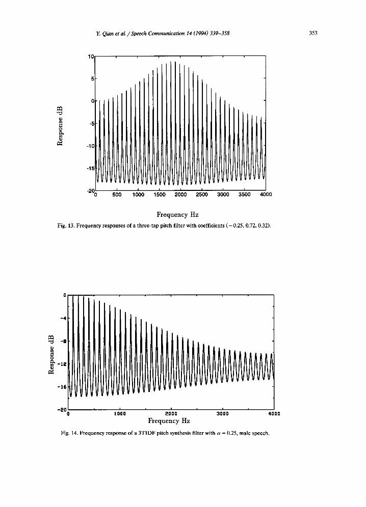
4. A resonance in the middle, if /3-1 and /3+t have different signs, as shown in Fig. 13. The term (/3 +! - / 3 _ 1)sin(to) makes more contribution than the term (/3 +1 -[- / 3 - 1 )cOS(to)" For the case of a 3T2DF filter, I H(ei~')l reduces to
I H ( e i°') [ = (24) /[cos(tou) - / 3 - 2r cos(to)] + [sin(toM)]
The amplitude of I H(ei°')l has two possible envelopes: a decreasing envelope if 3' has the same sign as /3; an increasing envelope if 3' has a large value with a different sign.
Y. Qian et al. / Speech Communication 14 (1994) 339-358 353
o
10
5
C
-5
-1C
-15
-200 ' , 500 1000 1500 2000 4000 2 3 ~ 0 3 ~ 0
Frequency Hz
Fig. 13. Frequency responses of a three-tap pitch filter with coefficients ( -0 .25 , 0.72, 0.32).
0
- 4
- 1 2
- 1 6
- 2 0 0 1000 2000 3000 4000
Frequency Hz
Fig. 14. Frequency response of a 3T1DF pitch synthesis filter with a = 0.25, male speech.
354 Y Qian et al. / Speech Communication 14 (1994) 339-358
For the case of a 3T1DF filter, I H(eJ'°)l becomes
1 I n ( e j°') I = (25)
~/[cos(o~M) - /3(1 + 2a cos(oJ))] 2 + [sin(oJM)] 2
The amplitude of I H(eJ'°)l of a 3T1DF filter has a decreasing envelope for positive a. The frequency response of the 3T1DF filter with a = 0.25 is shown in Fig. 14. This can be compared to Figs. 2 and 3. Let a = 0 in (25). Then, I H(eJ°') I becomes a constant envelope of a 1T1DF pitch filter,
1
I n ( e J ' ) [ = ~ 1 - 2/3 cos(oJM) +/32 (26)
7. Stability
In this section, we discuss the effect of an unstable pitch filter in a CELP coder. There are three procedures to determine the pitch filter parameters, the pitch lag M and the prediction coefficients {/3i}, i = 1, 2, 3: (1) Analyzing the original speech signal by solving a covariance matrix equation, as for a pitch prediction filter in Section 2 and in (Ramachandran and Kabal, 1987); (2) Jointly optimizing the excitation codebook index i, the codebook gain G, the pitch lag M and the {/3 i} by exhaustively searching for the weighted MMSE (minimum mean square error) between the original speech and the perceptually weighted reconstructed signal; (3) Optimizing the M and {/3 i} by sequentially searching for the MMSE or MSPE (modified minimum squared prediction error) (Kleijn et al., 1988).
The third procedure above is often employed in practice and is termed an analysis-by-synthesis search, but can also be viewed as adding a pitch component from an adaptive codebook. For this sequential analysis-by-synthesis search procedure, we assume that the input of the pitch filter is zero. The output of the pitch filter depends on the output of the previous subframe. We find the optimum M and {/3 i} first. Then, we search for the optimum excitation codewords.
There is a local (recursive) pitch synthesis filter in a CELP coder. The transfer function of the pitch synthesis filter can be expressed as
1 H(z) 1 - P ( z ) ' (27)
where
P(z) = 1
E /3i Z-M+i, (28) i = - 1
The input of the pitch synthesis filter, ~(z) is the codeword from the excitation codebook. We can decompose the excitation codeword into two components: an ideal prediction residual (that would be obtained at the analysis stage, shown in Fig. 1) e(z), and a quantization noise output qn(z).
d(z) = e ( z ) +an(z), (29)
where
e (z ) = x ( z ) ( 1 - P ( z ) ) . (30)
The output of the pitch synthesis filter, $(z), is
an(Z) ~(z) 1 - e ( z ) x ( z ) + ( 1 - P ( z ) ) " (31)
Y. Qian et al. / Speech Communication 14 (1994) 339-358 355
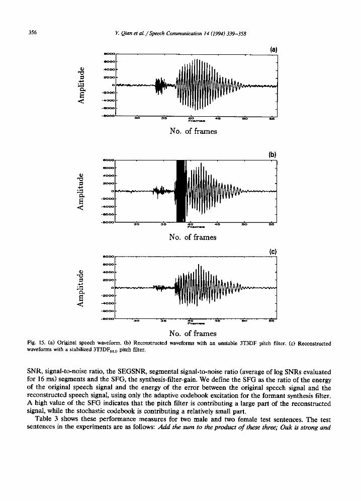
For the first term of (31), the pitch prediction residual, stability is not a problem because of po le /ze ro cancellation in the analysis and synthesis stages. However, the quantization noise passes through only the pitch synthesis filter. If the pitch filter is not stable, this component leads to an increasing pitch filter output. For simplicity, we suppose the quantization noise to be an additive white noise. An unstable filter can result in a large increase of the output noise. In the sequential search procedure, the pitch filter parameters are chosen before the contribution of the stochastic codebook in CELP is considered. The stochastic contribution can drive the output of an unstable pitch filter to large values. This causes distortion of the reconstructed signal. The enhanced quantization noise can be further augmented in the following subframes, because the adaptive codebook is updated with the accumulated noise of an unstable pitch filter. The average SNR of a CELP coder for an adaptive codebook procedure with a conventional (unquantized pitch coefficient) 3T3DF pitch filter for one test sentence can fall to 3.89 dB, comparing to 9.0 dB for a 1T1DF filter. The waveform of the reconstructed speech with an adaptive codebook for a 3T3DF in several subframes of an unstable pitch filter is compared with the original speech signal (Fig. 15(a)) and is shown in Fig. 15(b). Fig. 15(c) gives the reconstructed waveform with a stabilized pitch filter 3T3DFbL 0 under a simple sufficient stable condition, as described in the sequel.
A simplified stability test and four stabilization techniques have been proposed to efficiently tame an unstable pitch filter in (Ramachandran and Kabal, 1987). The simple sufficient stability conditions are
I/31 < 1, 1TIDF,
I/3_1[+1/301+1/3+11 < 1 , 3T3DF. (32)
Let a =/3 _ 1 + /3 + 1 and b =/3 _ ~ - /3 + r The sufficient stability conditions for a 3T3DF pitch filter are (Ramachandran and Kabal, 1987)
(1) if l a l ~ > l b l , [/3_1[ + [/30 [ + [/3+1[ < 1. (33)
(2) if [al < Ibl and 1/30L+lal < 1 ; b2<~a or b 2 / 3 2 - ( 1 - b 2 ) ( b e - a 2 ) < O .
The tight sufficient conditions reduce to the simple sufficient conditions (32) for both 3T1DF and 3T2DF filters, since b = 0 and l a [ > 0. The 3T1DF pitch filter has a better stability performance than a conventional 3T3DF filter, since we constrain the side prediction coefficients /3_ 1 = /3 +1 t o be a small proportion of the center coefficient/30. It is easier for the 3T1DF filter to meet the sufficient condition for the simplest stability test in (32),
1 I/3ol < l + 2 l a l " (34)
For a 3T2DF pitch filter with/3_ 1 = /3 + 1 = 3'' the simplest sufficient condition is
213'1+1/301 < 1 .
Since each of 1 3' I and [/301 is possibly larger than 1, the chance that the filter violates the sufficient condition is higher than that for a 3T1DF filter.
A simple stabilization method by scaling the coefficients is used to stabilize the pitch synthesis filter. We scale down the pitch coefficients by multiplying a factor c,
l/th c = (I/3-11+1/301+1/3+11)' if(l/3-1l+l/3°l+l/3+ll)>Vth" (35)
The threshold Vtn is an experimentally determined threshold. With Vth = 0% no stabilization is used. With Vth = 1, a strict stability condition is imposed.
The pseudo-multi-tap pitch filters, 3T1DF and 3T2DF pitch filters were incorporated into an FS1016 4.8 kbi t / s CELP coder (Campbell et al., 1990). We employ three performance measures: the average
356 Y. Qian et aL / Speech Communication 14 (1994) 339-358
° , - q
.<
(a)
600O
4000
2OOO
- 200
- 400<1
- eO00
*eO00 i i : i i i 3O ~5 4O 45 643 56
Fr ln lem
No. of frames
~D
. ¢ , . q
<
8 O 0 O
- 2 O 0 O
- - 4 0 0 0
- 6 0 0 0
- 8 O 0 0
(b)
30 35 40 45 SO SS F ra r r t~e
No. of frames
<
aooo
eooo ::: - 4 0 ~
(c)
3O 35 4O 45 5O 65 Frames
No. of frames Fig. 15. (a) Original speech waveform. (b) Reconstructed waveforms with an unstable 3T3DF pitch filter. (c) Reconstructed waveforms with a stabilized 3T3DFbl.0 pitch filter.
SNR, signal-to-noise ratio, the SEGSNR, segmental signal-to-noise ratio (average of log SNRs evaluated for 16 ms) segments and the SFG, the synthesis-filter-gain. We define the SFG as the ratio of the energy of the original speech signal and the energy of the error between the original speech signal and the reconstructed speech signal, using only the adaptive codebook excitation for the formant synthesis filter. A high value of the SFG indicates that the pitch filter is contributing a large part of the reconstructed signal, while the stochastic codebook is contributing a relatively small part.
Table 3 shows these performance measures for two male and two female test sentences. The test sentences in the experiments are as follows: Add the sum to the product of these three; Oak is strong and
Y. Qian et al. / Speech Communication 14 (1994) 339-358 357
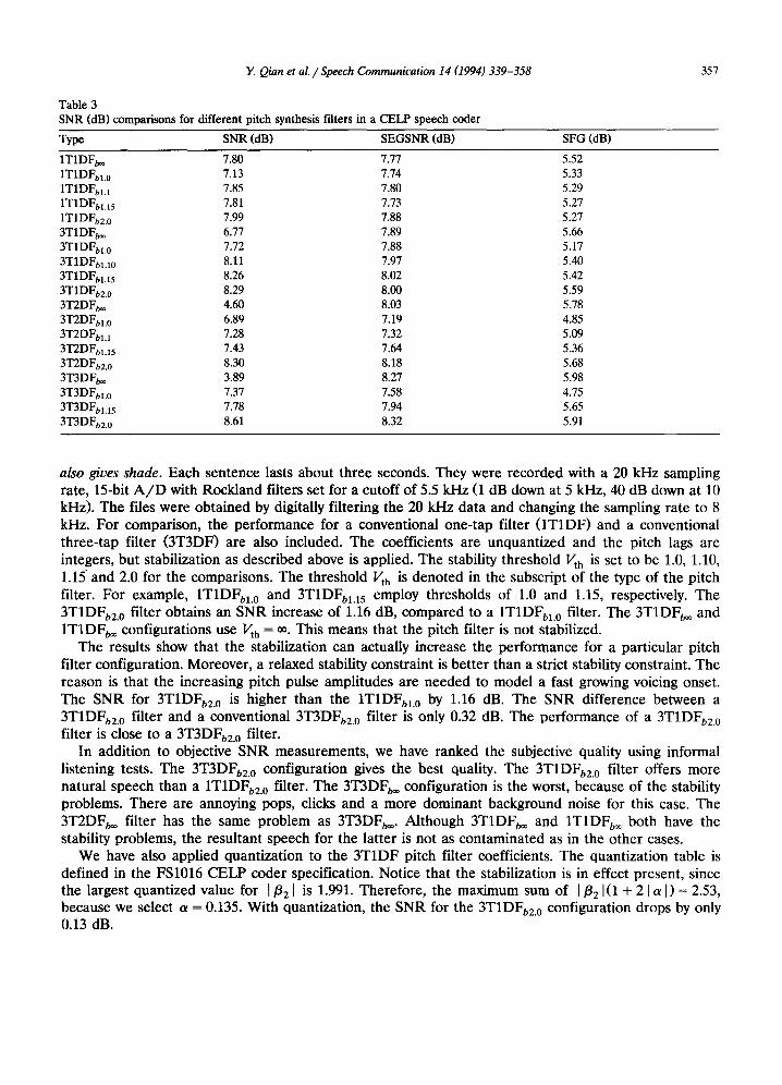
Table 3 SNR (dB) comparisons for different pitch synthesis filters in a CELP speech coder
Type SNR (dB) SEGSNR (dB) SFG (dB)
1T1DFb~ 7.80 7.77 5.52 1T1DFbl.0 7.13 7.74 5.33 1T1DFbH 7.85 7.80 5.29 1T1DFbH 5 7.81 7.73 5.27 1T1DFb2.0 7.99 7.88 5.27 3T1DFb~ 6.77 7.89 5.66 3T1DFbl.0 7.72 7.88 5.17 3T1DFblA0 8.11 7.97 5.40 3T1DFbl.I 5 8.26 8.02 5.42 3T1DFb2.0 8.29 8.00 5.59 3T2DFb~ 4.60 8.03 5.78 3T2DFbL 0 6.89 7.19 4.85 3T2DFbH 7.28 7.32 5.09 3T2DFt, I.15 7.43 7.64 5.36 3T2DFb2.0 8.30 8.18 5.68 3T3DFt~ 3.89 8.27 5.98 3T3DFbL 0 7.37 7.58 4.75 3T3DFbL15 7.78 7.94 5.65 3T3DFb2.0 8.61 8.32 5.91
also gives shade. Each sentence lasts about three seconds. They were recorded with a 20 kHz sampling rate, 15-bit A / D with Rockland filters set for a cutoff of 5.5 kHz (1 dB down at 5 kHz, 40 dB down at 10 kHz). The files were obtained by digitally filtering the 20 kHz data and changing the sampling rate to 8 kHz. For comparison, the performance for a conventional one-tap filter (1T1DF) and a conventional three-tap filter (3T3DF) are also included. The coefficients are unquantized and the pitch lags are integers, but stabilization as described above is applied. The stability threshold Vth is set to be 1.0, 1.10, 1.15 and 2.0 for the comparisons. The threshold Vth is denoted in the subscript of the type of the pitch filter. For example, 1T1DFbl.0 and 3T1DFbl.15 employ thresholds of 1.0 and 1.15, respectively. The 3T1DFb2.0 filter obtains an SNR increase of 1.16 dB, compared to a 1T1DFbl.0 filter. The 3T1DFb~ and 1T1DFb~ configurations use Vth = ~. This means that the pitch filter is not stabilized.
The results show that the stabilization can actually increase the performance for a particular pitch filter configuration. Moreover, a relaxed stability constraint is better than a strict stability constraint. The reason is that the increasing pitch pulse amplitudes are needed to model a fast growing voicing onset. The SNR for 3T1DFb2.0 is higher than the 1T1DFbl.0 by 1.16 dB. The SNR difference between a 3T1DFb2.0 filter and a conventional 3T3DFbg.0 filter is only 0.32 dB. The performance of a 3T1DFb2.0 filter is close to a 3T3DFbz.0 filter.
In addition to objective SNR measurements, we have ranked the subjective quality using informal listening tests. The 3T3DFb2.O configuration gives the best quality. The 3T1DFb2.0 filter offers more natural speech than a 1T1DFb2.0 filter. The 3T3DFb~ configuration is the worst, because of the stability problems. There are annoying pops, dicks and a more dominant background noise for this case. The 3T2DFb~ filter has the same problem as 3T3DFb~. Although 3T1DFb~ and 1T1DFb~ both have the stability problems, the resultant speech for the latter is not as contaminated as in the other cases.
We have also applied quantization to the 3T1DF pitch filter coefficients. The quantization table is defined in the FS1016 CELP coder specification. Notice that the stabilization is in effect present, since the largest quantized value for I/321 is 1.991. Therefore, the maximum sum of I/32 I(1 + 2 1 a I) = 2.53, because we select a = 0.135. With quantization, the SNR for the 3T1DFb2.0 configuration drops by only 0.13 dB.
358 Y. Qian et al. / Speech Communication 14 (1994) 339-358
Finally, we have evaluated the SNR and SEGSNR for a 3T1DF pitch filter with fractional pitch lags and pitch quantizer, defined in the FS1016 CELP coder. Note that these fractional pitch lags are not uniformly spaced - small lags have higher resolution than large lags. The results show that the SNR and SEGSNR are higher than that of the standard FS1016 coder by 0.45 dB and 0.1 dB. An informal listening test shows that the improved CELP coder with 3T1DF pitch filter is slightly better than the original FS1016 CELP coder.
8. Summary and discussion
We have presented and analyzed two pseudo-multi-tap pitch prediction filter configurations, 3T2DF and 3T1DF. The pseudo-multi-tap pitch filters can be viewed as a shape/ga in decomposition, with the 3T1DF filter having only one shape and the switching 3T1DF filter having two shapes. This then reduces the multi-tap coding problem to a scalar quantization of the gain value. The prediction gain of pseudo-three-tap pitch prediction filter is higher than that of a one-tap pitch prediction filter. The frequency response is more desirable than a conventional one-tap and three-tap pitch synthesis filter because of the symmetrical and small side prediction coefficients. The pseudo-multi-tap pitch filter can also be used in the synthesis stage of a speech coder, with the optimal lag and coefficients determined using an analysis-by-synthesis approach. Stabilization, using a relaxed stability criterion, is applied by scaling the pitch filter coefficients. Coefficient scaling based on a relaxed sufficient constraint allows for weakly unstable pitch synthesis filters, which can track fast changing segments during an unvoiced to voiced onset. The pseudo-multi-tap pitch filter has fewer degrees of freedom than a traditional three-tap pitch filter, that is, fewer parameters need to be coded for transmission in a speech coding context. The performance of a US federal standard FS1016 4.8 kbi t / s CELP coder with a pseudo-multi-tap pitch filter is bet ter than that with a conventional one-tap pitch filter.
References
J.P. Campbell, T.E. Tremain and V.C. Welch (1990), "The proposed federal standard 1016 4800 bps voice coder: CELP", Speech Technology, pp. 58-64.
R. Crochiere and L. Rabiner (1983), Multirate Digital Signal Processing, Prentice Hall, Englewood Cliffs, NJ. V. Iyengar and P. Kabal (1991), "A low delay 16 kbits/s speech coder", IEEE Trans. Signal Process., Vol. 39, pp. 1049-1057. W.B. Kleijn, D.J. Krasinski and R.H. Ketchum (1988), "Improved speech quality and efficient vector quantization in SELP", Proc.
IEEE lnternat. Conf. Acoust. Speech Signal Process., New York, N~, 11-14 April 1988, pp. 155-158. P. Kroon and B.S. Atal (1991), "Pitch predictors with high temporal resolution", IEEE Trans. Signal Process., Vol. 39, pp. 733-735. R. Ramachandran and P. Kabal (1987), "Stability and performance analysis of pitch filters in speech coders", IEEE Trans. Acoust.
Speech Signal Process., Vol. 35, pp. 937-946. R. Ramachandran and P. Kabal (1989), "Pitch prediction filters in speech coding", IEEE Trans. Acoust. Speech Signal Process.,
Vol. 37, pp. 467-478. M. Schroeder and B. Atai (1985), "Code-excited linear prediction (CELP): High quality speech at very low bit rates", Proc. IEEE
Internat. Conf. Acoust. Speech Signal Process., Tampa, FL, 26-29 March 1985, pp. 937-940.