Embed Size (px)
Citation preview

8th International Conference on the Application of Stress-Wave Theory to Piles, Lisbon, 2008
Pile foundation testing of a hurricane resistant jetty.
Middendorp, P. Profound BV, The Netherlands
Plooy, P.J. Lievense Consulting Engineers, The Netherlands
Kruit,D.B. Volker Stevin Construction Europe BV, The Netherlands
Keywords: pile testing, PDA, DLT, STN, PDPWAVE, DLTWAVE, Pile Driving Analysis, Statnamic, hurricane, jetty, calcareous soils
ABSTRACT: To prevent pile driving problems during the construction of a jetty at Grenada a proof testingapproach was applied whereby test pile driving was performed at several places where the jetty was to beconstructed. With these proof testing results the design could be finalised and pile driving criteria could beestablished for the construction phase of the jetty. This resulted in very efficient pile driving during construction. A half year after construction the jetty was able to withstand the onslaught by Ivan (2004), aCategory 5 hurricane.
1 INTRODUCTION
In 2004, the company Zublin Grenada Ltd. contracted with Lievense Consulting Engineers from the Netherlands to design a cruise terminal for the Caribbean Island Grenada as part of a private development project. The development of this terminal included land reclamation, rock armoured sea defense, tender jetty and main jetty. The jetty can accommodate up to 4 cruise ships, including the latest generation of cruise vessels which are over 300 m in length. The jetty was constructed by the Dutch contractor Volker Stevin Construction Europe BV (2004) under the supervision of Posford Haskoning from the UK. Contractor and designer worked closely together with respect to working methods, design and cost management.
Grenada is in the southern part of the hurricane
alley in the Caribbean Sea, so the design had to take into account that waves with heights of 9m could hit the jetty. As a result, the requirements for the foundation were demanding, as it had to be able to withstand not only the loads generated by these high waves, but also those generated by the cruise ships. This was further complicated by the subsoil in the area: coral sands and large cavities. With the design calling for driven steel pipe piles, there was obviously a considerable risk for early refusal if closed ended piles were to be used (which would
Drive-ability study
Wave Equation Program (PDPWAVE)
Monitoring (PDA)
Determination of pile toe level.
TNO Method, Case Method
Re-drives (DLT):
Signal matching (DLTWAVE),
Estimate shaft and toe resistance
Statnamic Load Testing (STN)
(Checking PDA and DLT results)
Load displacement behaviour
Pile Driving Protocol
Working Piles
Impact Energy Registration (IHC)
Blow count monitoring
Pile Design
Soil Investigation
1
2
3
4
5
6
7
8
Figure 1. Proof Testing Approach

8th International Conference on the Application of Stress-Wave Theory to Piles, Lisbon, 2008
limit the tension resistance), while if open ended piles were to be used the toe (compression) resistance could be too low. Because of these uncertainties and the limited information derived from the soil investigation, a proof testing approach was applied. (Fig 1).
2 PROOF TESTING
The international literature offers a range of design methods and correlations for calcareous soils. However, the interpretation of these methods is rather subjective, and the uncertainty in the predicted pile capacity is considerable. It was therefore advised to do extensive in-situ pile testing.
For the Grenada project the pertinent questions were:
- what steel pile lengths are to be imported from Europe?
- do we need closed pile tips, or are open-ended piles more economical?
- if we use closed piles, can sufficient penetration be guaranteed for tension resistance?
- can a driving protocol be developed that will guarantee sufficient resistance, based on the blow count of each pile during driving?
To answer these questions a pile testing program
was performed on a number of test piles (see Table 1).
This program included the following:
- Drive-ability studies (PDP) with the wave equation program PDPWAVE
- Monitoring during pile driving (PDA) - Redrives (DLT) with signal matching
(DLTWAVE) - Statnamic Load Testing (STN) to
confirm capacities in compression - Static pull out tests, to confirm shaft
friction The pile testing was performed by Profound in
close cooperation with the designer and the contractor in 2002 and 2003 to determine how sufficient shaft friction and toe resistances could be obtained, while maintaining pile driving efficiency. Different configurations of open ended, partly closed and closed ended pile toes were tested at different locations (Fig. 2). Based on these results the appropriate pile length and pile toe were determined for each pile location along the jetty depending on the actual soil condition at each location. Moreover pile driving criteria were established for the construction phase of the jetty. This resulted in very efficient pile driving during construction without any unforeseen problems.
3 PILE DATA
The test piles with a diameter of 0.914 m, a wall thickness of 17.2 mm and steel grade X65, varied in
Pile/ Location/ Number
Pile Toe
Type
Pile Length
Toe Depth
Testing Type
No m MSL m 1 DMC+ 42,00 -24.00 PDA,DLT -25.25 PDA,DLT
2 Open 37,25 -25.75 PDA,DLT A Open 36.50 -33.50 PDA
A1 Open 33.50 -33.25 Vibrating in and out
C Open 36.50 -33.50 PDA +12.25 -45.75 PDA +12.25 -48.25 PDA,DLT -49.00 PDA,DLT -55.00 PDA, DLT
STN C1 Closed 49.50 -43.00 PDA,DLT,
STN, pull out test
E Open 36.50 -22.50 PDA, vibration in
& out
Table 1. Pile testing program
Figure 2. Test locations

8th International Conference on the Application of Stress-Wave Theory to Piles, Lisbon, 2008
length between 36.5 m and 61 m. The piles were first stabbed by a vibratory hammer and further
driven with a IHC S90 hydraulic hammer. The various pile toe configurations were:
1. Open ended 2. DMC+ :
plates in H-shape welded inside pile tip 3. Closed :
closure plate with stiffeners and 6 holes of 12 cm cut out
4 SOIL DATA
The geology of Grenada is part of the Lesser Antilles, a chain of islands in the eastern part of the
Caribbean Sea. Grenada is the southernmost island of the inner arc and was formed in the early Tertiary Period. The field investigation comprised the advancement of ten boreholes in the sea. SPT was performed using a manual hammer raised by a rope pull.
This offered a qualitative description of the
subsoil, and a quantitative indication of the resistance. Based on these data a soil profile along the jetty was developed focusing on locating the highest soil layer with adequate bearing capacity (N > 100).
The borehole results indicated scattered layers of
loose to dense coral sands with N-values varying between 0 and 88 but also showed areas with cavities.
5 PILE DRIVING ANALYSIS (PDA)
Strain and acceleration measurements were carried out with instruments mounted sufficiently far below the driving head to ensure that representative signals could be obtained and that the risk of any damage to the transducers during stabbing/driving was minimal. The transducers were installed in two sets diametrically opposite to each other to eliminate the effects of bending stresses and to provide
Figure 4. Closed ended pile toe
Figure 5. Example PDA results, with blow counts. driving resistance, max. compression and transferred energy.
Figure 3. DMC+, partly closed ended pile toe
8th International Conference on the Application of Stress-Wave Theory to Piles, Lisbon, 2008
redundancy. The strain transducers were calibrated for a measuring range of 0 to 1,500 μm/m. The accelerometers were of a piezo-resistive type. These accelerometers are one order of magnitude more accurate than the more common piezo-electric accelerometers, because they have hardly any zero shift. The accelerometers were calibrated for a measuring range of 0 to 6,000 g. High quality measurements like steel on steel pile driving such as with the Hydraulic IHC hammers requires a high sampling rate of 50 kHz to allow full digital recording of the signals. The signals were stored in a non compressed digital format, using the Foundation Pile Diagnostic Systems (FPDS-7) from Profound as data acquisition system (2008).
6 REDRIVES (DLT)
Redrives were performed after a set-up period varying from 1 day till 1 week. The results were analyzed with the signal matching program DLTWAVE.
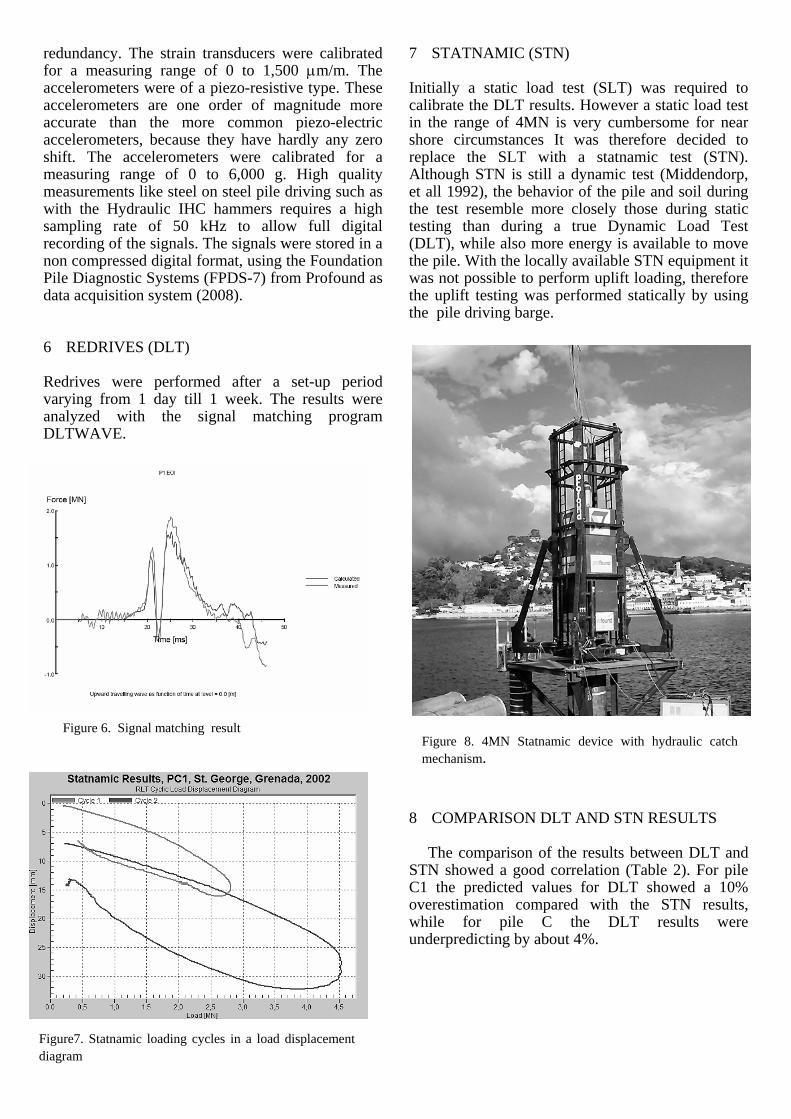
7 STATNAMIC (STN)
Initially a static load test (SLT) was required to calibrate the DLT results. However a static load test in the range of 4MN is very cumbersome for near shore circumstances It was therefore decided to replace the SLT with a statnamic test (STN). Although STN is still a dynamic test (Middendorp, et all 1992), the behavior of the pile and soil during the test resemble more closely those during static testing than during a true Dynamic Load Test (DLT), while also more energy is available to move the pile. With the locally available STN equipment it was not possible to perform uplift loading, therefore the uplift testing was performed statically by using the pile driving barge.
8 COMPARISON DLT AND STN RESULTS
The comparison of the results between DLT and STN showed a good correlation (Table 2). For pile C1 the predicted values for DLT showed a 10% overestimation compared with the STN results, while for pile C the DLT results were underpredicting by about 4%.
Figure 8. 4MN Statnamic device with hydraulic catch mechanism.
Figure 6. Signal matching result
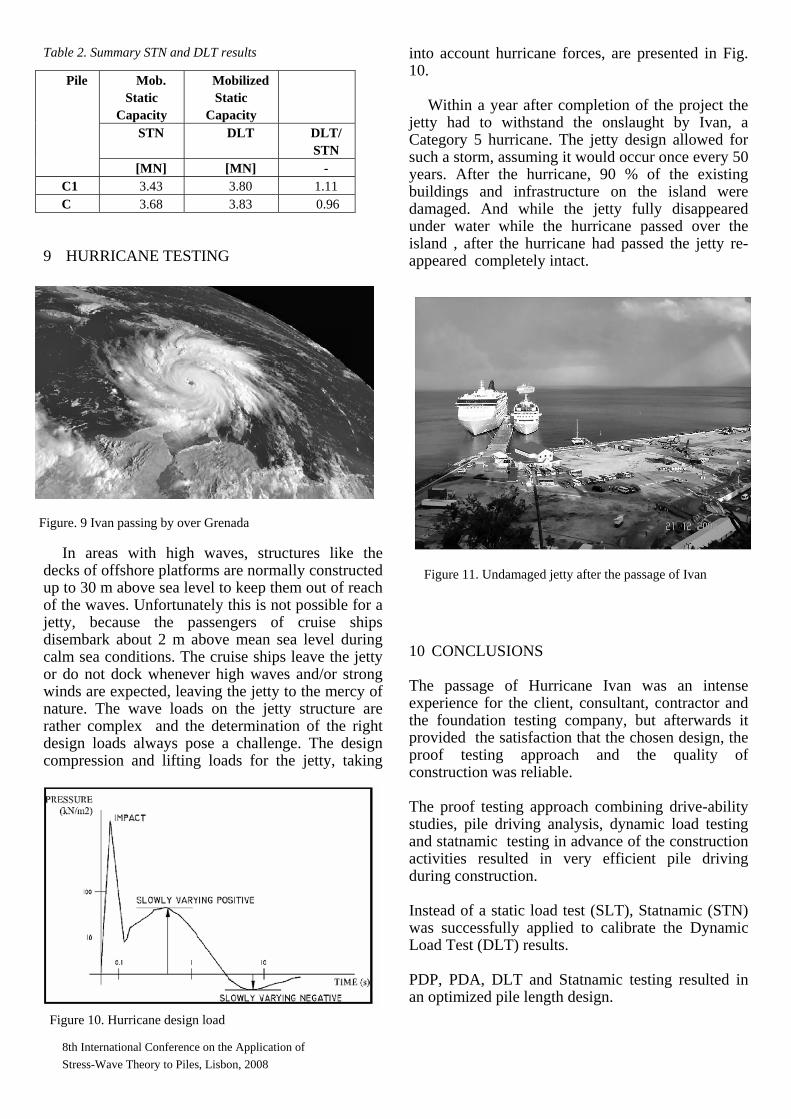
Figure7. Statnamic loading cycles in a load displacement diagram
8th International Conference on the Application of Stress-Wave Theory to Piles, Lisbon, 2008
Table 2. Summary STN and DLT results
Mob. Static
Capacity
Mobilized Static
Capacity
STN DLT DLT/ STN
Pile
[MN] [MN] - C1 3.43 3.80 1.11 C 3.68 3.83 0.96
9 HURRICANE TESTING
In areas with high waves, structures like the decks of offshore platforms are normally constructed up to 30 m above sea level to keep them out of reach of the waves. Unfortunately this is not possible for a jetty, because the passengers of cruise ships disembark about 2 m above mean sea level during calm sea conditions. The cruise ships leave the jetty or do not dock whenever high waves and/or strong winds are expected, leaving the jetty to the mercy of nature. The wave loads on the jetty structure are rather complex and the determination of the right design loads always pose a challenge. The design compression and lifting loads for the jetty, taking
into account hurricane forces, are presented in Fig. 10.
Within a year after completion of the project the
jetty had to withstand the onslaught by Ivan, a Category 5 hurricane. The jetty design allowed for such a storm, assuming it would occur once every 50 years. After the hurricane, 90 % of the existing buildings and infrastructure on the island were damaged. And while the jetty fully disappeared under water while the hurricane passed over the island , after the hurricane had passed the jetty re-appeared completely intact.
10 CONCLUSIONS
The passage of Hurricane Ivan was an intense experience for the client, consultant, contractor and the foundation testing company, but afterwards it provided the satisfaction that the chosen design, the proof testing approach and the quality of construction was reliable. The proof testing approach combining drive-ability studies, pile driving analysis, dynamic load testing and statnamic testing in advance of the construction activities resulted in very efficient pile driving during construction. Instead of a static load test (SLT), Statnamic (STN) was successfully applied to calibrate the Dynamic Load Test (DLT) results. PDP, PDA, DLT and Statnamic testing resulted in an optimized pile length design. Figure 10. Hurricane design load
Figure. 9 Ivan passing by over Grenada
Figure 11. Undamaged jetty after the passage of Ivan

8th International Conference on the Application of Stress-Wave Theory to Piles, Lisbon, 2008
Correlating the different test results with each other and with the blow count records resulted in a practical driving protocol and in acceptance criteria.
11 REFERENCES
Middendorp, P. Bermingham, B Kuiper, Statnamic load testing of foundation piles. 4th International Conference on Stress Waves, The Hague, Balkema, 1992. Volker Stevin Construction Europe, Grenada Cruise Terminal Construction of Marine Fascilities. Document no. W2764-QA-101.05-03, 2004
Profound - Specifications for PDA and DLT Foundation Pile Diagnostic Systems FPDS, document PDA03700-05-2008-PDA-DLT, 2008


![Pile Foundation Design[1] - ITDmtp.itd.co.th/ITD-CP/data/PileFoundationDesign.pdf · Introduction to pile foundations Pile foundation design Load on piles Single pile design Pile](https://img.pdfslide.net/doc/110x75/5a6ffb387f8b9ab1538b8376/pile-foundation-design1-itdmtpitdcothitd-cpdatapilefoundationdesignpdfpdf.jpg)