Embed Size (px)
Citation preview
25th International Conference on Ground Control in Mining
354
ABSTRACT
A survey of pillar conditions was carried out at 21 operating limestone mines that use the room-and-pillar method. The surveyed pillars were all located in rock that was classified as “Good” to “Very Good” using the RMR rock mass classification system. The average pillar width was 14.5m and the width to height ratio varied between 0.53 and 3.52. Pillar conditions were rated using a visual rating system that accounts for the effect of geological structures as well as stress related fracturing. Nine cases of pillar instability were recorded. Pillar instabilities were typically limited to individual pillars or small groups of pillars within an otherwise stable layout. Local geological structures such as inclined discontinuities or weak bedding planes contributed to instability in seven of nine cases that were observed. Elevated pillar stresses contributed to instability in the two remaining cases. All the unstable pillars observed had width-to-height ratios of less than 1.5. It is concluded that pillar instability is most likely to be caused by unfavorable geological structures in pillars with width to height ratios of less than 1.5. Stress related instability such as rib spalling becomes more prevalent when the average pillar stress approaches approximately 20 MPa.
INTRODUCTION Underground limestone mines in the United States make use of variations of the room-and-pillar method to extract limestone formations that are generally flat lying, but may dip up to 35°. Pillar stability is one of the requisites for safe working conditions in a room-and-pillar mine. Unstable pillars can result in rock falls from the pillar ribs and can lead to the collapse of the roof if one or more pillars should fail. Fall of ground accidents were the cause of 36% of fatalities and 12% of all injury related lost work days in underground limestone mines in the decade of 1996 to 2005 (Mine Safety and Health Administration, 2006). Current research at the National Institute for Occupational Safety and Health (NIOSH) has the objective to reduce ground fall accidents in limestone mines through safe pillar and roof span design. As part of this research a survey of pillar stability in limestone mines was conducted in the Eastern United States. The
rock mass properties, mining dimensions, pillar performance and roof conditions were recorded at each site. This paper summarizes the data collected, describes examples of pillar instability and presents a discussion of the likely causes of instability.
FIELD SURVEY OF PILLAR PERFORMANCE
Mining Areas and Geological Setting Data collection visits were made to 21 different underground stone mine sites in the Central and Eastern United States. The data were collected at mine sites and grouped in the following four limestone mining areas:
a. Northern Appalachian Area: The Northern Appalachian limestone mining area includes Pennsylvania and Northern West Virginia. Three limestone deposits found in this area were examined, locally known as the Loyalhanna, Greenbrier, and Vanport limestone. The oldest is the Loyalhanna limestone. It is of Mississippian age and is generally flat-lying, cross bedded, and very silaceous (Adams, 1970). The Greenbrier limestone is an extensive unit deposited during the Mid-Mississippian and occurs above the Loyalhanna. The uppermost limestone in this area is the Vanport limestone. The Vanport limestone is a member of the Allegheny group of Pennsylvanian age and is generally flat-lying (Iannacchione and Coyle, 2002).
b. Southern Appalachian Area: The Southern Appalachian limestone mining area consists of Southern West Virginia, Western Virginia, Eastern Tennessee, and Eastern Kentucky. Economic horizons include limestone within the Chickamauga Group and the Monteagle limestone formation. The steeper dipping Orodovician Chickamauga Group is mined at dips of up to 35 degrees. The Monteagle is a gently dipping Upper Mississippian limestone which is mined on more than one horizon, (Brann and Freas, 2003).
c. Cincinnati Arch Area: The Cincinnati Arch limestone mining area is essentially associated with an anticlinal (upward or high in the center) fold that brings Ordovician limestones and dolomites near the surface, (Hansen, 1977). The axis of the Cincinnati Arch extends southward from Ohio, east of Cincinnati to Tennessee. The limestone formations are gently dipping. Economic horizons include the Camp Nelson and the Tyrone.
PILLAR STABILITY ISSUES BASED ON A SURVEY OF PILLAR
PERFORMANCE IN UNDERGROUND LIMESTONE MINES
Gabriel S. Esterhuizen, Sr. Research Fellow Anthony T. Iannacchione, Acting Geotechnical Engineering Section Chief
John L. Ellenberger, Research Geophysicist Dennis R. Dolinar, Mining Engineer
NIOSH-Pittsburgh Research Laboratory Pittsburgh, PA, USA

25th International Conference on Ground Control in Mining
355
d. Illinois Basin Area: The Illinois Basin limestone mining area extends from western Indiana to Illinois and south to Kentucky. The area primarily contains Silurian to Mississippian sediments. Dolomite and limestones are the dominant lithology, followed by shale, sandstone, chert, anhydrite, and coal. Economic horizons are located in the Galena-Platteville group. The formations are relatively flat lying and undisturbed. High quality limestone is produced from crystalline reef formations, (Swann, 2006; U.S. Geological Survey, 2006).
Data Collected Data were collected on rock strength, jointing and other geological structures, pillar dimensions, pillar performance and roof stability. Between two and five data sets were collected at each mine site. A data set attempts to describe the general performance of the pillar layout at each location by inspecting an area of approximately 100 by 100 m (300 x 300 ft). It was found that individual unstable pillars can occur within an otherwise stable layout. In such cases, the unstable pillars were recorded separately and the likely causes of instability noted. The following data were collected:
1. Rock mass data, including rock strength, joint frequency, joint conditions and groundwater condition. The data was collected in accordance with the requirements of the RMR system of rock mass classification (Bieniawski, 1989). Since drill core was not available at any of the sites, the rock quality designation (RQD) could not be obtained. The joint frequency approach, proposed by Laubscher (1990), was used to obtain the combined joint spacing and RQD rating. The joint frequency was measured in two orthogonal windows, each 3 m wide by 1.8 m high. Rock strength was based on field estimates, supplemented by uniaxial compressive strength (UCS) test data. The presence of continuous geological structures in each area was observed and their orientations and spacing recorded. Continuous structures were defined as any structure that exceeded 10m in dip or strike continuity. These types of structures typically extended from the roof to the floor of a pillar or extended across the width of a room.
2. Pillar conditions were assessed using a visual rating system
broadly based on similar classification systems developed by Lane et al. (1999), Siefert et al. (2003), Krauland and Soder (1987), Lunder (1994) and Pritchard and Hedley (1993). The ratings were divided into two categories; the first is the Pillar Stress Rating, which describes the effects of stress related fracture through intact rock, shown in table 1. The second is the Geological Structure Rating, which describes geological effects on the pillar shape, such as joint defined block release, block sliding along continuous geological structures or squeezing along weak bands, shown in table 2. It was observed that pillars with condition ratings of 3 and below can typically be made safe by regular scaling procedures and may require occasional rib bolting or screen. Mine operators will typically barricade off areas that contain pillars with condition ratings of 4 and above. Alternatively, extensive support systems are installed to preserve the integrity of these pillars.
3. Pillar and room dimensions were measured and information
on the depth of cover, extent of floor benching and other
mining parameters collected. The data allowed the average pillar loads to be calculated using the tributary area method.
Table 1. Pillar Stress Rating
Rating Sketch Description
1 None
No stress related fracturing or spalling observed. Joint or blast related damage may exist.
2 Minor
Minor slabs or spalling, fractures through intact rock at corners, pillar corners and walls may be concave, does not typically deteriorate after initial mining and scaling.
3 Moderate
Slabbing, onion-skin, fractures more than 1m long, joints opened, corner damage, pillars may need re-scaling after initial development. Original square pillar shape maintained.
4 Severe
Spalling to hourglass shape. Open cracks in pillar more than 1m long, debris around pillar, original square shape of pillar no longer visible, saw tooth slabs on ribs
5 Very
Severe
Formation of large open cracks, extreme hourglass. Pillar likely lost most of its residual strength.
Table 2. Geological Structure Rating
Rating Sketch Description
1 None
Less than 0.3 m (1 ft) of joint related fallout during blasting. Blast damage may exist.
2 Minor
Pillar shape affected by 0.3- 1 m (1-3 ft). Some joint or bedding fallout during blasting, may form step at bedding planes. No or little further fallout after initial scaling.
3 Moderate
Pillar shape affected by 1-3 m (3-10 ft). Joint or bedding controlled fallout. Fallout can continue after initial mining and scaling.
4 Severe
Large block fallout >3 m (>10 ft). Pillar shape compromised by large block extrusion or block sliding on steep plane. Falls continue after initial mining and scaling.
5 Very
Severe
Pillar bisected by through-going structure dipping at more than 35 degrees. Potential or actual loss of top half of pillar. Pillar strength depends on discontinuity strength.

25th International Conference on Ground Control in Mining
356
Rock Mass Characteristics The results of the rock mass classification data are summarized in table 3. The table is based on field classifications carried out at 66 different locations in the underground mines visited. The resulting average RMR value is 78 which classifies the rock mass as “Good” quality. The range of RMR values is tight; all the values are within 18% of the average value. The minimum RMR value of 64 was observed in a mine in the Cincinnati Arch area where bedding planes contained weak infill and damp conditions were observed. The maximum RMR of 89 was observed in the Illinois Basin area, where the rock mass contained few joints and was generally undisturbed. Continuous geological structures that have strike continuity in excess of 10 m were observed at 32 of the 66 sites logged. These structures were typically steeply dipping features with an average dip of 82 degrees and seldom had any visible vertical displacement along them. Shallow dipping thrust fault structures, dipping at less than 30 degrees, were also observed. The frequency of continuous structures varied between 1 and 30 structures per 100 m, with a calculated average value of 8.2 per 100 m. Dimensions of Room and Pillar Layouts The pillars were designed to be square in 52 of the areas recorded. The remaining 14 sites had rectangular pillars. Pillar width is defined as the minimum horizontal pillar dimension measured underground during the surveys. The recorded pillar and room dimensions are presented in table 4. The percent extraction figure is based on the actual measurements made at the underground sites, and not the planned extraction ratio. The data shows that pillars are initially developed at an average width to height ratio of 1.73 and then benched to a width to height ratio of 0.98. Many of the instabilities observed during the study were related to pillars that were initially stable during development, but became unstable during or after benching.
Table 4. Dimensions of room-and-pillar mining layouts
Parameter Average Minimum MaximumPillar height – development (m) 7.9 4.8 10.7 Pillar height – benched (m) 17.6 9.9 38.0 Pillar width (m) 14.5 5.1 28.6 Pillar width to height ratio – development 1.73 0.93 3.52
Pillar width to height ratio – benched pillar 0.98 0.53 2.35
Room width (m) 13.4 9.1 16.8 Depth of cover (m) 130 23 533 Local Percent extraction (%) 72 54 84
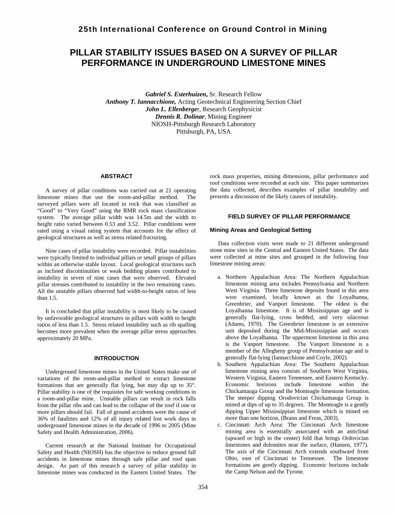
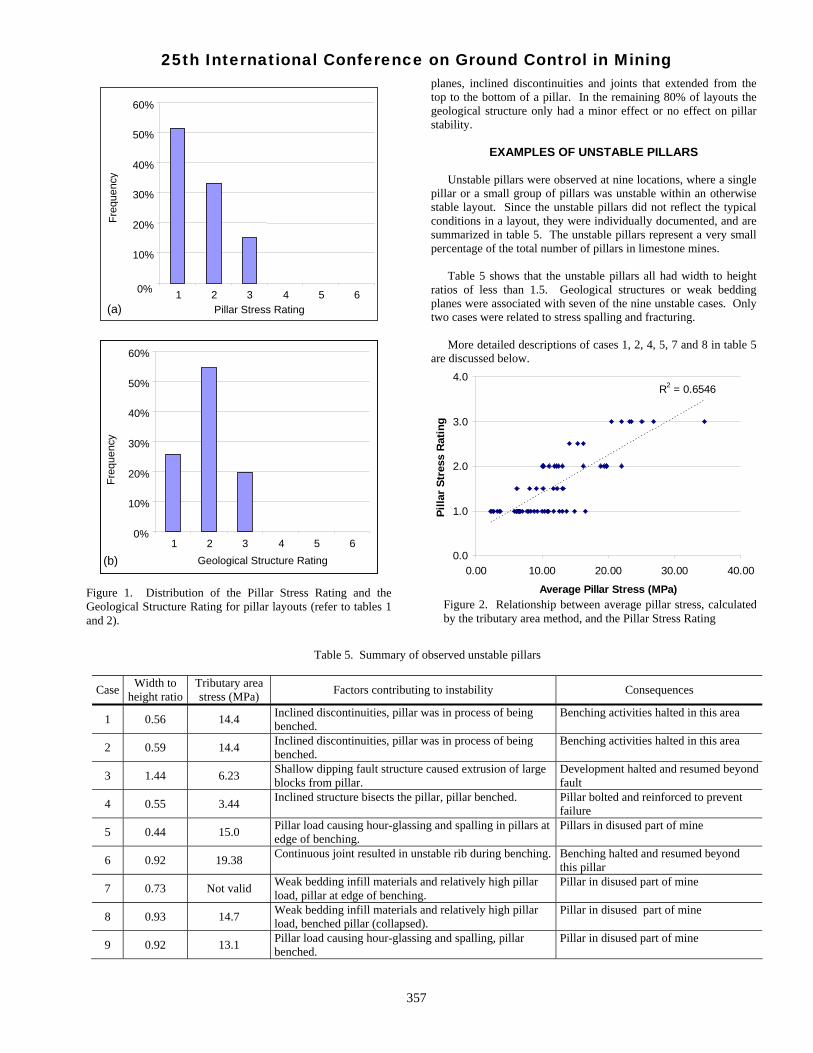
Pillar Conditions The pillar survey did not reveal any cases in which an entire array of pillars had collapsed. The distributions of observed pillar conditions are presented in figure 1, based on the Pillar Stress Rating (PSR) in table 1 and the Geological Structure Rating (GSR) in table 2. Note that the ratings refer to the general condition of the pillars in a layout, and not the condition of an individual pillar. Figure 1a shows that 85% of all layouts visited had PSR values of 1 or 2, implying “None” to “Minor” stress related damage. Only 15% of cases were rated as “Moderate”. The relationship between the average pillar load in a layout and the PSR is shown in figure 2. The pillar stress was determined by the tributary area method, based on measurements of pillar dimensions and the depth of cover. The results show that stress related fracturing can become “moderate” as the average pillar stress approaches and exceeds 20 MPa. It was observed that mine operators installed rib support in some of the pillars rated as “moderate” to maintain safe working conditions. Regarding geological structure effects, figure 1b shows that 20% of pillar layouts visited had GSR rating of 3, implying “Moderate” pillar damage caused by geological structures. These were caused by a variety of structures, including weak bedding
Table 3. Summary of rock mass classification data
Range of Ratings Parameter Descriptive observations Maximum
Possible RatingAverage Rating Minimum Maximum
Intact rock strength Strong to very strong rock, UCS typically 80-150 MPa 15 14.6 11 15
Joint frequency Average frequency is 1.72 joints per m. Range is typically 1 to 5 joints per m. 40 23.3 14 30
Joint roughness Rough to slightly rough joint surfaces, bedding joints generally very rough 6 4.5 2 6
Joint infill thickness Generally no infill, isolated cases of calcite filling observed. 6 5.5 1 6
Joint fill strength If present, soft calcite infill, occasionally clayey 6 5.7 3 6
Joint weathering Joint walls generally unweathered, hard rock 6 6.0 4 5
Joint length Joint continuity typically in 1-3 m range 6 3.9 1 6
Groundwater Typically dry, occasional damp conditions observed 15 15 12 15
RMR 100 78 64 89
25th International Conference on Ground Control in Mining
357
planes, inclined discontinuities and joints that extended from the top to the bottom of a pillar. In the remaining 80% of layouts the geological structure only had a minor effect or no effect on pillar stability.
EXAMPLES OF UNSTABLE PILLARS
Unstable pillars were observed at nine locations, where a single pillar or a small group of pillars was unstable within an otherwise stable layout. Since the unstable pillars did not reflect the typical conditions in a layout, they were individually documented, and are summarized in table 5. The unstable pillars represent a very small percentage of the total number of pillars in limestone mines. Table 5 shows that the unstable pillars all had width to height ratios of less than 1.5. Geological structures or weak bedding planes were associated with seven of the nine unstable cases. Only two cases were related to stress spalling and fracturing. More detailed descriptions of cases 1, 2, 4, 5, 7 and 8 in table 5 are discussed below.
Table 5. Summary of observed unstable pillars
Case Width to height ratio
Tributary area stress (MPa) Factors contributing to instability Consequences
1 0.56 14.4 Inclined discontinuities, pillar was in process of being benched.
Benching activities halted in this area
2 0.59 14.4 Inclined discontinuities, pillar was in process of being benched.
Benching activities halted in this area
3 1.44 6.23 Shallow dipping fault structure caused extrusion of large blocks from pillar.
Development halted and resumed beyond fault
4 0.55 3.44 Inclined structure bisects the pillar, pillar benched. Pillar bolted and reinforced to prevent failure
5 0.44 15.0 Pillar load causing hour-glassing and spalling in pillars at edge of benching.
Pillars in disused part of mine
6 0.92 19.38 Continuous joint resulted in unstable rib during benching. Benching halted and resumed beyond this pillar
7 0.73 Not valid Weak bedding infill materials and relatively high pillar load, pillar at edge of benching.
Pillar in disused part of mine
8 0.93 14.7 Weak bedding infill materials and relatively high pillar load, benched pillar (collapsed).
Pillar in disused part of mine
9 0.92 13.1 Pillar load causing hour-glassing and spalling, pillar benched.
Pillar in disused part of mine
Figure 2. Relationship between average pillar stress, calculated by the tributary area method, and the Pillar Stress Rating
R2 = 0.6546
0.0
1.0
2.0
3.0
4.0
0.00 10.00 20.00 30.00 40.00
Average Pillar Stress (MPa)
Pilla
r St
ress
Rat
ing
Figure 1. Distribution of the Pillar Stress Rating and the Geological Structure Rating for pillar layouts (refer to tables 1 and 2).
0%
10%
20%
30%
40%
50%
60%
1 2 3 4 5 6Pillar Stress Rating (a)
Freq
uenc
y .
0%
10%
20%
30%
40%
50%
60%
1 2 3 4 5 6Geological Structure Rating(b)
Freq
uenc
y .

25th International Conference on Ground Control in Mining
358
Mine A: Northern Appalachian Area Pillar instability during bench mining of the floor occurred at several instances in a Northern Appalachian mine in the Loyalhanna Limestone. The pillars were observed to have a higher occurrence of continuous geological structures, in the form of through-going angular bedding joints, than elsewhere in the country (Iannacchione and Coyle, 2002). These bedding joints had a dramatic effect on pillar strength when they were oriented at angles that permitted these structures to daylight on either side of the pillar (Iannacchione, 1999). The average rock mass properties at this mine are summarized in table 6, showing an RMR value of 78, which is described as “Good Rock”.
Table 6. Average Rock Mass Rating at Mine A
Parameter Value RatingIntact rock strength
>200 MPa 15
Joint Frequency 1.6 joints/m 23 Joint Condition Slightly rough to rough joints with no
infill, poorly developed bedding planes, joint walls unaltered
25
Groundwater Dry 15 Total: 78
The pillars in the layout were square, 10.4 m (34 ft) wide, and 8.2 m (27 ft) high on development. The room width was 13.4 to 14.6 m (44 to 48 ft). Floor benching increased the pillar height to 18.6 m (61 ft), which reduced the width to height ratio from 1.3 to 0.56 in one case, (Case 1 in table 5). The height was 17.6 m (58 ft) in the second case (Case 2 in table 5). The depth of cover was approximately 91 m (300 ft) in the areas where instabilities occurred. The average pillar stress in this layout is approximately 14.4 MPa (2,080 psi). Figure 3 shows two pillars that became unstable during benching. The large angular discontinuities prominent in the photographs did not open or extend until benching occurred. The structures are often very difficult to see on development, when the pillar width-to-height ratios are typically greater than 1.0. They are most likely to be recognized when benching occurs and greater pillar heights expose more structures and additional bench blasting loosens the rock associated with these discontinuities. In both cases, benching could not be completed around the pillars for fear of total pillar collapse. Mine B: Cincinnati Arch Area A single collapsed pillar within a layout of otherwise stable pillars was observed at a limestone mine within the Cincinnati Arch area, (Case 8 in table 5). A photograph of the failed pillar is presented in figure 4, which shows that a portion of the roof at the pillar location had failed. The pillars in this layout are square in plan and had been initially developed at a height of 7.0 m (23 ft) and a width of 13.7 m (45 ft). The planned room width was 9.1 m (30 ft) and the depth of cover is approximately 204 m (670 ft). Benching had been carried out to a height of approximately 14.6 m (48 ft), reducing the planned width-to-height ratio of the pillars from 1.95 to 0.93. The average rock mass rating in the vicinity of the collapsed pillar was 64 units, shown in table 7.
Figure 4. Stump of failed pillar at Mine B, showing roof failure at location of pillar and limited spalling of adjacent pillars (Case 8 in table 5).
Figure 3. Partially benched pillars that became unstable during benching at Mine A (Cases 1 and 2 in table 5). Figure 3a shows failure along two discontinuities while figure 3b shows evidence of multiple discontinuities.
(b)
(a)

25th International Conference on Ground Control in Mining
359
Table 7. Rock Mass Rating parameters in vicinity of failed pillar, Mine B
Parameter Value Rating
Intact rock strength 120 – 150 MPa 12 Joint Frequency 2.8-4.3 joints/m 18
Joint Condition
Slightly rough to rough joints with no infill, bedding joints contain 5mm weak fill, joint walls unaltered
24
Groundwater Damp 10 Total: 64
Of particular importance is the presence of bedding joints spaced between 0.3m and 1m (1 – 3.3 ft) apart. Some of the bedding joints contain a soft white infill material, up to 12 mm (0.5 inch) in thickness. The area was otherwise free of continuous geological structures. The rock mass in the area was damp. The area had been mined more than 5 years before the pillar failure occurred and had been used to dispose of fine limestone byproduct by hydraulic placement. The progression of pillar instability and ultimate failure was not observed by the mine staff, since the pillar was located in a disused area of the mine. The surrounding pillars are generally stable, some signs of instability were observed in the form of minor rib spalling in the adjacent pillars, seen to the right of figure 4. The roof span between the remaining pillars was about 32 m (105 ft). It is not known whether the roof failure was simultaneous with the pillar collapse or not. The average pillar stress in this layout is 14.7 MPa (2,100 psi), based on tributary area calculations using specific weight of overburden of 2.6.
The cause of the failure is thought to be a combination of several factors including the weak bands in the pillar, the relatively large overburden load and the moist conditions in the area of the failure. Pillar instability observed elsewhere in the mine showed that progressive spalling of the pillar ribs is bounded by the weak bedding layers, as shown in figure 5, (Case 7 in table 5). These
weak bedding layers are not present at all locations in the mine. The fact that only a single pillar failed indicates that the surrounding pillars are sufficiently strong to carry the additional load that was transferred from the failed pillar. The failed pillar and unstable pillars at this mine represent a very small fraction of the total number of otherwise stable pillars in the mine. Mine C: Southern Appalachian Area Brittle spalling resulting in hourglass formation at relatively low stress was observed at a mine in the southern Appalachian area, case 5 in table 5. In the area of concern, the pillars were square with side dimensions varying between about 12.2 and 15.2 m (40-50 ft) and were initially benched to 15.8 m (52 ft) high. Further benching was partially carried out, which increased the pillar height up to 27 m (90 ft). The room width was measured to be 16.4 m (53 ft), and the depth of cover is 140 m (464 ft). The width to height ratio of the benched pillars was as low as 0.44 in the 27 m (90 ft) high area and 0.77 in the 15.8 m (52 ft) high area. The limestone is a strong rock mass with an average UCS of 150 MPa (22,000 psi). Jointing is near vertical with an average spacing of about 50 cm (1.6 ft). Joint surfaces are rough, and the joint continuity is less than 3 m (10 ft). Bedding joints are poorly developed and did not appear to affect the pillar stability. The rock mass rating for this area was determined to be 78 units as shown in table 8.
Table 8. Rock Mass Rating parameters in vicinity of unstable pillar, Mine C
Parameter Value Rating
Intact rock strength 150 MPa 14 Joint Frequency 2.0 joints/m 21 Joint Condition Rough joints with no infill, poorly
developed bedding, joint walls unaltered
28
Groundwater Dry 15 Total: 78 The pillars were about 15 years old but benching had been carried out less than 5 years ago. A number of pillars were reported to be progressively spalling to the current hourglass shape, as shown in figure 6. Inspection of the pillars revealed that open vertical fractures or joints existed in the pillar ribs. Evidence of fracture through intact rock and slab formation was seen. Columnar fragments of rock about 2 to 3 m long were scattered about the pillars, as seen in the foreground. The presence of near-vertical open fractures and open joints seems to confirm that stress related failure is taking place in these pillars. The effect of benching and the irregular pillar sizes in this area are thought to have resulted in local pillar stresses in excess of the 15 MPa (2,200 psi) that the tributary area method would predict.
Figure 5. Pillar instability observed in Mine B, showing the influence of weak bedding layers (Case 7 in table 5).

25th International Conference on Ground Control in Mining
360
Mine D: Southern Appalachian Area Pillar instability was caused at this mine by the presence of a single continuous geological structure that intersected one pillar, shown in figure 7 (Case 4 in table 5). The limestone formation dips at about 30 degrees and is mined using a room and pillar layout. In the area where the unstable pillar is located, the roof of the workings was excavated to a 30 degree bedding plane, while the floor was mined in horizontal steps. The general rock mass classification in the area was found to be 76, shown in table 9.
Table 9. Rock Mass Rating parameters in vicinity of unstable pillar, Mine D
Parameter Value Rating
Intact rock strength 120 - 150 MPa 12 Joint Frequency 1.4 joints/m 24
Joint Condition Rough, discontinuous with no infill, poorly developed bedding planes
25
Groundwater Dry 15 Total: 76 The unstable pillar was located near the outcrop of the mine workings, under about 80m (260 ft) of cover. The pillar dimensions in the area are 15.3 m x 15.3 m (50 ft) and the room width is about 13 m (43 ft) The pillar height is 29 m (95 ft) resulting in a width to height ratio of 0.55. The average pillar stress is calculated as 3.4 MPa (500 psi), assuming tributary loading. Special support measures were installed to prevent deterioration and failure of the pillar. Holes were drilled through the pillar and long thread-bars were installed to provide interior reinforcement and provide active resistance to shearing along the inclined discontinuity. Additional bolting was installed to preserve the pillar ribs. The support measures have been successful and the pillar has remained stable for more than 30 years.
SUMMARY AND CONCLUSIONS
Nine cases of pillar instability were recorded at 21 underground limestone mine operations in the Eastern United States. Pillar instabilities were limited to a single pillar or a small group of pillars within otherwise stable layouts. An assessment of the unstable pillars showed that:
• Local geological structures, such as inclined discontinuities or weak bedding layers, were identified as the main contributing factor to pillar instability in seven of the nine cases. Progressive spalling and fracturing caused by elevated pillar loads contributed to the instability of the remaining two cases.
• Geological structure related instability can occur at very low pillar loads, as low as 3.4 MPa (500 psi) in one observed case.
• Evidence of stress induced spalling and fracturing was found as the average pillar stress increased beyond about 20 MPa (2,900 psi). Some of the pillars in this stress range needed rib support to maintain safe working conditions.
• The unstable pillars all had width-to-height ratios of less than 1.5. Eight of the nine cases of instability were related to benching of the floor, which reduced the width to height ratio of the pillars. Pillars that were previously stable became unstable during benching.
The study highlights that unfavorable geologic structures can cause pillar instability in limestone mines at any depth of cover. Pillars with width to height ratios of less than 1.5 are particularly prone to this type of instability. The results also show that the prevalence of rib instability can be expected to increase as mines become deeper and stress related fracturing increases. This study forms part of a NIOSH research project that has the objective to reduce ground fall accidents in limestone mines and
Figure 6. An unstable pillar at the edge of benching operations at Mine C, showing the effect of brittle failure and spalling resulting in an hourglass shape (Case 5 in table 5).
Figure 7. Pillar instability caused by a continuous geological structure cutting through the pillar at Mine D. Thread-bar bolts that were installed right through the pillar are visible (Case 4 in table 5).

25th International Conference on Ground Control in Mining
361
will be incorporated into design guidelines for safe pillar layout design.
ACKNOWLEDGEMENTS
The authors would like to thank the staff of the mining operations visited for their willingness to show us both their successful pillar layouts as well as the less successful cases.
REFERENCES
Adams, R.W. (1970). Loyalhanna Limestone - Cross-bedding and Provenance, in Studies in Appalachian Geology - Central and Southern. ed: Fisher, C.W., Pettijohn, F.J., Reed, J.C. and Weaver, K.N., John Wiley and Sons, New York, pp. 83-100. Bieniawski, Z.T. (1989). Engineering Rock Mass Classifications. Wiley, New York. Brann, R.W. and Freas, R.C. (2003). Multiple Level Room and Pillar Mining in Limestone. SME Annual Meeting, Feb. 25-25, Preprint 03-058, 5pp. Hansen, M.C. (1977). The Geology of Ohio--the Ordovician Ohio Geological Survey, Ohio Department of Natural Resources. http://www.ohiohistorycentral.org/entry.php?rec=1379 Iannacchione, A.T. (1999). Analysis of Pillar Design Practices and Techniques for U.S. Limestone Mines. Trans. Instn. Min. Metall. (sect. A: Min. Industry), 108, September-December, pp. A152-A160. Iannacchione, A.T. and Coyle, P.R. (2002). An Examination of the Loyalhanna Limestone's Structural Features and their Impact on Mining and Ground Control Practices. Proceedings, 21st International Conference on Ground Control in Mining Morgantown WV, Aug. 6-8, pp. 218-227.
Krauland, N. and Soder, P.E. (1987). Determining Pillar Strength From Pillar Failure Observations. Eng. Min. Journal, 8:34-40. Lane, W.L., Yanske, T.R. and Roberts, D.P. (1999) Pillar Extraction and Rock Mechanics at the Doe Run Company in Missouri 1991 to 1999. Proceedings, 37th Rock Mech. Symp. Amadei, Kranz, Scott & Smeallie (eds), Balkema Rotterdan, pp. 285 – 292. Laubscher, D.H. (1990). A Geomechanics Classification System for the Rating of Rock Mass in Mine Design. J. S. Afr. Inst. Min. & Metall., 90(10):257-273. Lunder, P.J. (1994). Hard Rock Pillar Strength Estimation an Applied Approach. M.A.Sc. Thesis, Dept. Mining and Mineral Process Engineering, University of British Columbia. Mine Safety & Health Administration, (2006). Web page: www.msha.gov/stats. Pritchard, C.J. and Hedley, D.G.F. (1993). Progressive Pillar Failure and Rockbursting at Denison Mine. Rockburst and Seismicity in Mines, Young (ed.). Balkema, Rotterdam. Siefert, M., Mali, H., Wagner, H. and Frommer, T. (2003). Geotechnical Risk Assessment of an Underground Magnesite Mine. Proceedings, Technology Roadmap for Rock Mechanics, S. Afr. Inst. Min. Metall., pp 1073-1076. Swann, D.H. (2006). A Summary: Geologic History of the Illinois Basin. Web page:www.ioga.com/Geohist.htm. U.S. Geological Survey (2006). Paleontology web page: geology.er.usgs.gov/paleo.