Embed Size (px)
Citation preview
Pilot and bench scale fuel characterisation
service for plant investors
Toni Pikkarainen
Jyväskylä, 23rd September 2014
VTT Technical Research Centre of Finland
2
Content
Introduction to fluidized bed combustion
Development of fluidized bed combustion technology
Characterization services
Test rigs
Results
References
Case examples
Summary
3
COMBUSTION
GASIFICATION
PYROLYSIS
CATALYTIC PROCESSES
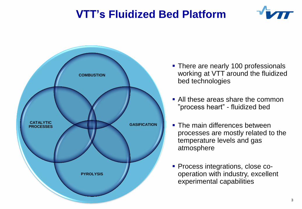
VTT’s Fluidized Bed Platform
There are nearly 100 professionals working at VTT around the fluidized bed technologies
All these areas share the common ”process heart” - fluidized bed
The main differences between processes are mostly related to the temperature levels and gas atmosphere
Process integrations, close co-operation with industry, excellent experimental capabilities
4 23/09/2014 4
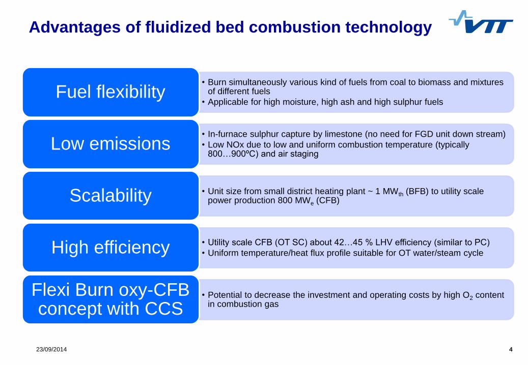
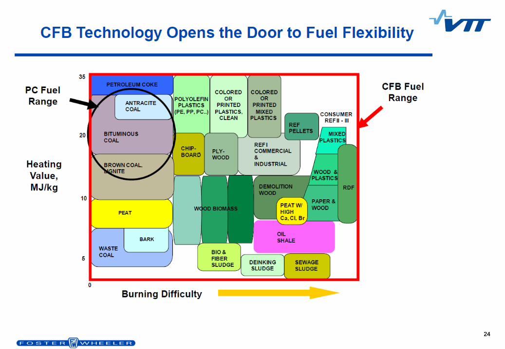
Advantages of fluidized bed combustion technology
• Burn simultaneously various kind of fuels from coal to biomass and mixtures of different fuels
• Applicable for high moisture, high ash and high sulphur fuels Fuel flexibility
• In-furnace sulphur capture by limestone (no need for FGD unit down stream)
• Low NOx due to low and uniform combustion temperature (typically 800…900ºC) and air staging
Low emissions
• Unit size from small district heating plant ~ 1 MWth (BFB) to utility scale power production 800 MWe (CFB) Scalability
• Utility scale CFB (OT SC) about 42…45 % LHV efficiency (similar to PC)
• Uniform temperature/heat flux profile suitable for OT water/steam cycle High efficiency
• Potential to decrease the investment and operating costs by high O2 content in combustion gas
Flexi Burn oxy-CFB concept with CCS
5 23/09/2014 5
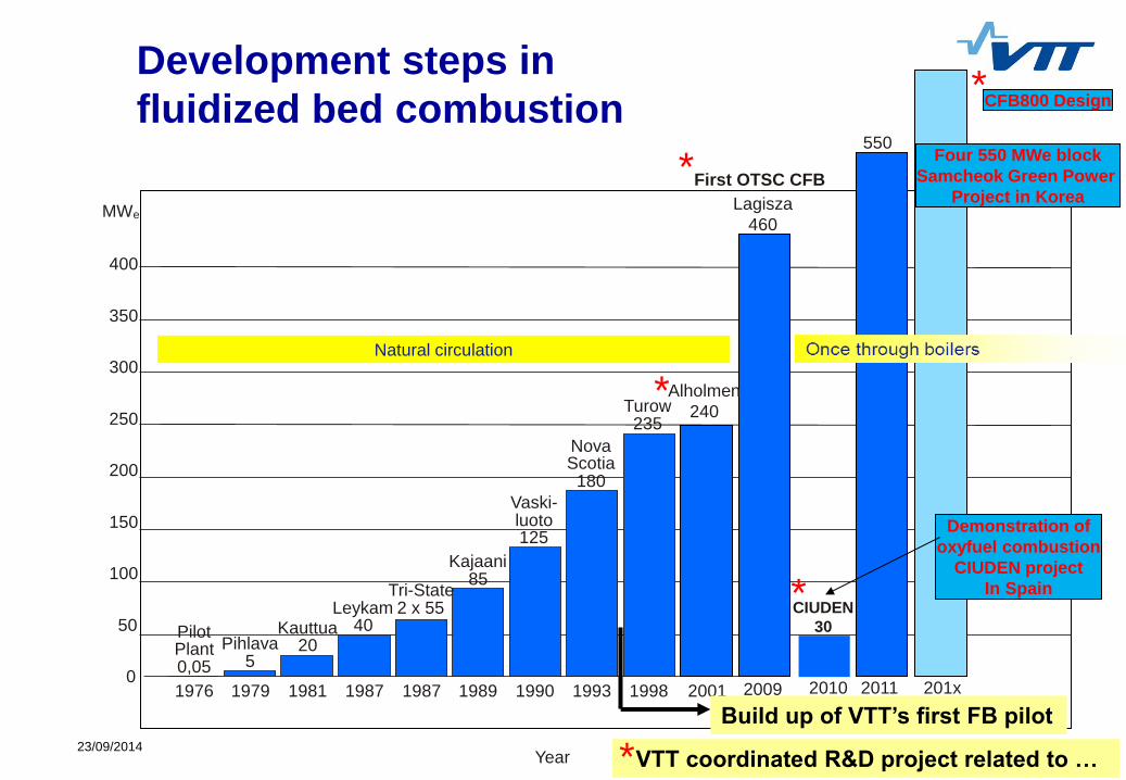
Development steps in
fluidized bed combustion
0
50
100
150
200
250
300
350
400
1976
Pilot Plant 0,05
Pihlava 5
Kauttua 20
Leykam 40
Tri-State 2 x 55
Kajaani 85
Vaski- luoto 125
Nova Scotia
180
Turow 235
MWe
1979 1981 1987 1987 1989
Year
1990 1993 1998
Alholmen
240
2001
Natural circulation
First OTSC CFB
Lagisza
460
2009 2010 2011
CIUDEN
30
VTT coordinated R&D project related to …
*
*
*
*
550
Build up of VTT’s first FB pilot
Four 550 MWe block
Samcheok Green Power
Project in Korea
Demonstration of
oxyfuel combustion
CIUDEN project
In Spain
* CFB800 Design
201x
6 23/09/2014 6
500
550
600
650
700
750
800
850
900
2001 2003 2005 2007 2009 2011
CO
2e
mis
sio
n [k
g/M
Wh
ele
ctr
icit
y]
Year
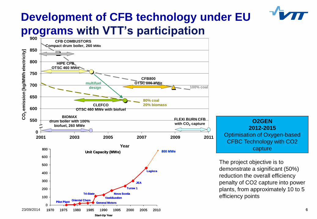
CFB COMBUSTORS
Compact drum boiler, 260 MWe
HIPE CFB
OTSC 460 MWe
CLEFCO
OTSC 460 MWe with biofuel
0
CFB800
OTSC 800 MWe
FLEXI BURN CFB
with CO2 capture
100% coal
80% coal
20% biomass
multifuel
design
BIOMAX
drum boiler with 100%
biofuel, 260 MWe
Unit Capacity (MWe)
0
100
200
300
400
500
600
1970 1975 1980 1985 1990 1995 2000 2005 2010
Start-Up Year
Pilot PlantOriental Chem
Lagisza
JEA
Turow 1
Vaskiluodon
Nova ScotiaTri-State
General Motors
800800 MWeUnit Capacity (MWe)
0
100
200
300
400
500
600
1970 1975 1980 1985 1990 1995 2000 2005 2010
Start-Up Year
Pilot PlantOriental Chem
Lagisza
JEA
Turow 1
Vaskiluodon
Nova ScotiaTri-State
General Motors
800800 MWe
O2GEN
2012-2015
Optimisation of Oxygen-based
CFBC Technology with CO2
capture
The project objective is to
demonstrate a significant (50%)
reduction the overall efficiency
penalty of CO2 capture into power
plants, from approximately 10 to 5
efficiency points
Development of CFB technology under EU
programs with VTT’s participation
7
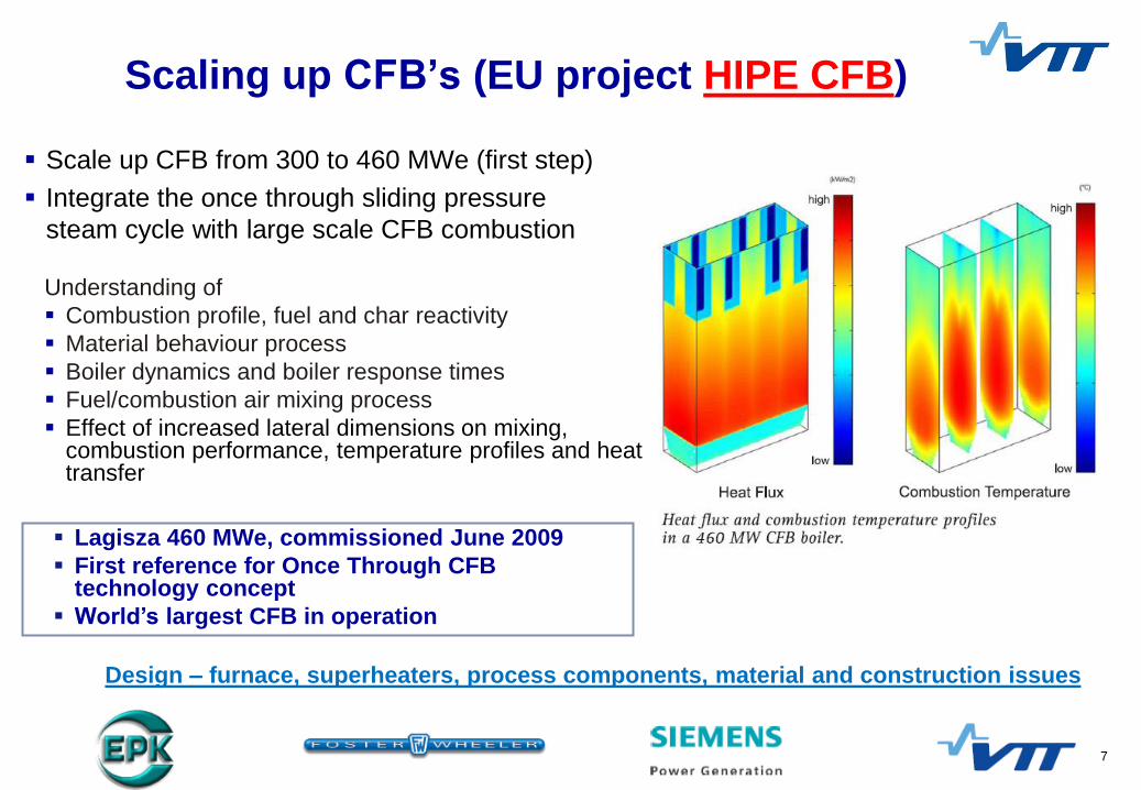
Scaling up CFB’s (EU project HIPE CFB)
Scale up CFB from 300 to 460 MWe (first step)
Integrate the once through sliding pressure
steam cycle with large scale CFB combustion
Understanding of
Combustion profile, fuel and char reactivity
Material behaviour process
Boiler dynamics and boiler response times
Fuel/combustion air mixing process
Effect of increased lateral dimensions on mixing, combustion performance, temperature profiles and heat transfer
Design – furnace, superheaters, process components, material and construction issues
Lagisza 460 MWe, commissioned June 2009
First reference for Once Through CFB technology concept
World’s largest CFB in operation
8
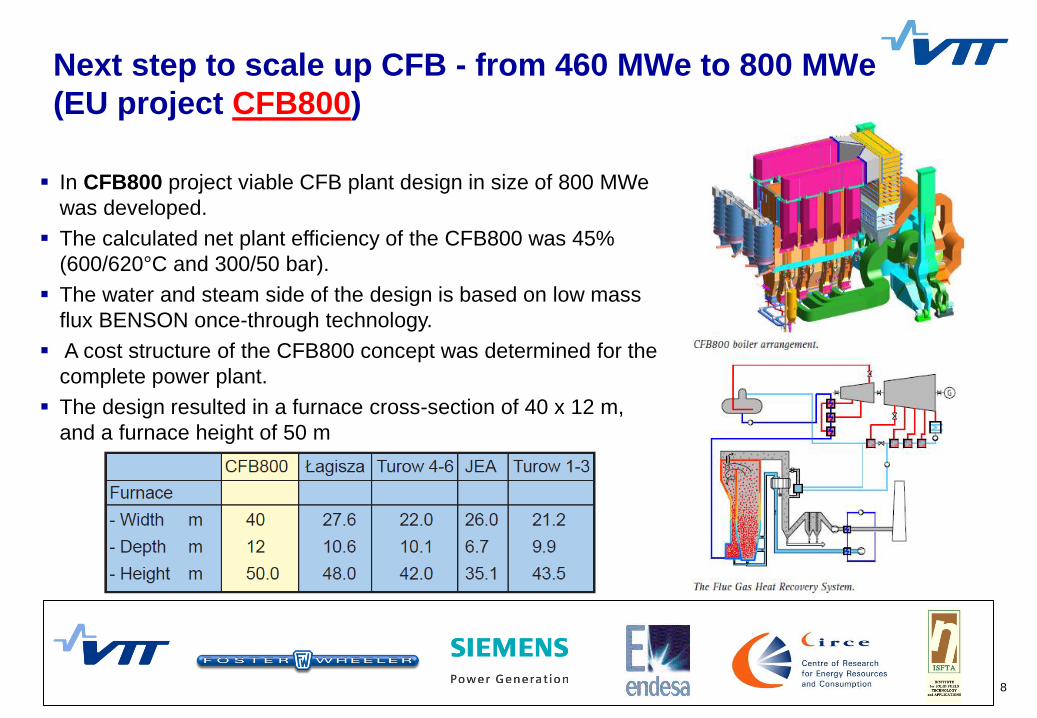
Next step to scale up CFB - from 460 MWe to 800 MWe
(EU project CFB800)
In CFB800 project viable CFB plant design in size of 800 MWe
was developed.
The calculated net plant efficiency of the CFB800 was 45%
(600/620°C and 300/50 bar).
The water and steam side of the design is based on low mass
flux BENSON once-through technology.
A cost structure of the CFB800 concept was determined for the
complete power plant.
The design resulted in a furnace cross-section of 40 x 12 m,
and a furnace height of 50 m
9
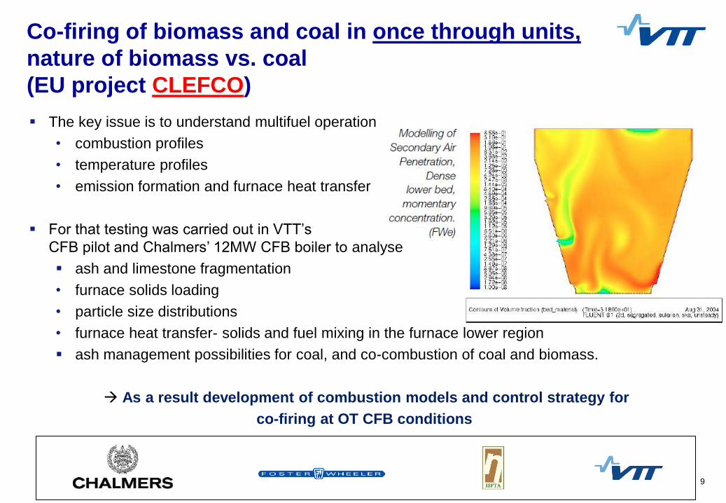
Co-firing of biomass and coal in once through units,
nature of biomass vs. coal
(EU project CLEFCO)
The key issue is to understand multifuel operation
• combustion profiles
• temperature profiles
• emission formation and furnace heat transfer
For that testing was carried out in VTT’s
CFB pilot and Chalmers’ 12MW CFB boiler to analyse
ash and limestone fragmentation
• furnace solids loading
• particle size distributions
• furnace heat transfer- solids and fuel mixing in the furnace lower region
ash management possibilities for coal, and co-combustion of coal and biomass.
As a result development of combustion models and control strategy for
co-firing at OT CFB conditions
10 23/09/2014 10
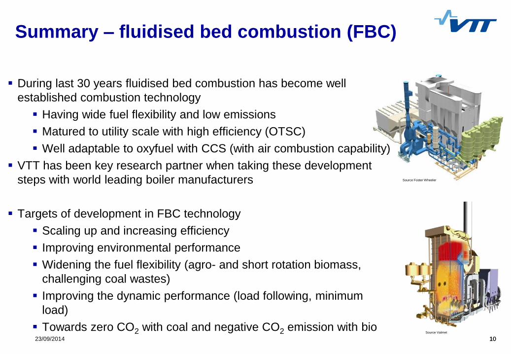
Summary – fluidised bed combustion (FBC)
During last 30 years fluidised bed combustion has become well
established combustion technology
Having wide fuel flexibility and low emissions
Matured to utility scale with high efficiency (OTSC)
Well adaptable to oxyfuel with CCS (with air combustion capability)
VTT has been key research partner when taking these development
steps with world leading boiler manufacturers
Targets of development in FBC technology
Scaling up and increasing efficiency
Improving environmental performance
Widening the fuel flexibility (agro- and short rotation biomass,
challenging coal wastes)
Improving the dynamic performance (load following, minimum
load)
Towards zero CO2 with coal and negative CO2 emission with bio
Source Foster Wheeler
Source Valmet
11 23/09/2014 11
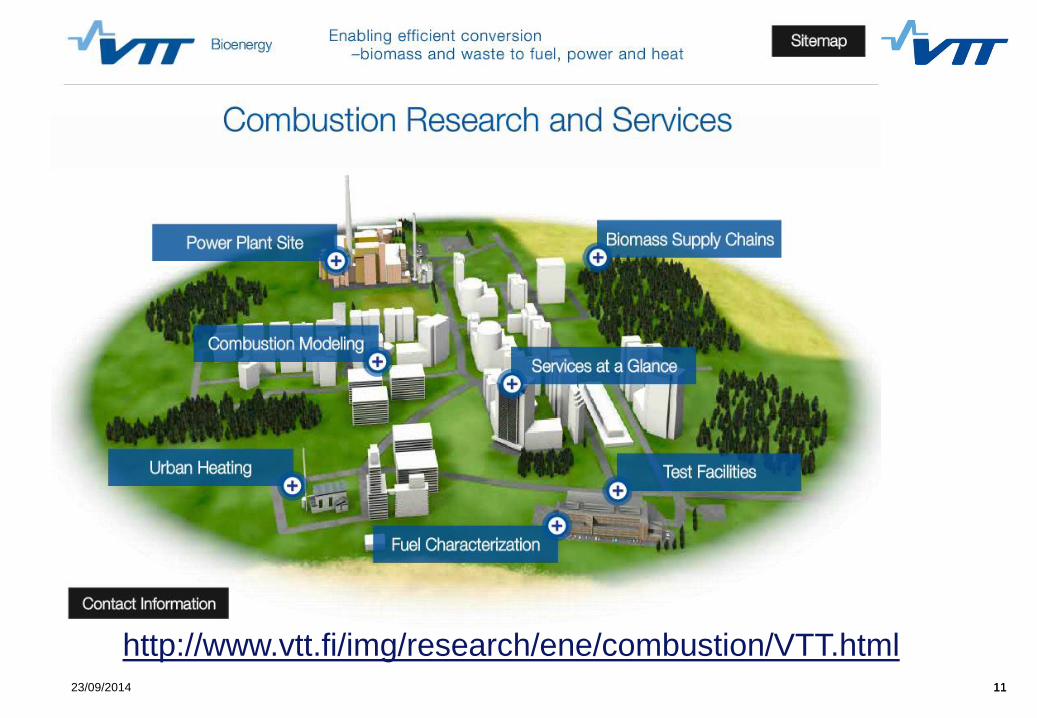
http://www.vtt.fi/img/research/ene/combustion/VTT.html
12 23/09/2014 12
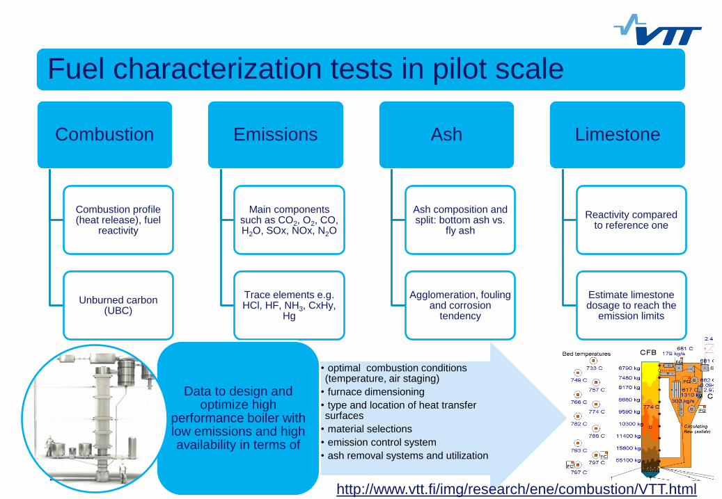
Fuel characterization tests in pilot scale
Combustion
Combustion profile (heat release), fuel
reactivity
Unburned carbon (UBC)
Emissions
Main components such as CO2, O2, CO, H2O, SOx, NOx, N2O
Trace elements e.g. HCl, HF, NH3, CxHy,
Hg
Ash
Ash composition and split: bottom ash vs.
fly ash
Agglomeration, fouling and corrosion
tendency
Limestone
Reactivity compared to reference one
Estimate limestone dosage to reach the
emission limits
• optimal combustion conditions (temperature, air staging)
• furnace dimensioning
• type and location of heat transfer surfaces
• material selections
• emission control system
• ash removal systems and utilization
Data to design and optimize high
performance boiler with low emissions and high availability in terms of
http://www.vtt.fi/img/research/ene/combustion/VTT.html
13 23/09/2014 13
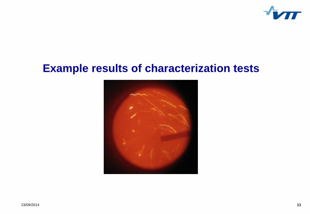
Example results of characterization tests
14 23/09/2014 14
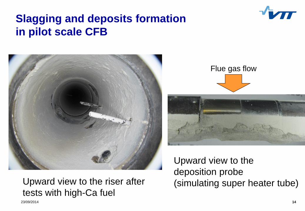
Slagging and deposits formation
in pilot scale CFB
Upward view to the riser after
tests with high-Ca fuel
Upward view to the
deposition probe
(simulating super heater tube)
Flue gas flow
15 23/09/2014 15
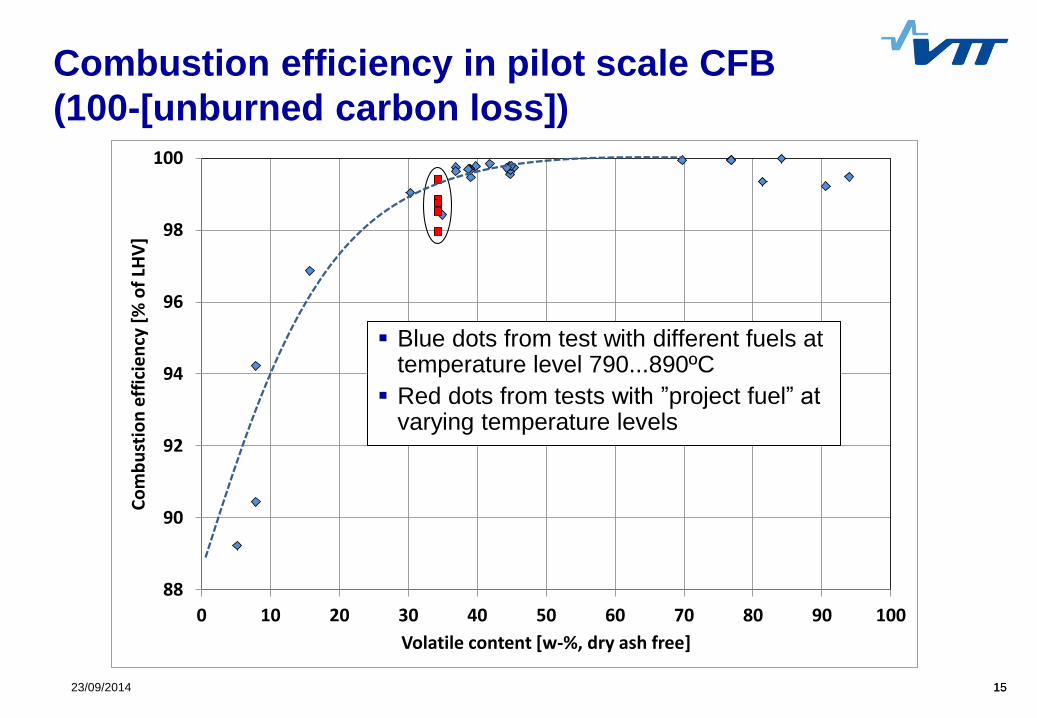
Combustion efficiency in pilot scale CFB
(100-[unburned carbon loss])
88
90
92
94
96
98
100
0 10 20 30 40 50 60 70 80 90 100
Co
mb
ust
ion
eff
icie
ncy
[%
of
LHV
]
Volatile content [w-%, dry ash free]
Blue dots from test with different fuels at temperature level 790...890ºC
Red dots from tests with ”project fuel” at varying temperature levels
16 23/09/2014 16
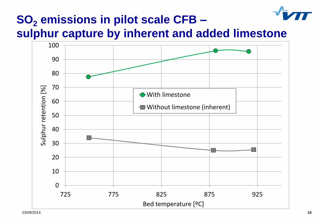
SO2 emissions in pilot scale CFB –
sulphur capture by inherent and added limestone
0
10
20
30
40
50
60
70
80
90
100
725 775 825 875 925
Sulp
hu
r re
ten
tio
n [
%]
Bed temperature [ºC]
With limestone
Without limestone (inherent)
17 23/09/2014 17
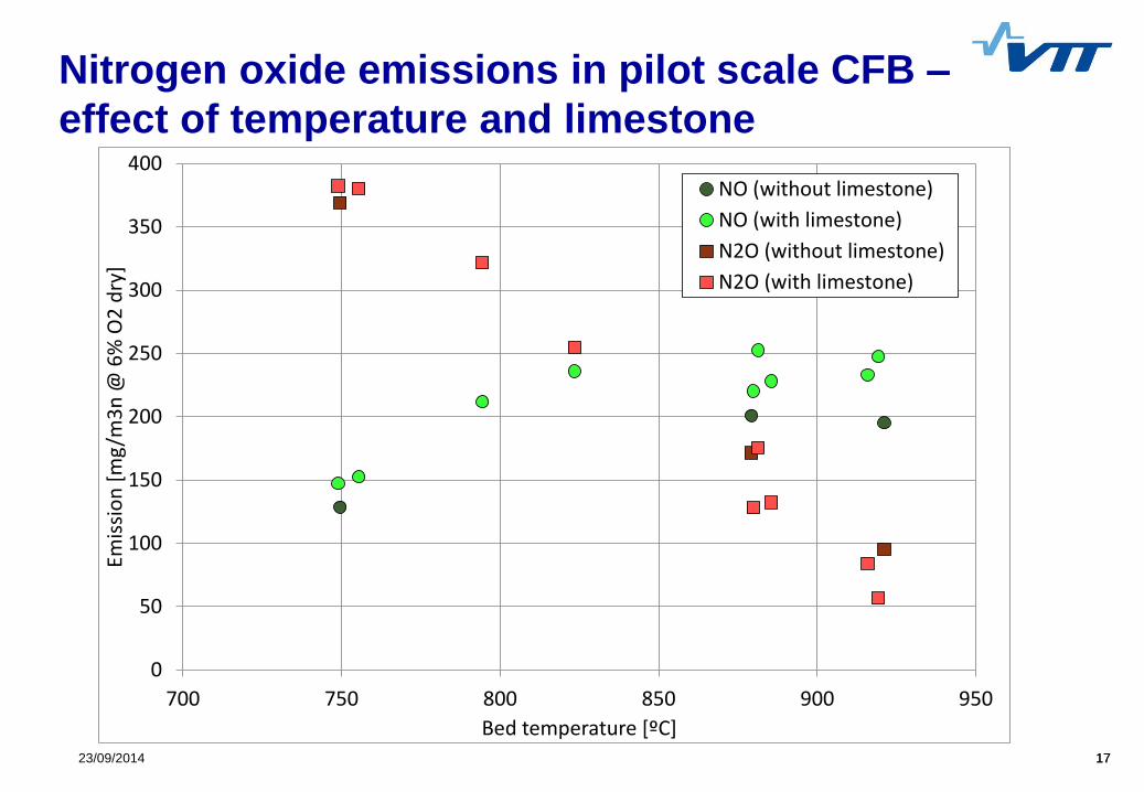
Nitrogen oxide emissions in pilot scale CFB –
effect of temperature and limestone
0
50
100
150
200
250
300
350
400
700 750 800 850 900 950
Emis
sio
n [
mg
/m3
n @
6%
O2
dry
]
Bed temperature [ºC]
NO (without limestone)
NO (with limestone)
N2O (without limestone)
N2O (with limestone)
18 23/09/2014 18
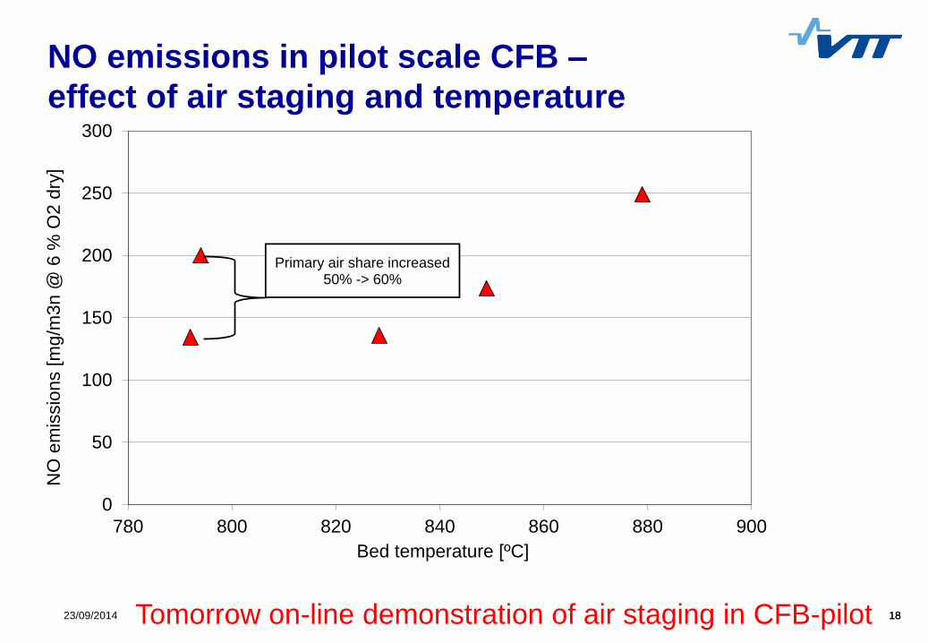
NO emissions in pilot scale CFB –
effect of air staging and temperature
0
50
100
150
200
250
300
780 800 820 840 860 880 900
NO
em
issio
ns [
mg/m
3n @
6 %
O2 d
ry]
Bed temperature [ºC]
Primary air share increased 50% -> 60%
Tomorrow on-line demonstration of air staging in CFB-pilot
19 23/09/2014 19
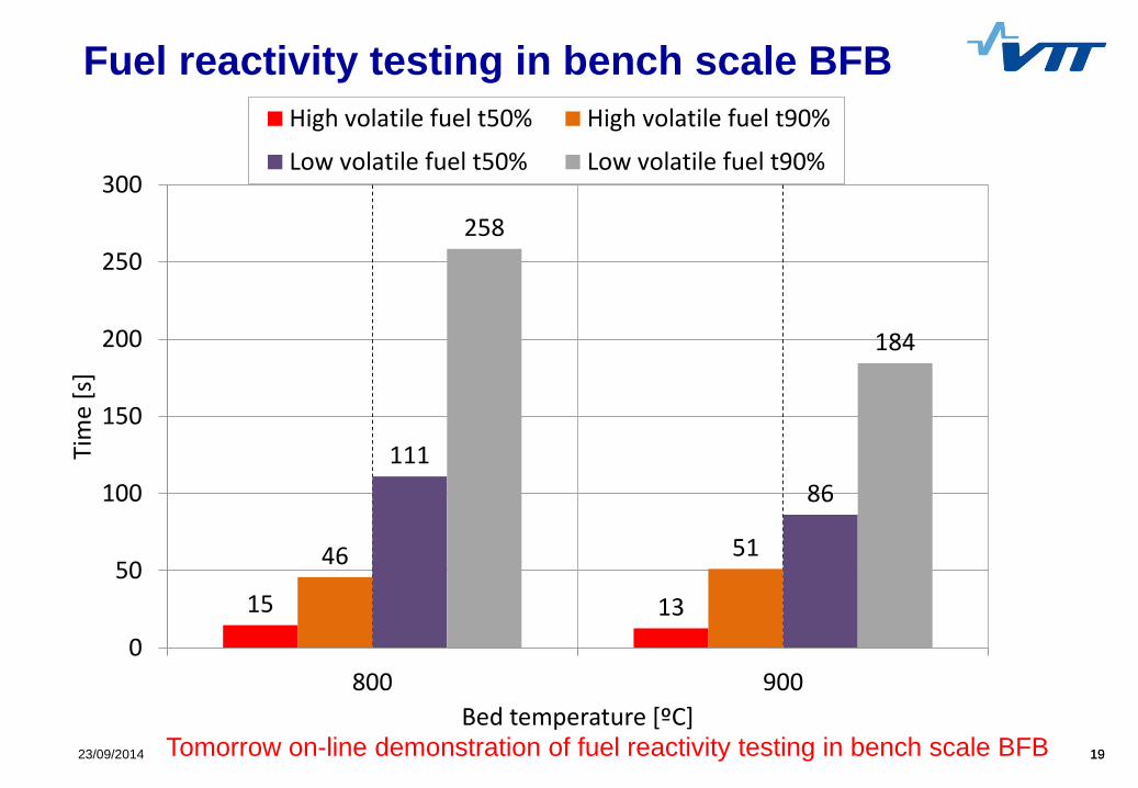
Fuel reactivity testing in bench scale BFB
15 13
46 51
111
86
258
184
0
50
100
150
200
250
300
800 900
Tim
e [s
]
Bed temperature [ºC]
High volatile fuel t50% High volatile fuel t90%
Low volatile fuel t50% Low volatile fuel t90%
Tomorrow on-line demonstration of fuel reactivity testing in bench scale BFB
20 23/09/2014 20
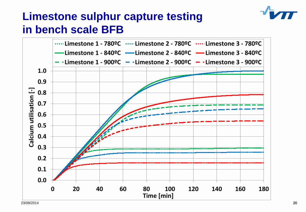
Limestone sulphur capture testing
in bench scale BFB
0.0
0.1
0.2
0.3
0.4
0.5
0.6
0.7
0.8
0.9
1.0
0 20 40 60 80 100 120 140 160 180
Cal
ciu
m u
tilis
atio
n [
-]
Time [min]
Limestone 1 - 780ºC Limestone 2 - 780ºC Limestone 3 - 780ºC
Limestone 1 - 840ºC Limestone 2 - 840ºC Limestone 3 - 840ºC
Limestone 1 - 900ºC Limestone 2 - 900ºC Limestone 3 - 900ºC
21 23/09/2014 21
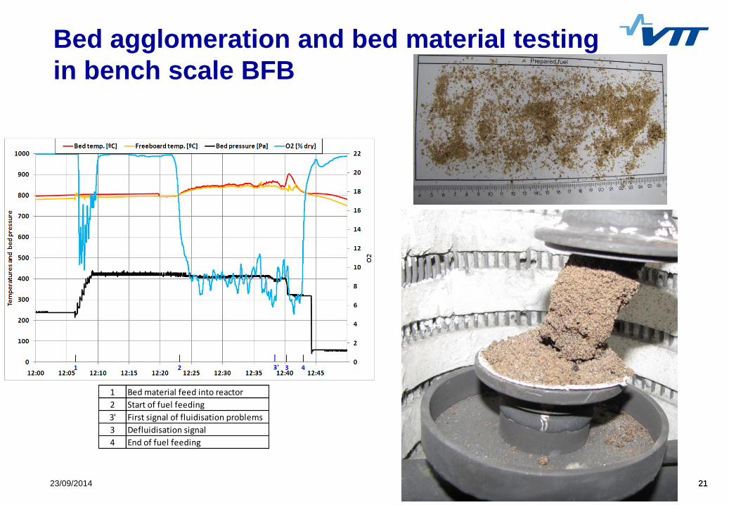
Bed agglomeration and bed material testing
in bench scale BFB
1 Bed material feed into reactor
2 Start of fuel feeding
3' First signal of fluidisation problems
3 Defluidisation signal
4 End of fuel feeding
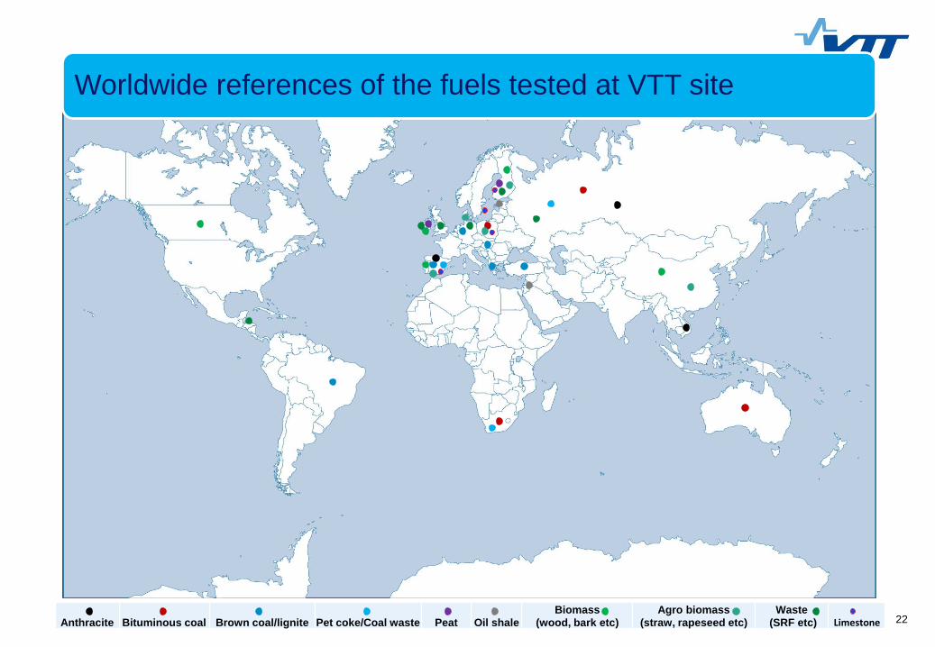
22 Anthracite Bituminous coal Brown coal/lignite Pet coke/Coal waste Peat Oil shale Biomass
(wood, bark etc) Agro biomass
(straw, rapeseed etc) Waste
(SRF etc) Limestone
Worldwide references of the fuels tested at VTT site
23 23/09/2014 23
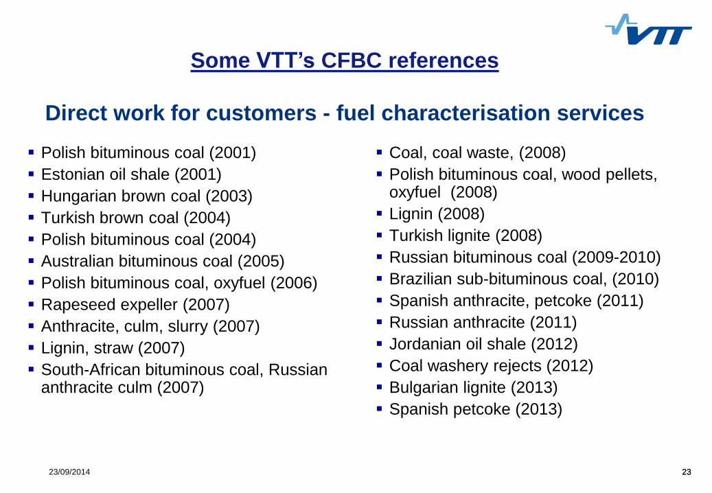
Polish bituminous coal (2001)
Estonian oil shale (2001)
Hungarian brown coal (2003)
Turkish brown coal (2004)
Polish bituminous coal (2004)
Australian bituminous coal (2005)
Polish bituminous coal, oxyfuel (2006)
Rapeseed expeller (2007)
Anthracite, culm, slurry (2007)
Lignin, straw (2007)
South-African bituminous coal, Russian anthracite culm (2007)
Some VTT’s CFBC references
Direct work for customers - fuel characterisation services
Coal, coal waste, (2008)
Polish bituminous coal, wood pellets, oxyfuel (2008)
Lignin (2008)
Turkish lignite (2008)
Russian bituminous coal (2009-2010)
Brazilian sub-bituminous coal, (2010)
Spanish anthracite, petcoke (2011)
Russian anthracite (2011)
Jordanian oil shale (2012)
Coal washery rejects (2012)
Bulgarian lignite (2013)
Spanish petcoke (2013)
24 23/09/2014 24
25
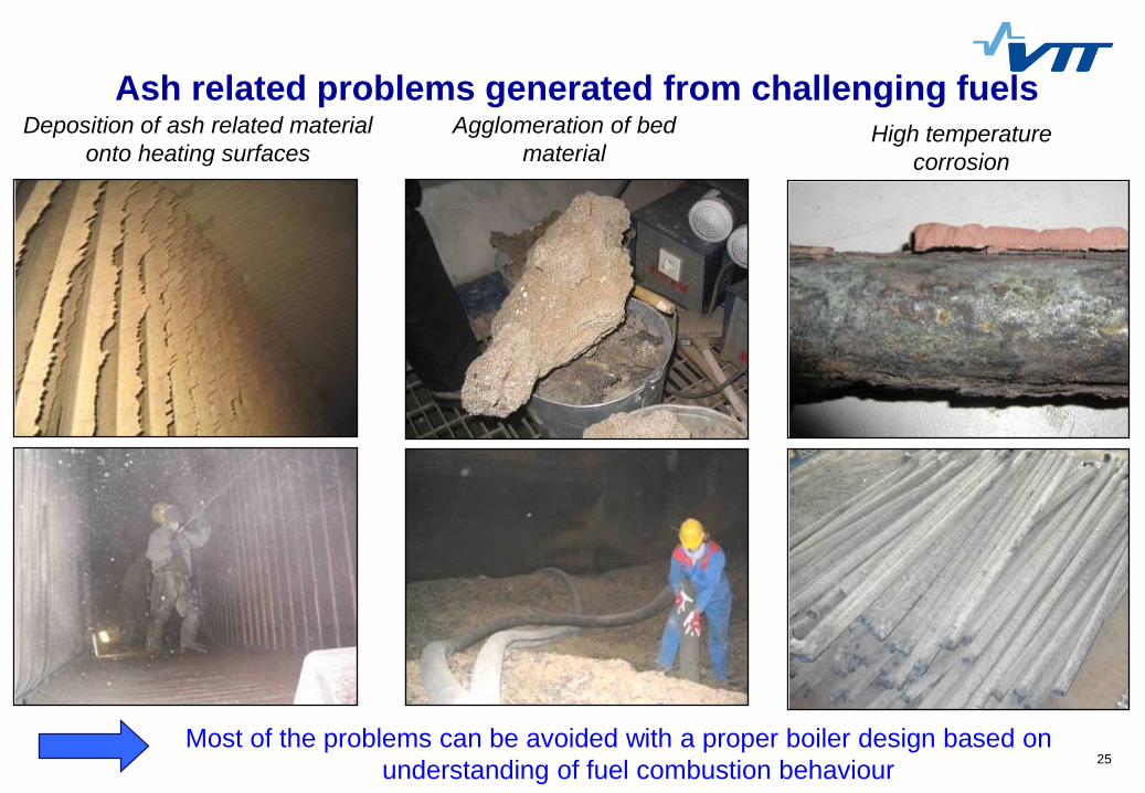
Deposition of ash related material
onto heating surfaces
Agglomeration of bed
material High temperature
corrosion
Ash related problems generated from challenging fuels
Most of the problems can be avoided with a proper boiler design based on
understanding of fuel combustion behaviour
26 23/09/2014 26
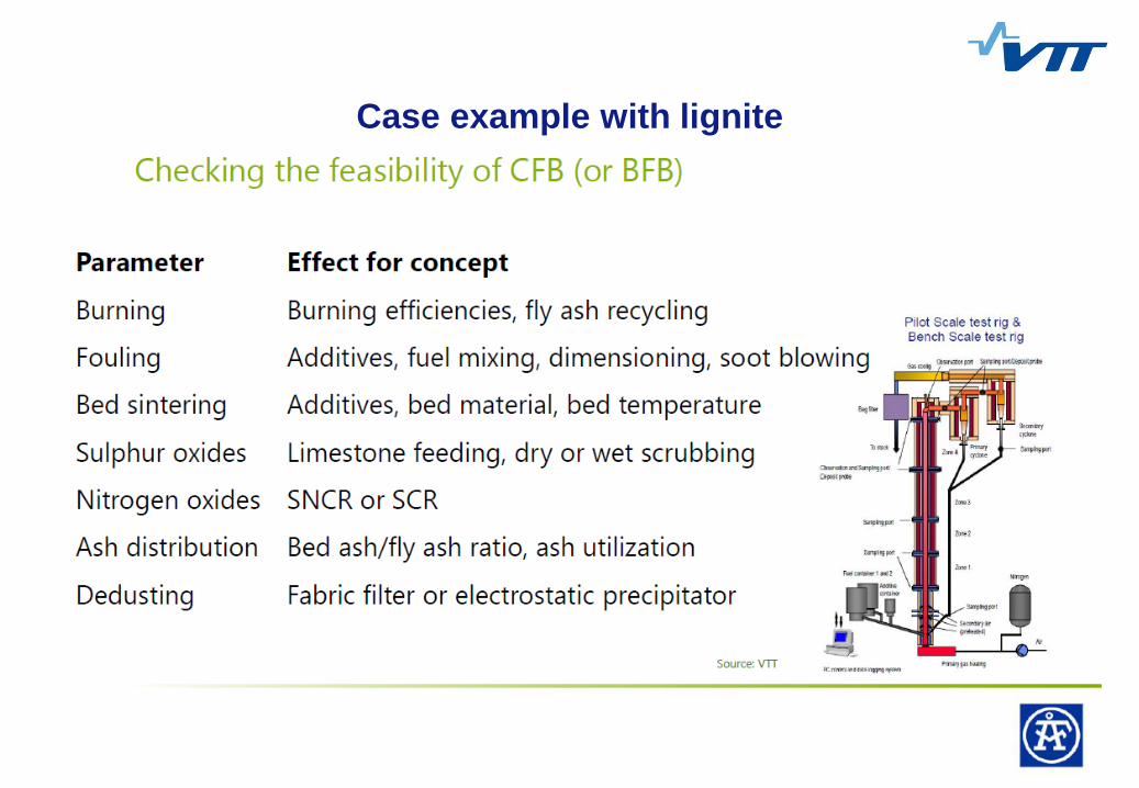
Case example with lignite
27
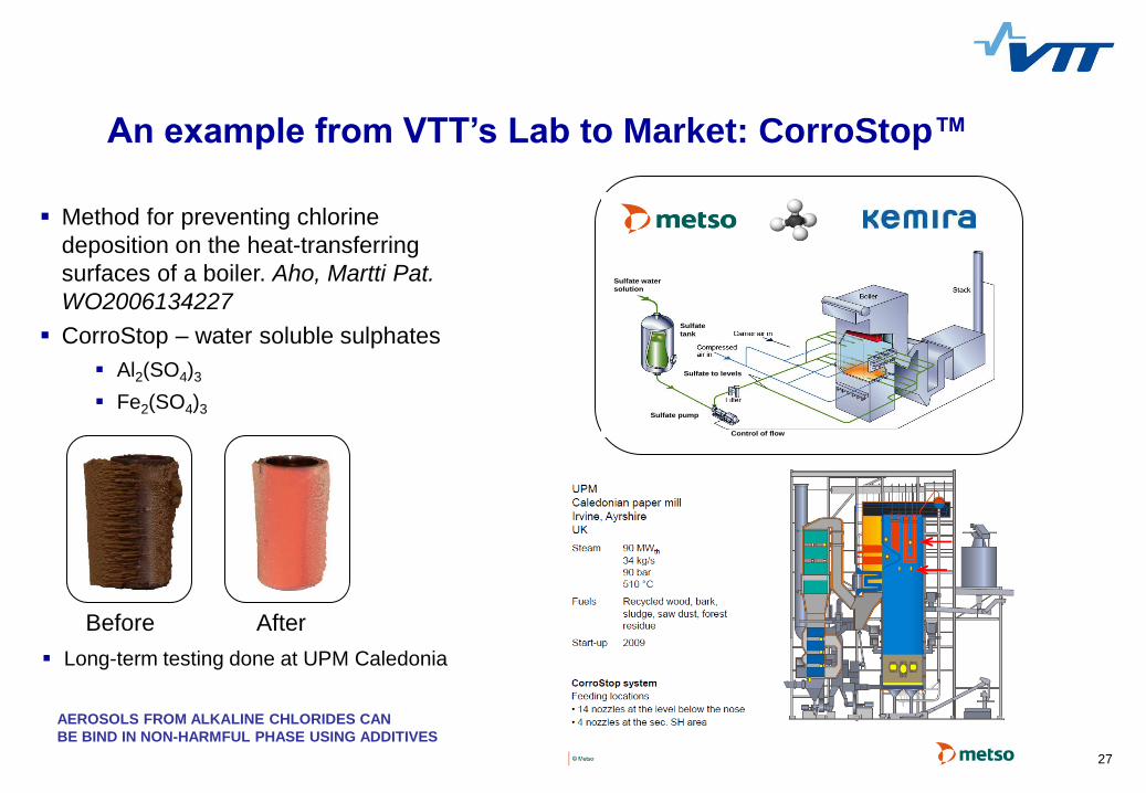
Method for preventing chlorine
deposition on the heat-transferring
surfaces of a boiler. Aho, Martti Pat.
WO2006134227
CorroStop – water soluble sulphates
Al2(SO4)3
Fe2(SO4)3
Long-term testing done at UPM Caledonia
An example from VTT’s Lab to Market: CorroStop™
Injection
nozzles
Sulfate water
solution
Sulfate in
Sulfate
tank
Sulfate to levels
Control of flow
Sulfate pump
Injection
nozzles
Sulfate water
solution
Sulfate in
Sulfate
tank
Sulfate to levels
Control of flow
Sulfate pump
Injection
nozzles
Sulfate water
solution
Sulfate in
Sulfate
tank
Sulfate to levels
Control of flow
Sulfate pump
Before After
AEROSOLS FROM ALKALINE CHLORIDES CAN
BE BIND IN NON-HARMFUL PHASE USING ADDITIVES
28 23/09/2014 28
15 %
20 %
25 %
30 %
35 %
40 %
45 %
50 %
350 400 450 500 550 600 650 700
Steam temperature, °C
Ele
ctr
ic e
ffic
ien
cy,
%
Grate fired CHP waste incinerator
420°C, 60bar
Fluidised bed CHP plant for waste
470°C, 65bar
Ultra super critical pulverised coal fired condensing
power plant, 700°C, 330bar
Super critical coal fired condencing power plant, fluidised bed
580°C, 275bar
Grate firing for MSW
Fluidised bed for SRF
Biomass
combustion
Coal fired condencing mode
power plants
Grate fired CHP plant for biomass
500°C, 70bar
ADCOF TARGET AREA:
Fluidised bed CHP plant for biomass,
520°C, 120bar
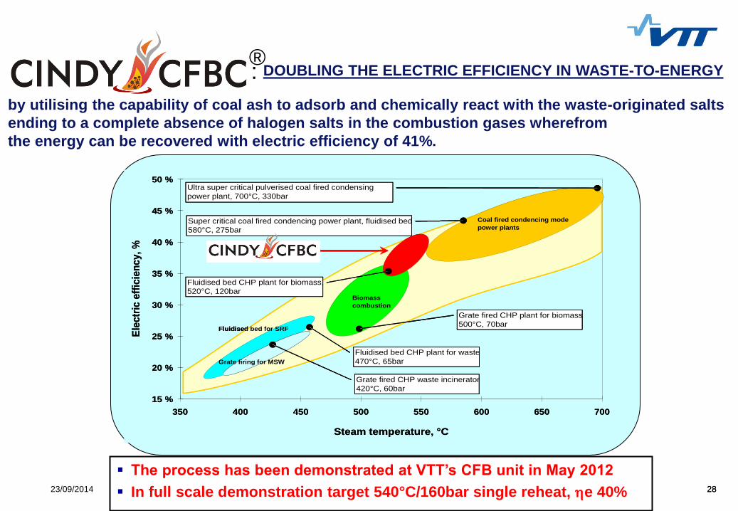
® DOUBLING THE ELECTRIC EFFICIENCY IN WASTE-TO-ENERGY :
by utilising the capability of coal ash to adsorb and chemically react with the waste-originated salts
ending to a complete absence of halogen salts in the combustion gases wherefrom
the energy can be recovered with electric efficiency of 41%.
The process has been demonstrated at VTT’s CFB unit in May 2012
In full scale demonstration target 540°C/160bar single reheat, e 40%
29 29 23/09/2014
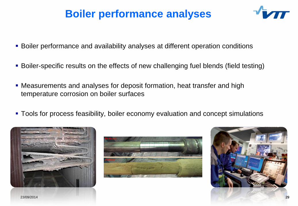
Boiler performance analyses
Boiler performance and availability analyses at different operation conditions
Boiler-specific results on the effects of new challenging fuel blends (field testing)
Measurements and analyses for deposit formation, heat transfer and high
temperature corrosion on boiler surfaces
Tools for process feasibility, boiler economy evaluation and concept simulations
30 23/09/2014 30
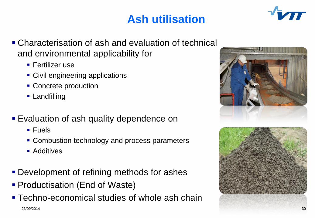
Ash utilisation
Characterisation of ash and evaluation of technical
and environmental applicability for
Fertilizer use
Civil engineering applications
Concrete production
Landfilling
Evaluation of ash quality dependence on
Fuels
Combustion technology and process parameters
Additives
Development of refining methods for ashes
Productisation (End of Waste)
Techno-economical studies of whole ash chain
31 23/09/2014 31
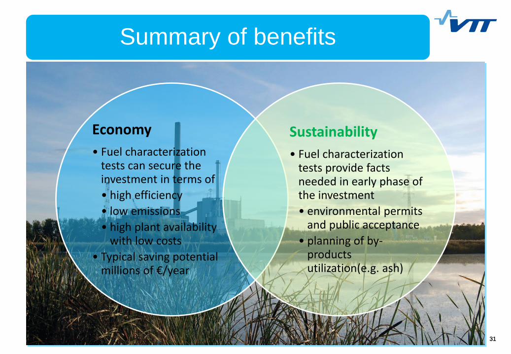
Summary of benefits
Economy
• Fuel characterization tests can secure the investment in terms of
• high efficiency
• low emissions
• high plant availability with low costs
• Typical saving potential millions of €/year
Sustainability
• Fuel characterization tests provide facts needed in early phase of the investment
• environmental permits and public acceptance
• planning of by-products utilization(e.g. ash)

TECHNOLOGY FOR BUSINESS