Embed Size (px)
Citation preview
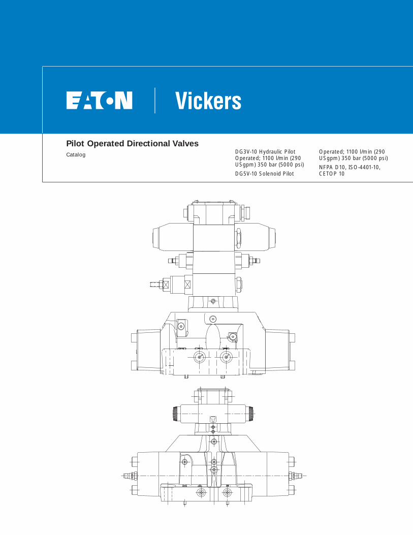
Pilot Operated Directional Valves
Catalog DG3V-10 Hydraulic PilotOperated; 1100 l/min (290USgpm) 350 bar (5000 psi)
DG5V-10 Solenoid Pilot
Operated; 1100 l/min (290USgpm) 350 bar (5000 psi)
NFPA D10, ISO-4401-10,CETOP 10
2 EATON Vickers Pilot Operated Directional Valves Catalog V-VLDI-MC004-E March 2007
Introduction
General Description
The Eaton size 10 DirectionalControl Valve serves as acontrol valve package. Thispackage is generally used tocontrol large flows, to 1100l/min (290 USgpm).
The size 10 Directional Valvehas been developed to bethe ‘‘Best in Class’’ productthrough Computation FluidDynamics and Finite ElementAnalysis.
The low pressure dropmakes it the top performer inits class.
This Directional Control Valvefeatures the following pilotvalves:
• DG3V-10 - remote pilotoperated valve.
• DG5V-10-S uses the DG4V-3S-60 standard performance pilot.
• DG5V-10-H uses the DG4V-3-60 high performance pilot.
• DG5V-10-A uses theDG5S4-01-50 air gap pilot.
• DG5V-10-F uses theDG4V4-01-10 wet armature pilot.
• DG5V-10-V uses theDG4V5-20 wet armature pilot.
• DG5V-10-W uses theDG5S4-01-60 wet armature pilot.
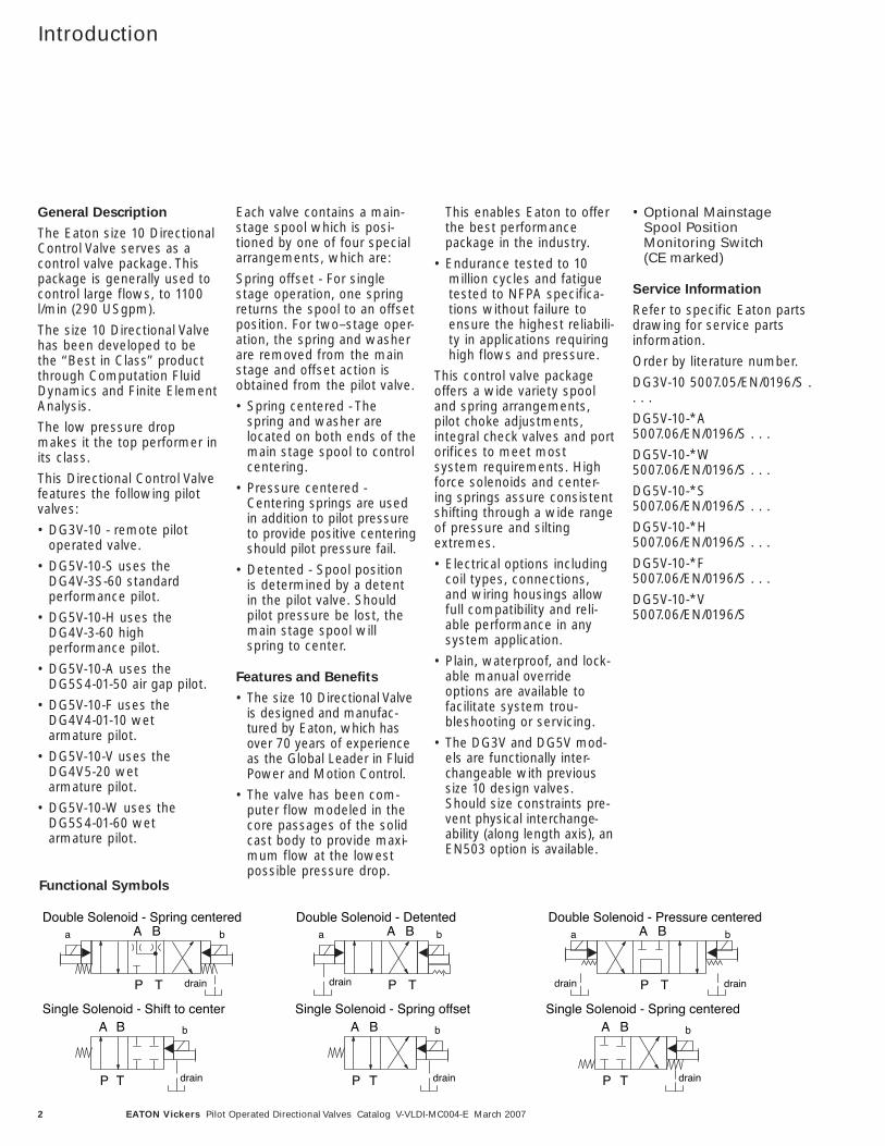
Each valve contains a main-stage spool which is posi-tioned by one of four specialarrangements, which are:
Spring offset - For singlestage operation, one springreturns the spool to an offsetposition. For two–stage oper-ation, the spring and washerare removed from the mainstage and offset action isobtained from the pilot valve.
• Spring centered - Thespring and washer arelocated on both ends of themain stage spool to controlcentering.
• Pressure centered -Centering springs are usedin addition to pilot pressureto provide positive centeringshould pilot pressure fail.
• Detented - Spool positionis determined by a detentin the pilot valve. Shouldpilot pressure be lost, themain stage spool willspring to center.
Features and Benefits
• The size 10 Directional Valveis designed and manufac-tured by Eaton, which hasover 70 years of experienceas the Global Leader in FluidPower and Motion Control.
• The valve has been com-puter flow modeled in thecore passages of the solidcast body to provide maxi-mum flow at the lowestpossible pressure drop.
This enables Eaton to offerthe best performance package in the industry.
• Endurance tested to 10 million cycles and fatiguetested to NFPA specifica-tions without failure toensure the highest reliabili-ty in applications requiringhigh flows and pressure.
This control valve packageoffers a wide variety spooland spring arrangements,pilot choke adjustments, integral check valves and portorifices to meet most system requirements. Highforce solenoids and center-ing springs assure consistentshifting through a wide rangeof pressure and siltingextremes.
• Electrical options includingcoil types, connections,and wiring housings allowfull compatibility and reli-able performance in anysystem application.
• Plain, waterproof, and lock-able manual overrideoptions are available tofacilitate system trou-bleshooting or servicing.
• The DG3V and DG5V mod-els are functionally inter-changeable with previoussize 10 design valves.Should size constraints pre-vent physical interchange-ability (along length axis), anEN503 option is available.
• Optional MainstageSpool PositionMonitoring Switch (CE marked)
Service Information
Refer to specific Eaton partsdrawing for service partsinformation.
Order by literature number.
DG3V-10 5007.05/EN/0196/S .. . .
DG5V-10-*A5007.06/EN/0196/S . . .
DG5V-10-*W5007.06/EN/0196/S . . .
DG5V-10-*S5007.06/EN/0196/S . . .
DG5V-10-*H5007.06/EN/0196/S . . .
DG5V-10-*F5007.06/EN/0196/S . . .
DG5V-10-*V5007.06/EN/0196/S
Double Solenoid - Spring centeredA B
P T
a b
drain
Double Solenoid - Detented A B
P T
a b
drain
Double Solenoid - Pressure centeredA B
P T
a b
drain
Single Solenoid - Shift to centerA B
P T
b
drain
Single Solenoid - Spring offsetA B
P T
b
drain
Single Solenoid - Spring centeredA B
P T
b
drain
drain
Functional Symbols
3EATON Vickers Pilot Operated Directional Valves Catalog V-VLDI-MC004-E March 2007
Table of Contents
DG3V-10 Remote Pilot Operated Directional Valves
Introduction . . . . . . . . . . . . . . . . . . . . . . . . . . . . . . . . . . . . . . . . . . . . . . . . . . . . . . . . . . . . . . . . . . . . . . . . . . . . . . . . . . . . . . . . . . . . . . . . . . . . . . 2
Model Code . . . . . . . . . . . . . . . . . . . . . . . . . . . . . . . . . . . . . . . . . . . . . . . . . . . . . . . . . . . . . . . . . . . . . . . . . . . . . . . . . . . . . . . . . . . . . . . . . . . . . . 5
Model Description/Performance Characteristics . . . . . . . . . . . . . . . . . . . . . . . . . . . . . . . . . . . . . . . . . . . . . . . . . . . . . . . . . . . . . . . . . . . . . . . . 6
Spool Type and Center Position . . . . . . . . . . . . . . . . . . . . . . . . . . . . . . . . . . . . . . . . . . . . . . . . . . . . . . . . . . . . . . . . . . . . . . . . . . . . . . . . . . . . . . 7
Pressure Drop . . . . . . . . . . . . . . . . . . . . . . . . . . . . . . . . . . . . . . . . . . . . . . . . . . . . . . . . . . . . . . . . . . . . . . . . . . . . . . . . . . . . . . . . . . . . . . . . . . . . 8
Installation Dimensions . . . . . . . . . . . . . . . . . . . . . . . . . . . . . . . . . . . . . . . . . . . . . . . . . . . . . . . . . . . . . . . . . . . . . . . . . . . . . . . . . . . . . . . . . . . . 9
Optional Features . . . . . . . . . . . . . . . . . . . . . . . . . . . . . . . . . . . . . . . . . . . . . . . . . . . . . . . . . . . . . . . . . . . . . . . . . . . . . . . . . . . . . . . . . . . . . . . . 10
DG5V-10 Pilot Operated Directional Valves
Model Code . . . . . . . . . . . . . . . . . . . . . . . . . . . . . . . . . . . . . . . . . . . . . . . . . . . . . . . . . . . . . . . . . . . . . . . . . . . . . . . . . . . . . . . . . . . . . . . . . . . . . 11
Ratings/Model Description . . . . . . . . . . . . . . . . . . . . . . . . . . . . . . . . . . . . . . . . . . . . . . . . . . . . . . . . . . . . . . . . . . . . . . . . . . . . . . . . . . . . . . . . . 13
Power Limits/Performance Characteristics . . . . . . . . . . . . . . . . . . . . . . . . . . . . . . . . . . . . . . . . . . . . . . . . . . . . . . . . . . . . . . . . . . . . . . . . . . . . 14
Shift Response Times . . . . . . . . . . . . . . . . . . . . . . . . . . . . . . . . . . . . . . . . . . . . . . . . . . . . . . . . . . . . . . . . . . . . . . . . . . . . . . . . . . . . . . . . . . . . . 15
Spool Type and Center Position . . . . . . . . . . . . . . . . . . . . . . . . . . . . . . . . . . . . . . . . . . . . . . . . . . . . . . . . . . . . . . . . . . . . . . . . . . . . . . . . . . . . . 16
Pressure Drop . . . . . . . . . . . . . . . . . . . . . . . . . . . . . . . . . . . . . . . . . . . . . . . . . . . . . . . . . . . . . . . . . . . . . . . . . . . . . . . . . . . . . . . . . . . . . . . . . . . 17
Pilot Valves . . . . . . . . . . . . . . . . . . . . . . . . . . . . . . . . . . . . . . . . . . . . . . . . . . . . . . . . . . . . . . . . . . . . . . . . . . . . . . . . . . . . . . . . . . . . . . . . . . . . . . 18
Installation Dimensions. . . . . . . . . . . . . . . . . . . . . . . . . . . . . . . . . . . . . . . . . . . . . . . . . . . . . . . . . . . . . . . . . . . . . . . . . . . . . . . . . . . . . . . . . . . . 19
Optional Features . . . . . . . . . . . . . . . . . . . . . . . . . . . . . . . . . . . . . . . . . . . . . . . . . . . . . . . . . . . . . . . . . . . . . . . . . . . . . . . . . . . . . . . . . . . . . . . . 24
Electrical Information . . . . . . . . . . . . . . . . . . . . . . . . . . . . . . . . . . . . . . . . . . . . . . . . . . . . . . . . . . . . . . . . . . . . . . . . . . . . . . . . . . . . . . . . . . . . . 25
Valve for Safety Circuit Applications (35A Spool) . . . . . . . . . . . . . . . . . . . . . . . . . . . . . . . . . . . . . . . . . . . . . . . . . . . . . . . . . . . . . . . 33
Mounting Surface . . . . . . . . . . . . . . . . . . . . . . . . . . . . . . . . . . . . . . . . . . . . . . . . . . . . . . . . . . . . . . . . . . . . . . . . . . . . . . . . . . . . . . . . . . . . . . . . 39
Application Data . . . . . . . . . . . . . . . . . . . . . . . . . . . . . . . . . . . . . . . . . . . . . . . . . . . . . . . . . . . . . . . . . . . . . . . . . . . . . . . . . . . . . . . . . . . . . . . . . 40
Released Assembly Numbers of Valve with Main Spool Monitoring Switch . . . . . . . . . . . . . . . . . . . . . . . . . . . . . . . . . . . . . . . . . . . . . . . . 41
4 EATON Vickers Pilot Operated Directional Valves Catalog V-VLDI-MC004-E March 2007
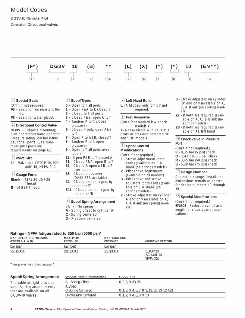
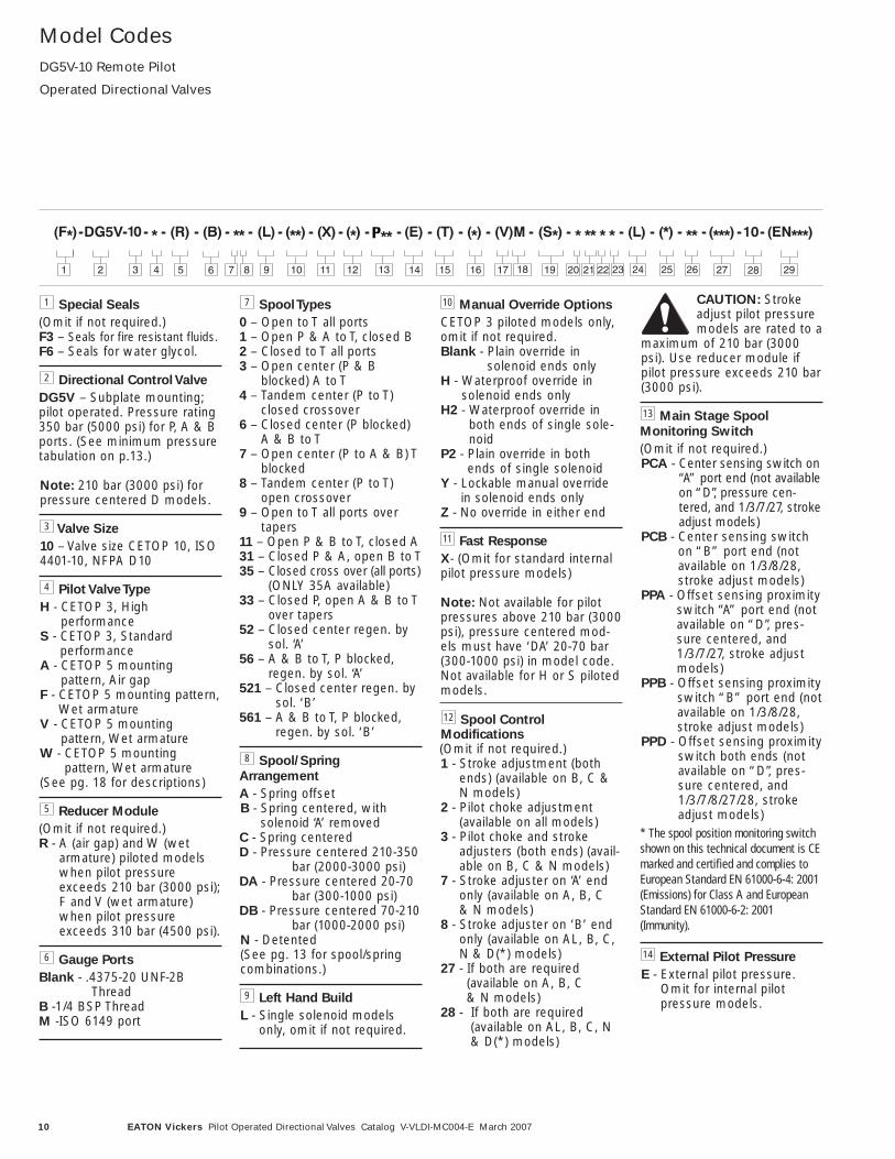
Model CodesDG3V-10 Remote Pilot
Operated Directional Valves
Special Seals
(Omit if not required.)F3 – Seals for fire resistant flu-
ids.F6 – Seals for water glycol.
Directional Control Valve
DG3V – Subplate mounting;pilot operated-remote operator.Pressure rating 350 bar (5000psi) for all ports. (See mini-mum pilot pressurerequirements on page 6.)
Valve Size
10 – Valve size CETOP 10, ISO4401-10, NFPA D10
Gauge Ports
Blank - .4375-20 UNF-2BThread
B -1/4 BSP Thread
Spool Types
0 – Open to T all ports1 – Open P&A to T, closed B2 – Closed to T all ports3 – Closed P&B, open A to T4 – Tandem P to T, closed
crossover6 – Closed P only, open A&B
to T7 – Open P to A&B, closed T8 – Tandem P to T, open
crossover9 – Open to T all ports over
tapers11 – Open P&B to T, closed A31 – Closed P&A, open B to T33 – Closed P, open A&B to T
over tapers35 – Closed cross over
(ONLY 35A available)52 – Closed center, regen. by
operator ‘A’521 – Closed center, regen. by
operator ‘B’
Spool Spring Arrangement
Blank - No springA - Spring offset to cylinder ‘A’C - Spring centeredD - Pressure centered
Left Hand Build
L - A Models only, omit if notrequired.
Fast Response
(Omit for standard low shockmodels.)
X- Not available with CETOP 3pilots or pressure centered ‘D’and ‘DB’ models.
Spool Control
Modifications
(Omit if not required.)1 - Stroke adjustment (both
ends) (available on C &Blank (no spring) models)
2 - Pilot choke adjustment(available on all models)
3 - Pilot choke and strokeadjusters (both ends) (avail-able on C & Blank (nospring) models)
7 - Stroke adjusters on cylinderA end only (available on A,C & Blank (no spring) mod-els)
8 - Stroke adjusters on cylinder‘B’ end only (available on A,C, & Blank (no spring) mod-els)
27 - If both are required (avail-able on A, C, & Blank (nospring) models)
28 - If both are required (avail-able on AL left hand
Check Valve in Pressure
Port
(Omit if not required.)K - 0,35 bar (5 psi) checkQ - 2,42 bar (35 psi) checkR - 3,45 bar (50 psi) checkS - 5,20 bar (75 psi) check
Design Number
Subject to change. Installationdimensions remain as shownfor design numbers 10 through19.
Special Modifications
(Omit if not required.)EN503 - Reduced overall axiallength for close quarter appli-cations.
12
11
10
9
8
7
6
5
4
3
2
1
(F*) DG3V 10 (B) ** (L) (X) (*) (*) 10 (EN**)
1 7 122 3 4 5 6 8 9 10 11
Ratings - NFPA fatigue rated to 350 bar (5000 psi)*MAX. OPERATING PRESSURE MAX. PILOT MAX. TANK LINE (PORTS P, A, & B) PRESSURE PRESSURE MOUNTING PATTERN
bar (psi) bar (psi) bar (psi)350 (5000) 210 (3000) 210 (3000) CETOP 10
ISO 4401-10NFPA D10
* See power limits chart on page 7.
Spool/Spring Arrangement
The table at right providesspool/spring arrangementsthat are available on allDG3V-10 valves.
SPOOL/SPRING ARRANGEMENT SPOOL TYPE
A - Spring Offset 0, 2, 6, 9, 33, 35BLANKC-Spring Centered 0, 1, 2, 3, 4, 6, 7, 8, 9, 11, 31, 33, 52, 521D-Pressure Centered 0, 1, 2, 3, 4, 6, 8, 9, 33
5EATON Vickers Pilot Operated Directional Valves Catalog V-VLDI-MC004-E March 2007
ModelDescription/PerformanceCharacteristics
Model Description
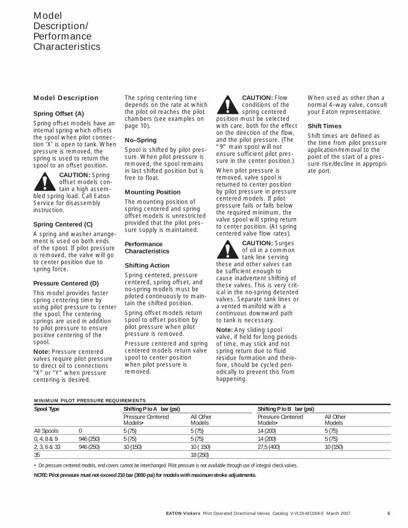
Spring Offset (A)
Spring offset models have aninternal spring which offsetsthe spool when pilot connec-tion ‘X’ is open to tank. Whenpressure is removed, thespring is used to return thespool to an offset position.
CAUTION: Springoffset models con-tain a high assem-
bled spring load. Call EatonService for disassemblyinstruction.
Spring Centered (C)
A spring and washer arrange-ment is used on both endsof the spool. If pilot pressureis removed, the valve will goto center position due tospring force.
Pressure Centered (D)
This model provides fasterspring centering time byusing pilot pressure to centerthe spool. The centeringsprings are used in additionto pilot pressure to ensurepositive centering of thespool.
Note: Pressure centeredvalves require pilot pressureto direct oil to connections‘‘X’’ or ‘‘Y’’ when pressurecentering is desired.
The spring centering timedepends on the rate at whichthe pilot oil reaches the pilotchambers (see examples onpage 10).
No–Spring
Spool is shifted by pilot pres-sure. When pilot pressure isremoved, the spool remainsin last shifted position but isfree to float.
Mounting Position
The mounting position ofspring centered and springoffset models is unrestrictedprovided that the pilot pres-sure supply is maintained.
PerformanceCharacteristics
Shifting Action
Spring centered, pressurecentered, spring offset, andno-spring models must bepiloted continuously to main-tain the shifted position.
Spring offset models returnspool to offset position bypilot pressure when pilotpressure is removed.
Pressure centered and springcentered models return valvespool to center positionwhen pilot pressure isremoved.
CAUTION: Flowconditions of thespring centered
position must be selectedwith care, both for the effecton the direction of the flow,and the pilot pressure. (The“9” main spool will notensure sufficient pilot pres-sure in the center position.)
When pilot pressure isremoved, valve spool isreturned to center positionby pilot pressure in pressurecentered models. If pilotpressure fails or falls belowthe required minimum, thevalve spool will spring returnto center position. (At springcentered valve flow rates).
CAUTION: Surgesof oil in a commontank line serving
these and other valves canbe sufficient enough tocause inadvertent shifting ofthese valves. This is very crit-ical in the no-spring detentedvalves. Separate tank lines ora vented manifold with acontinuous downward pathto tank is necessary.
Note: Any sliding spoolvalve, if held for long periodsof time, may stick and notspring return due to fluidresidue formation and there-fore, should be cycled peri-odically to prevent this fromhappening.
When used as other than anormal 4–way valve, consultyour Eaton representative.
Shift Times
Shift times are defined asthe time from pilot pressureapplication/removal to thepoint of the start of a pres-sure rise/decline in appropri-ate port.
MINIMUM PILOT PRESSURE REQUIREMENTS
Spool Type Shifting P to A bar (psi) Shifting P to B bar (psi)Pressure Centered All Other Pressure Centered All Other Models• Models Models• Models
All Spools 0 5 (75) 5 (75) 14 (200) 5 (75)0, 4, 8 & 9 946 (250) 5 (75) 5 (75) 14 (200) 5 (75)2, 3, 6 & 33 946 (250) 10 (150) 10 ( 150) 27,5 (400) 10 (150)35 18 (250)
• On pressure centered models, end covers cannot be interchanged. Pilot pressure is not available through use of integral check valves.
NOTE: Pilot pressure must not exceed 210 bar (3000 psi) for models with maximum stroke adjustments.
6 EATON Vickers Pilot Operated Directional Valves Catalog V-VLDI-MC004-E March 2007
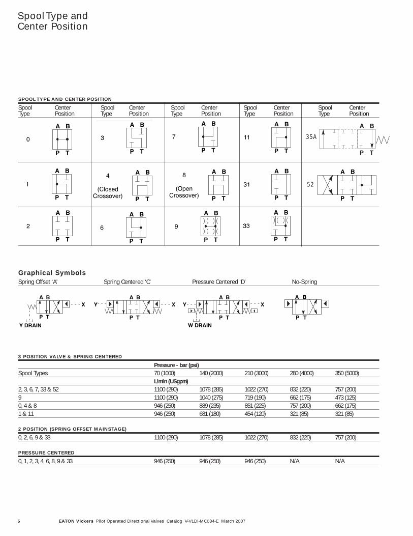
SPOOL TYPE AND CENTER POSITION
Spool Center Spool Center Spool Center Spool Center Spool CenterType Position Type Position Type Position Type Position Type Position
Spool Type andCenter Position
Graphical SymbolsSpring Offset ‘A’ Spring Centered ‘C’ Pressure Centered ‘D’ No-Spring
A B
P T
A B
P T
A B
P TW DRAIN
A B
P TY DRAIN
XY Y XX
3 POSITION VALVE & SPRING CENTERED
Pressure - bar (psi)Spool Types 70 (1000) 140 (2000) 210 (3000) 280 (4000) 350 (5000)
L/min (USgpm)2, 3, 6, 7, 33 & 52 1100 (290) 1078 (285) 1022 (270) 832 (220) 757 (200)9 1100 (290) 1040 (275) 719 (190) 662 (175) 473 (125)0, 4 & 8 946 (250) 889 (235) 851 (225) 757 (200) 662 (175)1 & 11 946 (250) 681 (180) 454 (120) 321 (85) 321 (85)
2 POSITION (SPRING OFFSET MAINSTAGE)
0, 2, 6, 9 & 33 1100 (290) 1078 (285) 1022 (270) 832 (220) 757 (200)
PRESSURE CENTERED
0, 1, 2, 3, 4, 6, 8, 9 & 33 946 (250) 946 (250) 946 (250) N/A N/A
A B
P T
0
A B
P T
3 7
A B
P T
11
A B
P T
A B
P T
A B
P T
14
(ClosedCrossover)
A B
P T
A B
P T
8
(OpenCrossover)
A B
P T
31
A B
P T
2
A B
P T
6 9
A B
P T
A B
P T
33
52
35A
A B
P T
7EATON Vickers Pilot Operated Directional Valves Catalog V-VLDI-MC004-E March 2007
Pressure Drop
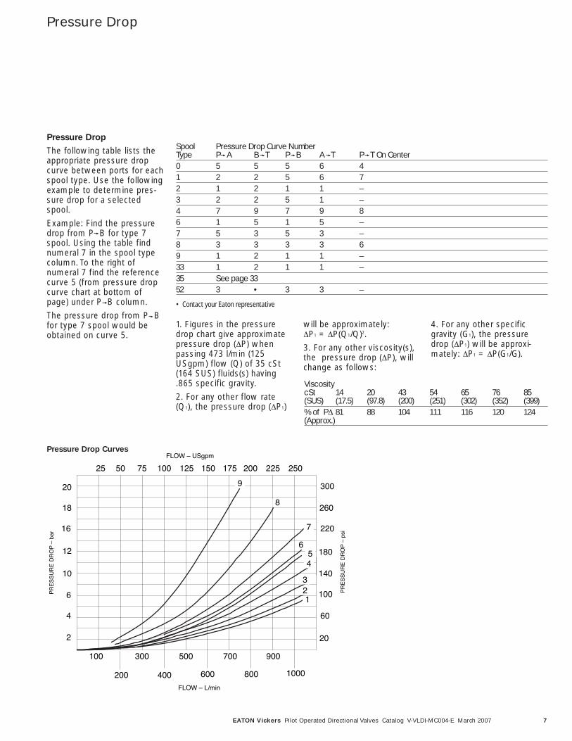
Pressure Drop
The following table lists theappropriate pressure dropcurve between ports for eachspool type. Use the followingexample to determine pres-sure drop for a selectedspool.
Example: Find the pressuredrop from P B for type 7spool. Using the table findnumeral 7 in the spool typecolumn. To the right ofnumeral 7 find the referencecurve 5 (from pressure dropcurve chart at bottom ofpage) under P B column.
The pressure drop from P Bfor type 7 spool would beobtained on curve 5.
Spool Pressure Drop Curve Number Type P A B T P B A T P T On Center0 5 5 5 6 41 2 2 5 6 72 1 2 1 1 –3 2 2 5 1 –4 7 9 7 9 86 1 5 1 5 –7 5 3 5 3 –8 3 3 3 3 69 1 2 1 1 –33 1 2 1 1 –35 See page 3352 3 • 3 3 –
• Contact your Eaton representative
1. Figures in the pressuredrop chart give approximatepressure drop (ΔP) whenpassing 473 l/min (125USgpm) flow (Q) of 35 cSt(164 SUS) fluids(s) having.865 specific gravity.
2. For any other flow rate(Q1), the pressure drop (ΔP1)
will be approximately: ΔP1 = ΔP(Q1/Q)2.
3. For any other viscosity(s),the pressure drop (ΔP), willchange as follows:
4. For any other specificgravity (G1), the pressuredrop (ΔP1) will be approxi-mately: ΔP1 = ΔP(G1/G).
ViscositycSt 14 20 43 54 65 76 85(SUS) (17.5) (97.8) (200) (251) (302) (352) (399)% of PΔ 81 88 104 111 116 120 124(Approx.)
Pressure Drop CurvesFLOW – USgpm
FLOW – L/min
8
7
654
321
9
25 50 75 100 125 150 175 200 225 250
100
200
300
400
500
600
700
800
900
1000
300
260
220
180
140
100
60
20
20
18
16
12
10
6
4
2
P
OR
D E
RU
SS
ER
P–
rab
P
OR
D E
RU
SS
ER
P–
isp
3V-10 Spring Centered &ring Offset Models
3V-10 Pressure Centered Models
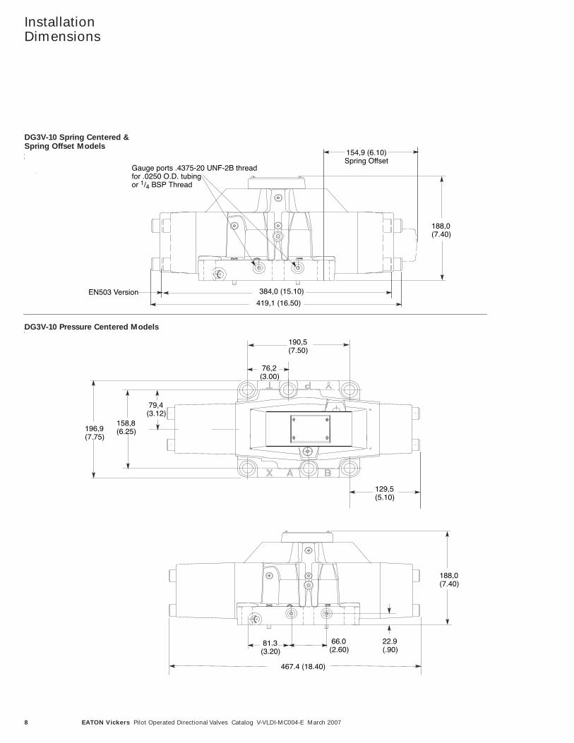
188,0(7.40)
154,9 (6.10)Spring Offset
384,0 (15.10)
Gauge ports .4375-20 UNF-2B threadfor .0250 O.D. tubingor 1/4 BSP Thread
419,1 (16.50)
EN503 Version
188,0(7.40)
190,5(7.50)
158,8(6.25)
79,4(3.12)
129,5(5.10)
467.4 (18.40)
76,2 (3.00)
196,9(7.75)
81.3(3.20)
22.9(.90)
66.0(2.60)
8 EATON Vickers Pilot Operated Directional Valves Catalog V-VLDI-MC004-E March 2007
InstallationDimensions
DG3V-10 Spring Centered &Spring Offset Models
DG3V-10 Pressure Centered Models
9EATON Vickers Pilot Operated Directional Valves Catalog V-VLDI-MC004-E March 2007
Optional Features
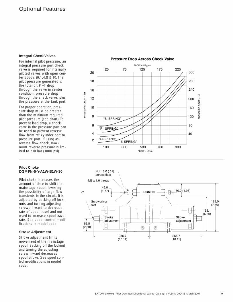
Integral Check Valves
For internal pilot pressure, anintegral pressure port checkvalve is required for internallypiloted valves with open cen-ter spools (0,1,4,8 & 9). Thepilot pressure generated isthe total of: P T dropthrough the valve in centercondition, pressure dropthrough the check valve, plusthe pressure at the tank port.
For proper operation, pres-sure drop must be greaterthan the minimum requiredpilot pressure (see chart). Toprevent load drop, a checkvalve in the pressure port canbe used to prevent reverseflow from ‘‘A’’ cylinder port topressure port. If using asreverse flow check, maxi-mum reverse pressure is lim-ited to 210 bar (3000 psi)
Pilot Choke DGMFN-5-Y-A1W-B1W-30
Pilot choke increases theamount of time to shift themainstage spool, loweringthe possibility of large flowtransients in the circuit. It isadjusted by backing off lock-nuts and turning adjustingscrews inward to decreaserate of spool travel and out-ward to increase spool travelrate. See spool control modi-fications in model code.
Stroke Adjustment
Stroke adjustment limitsmovement of the mainstagespool. Backing off the locknutand turning the adjustingscrew inward decreasesspool stroke. See spool con-trol modifications in modelcode.
ʻʻS SPRINGʼʼ
ʻʻR SPRINGʼʼ
ʻʻK SPRINGʼʼ
100 300 500 700 900
20
18
16
12
10
6
2
P
OR
D E
RU
SS
ER
P–
rab
P
OR
D E
RU
SS
ER
P–
is p
25 75 125 175 225
40
80
120
160
200
240
280
300
FLOW – L/min
FLOW – USgpm
Pressure Drop Across Check Valve
ʻʻQ SPRINGʼʼ
4
8
by
w
45,0(1.77)
Screwdriverslot
M8 x 1.0 thread
Nut 13,0 (.51) across flats
256,7(10.11)
256,7(10.11)
63,5(2.50)
Strokeadjustment
Strokeadjustment
DGMFN
165,1(6.50)
50,0 (1.96)
188,0(7.40)
10 EATON Vickers Pilot Operated Directional Valves Catalog V-VLDI-MC004-E March 2007
Model CodesDG5V-10 Remote Pilot
Operated Directional Valves
Special Seals
(Omit if not required.)F3 – Seals for fire resistant fluids.F6 – Seals for water glycol.
Directional Control Valve
DG5V – Subplate mounting;pilot operated. Pressure rating350 bar (5000 psi) for P, A & Bports. (See minimum pressuretabulation on p.13.)
Note: 210 bar (3000 psi) forpressure centered D models.
Valve Size
10 – Valve size CETOP 10, ISO4401-10, NFPA D10
Pilot Valve Type
H - CETOP 3, High performance
S - CETOP 3, Standard performance
A - CETOP 5 mounting pattern, Air gap
F - CETOP 5 mounting pattern,Wet armature
V - CETOP 5 mounting pattern, Wet armature
W - CETOP 5 mounting pattern, Wet armature
(See pg. 18 for descriptions)
Reducer Module
(Omit if not required.)R - A (air gap) and W (wet
armature) piloted modelswhen pilot pressureexceeds 210 bar (3000 psi);F and V (wet armature)when pilot pressureexceeds 310 bar (4500 psi).
Gauge Ports
Blank - .4375-20 UNF-2BThread
B -1/4 BSP ThreadM -ISO 6149 port
Spool Types
0 – Open to T all ports1 – Open P & A to T, closed B2 – Closed to T all ports3 – Open center (P & B
blocked) A to T4 – Tandem center (P to T)
closed crossover6 – Closed center (P blocked)
A & B to T7 – Open center (P to A & B) T
blocked8 – Tandem center (P to T)
open crossover9 – Open to T all ports over
tapers11 – Open P & B to T, closed A31 – Closed P & A, open B to T35 – Closed cross over (all ports)
(ONLY 35A available)33 – Closed P, open A & B to T
over tapers52 – Closed center regen. by
sol. ‘A’56 – A & B to T, P blocked,
regen. by sol. ‘A’521 – Closed center regen. by
sol. ‘B’561 – A & B to T, P blocked,
regen. by sol. ‘B’
Spool/Spring
Arrangement
A - Spring offset B - Spring centered, with
solenoid ‘A’ removedC - Spring centeredD - Pressure centered 210-350
bar (2000-3000 psi)DA - Pressure centered 20-70
bar (300-1000 psi)DB - Pressure centered 70-210
bar (1000-2000 psi)N - Detented (See pg. 13 for spool/springcombinations.)
Left Hand Build
L - Single solenoid modelsonly, omit if not required.
Manual Override Options
CETOP 3 piloted models only,omit if not required.Blank - Plain override in
solenoid ends onlyH - Waterproof override in
solenoid ends onlyH2 - Waterproof override in
both ends of single sole-noid
P2 - Plain override in bothends of single solenoid
Y - Lockable manual overridein solenoid ends only
Z - No override in either end
Fast Response
X- (Omit for standard internalpilot pressure models)
Note: Not available for pilotpressures above 210 bar (3000psi), pressure centered mod-els must have ‘DA’ 20-70 bar(300-1000 psi) in model code.Not available for H or S pilotedmodels.
Spool ControlModifications(Omit if not required.)1 - Stroke adjustment (both
ends) (available on B, C &N models)
2 - Pilot choke adjustment(available on all models)
3 - Pilot choke and strokeadjusters (both ends) (avail-able on B, C & N models)
7 - Stroke adjuster on ‘A’ endonly (available on A, B, C & N models)
8 - Stroke adjuster on ‘B’ endonly (available on AL, B, C,N & D(*) models)
27 - If both are required (available on A, B, C & N models)
28 - If both are required (available on AL, B, C, N& D(*) models)
CAUTION: Strokeadjust pilot pressuremodels are rated to a
maximum of 210 bar (3000psi). Use reducer module ifpilot pressure exceeds 210 bar(3000 psi).
Main Stage Spool
Monitoring Switch
(Omit if not required.)PCA - Center sensing switch on
“A” port end (not availableon “D”, pressure cen-tered, and 1/3/7/27, strokeadjust models)
PCB - Center sensing switchon “B” port end (notavailable on 1/3/8/28,stroke adjust models)
PPA - Offset sensing proximityswitch “A” port end (notavailable on “D”, pres-sure centered, and1/3/7/27, stroke adjustmodels)
PPB - Offset sensing proximityswitch “B” port end (notavailable on 1/3/8/28,stroke adjust models)
PPD - Offset sensing proximityswitch both ends (notavailable on “D”, pres-sure centered, and1/3/7/8/27/28, strokeadjust models)
* The spool position monitoring switchshown on this technical document is CEmarked and certified and complies toEuropean Standard EN 61000-6-4: 2001(Emissions) for Class A and EuropeanStandard EN 61000-6-2: 2001(Immunity).
External Pilot Pressure
E - External pilot pressure.Omit for internal pilot pressure models.
13
14
10
6
5
12
11
9
8
7
4
3
2
1
P
2 3 4 7 5 8 1 10 11 12 14 15 16 17 18 19 20 9 2721 22 23 24 25 26 286 2913
P P
11EATON Vickers Pilot Operated Directional Valves Catalog V-VLDI-MC004-E March 2007
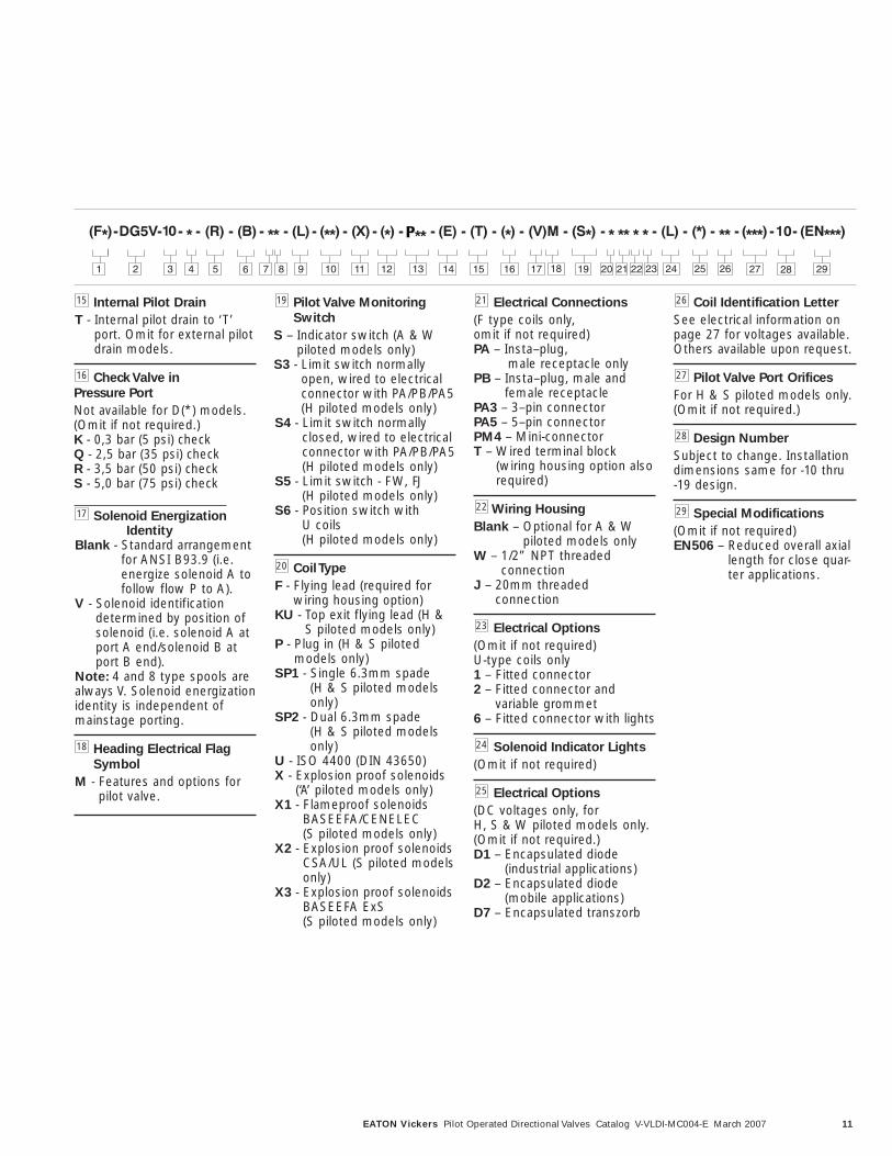
Internal Pilot Drain
T - Internal pilot drain to ‘T’port. Omit for external pilotdrain models.
Check Valve in
Pressure Port
Not available for D(*) models.(Omit if not required.)K - 0,3 bar (5 psi) checkQ - 2,5 bar (35 psi) checkR - 3,5 bar (50 psi) checkS - 5,0 bar (75 psi) check
Solenoid EnergizationIdentity
Blank - Standard arrangementfor ANSI B93.9 (i.e.energize solenoid A tofollow flow P to A).
V - Solenoid identificationdetermined by position ofsolenoid (i.e. solenoid A atport A end/solenoid B atport B end).
Note: 4 and 8 type spools arealways V. Solenoid energizationidentity is independent ofmainstage porting.
Heading Electrical Flag
Symbol
M - Features and options forpilot valve.
Pilot Valve Monitoring
Switch
S – Indicator switch (A & Wpiloted models only)
S3 - Limit switch normallyopen, wired to electricalconnector with PA/PB/PA5 (H piloted models only)
S4 - Limit switch normallyclosed, wired to electricalconnector with PA/PB/PA5 (H piloted models only)
S5 - Limit switch - FW, FJ (H piloted models only)
S6 - Position switch with U coils (H piloted models only)
Coil Type
F - Flying lead (required forwiring housing option)
KU - Top exit flying lead (H &S piloted models only)
P - Plug in (H & S piloted models only)
SP1 - Single 6.3mm spade(H & S piloted modelsonly)
SP2 - Dual 6.3mm spade(H & S piloted modelsonly)
U - ISO 4400 (DIN 43650)X - Explosion proof solenoids
(‘A’ piloted models only)X1 - Flameproof solenoids
BASEEFA/CENELEC (S piloted models only)
X2 - Explosion proof solenoidsCSA/UL (S piloted modelsonly)
X3 - Explosion proof solenoidsBASEEFA ExS (S piloted models only)
Electrical Connections
(F type coils only, omit if not required)PA – Insta–plug,
male receptacle onlyPB – Insta–plug, male and
female receptaclePA3 – 3–pin connectorPA5 – 5–pin connectorPM4 – Mini-connectorT – Wired terminal block
(wiring housing option alsorequired)
Wiring Housing
Blank – Optional for A & Wpiloted models only
W – 1/2” NPT threaded connection
J – 20mm threaded connection
Electrical Options
(Omit if not required)U-type coils only1 – Fitted connector2 – Fitted connector and
variable grommet6 – Fitted connector with lights
Solenoid Indicator Lights
(Omit if not required)
Electrical Options
(DC voltages only, for H, S & W piloted models only.(Omit if not required.)D1 – Encapsulated diode
(industrial applications)D2 – Encapsulated diode
(mobile applications)D7 – Encapsulated transzorb
Coil Identification Letter
See electrical information onpage 27 for voltages available.Others available upon request.
Pilot Valve Port Orifices
For H & S piloted models only.(Omit if not required.)
Design Number
Subject to change. Installationdimensions same for -10 thru -19 design.
Special Modifications
(Omit if not required)EN506 – Reduced overall axial
length for close quar-ter applications.
16
15 19
18
17
20
29
28
27
26
25
24
23
21
22
P
2 3 4 7 5 8 1 10 11 12 14 15 16 17 18 19 20 9 2721 22 23 24 25 26 286 2913
P P
12 EATON Vickers Pilot Operated Directional Valves Catalog V-VLDI-MC004-E March 2007
Ratings/ModelDescription
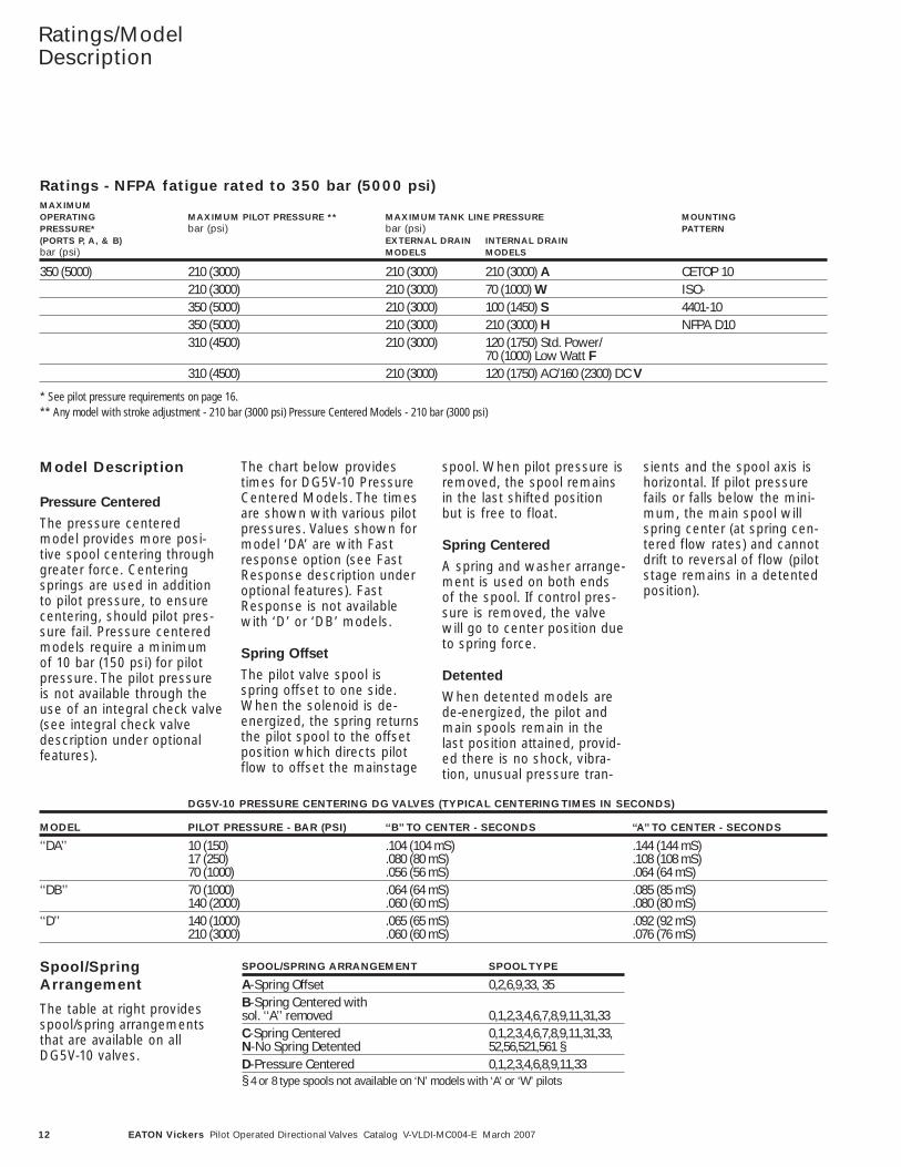
Ratings - NFPA fatigue rated to 350 bar (5000 psi)MAXIMUMOPERATING MAXIMUM PILOT PRESSURE ** MAXIMUM TANK LINE PRESSURE MOUNTINGPRESSURE* bar (psi) bar (psi) PATTERN(PORTS P, A, & B) EXTERNAL DRAIN INTERNAL DRAINbar (psi) MODELS MODELS
350 (5000) 210 (3000) 210 (3000) 210 (3000) A CETOP 10210 (3000) 210 (3000) 70 (1000) W ISO-350 (5000) 210 (3000) 100 (1450) S 4401-10350 (5000) 210 (3000) 210 (3000) H NFPA D10310 (4500) 210 (3000) 120 (1750) Std. Power/
70 (1000) Low Watt F310 (4500) 210 (3000) 120 (1750) AC/160 (2300) DC V
* See pilot pressure requirements on page 16. ** Any model with stroke adjustment - 210 bar (3000 psi) Pressure Centered Models - 210 bar (3000 psi)
DG5V-10 PRESSURE CENTERING DG VALVES (TYPICAL CENTERING TIMES IN SECONDS)
MODEL PILOT PRESSURE - BAR (PSI) ‘‘B’’ TO CENTER - SECONDS ‘‘A’’ TO CENTER - SECONDS
‘‘DA’’ 10 (150) .104 (104 mS) .144 (144 mS)17 (250) .080 (80 mS) .108 (108 mS)70 (1000) .056 (56 mS) .064 (64 mS)
‘‘DB’’ 70 (1000) .064 (64 mS) .085 (85 mS)140 (2000) .060 (60 mS) .080 (80 mS)
‘‘D’’ 140 (1000) .065 (65 mS) .092 (92 mS)210 (3000) .060 (60 mS) .076 (76 mS)
SPOOL/SPRING ARRANGEMENT SPOOL TYPE
A-Spring Offset 0,2,6,9,33, 35B-Spring Centered withsol. ‘‘A’’ removed 0,1,2,3,4,6,7,8,9,11,31,33C-Spring Centered 0,1,2,3,4,6,7,8,9,11,31,33,N-No Spring Detented 52,56,521,561 §D-Pressure Centered 0,1,2,3,4,6,8,9,11,33§ 4 or 8 type spools not available on ‘N’ models with ‘A’ or ‘W’ pilots
Model Description
Pressure Centered
The pressure centeredmodel provides more posi-tive spool centering throughgreater force. Centeringsprings are used in additionto pilot pressure, to ensurecentering, should pilot pres-sure fail. Pressure centeredmodels require a minimumof 10 bar (150 psi) for pilotpressure. The pilot pressureis not available through theuse of an integral check valve(see integral check valvedescription under optionalfeatures).
The chart below providestimes for DG5V-10 PressureCentered Models. The timesare shown with various pilotpressures. Values shown formodel ‘DA’ are with Fastresponse option (see FastResponse description underoptional features). FastResponse is not availablewith ‘D’ or ‘DB’ models.
Spring Offset
The pilot valve spool isspring offset to one side.When the solenoid is de-energized, the spring returnsthe pilot spool to the offsetposition which directs pilotflow to offset the mainstage
spool. When pilot pressure isremoved, the spool remainsin the last shifted positionbut is free to float.
Spring Centered
A spring and washer arrange-ment is used on both endsof the spool. If control pres-sure is removed, the valvewill go to center position dueto spring force.
Detented
When detented models arede-energized, the pilot andmain spools remain in thelast position attained, provid-ed there is no shock, vibra-tion, unusual pressure tran-
sients and the spool axis ishorizontal. If pilot pressurefails or falls below the mini-mum, the main spool willspring center (at spring cen-tered flow rates) and cannotdrift to reversal of flow (pilotstage remains in a detentedposition).
Spool/SpringArrangement
The table at right providesspool/spring arrangementsthat are available on allDG5V-10 valves.
13EATON Vickers Pilot Operated Directional Valves Catalog V-VLDI-MC004-E March 2007
Power Limits/PerformanceCharacteristics
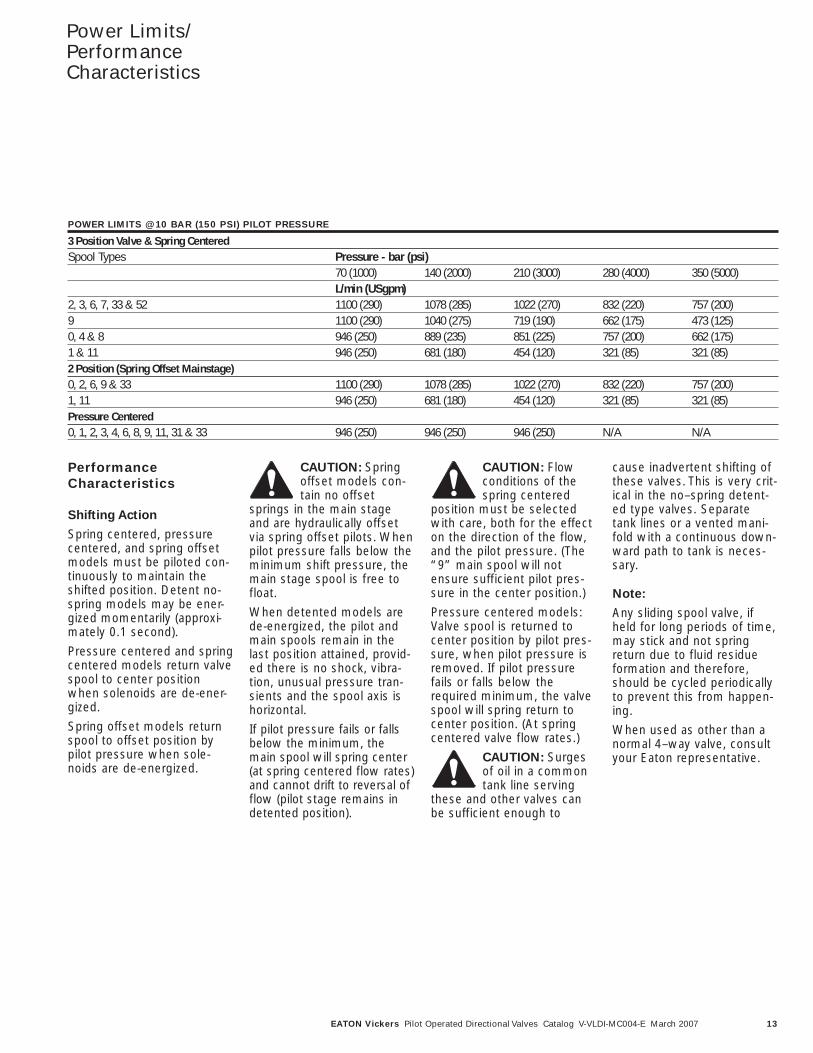
PerformanceCharacteristics
Shifting Action
Spring centered, pressurecentered, and spring offsetmodels must be piloted con-tinuously to maintain theshifted position. Detent no-spring models may be ener-gized momentarily (approxi-mately 0.1 second).
Pressure centered and springcentered models return valvespool to center positionwhen solenoids are de-ener-gized.
Spring offset models returnspool to offset position bypilot pressure when sole-noids are de-energized.
CAUTION: Springoffset models con-tain no offset
springs in the main stageand are hydraulically offsetvia spring offset pilots. Whenpilot pressure falls below theminimum shift pressure, themain stage spool is free tofloat.
When detented models arede-energized, the pilot andmain spools remain in thelast position attained, provid-ed there is no shock, vibra-tion, unusual pressure tran-sients and the spool axis ishorizontal.
If pilot pressure fails or fallsbelow the minimum, themain spool will spring center(at spring centered flow rates)and cannot drift to reversal offlow (pilot stage remains indetented position).
CAUTION: Flowconditions of thespring centered
position must be selectedwith care, both for the effecton the direction of the flow,and the pilot pressure. (The“9” main spool will notensure sufficient pilot pres-sure in the center position.)
Pressure centered models:Valve spool is returned tocenter position by pilot pres-sure, when pilot pressure isremoved. If pilot pressurefails or falls below therequired minimum, the valvespool will spring return tocenter position. (At springcentered valve flow rates.)
CAUTION: Surgesof oil in a commontank line serving
these and other valves canbe sufficient enough to
cause inadvertent shifting ofthese valves. This is very crit-ical in the no–spring detent-ed type valves. Separatetank lines or a vented mani-fold with a continuous down-ward path to tank is neces-sary.
Note:
Any sliding spool valve, ifheld for long periods of time,may stick and not springreturn due to fluid residueformation and therefore,should be cycled periodicallyto prevent this from happen-ing.
When used as other than anormal 4–way valve, consultyour Eaton representative.
POWER LIMITS @ 10 BAR (150 PSI) PILOT PRESSURE
3 Position Valve & Spring CenteredSpool Types Pressure - bar (psi)
70 (1000) 140 (2000) 210 (3000) 280 (4000) 350 (5000)L/min (USgpm)
2, 3, 6, 7, 33 & 52 1100 (290) 1078 (285) 1022 (270) 832 (220) 757 (200)9 1100 (290) 1040 (275) 719 (190) 662 (175) 473 (125)0, 4 & 8 946 (250) 889 (235) 851 (225) 757 (200) 662 (175)1 & 11 946 (250) 681 (180) 454 (120) 321 (85) 321 (85)2 Position (Spring Offset Mainstage)0, 2, 6, 9 & 33 1100 (290) 1078 (285) 1022 (270) 832 (220) 757 (200)1, 11 946 (250) 681 (180) 454 (120) 321 (85) 321 (85)Pressure Centered0, 1, 2, 3, 4, 6, 8, 9, 11, 31 & 33 946 (250) 946 (250) 946 (250) N/A N/A
14 EATON Vickers Pilot Operated Directional Valves Catalog V-VLDI-MC004-E March 2007
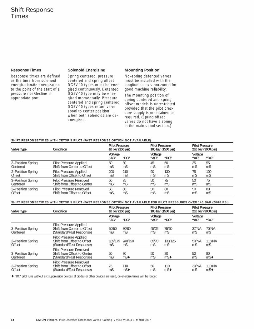
Response Times
Response times are definedas the time from solenoidenergization/de-energizationto the point of the start of apressure rise/decline inappropriate port.
Solenoid Energizing
Spring centered, pressurecentered and spring offsetDG5V-10 types must be ener-gized continuously. DetentedDG5V-10 type may be ener-gized momentarily. Pressurecentered and spring centeredDG5V-10 types return valvespool to center positionwhen both solenoids are de-energized.
Mounting Position
No–spring detented valvesmust be installed with thelongitudinal axis horizontal forgood machine reliability.
The mounting position ofspring centered and springoffset models is unrestrictedprovided that the pilot pres-sure supply is maintained asrequired. (Spring offsetvalves do not have a springin the main spool section.)
Shift ResponseTimes
SHIFT RESPONSE TIMES WITH CETOP 3 PILOT (FAST RESPONSE OPTION NOT AVAILABLE)
Pilot Pressure Pilot Pressure Pilot PressureValve Type Condition 10 bar (150 psi) 100 bar (1500 psi) 210 bar (3000 psi)
Voltage Voltage Voltage‘‘AC’’ ‘‘DC’’ ‘‘AC’’ ‘‘DC’’ ‘‘AC’’ ‘‘DC’’
3–Position Spring Pilot Pressure Applied 50 80 45 60 35 55Centered Shift from Center to Offset mS mS mS mS mS mS2–Position Spring Pilot Pressure Applied 200 210 90 130 75 100Offset Shift from Offset to Offset mS mS mS mS mS mS3–Position Spring Pilot Pressure Removed 50 75 50 75 50 75Centered Shift from Offset to Center mS mS mS mS mS mS2–Position Spring Pilot Pressure Removed 50 80 50 80 50 80Offset Shift from Offset to Offset mS mS mS mS mS mS
SHIFT RESPONSE TIMES WITH CETOP 5 PILOT (FAST RESPONSE OPTION NOT AVAILABLE FOR PILOT PRESSURES OVER 140 BAR (2000 PSI)
Pilot Pressure Pilot Pressure Pilot PressureValve Type Condition 10 bar (150 psi) 100 bar (1500 psi) 210 bar (3000 psi)
Voltage Voltage Voltage‘‘AC’’ ‘‘DC’’ ‘‘AC’’ ‘‘DC’’ ‘‘AC’’ ‘‘DC’’
Pilot Pressure Applied3–Position Spring Shift from Center to Offset 50/50 80/80 45/25 75/60 37/NA 70/NACentered (Standard/Fast Response) mS mS mS mS mS mS
Pilot Pressure Applied2–Position Spring Shift from Offset to Offset 185/175 240/190 85/70 130/125 50/NA 115/NAOffset (Standard/Fast Response) mS mS mS mS mS mS
Pilot Pressure Removed3–Position Spring Shift from Offset to Center 50 80 50 80 50 80Centered (Standard/Fast Response) mS mS♦ mS mS♦ mS mS♦
Pilot Pressure Removed2–Position Spring Shift from Offset to Offset 75 110 50 110 30/NA 110/NAOffset (Standard/Fast Response) mS mS♦ mS mS♦ mS mS♦
♦ “DC” pilot runs without arc suppression devices. If diodes or other devices are used, de-energize times will be longer.
SPOOL TYPE AND CENTER POSITION
Spool Center Spool Center Spool Center Spool Center Spool CenterType Position Type Position Type Position Type Position Type Position
15EATON Vickers Pilot Operated Directional Valves Catalog V-VLDI-MC004-E March 2007
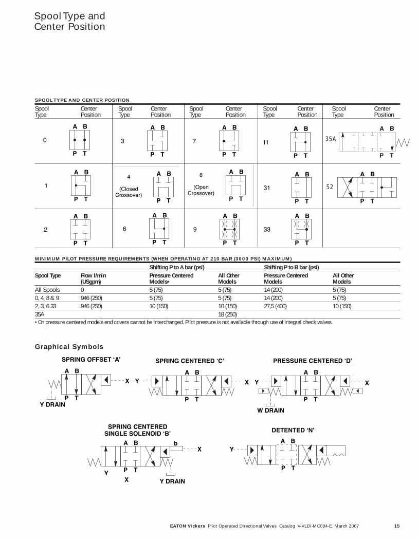
Spool Type andCenter Position
A B
P T
0
MINIMUM PILOT PRESSURE REQUIREMENTS (WHEN OPERATING AT 210 BAR (3000 PSI) MAXIMUM)
Shifting P to A bar (psi) Shifting P to B bar (psi)Spool Type Flow l/min Pressure Centered All Other Pressure Centered All Other
(USgpm) Models• Models Models ModelsAll Spools 0 5 (75) 5 (75) 14 (200) 5 (75)0, 4, 8 & 9 946 (250) 5 (75) 5 (75) 14 (200) 5 (75)2, 3, 6 33 946 (250) 10 (150) 10 (150) 27,5 (400) 10 (150)35A 18 (250)• On pressure centered models end covers cannot be interchanged. Pilot pressure is not available through use of integral check valves.
A B
P T
3 7
A B
P T
11
A B
P T
A B
P T
1
4
(ClosedCrossover)
A B
P T
A B
P T
8
(OpenCrossover)
A B
P T
31
A B
P T
2
A B
P T
6 9
A B
P T
A B
P T
33
Graphical Symbols
A B
P T
SPRING OFFSET ʻAʼ
A B
P T
SPRING CENTERED ʻCʼ
A B
P T
PRESSURE CENTERED ʻDʼ
W DRAIN
A B
P T
DETENTED ʻNʼ
A B
P T
b
SPRING CENTEREDSINGLE SOLENOID ʻBʼ
Y DRAIN
Y DRAIN
XY
X XY X Y
X Y
A B
P T
52
35A
A B
P T
16 EATON Vickers Pilot Operated Directional Valves Catalog V-VLDI-MC004-E March 2007
Pressure Drop
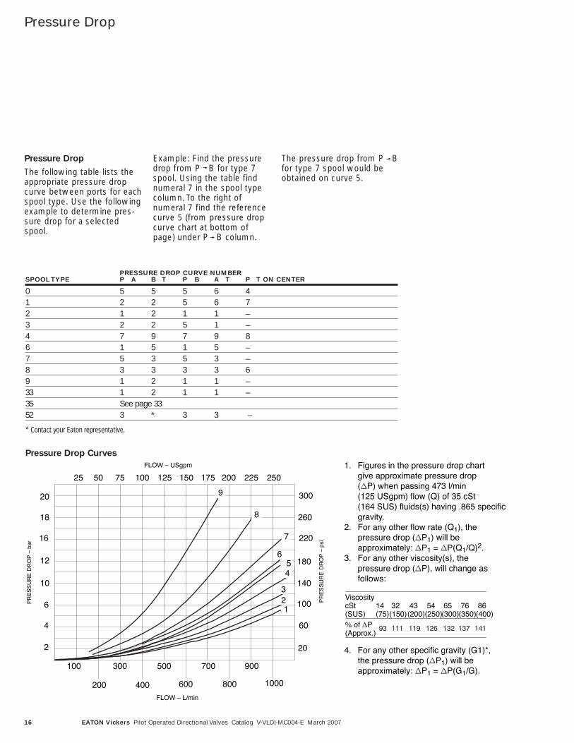
Pressure Drop
The following table lists theappropriate pressure dropcurve between ports for eachspool type. Use the followingexample to determine pres-sure drop for a selectedspool.
Example: Find the pressuredrop from P B for type 7spool. Using the table findnumeral 7 in the spool typecolumn. To the right ofnumeral 7 find the referencecurve 5 (from pressure dropcurve chart at bottom ofpage) under P B column.
The pressure drop from P Bfor type 7 spool would beobtained on curve 5.
1. Figures in the pressure drop chart give approximate pressure drop ( P) when passing 473 l/min(125 USgpm) flow (Q) of 35 cSt(164 SUS) fluids(s) having .865 specific gravity.
2. For any other flow rate (Q1), the pressure drop ( P1) will be approximately: P1 = P(Q1/Q)2.
3. For any other viscosity(s), the pressure drop ( P), will change as follows:
4. For any other specific gravity (G1)*, the pressure drop ( P1) will be approximately: P1 = P(G1/G).
ViscositycSt(SUS)
14(75)
32(150)
43(200)
54(250)
65(300)
76(350)
86(400)
% of P(Approx.)
FLOW – USgpm
FLOW – L/min
9
8
7
654
321
25 50 75 100 125 150 175 200 225 250
100
200
300
400
500
600
700
800
900
1000
300
260
220
180
140
100
60
20
20
18
16
12
10
6
4
2
P
OR
D E
RU
SS
ER
P–
rab
P
OR
D E
RU
SS
ER
P–
i sp
PRESSURE DROP CURVE NUMBERSPOOL TYPE P A B T P B A T P T ON CENTER
0 5 5 5 6 41 2 2 5 6 72 1 2 1 1 –3 2 2 5 1 –4 7 9 7 9 86 1 5 1 5 –7 5 3 5 3 –8 3 3 3 3 69 1 2 1 1 –33 1 2 1 1 –35 See page 3352 3 * 3 3 –
* Contact your Eaton representative.
Pressure Drop Curves
17EATON Vickers Pilot Operated Directional Valves Catalog V-VLDI-MC004-E March 2007
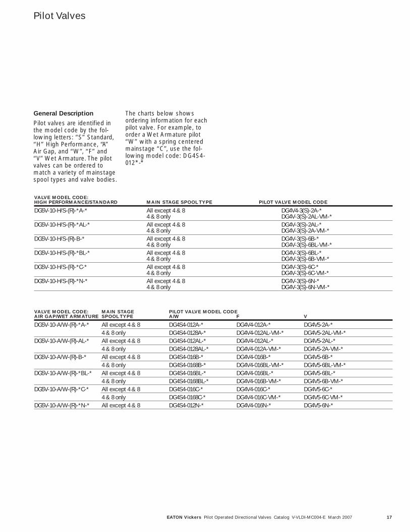
Pilot Valves
General Description
Pilot valves are identified inthe model code by the fol-lowing letters: ‘‘S’’ Standard,‘‘H’’ High Performance, ‘‘A’’Air Gap, and ‘‘W’’, ‘‘F’’ and‘‘V’’ Wet Armature. The pilotvalves can be ordered tomatch a variety of mainstagespool types and valve bodies.
The charts below showsordering information for eachpilot valve. For example, toorder a Wet Armature pilot‘‘W’’ with a spring centeredmainstage ‘‘C’’, use the fol-lowing model code: DG4S4-012*-*
VALVE MODEL CODE:HIGH PERFORMANCE/STANDARD MAIN STAGE SPOOL TYPE PILOT VALVE MODEL CODE
DG5V-10-H/S-(R)-*A-* All except 4 & 8 DG4V4-3(S)-2A-*4 & 8 only DG4V-3(S)-2AL-VM-*
DG5V-10-H/S-(R)-*AL-* All except 4 & 8 DG4V-3(S)-2AL-*4 & 8 only DG4V-3(S)-2A-VM-*
DG5V-10-H/S-(R)-B-* All except 4 & 8 DG4V-3(S)-6B-*4 & 8 only DG4V-3(S)-6BL-VM-*
DG5V-10-H/S-(R)-*BL-* All except 4 & 8 DG4V-3(S)-6BL-*4 & 8 only DG4V-3(S)-6B-VM-*
DG5V-10-H/S-(R)-*C-* All except 4 & 8 DG4V-3(S)-6C-*4 & 8 only DG4V-3(S)-6C-VM-*
DG5V-10-H/S-(R)-*N-* All except 4 & 8 DG4V-3(S)-6N-*4 & 8 only DG4V-3(S)-6N-VM-*
VALVE MODEL CODE: MAIN STAGE PILOT VALVE MODEL CODEAIR GAP/WET ARMATURE SPOOL TYPE A/W F V
DG5V-10-A/W-(R)-*A-* All except 4 & 8 DG4S4-012A-* DG4V4-012A-* DG4V5-2A-*4 & 8 only DG4S4-0128A-* DG4V4-012AL-VM-* DG4V5-2AL-VM-*
DG5V-10-A/W-(R)-AL-* All except 4 & 8 DG4S4-012AL-* DG4V4-012AL-* DG4V5-2AL-*4 & 8 only DG4S4-0128AL-* DG4V4-012A-VM-* DG4V5-2A-VM-*
DG5V-10-A/W-(R)-B-* All except 4 & 8 DG4S4-016B-* DG4V4-016B-* DG4V5-6B-*4 & 8 only DG4S4-0168B-* DG4V4-016BL-VM-* DG4V5-6BL-VM-*
DG5V-10-A/W-(R)-*BL-* All except 4 & 8 DG4S4-016BL-* DG4V4-016BL-* DG4V5-6BL-*4 & 8 only DG4S4-0168BL-* DG4V4-016B-VM-* DG4V5-6B-VM-*
DG5V-10-A/W-(R)-*C-* All except 4 & 8 DG4S4-016C-* DG4V4-016C-* DG4V5-6C-*4 & 8 only DG4S4-0168C-* DG4V4-016C-VM-* DG4V5-6C-VM-*
DG5V-10-A/W-(R)-*N-* All except 4 & 8 DG4S4-012N-* DG4V4-016N-* DG4V5-6N-*
18 EATON Vickers Pilot Operated Directional Valves Catalog V-VLDI-MC004-E March 2007
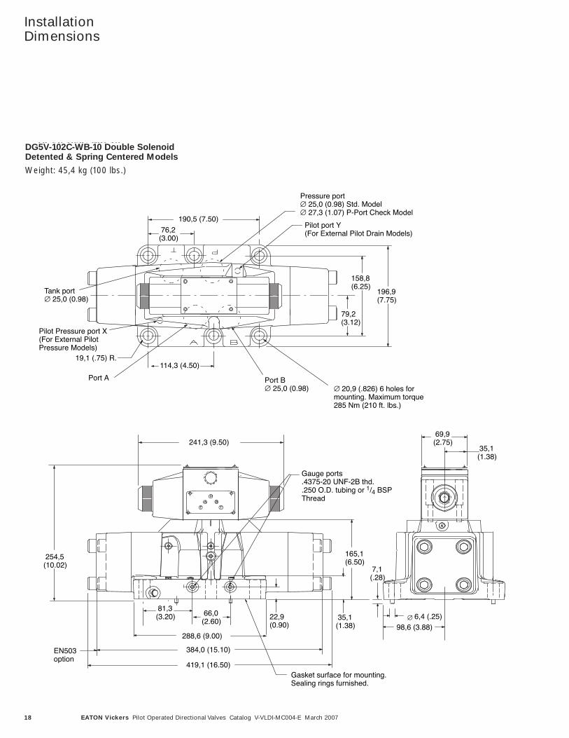
InstallationDimensions
76,2(3.00)
DG5V-102C-WB-10Double Solenoid Detented &Spring Centered Models
Weight: 45,4 kg (100 lbs.)
79,2(3.12)
158,8(6.25)
114,3 (4.50)
Pressure port∅ 25,0 (0.98) Std. Model∅ 27,3 (1.07) P-Port Check Model
∅ 20,9 (.826) 6 holes formounting. Maximum torque285 Nm (210 ft. lbs.)
Tank port∅ 25,0 (0.98)
Port A Port B∅ 25,0 (0.98)
196,9(7.75)
66,0(2.60)
81,3(3.20) 22,9
(0.90) 35,1(1.38)
165,1(6.50)
∅
7,1(.28)
Gauge ports.4375-20 UNF-2B thd..250 O.D. tubing or 1/4 BSPThread
Gasket surface for mounting.Sealing rings furnished.
19,1 (.75) R.
69,9(2.75)
35,1(1.38)
254,5(10.02)
Pilot Pressure port X(For External PilotPressure Models)
Pilot port Y(For External Pilot Drain Models)
190,5 (7.50)
98,6 (3.88)6,4 (.25)
288,6 (9.00)
419,1 (16.50)
241,3 (9.50)
384,0 (15.10)EN503option
DG5V-102C-WB-10 Double SolenoidDetented & Spring Centered Models
Weight: 45,4 kg (100 lbs.)
19EATON Vickers Pilot Operated Directional Valves Catalog V-VLDI-MC004-E March 2007
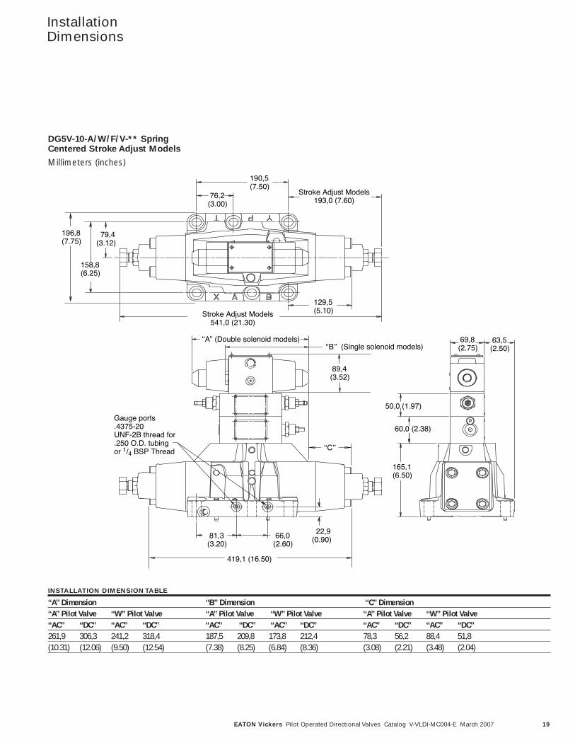
DG5V-10-A/W/F/V-**Spring Centered Stroke AdjustModelsMillimeters (inches)
190,5(7.50)
76,2 (3.00)
Stroke Adjust Models193,0 (7.60)
129,5(5.10)
79,4(3.12)
158,8(6.25)
196,8(7.75)
Stroke Adjust Models 541,0 (21.30)
ʻʻAʼʼ (Double solenoid models)ʻʻBʼʼ (Single solenoid models)
89,4(3.52)
22,9(0.90) 66,0
(2.60) 81,3 (3.20)
Gauge ports.4375-20UNF-2B thread for.250 O.D. tubingor 1/4 BSP Thread
419,1 (16.50)
69,8 (2.75)
63,5(2.50)
165,1(6.50)
50,0 (1.97)
60,0 (2.38)
ʻʻCʼʼ
DG5V-10-A/W/F/V-** SpringCentered Stroke Adjust Models
Millimeters (inches)
INSTALLATION DIMENSION TABLE
‘‘A’’ Dimension ‘‘B’’ Dimension ‘‘C’’ Dimension‘‘A’’ Pilot Valve ‘‘W’’ Pilot Valve ‘‘A’’ Pilot Valve ‘‘W’’ Pilot Valve ‘‘A’’ Pilot Valve ‘‘W’’ Pilot Valve‘‘AC’’ ‘‘DC’’ ‘‘AC’’ ‘‘DC’’ ‘‘AC’’ ‘‘DC’’ ‘‘AC’’ ‘‘DC’’ ‘‘AC’’ ‘‘DC’’ ‘‘AC’’ ‘‘DC’’261,9 306,3 241,2 318,4 187,5 209,8 173,8 212,4 78,3 56,2 88,4 51,8(10.31) (12.06) (9.50) (12.54) (7.38) (8.25) (6.84) (8.36) (3.08) (2.21) (3.48) (2.04)
InstallationDimensions
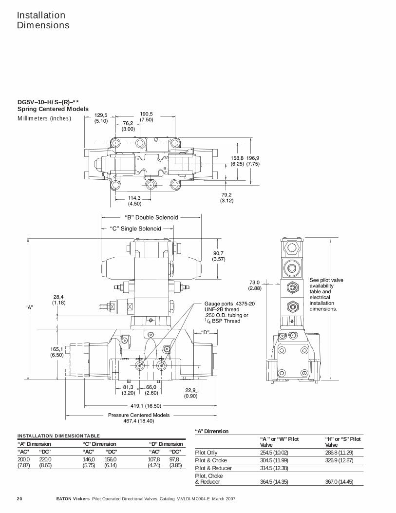
DG5V–10–H/S–(R)–Spring Centered ModelsMillimeters (inches)
ʻʻA ʼʼ or ʻʻWʼʼ Pilot ʻʻHʼʼ or ʻʻSʼʼ Pilot
ʻʻAʼʼ Dimension
ʻʻAʼʼ
ʻʻDʼʼ
Pressure Centered Models467,4 (18.40)
419,1 (16.50)
ʻʻBʼʼ Double Solenoid
ʻʻCʼʼ Single Solenoid
Gauge ports .4375-20UNF-2B thread.250 O.D. tubing or1/4 BSP Thread
81,3(3.20)
66,0 (2.60) 22,9
(0.90)
165,1(6.50)
28,4 (1.18)
90,7 (3.57)
129,5(5.10)
190,5(7.50)
76,2(3.00)
114,3 (4.50)
196,9(7.75)
158,8(6.25)
79,2(3.12)
73,0(2.88)
See pilot valveavailabilitytable andelectricalinstallationdimensions.
20
InstallationDimensions
DG5V–10–H/S–(R)–** Spring Centered Models
Millimeters (inches)
INSTALLATION DIMENSION TABLE
‘‘A’’ Dimension ‘‘C’’ Dimension ‘‘D’’ Dimension‘‘AC’’ ‘‘DC’’ ‘‘AC’’ ‘‘DC’’ ‘‘AC’’ ‘‘DC’’ 200,0 220,0 146,0 156,0 107,8 97,8(7.87) (8.66) (5.75) (6.14) (4.24) (3.85)
‘‘A’’ Dimension‘‘A ’’ or ‘‘W’’ Pilot ‘‘H’’ or ‘‘S’’ PilotValve Valve
Pilot Only 254.5 (10.02) 286.8 (11.29)Pilot & Choke 304.5 (11.99) 326.9 (12.87)Pilot & Reducer 314.5 (12.38)Pilot, Choke& Reducer 364.5 (14.35) 367.0 (14.45)
EATON Vickers Pilot Operated Directional Valves Catalog V-VLDI-MC004-E March 2007
21EATON Vickers Pilot Operated Directional Valves Catalog V-VLDI-MC004-E March 2007
InstallationDimensions
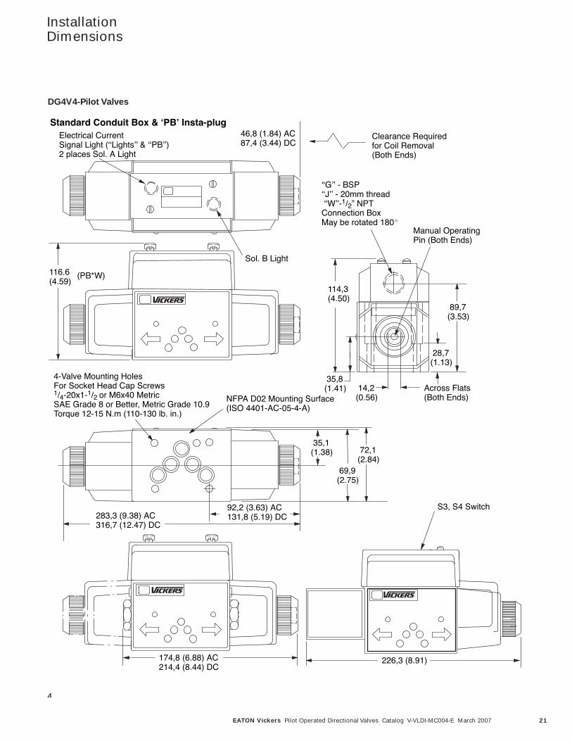
4
Electrical CurrentSignal Light (ʻʻLightsʼʼ & ʻʻPBʼʼ)2 places Sol. A Light
Sol. B Light
Clearance Requiredfor Coil Removal(Both Ends)
116.6(4.59)
ʻʻGʼʼ - BSP ʻʻJʼʼ - 20mm threadʻʻWʼʼ-1/2” NPTConnection Box May be rotated 180
Manual OperatingPin (Both Ends)
Across Flats(Both Ends)
114,3 (4.50)
89,7 (3.53)
35,8 (1.41) 14,2
(0.56)
28,7(1.13)
4-Valve Mounting HolesFor Socket Head Cap Screws1/4-20x1-1/2 or M6x40 MetricSAE Grade 8 or Better, Metric Grade 10.9Torque 12-15 N.m (110-130 lb. in.)
NFPA D02 Mounting Surface(ISO 4401-AC-05-4-A)
92,2 (3.63) AC131,8 (5.19) DC
46,8 (1.84) AC87,4 (3.44) DC
283,3 (9.38) AC316,7 (12.47) DC
35,1(1.38)
69,9(2.75)
72,1(2.84)
174,8 (6.88) AC 214,4 (8.44) DC
226,3 (8.91)
(PB*W)
S3, S4 Switch
Standard Conduit Box & ʻPBʼ Insta-plug
DG4V4-Pilot ValvesDG4V4-Pilot Valves
22 EATON Vickers Pilot Operated Directional Valves Catalog V-VLDI-MC004-E March 2007
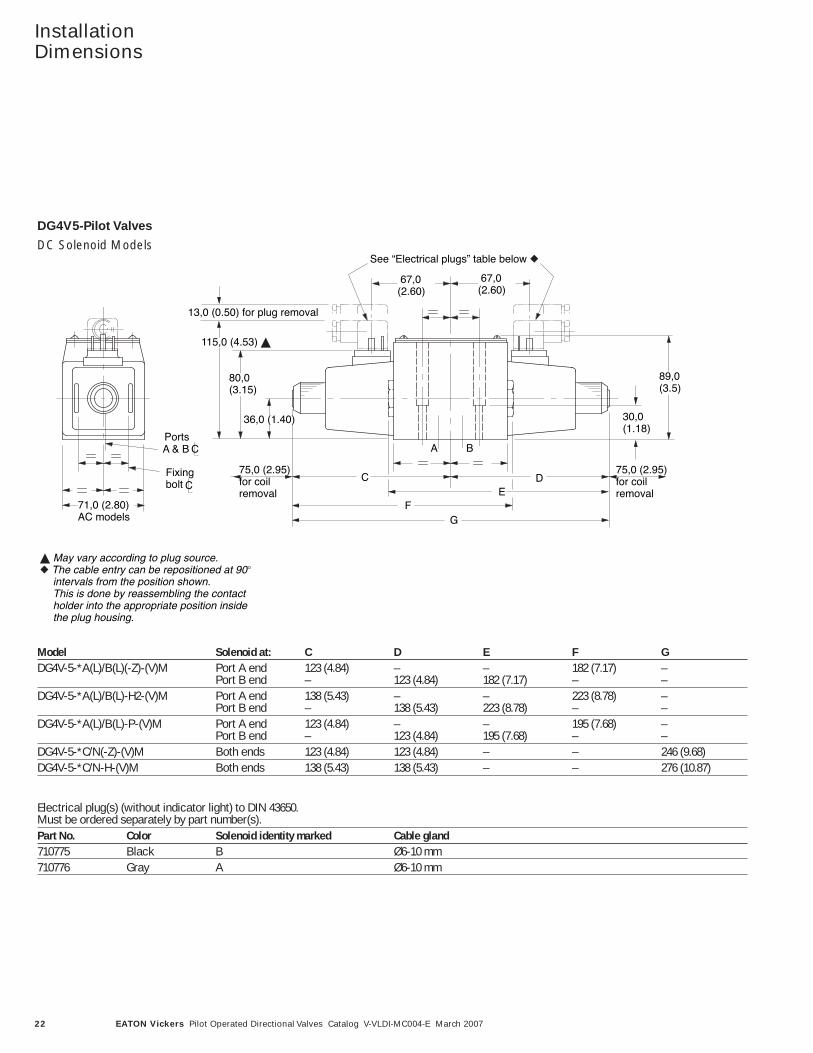
InstallationDimensions
AC Solenoid Models
May vary according to plug source.The cable entry can be repositioned at 90intervals from the position shown. This is done by reassembling the contactholder into the appropriate position insidethe plug housing.
13,0 (0.50) for plug removal
115,0 (4.53)
Fixingbolt
75,0 (2.95)for coilremoval
80,0(3.15)
89,0(3.5)
36,0 (1.40) 30,0(1.18)
C DE
FG
A B
67,0(2.60)
67,0(2.60)
See “Electrical plugs” table below
CA & BPorts
C
71,0 (2.80)AC models
DG4V5-Pilot Valves
75,0 (2.95)for coilremoval
Model Solenoid at: C D E F GDG4V-5-*A(L)/B(L)(-Z)-(V)M Port A end 123 (4.84) – – 182 (7.17) –
Port B end – 123 (4.84) 182 (7.17) – –DG4V-5-*A(L)/B(L)-H2-(V)M Port A end 138 (5.43) – – 223 (8.78) –
Port B end – 138 (5.43) 223 (8.78) – –DG4V-5-*A(L)/B(L)-P-(V)M Port A end 123 (4.84) – – 195 (7.68) –
Port B end – 123 (4.84) 195 (7.68) – –DG4V-5-*C/N(-Z)-(V)M Both ends 123 (4.84) 123 (4.84) – – 246 (9.68)DG4V-5-*C/N-H-(V)M Both ends 138 (5.43) 138 (5.43) – – 276 (10.87)
Electrical plug(s) (without indicator light) to DIN 43650.Must be ordered separately by part number(s).Part No. Color Solenoid identity marked Cable gland710775 Black B Ø6-10 mm710776 Gray A Ø6-10 mm
DG4V5-Pilot Valves
DC Solenoid Models
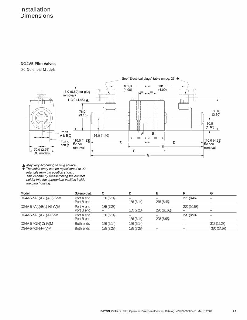
DC Solenoid Models
May vary according to plug source.The cable entry can be repositioned at 90intervals from the position shown. This is done by reassembling the contactholder into the appropriate position insidethe plug housing.
C DE
FG
A B
30,0(1.18)
89,0(3.50)
36,0 (1.40)
78,0(3.10)
113,0 (4.45)
13,0 (0.50) for plugremoval
Fixingbolt
CA & BPorts
C70,0 (2.76)DC models
101,0(4.00)
See “Electrical plugs” table on pg. 23.
101,0(4.00)
110,0 (4.33)for coilremoval
DG4V5-Pilot Valves
110,0 (4.33)for coilremoval
23EATON Vickers Pilot Operated Directional Valves Catalog V-VLDI-MC004-E March 2007
InstallationDimensions
Model Solenoid at: C D E F GDG4V-5-*A(L)/B(L)-(-Z)-(V)M Port A end 156 (6.14) – – 215 (8.46) –
Port B end – 156 (6.14) 215 (8.46) – –DG4V-5-*A(L)/B(L)-H2-(V)M Port A end 185 (7.28) – – 270 (10.63) –
Port B end) – 185 (7.28) 270 (10.63) – –DG4V-5-*A(L)/B(L)-P-(V)M Port A end 156 (6.14) – – 228 (8.98) –
Port B end – 156 (6.14) 228 (8.98) – –DG4V-5-*C/N(-Z)-(V)M Both ends 156 (6.14) 156 (6.14) – – 312 (12.28)DG4V-5-*C/N-H-(V)M Both ends 185 (7.28) 185 (7.28) – – 370 (14.57)
DG4V5-Pilot Valves
DC Solenoid Models
24 EATON Vickers Pilot Operated Directional Valves Catalog V-VLDI-MC004-E March 2007
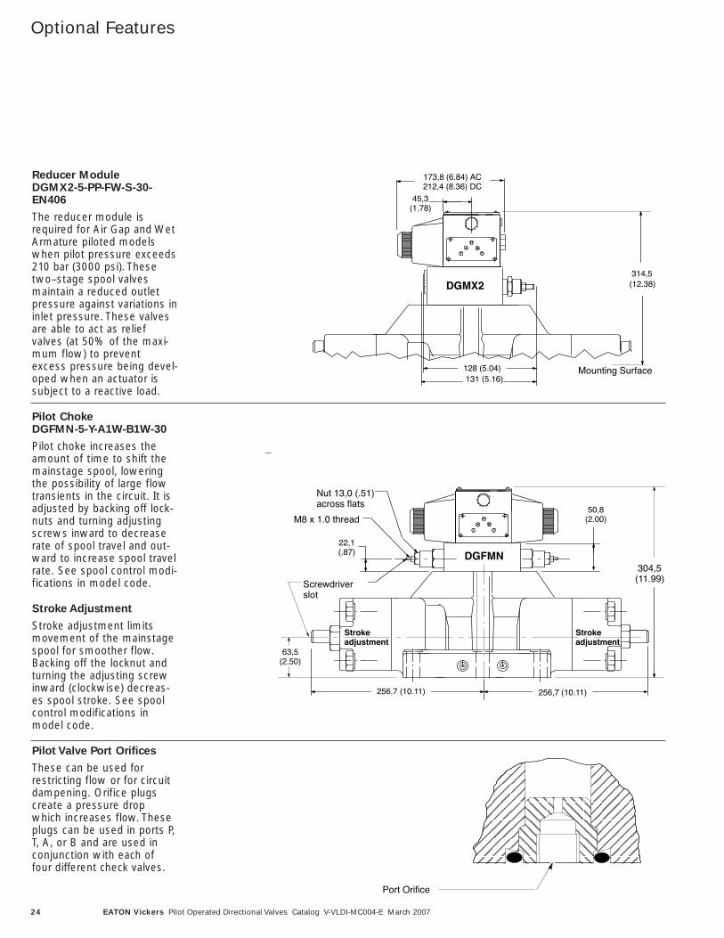
Optional Features
22,1(.87)
Screwdriverslot
50,8(2.00)M8 x 1.0 thread
Nut 13,0 (.51) across flats
63,5(2.50)
Strokeadjustment
Strokeadjustment
304,5(11.99)
DGFMN
256,7 (10.11)256,7 (10.11)
Port Orifice
DGMX2
45,3(1.78)
173,8 (6.84) AC212,4 (8.36) DC
128 (5.04) Mounting Surface
314,5(12.38)
131 (5.16)
Reducer Module DGMX2-5-PP-FW-S-30-EN406
The reducer module isrequired for Air Gap and WetArmature piloted modelswhen pilot pressure exceeds210 bar (3000 psi). Thesetwo–stage spool valvesmaintain a reduced outletpressure against variations ininlet pressure. These valvesare able to act as reliefvalves (at 50% of the maxi-mum flow) to preventexcess pressure being devel-oped when an actuator issubject to a reactive load.
Pilot ChokeDGFMN-5-Y-A1W-B1W-30
Pilot choke increases theamount of time to shift themainstage spool, loweringthe possibility of large flowtransients in the circuit. It isadjusted by backing off lock-nuts and turning adjustingscrews inward to decreaserate of spool travel and out-ward to increase spool travelrate. See spool control modi-fications in model code.
Stroke Adjustment
Stroke adjustment limitsmovement of the mainstagespool for smoother flow.Backing off the locknut andturning the adjusting screwinward (clockwise) decreas-es spool stroke. See spoolcontrol modifications inmodel code.
Pilot Valve Port Orifices
These can be used forrestricting flow or for circuitdampening. Orifice plugscreate a pressure dropwhich increases flow. Theseplugs can be used in ports P,T, A, or B and are used inconjunction with each offour different check valves.
25EATON Vickers Pilot Operated Directional Valves Catalog V-VLDI-MC004-E March 2007
Optional Features
ʻʻS SPRINGʼʼ
ʻʻR SPRINGʼʼ
ʻʻK SPRINGʼʼ
100 300 500 700 900
20
18
16
12
10
6
2
P
OR
D E
RU
SS
ER
P–
rab
P
OR
D E
RU
SS
ER
P–
is p
25 75 125 175 225
40
80
120
160
200
240
280
300
FLOW – L/min
FLOW – USgpm
Pressure Drop Across Check Valve
ʻʻQ SPRINGʼʼ
4
8
147,3(5.80)
467,4 (18.4)
254,5 (10.02)
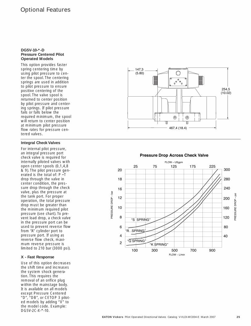
DG5V-10-*-D Pressure Centered PilotOperated Models
This option provides fasterspring centering time byusing pilot pressure to cen-ter the spool. The centeringsprings are used in additionto pilot pressure to ensurepositive centering of thespool. The valve spool isreturned to center positionby pilot pressure and center-ing springs. If pilot pressurefails or falls below therequired minimum, the spoolwill return to center positionat minimum pilot pressureflow rates for pressure cen-tered valves.
Integral Check Valves
For internal pilot pressure,an integral pressure portcheck valve is required forinternally piloted valves withopen center spools (0,1,4,8& 9). The pilot pressure gen-erated is the total of: P Tdrop through the valve incenter condition, the pres-sure drop through the checkvalve, plus the pressure atthe tank port. For properoperation, the total pressuredrop must be greater thanthe minimum required pilotpressure (see chart). To pre-vent load drop, a check valvein the pressure port can beused to prevent reverse flowfrom ‘‘A’’ cylinder port topressure port. If using asreverse flow check, maxi-mum reverse pressure islimited to 210 bar (3000 psi).
X - Fast Response
Use of this option decreasesthe shift time and increasesthe system shock genera-tion. This requires theremoval of an orifice plugwithin the mainstage body.It is available on all modelsexcept Pressure Centered‘‘D’’, ‘‘DB’’, or CETOP 3 pilot-ed models by adding ‘‘X’’ tothe model code. Example:DG5V-2C-X-*-10.
26 EATON Vickers Pilot Operated Directional Valves Catalog V-VLDI-MC004-E March 2007
ElectricalInformation
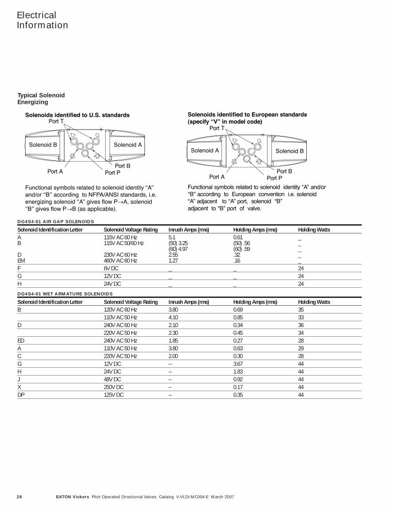
Solenoids identified to European standards(specify “V” in model code)
Functional symbols related to solenoid identity ̒ ʻA̓ʼ and/orʻ̒Bʼ̓ according to European convention i.e. solenoidʻ̒ A̓ʼ adjacent to ʻ̒ A̓ʼ port, solenoid ʻ̒Bʼ̓adjacent to ʻ̒Bʼ̓ port of valve.
Port T
Port BPort PPort A
Solenoid A Solenoid B
Typical Solenoid Energizing
Solenoids identified to U.S. standards
Functional symbols related to solenoid identity ʻʻAʼʼand/or ʻʻBʼʼ according to NFPA/ANSI standards, i.e.energizing solenoid ʻʻAʼʼ gives flow P→A, solenoidʻʻBʼʼ gives flow P→B (as applicable).
Port T
Port BPort PPort A
Solenoid B Solenoid A
DG4S4-01 AIR GAP SOLENOIDS
Solenoid Identification Letter Solenoid Voltage Rating Inrush Amps (rms) Holding Amps (rms) Holding WattsA 115V AC 60 Hz 5.1 0.61 _B 115V AC 50/60 Hz (50) 3.25 (50) .56 _
(60) 4.97 (60) .59 _D 230V AC 60 Hz 2.55 .32 _EM 460V AC 60 Hz 1.27 .16 _F 6V DC _ _ 24G 12V DC _ _ 24H 24V DC _ _ 24
DG4S4-01 WET ARMATURE SOLENOIDS
Solenoid Identification Letter Solenoid Voltage Rating Inrush Amps (rms) Holding Amps (rms) Holding WattsB 120V AC 60 Hz 3.80 0.69 35
110V AC 50 Hz 4.10 0.85 33D 240V AC 60 Hz 2.10 0.34 36
220V AC 50 Hz 2.30 0.45 34ED 240V AC 50 Hz 1.85 0.27 28A 110V AC 50 Hz 3.80 0.63 29C 220V AC 50 Hz 2.00 0.30 28G 12V DC – 3.67 44H 24V DC – 1.83 44J 48V DC – 0.92 44X 250V DC – 0.17 44DP 125V DC – 0.35 44
Typical SolenoidEnergizing
27EATON Vickers Pilot Operated Directional Valves Catalog V-VLDI-MC004-E March 2007
ElectricalInformation
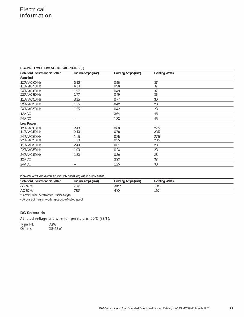
DG4V4-01 WET ARMATURE SOLENOIDS (F)
Solenoid Identification Letter Inrush Amps (rms) Holding Amps (rms) Holding WattsStandard120V AC 60 Hz 3.95 0.98 37110V AC 50 Hz 4.10 0.98 37240V AC 60 Hz 1.97 0.49 37220V AC 50 Hz 1.77 0.49 36110V AC 50 Hz 3.25 0.77 30220V AC 50 Hz 1.55 0.42 28240V AC 50 Hz 1.55 0.42 2812V DC 3.64 4524V DC – 1.83 45Low Power120V AC 60 Hz 2.40 0.69 27.5110V AC 50 Hz 2.40 0.78 28.5240V AC 60 Hz 1.15 0.25 27.5220V AC 50 Hz 1.10 0.35 28.5110V AC 50 Hz 2.40 0.61 23220V AC 50 Hz 1.00 0.24 23240V AC 50 Hz 1.20 0.26 2312V DC 2.33 3324V DC – 1.25 30
DG4V5 WET ARMATURE SOLENOIDS (V) AC SOLENOIDS
Solenoid Identification Letter Inrush Amps (rms) Holding Amps (rms) Holding WattsAC 50 Hz 700* 375 • 105AC 60 Hz 750* 440• 130* Armature fully retracted, 1st half-cyle• At start of normal working stroke of valve spool.
DC Solenoids
At rated voltage and wire temperature of 20˚C (68˚F):
Type HL 32WOthers 38-42W
28 EATON Vickers Pilot Operated Directional Valves Catalog V-VLDI-MC004-E March 2007
ElectricalInformation
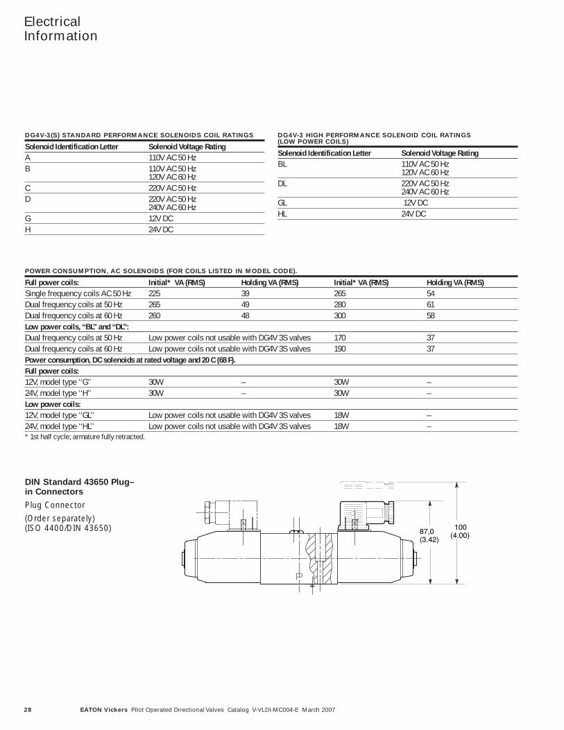
DG4V-3(S) STANDARD PERFORMANCE SOLENOIDS COIL RATINGS
Solenoid Identification Letter Solenoid Voltage RatingA 110V AC 50 HzB 110V AC 50 Hz
120V AC 60 HzC 220V AC 50 HzD 220V AC 50 Hz
240V AC 60 HzG 12V DCH 24V DC
DG4V-3 HIGH PERFORMANCE SOLENOID COIL RATINGS (LOW POWER COILS)
Solenoid Identification Letter Solenoid Voltage RatingBL 110V AC 50 Hz
120V AC 60 HzDL 220V AC 50 Hz
240V AC 60 HzGL 12V DCHL 24V DC
POWER CONSUMPTION, AC SOLENOIDS (FOR COILS LISTED IN MODEL CODE).
Full power coils: Initial* VA (RMS) Holding VA (RMS) Initial* VA (RMS) Holding VA (RMS)Single frequency coils AC 50 Hz 225 39 265 54Dual frequency coils at 50 Hz 265 49 280 61Dual frequency coils at 60 Hz 260 48 300 58Low power coils, ‘‘BL’’ and ‘‘DL’’:Dual frequency coils at 50 Hz Low power coils not usable with DG4V 3S valves 170 37Dual frequency coils at 60 Hz Low power coils not usable with DG4V 3S valves 190 37Power consumption, DC solenoids at rated voltage and 20 C (68 F).Full power coils:12V, model type ‘‘G’’ 30W – 30W –24V, model type ‘‘H’’ 30W – 30W –Low power coils:12V, model type ‘‘GL’’ Low power coils not usable with DG4V 3S valves 18W –24V, model type ‘‘HL’’ Low power coils not usable with DG4V 3S valves 18W –* 1st half cycle; armature fully retracted.
DIN Standard 43650 Plug–in Connectors
Plug Connector
(Order separately) (ISO 4400/DIN 43650) 87,0
(3.42)
100 (4.00)
29EATON Vickers Pilot Operated Directional Valves Catalog V-VLDI-MC004-E March 2007
ElectricalInformation
116,6 (4.59)
114,3 (4.50)
230,6 (9.08) AC262,6 (10.34) DC
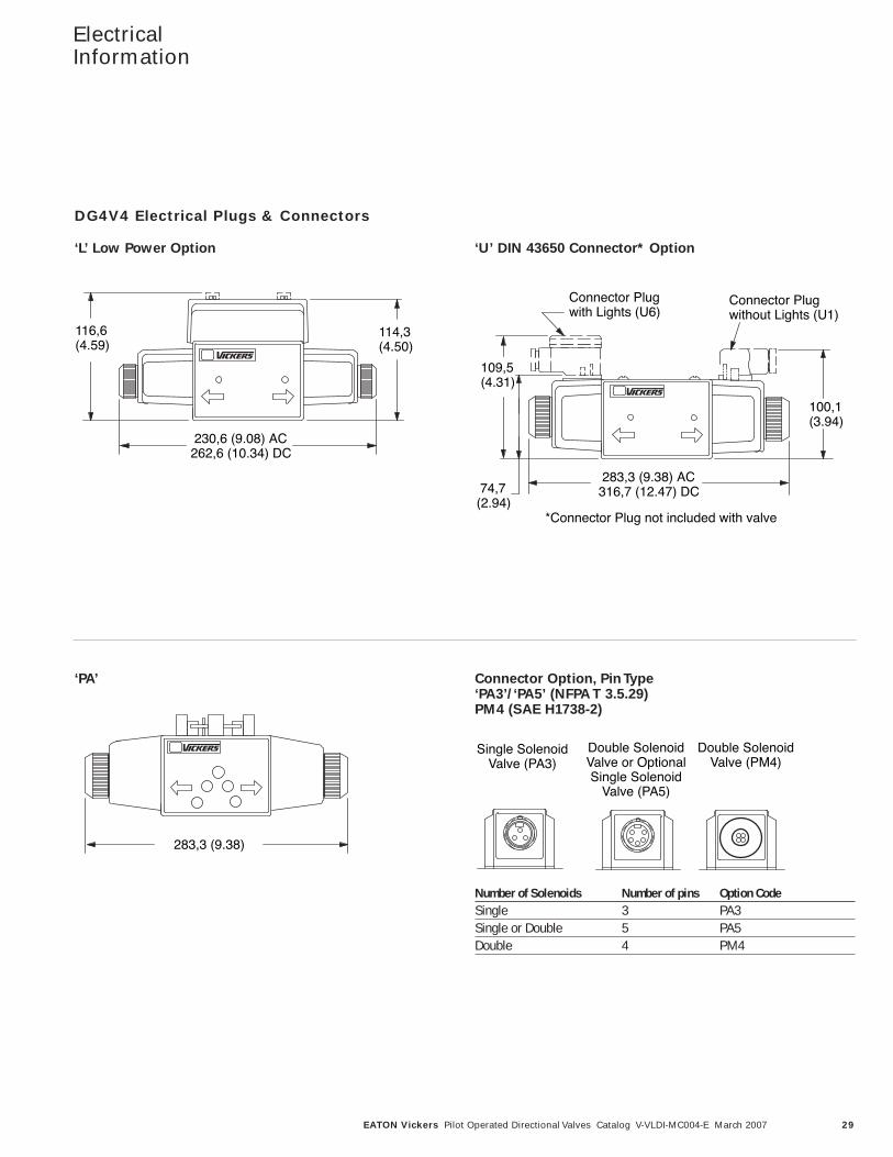
DG4V4 Electrical Plugs & Connectors
‘L’ Low Power Option ‘U’ DIN 43650 Connector* Option
‘PA’ Connector Option, Pin Type‘PA3’/‘PA5’ (NFPA T 3.5.29)PM4 (SAE H1738-2)
Connector Plugwith Lights (U6)
Connector Plugwithout Lights (U1)
*Connector Plug not included with valve
100,1(3.94)
283,3 (9.38) AC316,7 (12.47) DC
109,5(4.31)
74,7(2.94)
283,3 (9.38)
Single SolenoidValve (PA3)
Double SolenoidValve or OptionalSingle Solenoid
Valve (PA5)
Double SolenoidValve (PM4)
Number of Solenoids Number of pins Option CodeSingle 3 PA3Single or Double 5 PA5Double 4 PM4
30 EATON Vickers Pilot Operated Directional Valves Catalog V-VLDI-MC004-E March 2007
ElectricalInformation
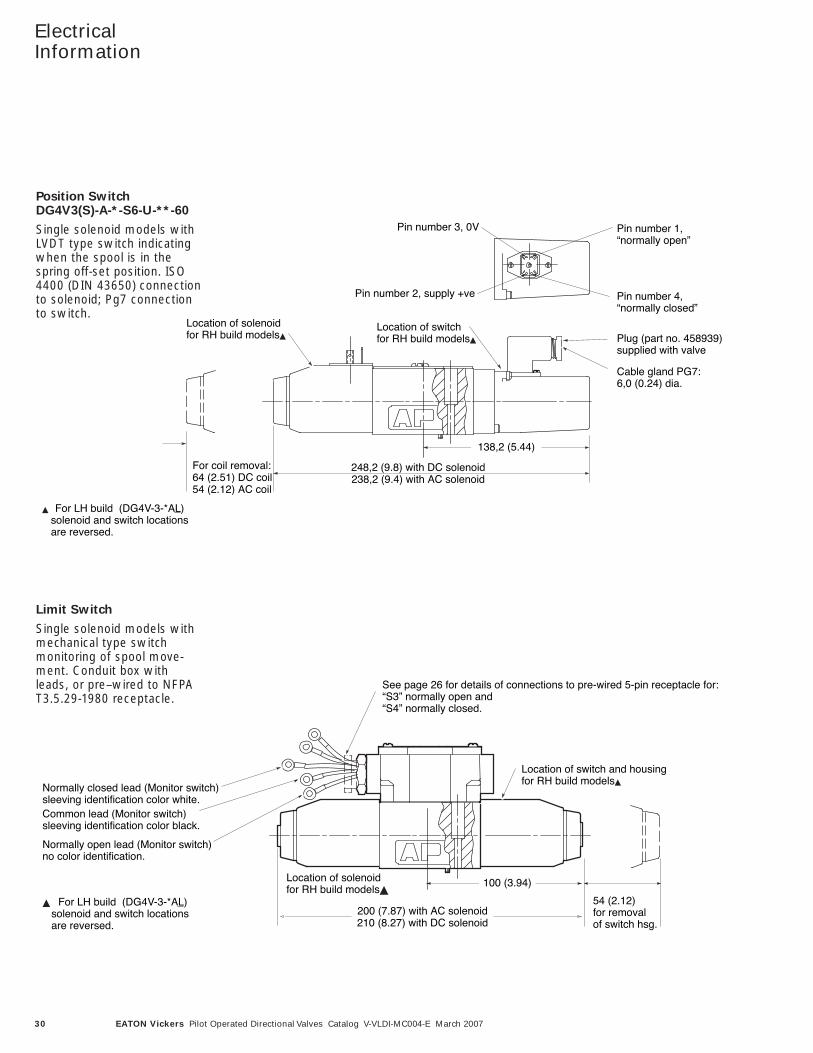
248,2 (9.8) with DC solenoid238,2 (9.4) with AC solenoid
Single solenoid models with LVDT typeswitch indicating when the spool is inthe spring off-set position. ISO 4400(DIN 43650) connection to solenoid;Pg7 connection to switch.
For coil removal:64 (2.51) DC coil54 (2.12) AC coil
138,2 (5.44)
Location of solenoidfor RH build models
Location of switchfor RH build models Plug (part no. 458939)
supplied with valve
Cable gland PG7:6,0 (0.24) dia.
Pin number 2, supply +ve
Pin number 3, 0V Pin number 1,“normally open”
Pin number 4,“normally closed”
For LH build (DG4V-3-*AL) solenoid and switch locations are reversed.
DG4V3(S)-A-*-S6-U-**-60Position SwitchDG4V3(S)-A-*-S6-U-**-60
Single solenoid models withLVDT type switch indicatingwhen the spool is in thespring off-set position. ISO4400 (DIN 43650) connectionto solenoid; Pg7 connectionto switch.
200 (7.87) with AC solenoid210 (8.27) with DC solenoid
See page 26 for details of connections to pre-wired 5-pin receptacle for:“S3” normally open and“S4” normally closed.
DG4V 3(S) A S4 FPAW 2 60DG4V-3(S)-A-*-**-S5-F-*2-60
For LH build (DG4V-3-*AL) solenoid and switch locations are reversed.
100 (3.94)
Location of switch and housingfor RH build models
Normally closed lead (Monitor switch)sleeving identification color white.Common lead (Monitor switch)sleeving identification color black.
Normally open lead (Monitor switch)no color identification.
Location of solenoidfor RH build models
54 (2.12)for removalof switch hsg.
Single solenoid models with mechanical type switchmonitoring of spool movement.Conduit box with leads, or pre–wired to NFPAT3.5.29-1980 receptacle.
Limit Switch
Single solenoid models withmechanical type switchmonitoring of spool move-ment. Conduit box withleads, or pre–wired to NFPAT3.5.29-1980 receptacle.
31EATON Vickers Pilot Operated Directional Valves Catalog V-VLDI-MC004-E March 2007
ElectricalInformation
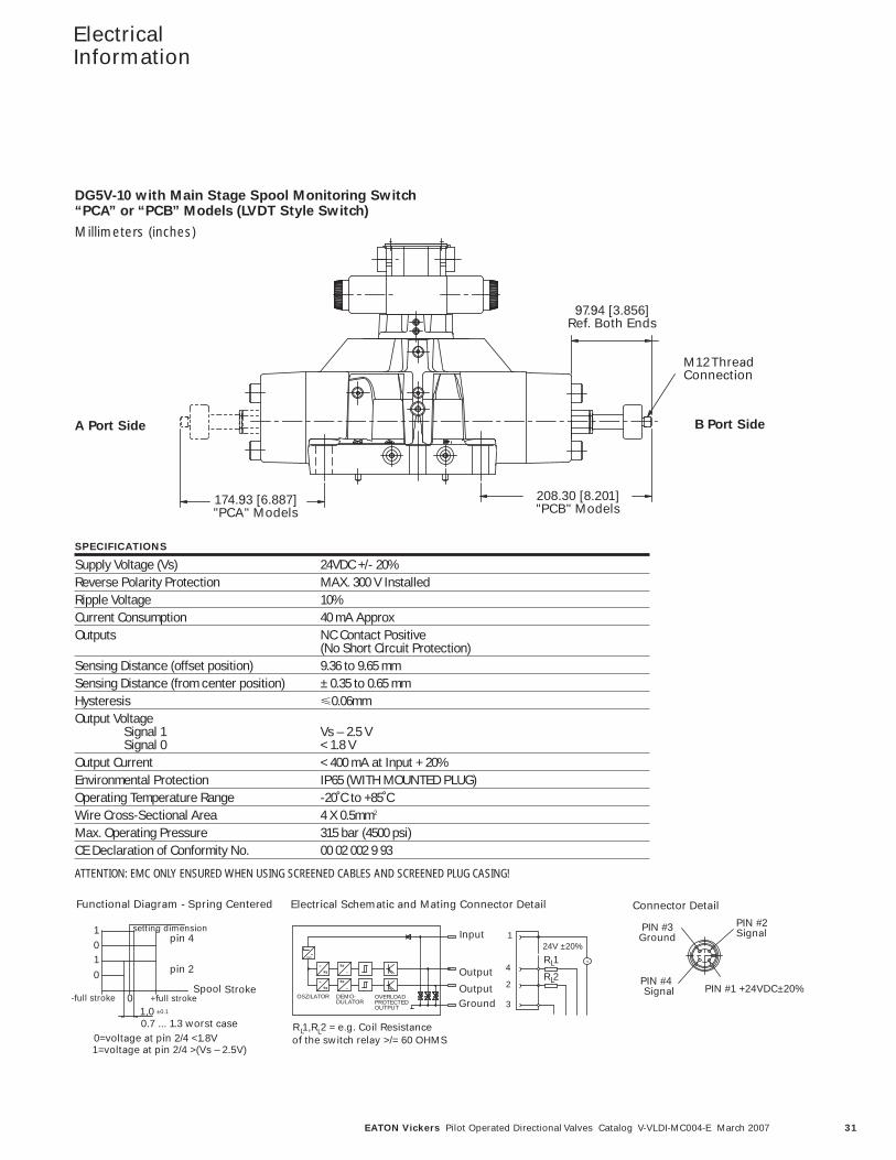
208.30 [8.201]"PCB" Models
174.93 [6.887]"PCA" Models
97.94 [3.856]Ref. Both Ends
M12 ThreadConnection
0.7 ... 1.3 worst case0=voltage at pin 2/4 <1.8V 1=voltage at pin 2/4 >(Vs – 2.5V)
Stroke -full stroke 0
pin 2
+full strokeSpool
pin 4 setting dimension
0 1 0
1,0 ±0.1
Functional Diagram - Spring Centered
1
Connector Detail
PIN #2 Signal
PIN #1 +24VDC±20%PIN #4 Signal
PIN #3 Ground
=
=
=
stab
=
=
24V ±20%
4
3Ground
Output
Output 2
LR 1
LR 2
Input 1
=
OSZILATOR DEMO-DULATOR
OVERLOADPROTECTEDOUTPUT
R 1,R 2 = e.g. Coil Resistanceof the switch relay >/= 60 OHMS
L L
Electrical Schematic and Mating Connector Detail
DG5V-10 with Main Stage Spool Monitoring Switch“PCA” or “PCB” Models (LVDT Style Switch)
Millimeters (inches)
SPECIFICATIONS
Supply Voltage (Vs) 24VDC +/- 20%Reverse Polarity Protection MAX. 300 V InstalledRipple Voltage 10%Current Consumption 40 mA ApproxOutputs NC Contact Positive
(No Short Circuit Protection) Sensing Distance (offset position) 9.36 to 9.65 mmSensing Distance (from center position) ± 0.35 to 0.65 mmHysteresis �0.06mmOutput Voltage
Signal 1 Vs – 2.5 VSignal 0 < 1.8 V
Output Current < 400 mA at Input + 20%Environmental Protection IP65 (WITH MOUNTED PLUG)Operating Temperature Range -20˚C to +85˚CWire Cross-Sectional Area 4 X 0.5mm2
Max. Operating Pressure 315 bar (4500 psi) CE Declaration of Conformity No. 00 02 002 9 93
ATTENTION: EMC ONLY ENSURED WHEN USING SCREENED CABLES AND SCREENED PLUG CASING!
A Port Side B Port Side
32 EATON Vickers Pilot Operated Directional Valves Catalog V-VLDI-MC004-E March 2007
ElectricalInformation
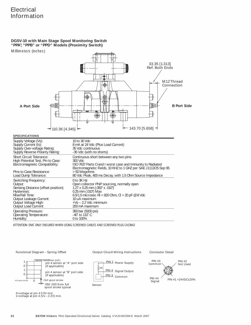
Connector Detail
110.36 [4.345] 143.70 [5.658]
33.35 [1.313]Ref. Both Ends
PIN #2 SignalPIN #3
Ground
stab=
24V ±20%
R 1
Input 1
Electrical Schematic and Mating Connector Detail
M12 ThreadConnection
0=voltage at pin 2/4 <1.8V 1=voltage at pin 2/4 >(Vs – 2.5V)
+full spool stroke
1=voltage at pin 4 (Vs – 2.2V) min.0=voltage at pin 4 0.5V min.
0-full spool stroke
pin 4 sensor at "B" port side
pin 4 sensor at "A" port sidecenter condition (ref.)
(if applicable)
(if applicable)
.050 .000 from full spool stroke typical
Sensor
10K
PIN 3
PIN 4
PIN 1
Common
Signal Output
Power Supply1
010
Functional Diagram - Spring Offset
PIN #2 Not Used
PIN #1 +24VDC±20%
PIN #3 Common
PIN #4 Signal
of the switch relay >/= 60 OHMS
Output Circuit Wiring Instructions Connector Detail
SPECIFICATIONS
Supply Voltage (Vs): 10 to 30 VdcSupply Current (Is): 8 mA at 24 Vdc (Plus Load Current)Supply Over-voltage Rating: 35 Vdc continuousSupply Reverse Polarity Rating: -35 Vdc (with no shorts)Short Circuit Tolerance: Continuous short between any two pinsHigh Potential Test, Pin to Case: 300 VdcElectromagnetic Compatibility: ISO 7637 Parts O and I worst case and Immunity to Radiated
Electromagnetic Fields, 10 KHZ to 1 GHZ per SAE J1113/25 Sep 95Pins to Case Resistance: > 50 MegohmsLoad Dump Tolerance: 80 Vdc Peak, 400 ms Decay, with 1.5 Ohm Source ImpedanceSwitching Frequency: 0 to 3K HzOutput: Open collector PNP sourcing, normally openSensing Distance (offset position): 1.27 ± 0.25 mm (.050" ± .010")Hysteresis: 0.25 mm (.010") MaxRise/Fall Time: 6.5/1.5 microsec Rl = 820 Ohm, Cl = 20 pF @ 8 VdcOutput Leakage Current: 10 uA maximumOutput Voltage High: +Vs – 2.2 Vdc minimumOutput Load Current: 200 mA maximumOperating Pressure: 350 bar (5000 psi)Operating Temperature: -40˚ to 110˚ C Humidity: 0 to 100%
ATTENTION: EMC ONLY ENSURED WHEN USING SCREENED CABLES AND SCREENED PLUG CASING!
DG5V-10 with Main Stage Spool Monitoring Switch“PPA”, “PPB” or “PPD” Models (Proximity Switch)
Millimeters (inches)
A Port Side B Port Side
33EATON Vickers Pilot Operated Directional Valves Catalog V-VLDI-MC004-E March 2007
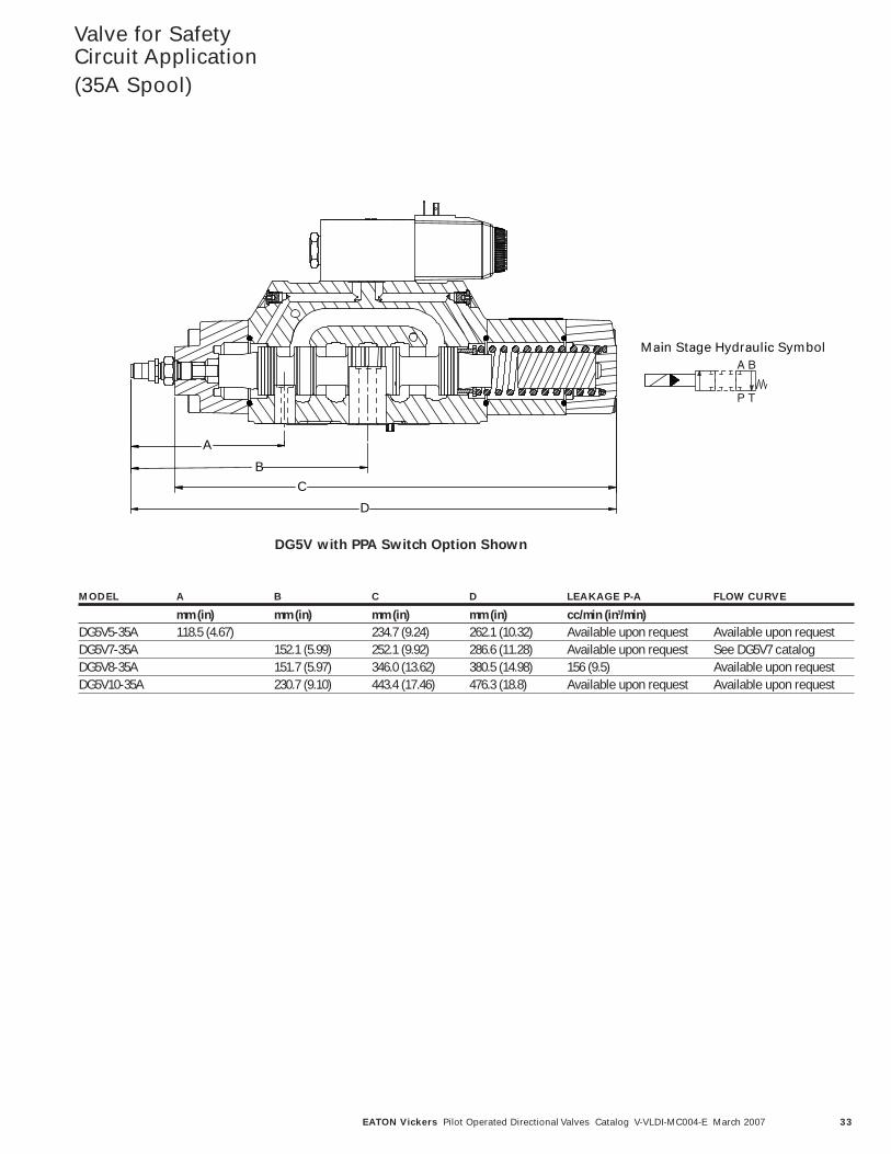
Valve for SafetyCircuit Application (35A Spool)
D
A
C
B
Main Stage Hydraulic SymbolA B
P T
MODEL A B C D LEAKAGE P-A FLOW CURVE
mm (in) mm (in) mm (in) mm (in) cc/min (in3/min)DG5V5-35A 118.5 (4.67) 234.7 (9.24) 262.1 (10.32) Available upon request Available upon requestDG5V7-35A 152.1 (5.99) 252.1 (9.92) 286.6 (11.28) Available upon request See DG5V7 catalogDG5V8-35A 151.7 (5.97) 346.0 (13.62) 380.5 (14.98) 156 (9.5) Available upon requestDG5V10-35A 230.7 (9.10) 443.4 (17.46) 476.3 (18.8) Available upon request Available upon request
DG5V with PPA Switch Option Shown
34 EATON Vickers Pilot Operated Directional Valves Catalog V-VLDI-MC004-E March 2007
ElectricalInformation
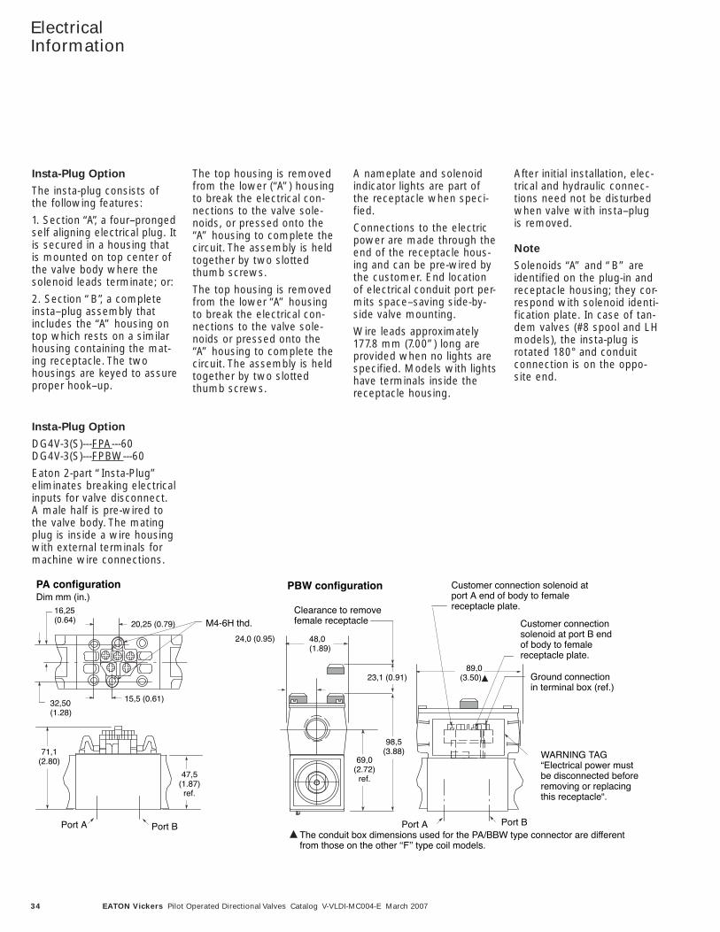
Insta-Plug Option
The insta-plug consists ofthe following features:
1. Section “A”, a four–prongedself aligning electrical plug. Itis secured in a housing thatis mounted on top center ofthe valve body where thesolenoid leads terminate; or:
2. Section “B”, a completeinsta–plug assembly thatincludes the “A” housing ontop which rests on a similarhousing containing the mat-ing receptacle. The twohousings are keyed to assureproper hook–up.
The top housing is removedfrom the lower (“A”) housingto break the electrical con-nections to the valve sole-noids, or pressed onto the“A” housing to complete thecircuit. The assembly is heldtogether by two slottedthumb screws.
The top housing is removedfrom the lower “A” housingto break the electrical con-nections to the valve sole-noids or pressed onto the“A” housing to complete thecircuit. The assembly is heldtogether by two slottedthumb screws.
A nameplate and solenoidindicator lights are part ofthe receptacle when speci-fied.
Connections to the electricpower are made through theend of the receptacle hous-ing and can be pre-wired bythe customer. End locationof electrical conduit port per-mits space–saving side-by-side valve mounting.
Wire leads approximately177.8 mm (7.00”) long areprovided when no lights arespecified. Models with lightshave terminals inside thereceptacle housing.
After initial installation, elec-trical and hydraulic connec-tions need not be disturbedwhen valve with insta–plugis removed.
Note
Solenoids “A” and “B” areidentified on the plug-in andreceptacle housing; they cor-respond with solenoid identi-fication plate. In case of tan-dem valves (#8 spool and LHmodels), the insta-plug isrotated 180° and conduitconnection is on the oppo-site end.
Insta-Plug Option
DG4V-3(S)---FPA---60DG4V-3(S)---FPBW---60
Eaton 2-part “Insta-Plug”eliminates breaking electricalinputs for valve disconnect.A male half is pre-wired tothe valve body. The matingplug is inside a wire housingwith external terminals formachine wire connections.
PA configuration PBW configuration
71,1(2.80)
16,25(0.64)
47,5(1.87)
ref.
Port A Port B Port A Port B
15,5 (0.61)
20,25 (0.79)
32,50(1.28)
M4-6H thd.
48,0(1.89)
89,0(3.50) Ground connection
in terminal box (ref.)
WARNING TAG“Electrical power mustbe disconnected beforeremoving or replacingthis receptacle“.
Customer connection solenoid atport A end of body to femalereceptacle plate.
Customer connectionsolenoid at port B endof body to femalereceptacle plate.
69,0(2.72)
ref.
98,5(3.88)
23,1 (0.91)
Clearance to removefemale receptacle
24,0 (0.95)
Dim mm (in.)
The conduit box dimensions used for the PA/BBW type connector are differentfrom those on the other ʻʻFʼʼ type coil models.
35EATON Vickers Pilot Operated Directional Valves Catalog V-VLDI-MC004-E March 2007
ElectricalInformation
yp
Terminal strip(part number890345) clips tocover and canbe field-fitted.
M3 x 0,5-6H screws(part number 186006)
2 each end
4 terminal screws M3 x 0,5-6H (part number 02-113355)
Connections to solenoid A(or B, according to model type)
Connections tosolenoid B
(or A, accordingto model type)
Rubber gasket
Conduit box cover andnameplate complete withsealing gasket and 4 screws.
Anti-rotation tab ensurescorrect orientation of coverto junction box.
28,50(1.12)
30,00(1.18)
Light assembly is held in placeby end pair of M3 screws; canbe fitted to terminal strip.
2 lenses in cover
Dim mm (in.)
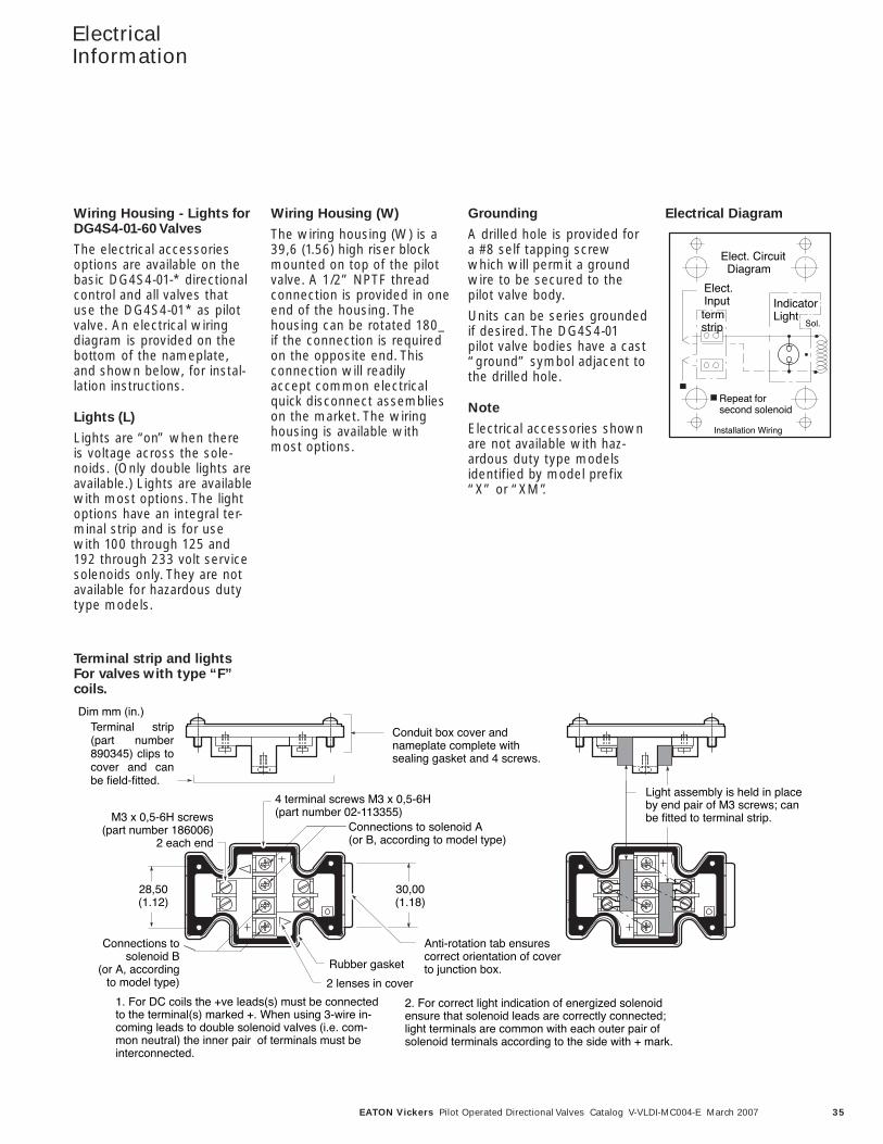
1. For DC coils the +ve leads(s) must be connectedto the terminal(s) marked +. When using 3-wire in-coming leads to double solenoid valves (i.e. com-mon neutral) the inner pair of terminals must beinterconnected.
2. For correct light indication of energized solenoidensure that solenoid leads are correctly connected;light terminals are common with each outer pair of solenoid terminals according to the side with + mark.
Wiring Housing - Lights forDG4S4-01-60 Valves
The electrical accessoriesoptions are available on thebasic DG4S4-01-* directionalcontrol and all valves thatuse the DG4S4-01* as pilotvalve. An electrical wiringdiagram is provided on thebottom of the nameplate,and shown below, for instal-lation instructions.
Lights (L)
Lights are “on” when thereis voltage across the sole-noids. (Only double lights areavailable.) Lights are availablewith most options. The lightoptions have an integral ter-minal strip and is for usewith 100 through 125 and192 through 233 volt servicesolenoids only. They are notavailable for hazardous dutytype models.
Wiring Housing (W)
The wiring housing (W) is a39,6 (1.56) high riser blockmounted on top of the pilotvalve. A 1/2” NPTF threadconnection is provided in oneend of the housing. Thehousing can be rotated 180_if the connection is requiredon the opposite end. Thisconnection will readilyaccept common electricalquick disconnect assemblieson the market. The wiringhousing is available withmost options.
Grounding
A drilled hole is provided fora #8 self tapping screwwhich will permit a groundwire to be secured to thepilot valve body.
Units can be series groundedif desired. The DG4S4-01pilot valve bodies have a cast“ground” symbol adjacent tothe drilled hole.
Note
Electrical accessories shownare not available with haz-ardous duty type modelsidentified by model prefix“X” or “XM”.
Electrical Diagram
Terminal strip and lightsFor valves with type “F”coils.
Elect. Circuit Diagram
Repeat forsecond solenoid
Installation Wiring
Indicator Light
Sol.
Elect.Inputtermstrip
36 EATON Vickers Pilot Operated Directional Valves Catalog V-VLDI-MC004-E March 2007
ElectricalInformation
68,65(2.71)
16,00(0.62)
0.875-16UN-2A thd.
Warning tag:“Electrical power must be disconnected before removing or replacing electrical plug.“
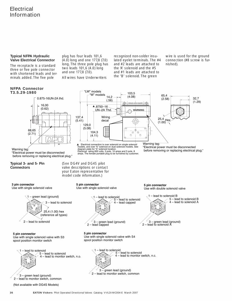
NFPA Connector T3.5.29-1980
32,7(1.29)
137,4(5.41)
129,0(5.08)
104,3(4.11)
“W” models“LW” models
.8750–16UN–2A Thd.
Wiringdecal
14,2(.56)
65,4(2.58)
25,4(1.00)
Hex
103,5(4.08)
Warning tag:“Electrical power must be disconnected before removing or replacing electrical plug.“
Electrical connection is over solenoid on single solenoidmodels, and over “b” solenoid on dual solenoid models. Seediagram plate for “b” solenoid location.Electrical rating 600 volts, 3 pole, 10 amps and 5 pole, 8amps. The female portable plug to be furnished by customer.
Typical NFPA HydraulicValve Electrical Connector
The receptacle is a standardthree or five pole connectorwith shortened leads and ter-minals added. The five pole
plug has four leads 101,6(4.0) long and one 177,8 (7.0)long. The three pole plug hastwo leads 101,6 (4.0) longand one 177,8 (7.0).
All wires have Underwriters
recognized non-solder insu-lated eyelet terminals. The #4and #2 leads are attached tothe ‘A’ solenoid and the #5and #1 leads are attached tothe ‘B’ solenoid. The green
wire is used for the groundconnection (#8 screw is fur-nished).
NFPA Connector T3.5.29-1980
3 pin connectorUse with single solenoid valve
5 pin connectorUse with single solenoid valve with S3spool position monitor switch
5 pin connectorUse with single solenoid valve
41
2 3
54 – lead to solenoid A
1 – lead to solenoid B
3 – green lead (ground)
5 – lead to solenoid B
2 – lead to solenoid A
12
325,4 (1.00) hex
(reference all types)
3 – lead to solenoid
1 – green lead (ground)
2 – lead to solenoid
41
2 3
5 4 – lead to monitor switch, n.o.
1 – lead to solenoid
3 – green lead (ground)
5 – lead to solenoid
2 – lead to monitor switch, common
41
2 3
5
1 – lead to solenoid
3 – green lead (ground)
5 – lead to solenoid
41
2 3
54 – lead capped
1 – lead to solenoid
3 – green lead (ground)
5 – lead to solenoid
2 – lead capped
5 pin connectorUse with double solenoid valve
5 pin connectorUse with single solenoid valve with S4spool position monitor switch
4 – lead to monitor switch, n.c.
2 – lead to monitor switch, common
(Not available with DG4S Models)
Typical 3- and 5- PinConnectors
(See DG4V and DG4S pilotvalve descriptions or contactyour Eaton representative formodel code information.)
37EATON Vickers Pilot Operated Directional Valves Catalog V-VLDI-MC004-E March 2007
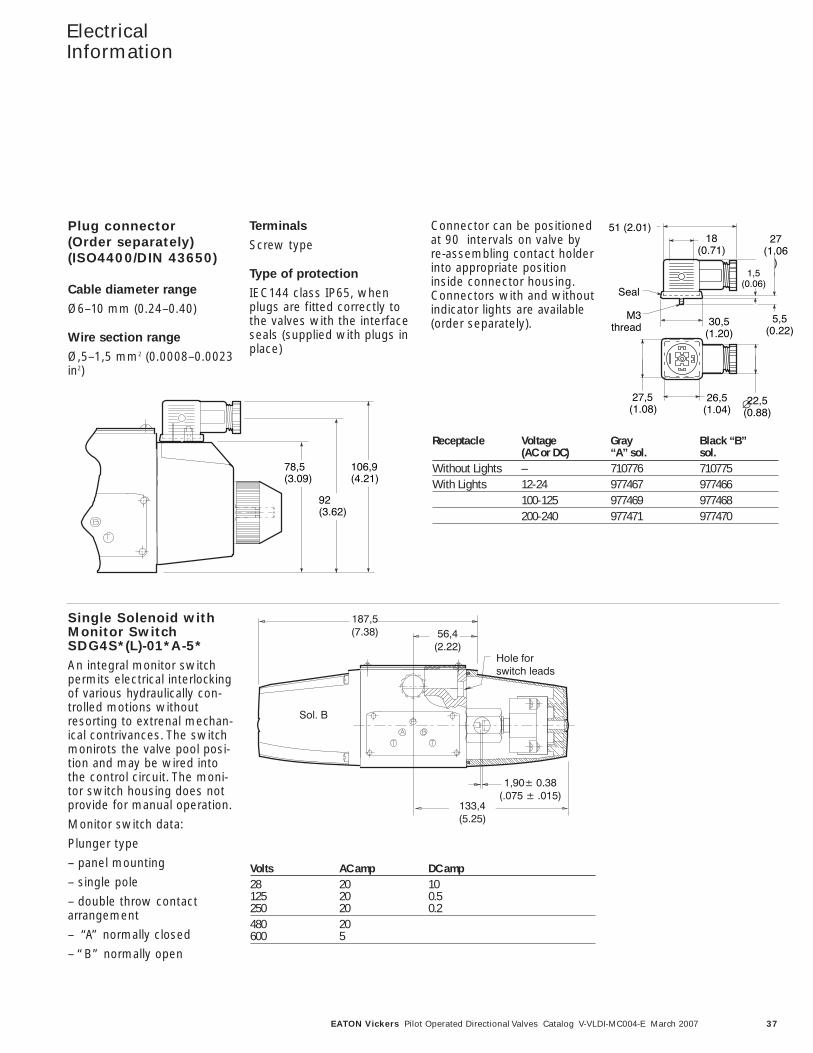
Plug connector(Order separately)(ISO4400/DIN 43650)
Cable diameter range
Ø6–10 mm (0.24–0.40)
Wire section range
Ø,5–1,5 mm2 (0.0008–0.0023in2)
Terminals
Screw type
Type of protection
IEC144 class IP65, whenplugs are fitted correctly tothe valves with the interfaceseals (supplied with plugs inplace)
Connector can be positionedat 90 intervals on valve byre-assembling contact holderinto appropriate positioninside connector housing.Connectors with and withoutindicator lights are available(order separately).
ElectricalInformation
78,5(3.09)
92(3.62)
106,9(4.21)
Seal
51 (2.01)27
(1.06)
22,5(0.88)
M3thread
5,5(0.22)
1,5(0.06)
30,5(1.20)
26,5(1.04)
18(0.71)
∅ 27,5(1.08)
Receptacle Voltage Gray Black “B”(AC or DC) “A” sol. sol.
Without Lights – 710776 710775With Lights 12-24 977467 977466
100-125 977469 977468200-240 977471 977470
Single Solenoid withMonitor SwitchSDG4S*(L)-01*A-5*An integral monitor switchpermits electrical interlockingof various hydraulically con-trolled motions withoutresorting to extrenal mechan-ical contrivances. The switchmonirots the valve pool posi-tion and may be wired intothe control circuit. The moni-tor switch housing does notprovide for manual operation.
Monitor switch data:
Plunger type
– panel mounting
– single pole
– double throw contactarrangement
– “A” normally closed
– “B” normally open
Volts AC amp DC amp28 20 10125 20 0.5250 20 0.2480 20600 5
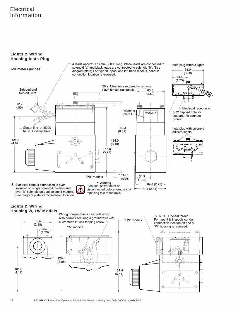
38 EATON Vickers Pilot Operated Directional Valves Catalog V-VLDI-MC004-E March 2007
ElectricalInformation
Lights & Wiring HousingInsta-Plug
Millimeters (inches)
Electrical conduit connection is oversolenoid on single solenoid models, andover “b” solenoid on dual solenoid models.See diagram plate for “b” solenoid location.
WarningElectrical power must bedisconnected before removing orreplacing this receptacle.
4 leads approx. 178 mm (7.00”) long. White leads are connected tosolenoid “a” and black leads are connected to solenoid “b”. (Seediagram plate) For type “8” spool and left hand models, conduitconnection location is reversed.
Clearance required to removefemale receptacle
20,2(.80)Stripped and
twisted wire
12,7(.50)
Center line of .5000 NPTF Dryseal thread
126,2(4.97)
“PB” models “PB-L”models
63,5(2.50)
34,9(1.38)
Warning plate G
160,3(6.31)
154,9(6.10)
146,8(5.77)
Insta-plug with solenoidindicator lights
Electrical receptacle8-32 Tapped hole for customer to connectground
88,9(3.50)
44,4(1.75)
Insta-plug without lights
71,4 (2.81)
69,8 (2.75)
Lights & Wiring HousingW, LW ModelsMillimeters (inches)
32,7(1.29)
65,4(2.58)
104,3(4.11)
137,4(5.41)
129,0(5.08)
.50 NPTF Dryseal thread. For type 4 & 8 spools conduitconnection location on end of“W” housing is reversed.
“LW” models
“W” models
Wiring housing has a cast hole whichalso permits securing a ground wire withcustomerʼs #8 self tapping screw.
Lights & WiringHousing Insta-Plug
Lights & WiringHousing W, LW Models
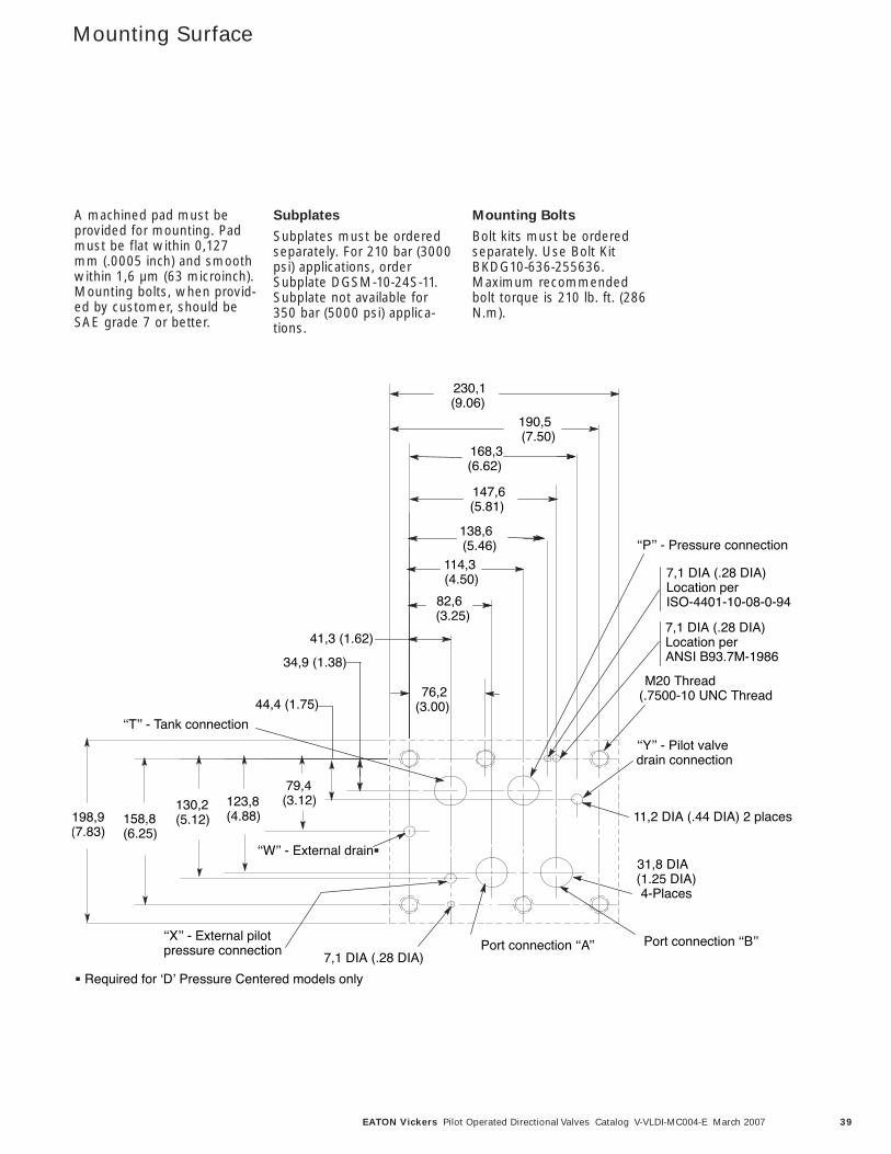
39EATON Vickers Pilot Operated Directional Valves Catalog V-VLDI-MC004-E March 2007
Mounting Surface
198,9(7.83)
158,8(6.25)
130,2(5.12)
123,8(4.88)
79,4 (3.12)
82,6(3.25)
138,6(5.46)
230,1(9.06)
190,5(7.50)
168,3(6.62)
147,6(5.81)
114,3 (4.50)
76,2(3.00)
M20 Thread (.7500-10 UNC Thread
31,8 DIA(1.25 DIA)4-Places
ʻʻXʼʼ - External pilot pressure connection Port connection ʻʻAʼʼ Port connection ʻʻBʼʼ
ʻʻPʼʼ - Pressure connection
ʻʻTʼʼ - Tank connection
ʻʻYʼʼ - Pilot valve drain connection
ʻʻWʼʼ - External drain
7,1 DIA (.28 DIA)Location perISO-4401-10-08-0-94
11,2 DIA (.44 DIA) 2 places
41,3 (1.62)
34,9 (1.38)
44,4 (1.75)
Required for ʻDʼ Pressure Centered models only
7,1 DIA (.28 DIA)
7,1 DIA (.28 DIA)Location perANSI B93.7M-1986
A machined pad must beprovided for mounting. Padmust be flat within 0,127mm (.0005 inch) and smoothwithin 1,6 µm (63 microinch).Mounting bolts, when provid-ed by customer, should beSAE grade 7 or better.
Subplates
Subplates must be orderedseparately. For 210 bar (3000psi) applications, orderSubplate DGSM-10-24S-11.Subplate not available for350 bar (5000 psi) applica-tions.
Mounting Bolts
Bolt kits must be orderedseparately. Use Bolt KitBKDG10-636-255636.Maximum recommendedbolt torque is 210 lb. ft. (286N.m).
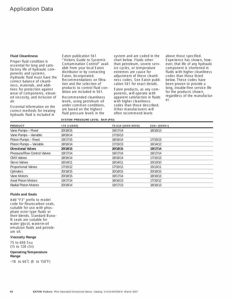
40 EATON Vickers Pilot Operated Directional Valves Catalog V-VLDI-MC004-E March 2007
Application Data
Fluid Cleanliness
Proper fluid condition isessential for long and satis-factory life of hydraulic com-ponents and systems.Hydraulic fluid must have thecorrect balance of cleanli-ness, materials, and addi-tives for protection againstwear of components, elevat-ed viscosity, and inclusion ofair.
Essential information on thecorrect methods for treatinghydraulic fluid is included in
Eaton publication 561“Vickers Guide to SystemicContamination Control” avail-able from your local Eatondistributor or by contactingEaton, Incorporated.Recommendations on filtra-tion and the selection ofproducts to control fluid con-dition are included in 561.
Recommended cleanlinesslevels, using petroleum oilunder common conditions,are based on the highestfluid pressure levels in the
system and are coded in thechart below. Fluids otherthan petroleum, severe serv-ice cycles, or temperatureextremes are cause foradjustment of these cleanli-ness codes. See Eaton publi-cation 561 for exact details.
Eaton products, as any com-ponents, will operate withapparent satisfaction in fluidswith higher cleanlinesscodes than those described.Other manufacturers willoften recommend levels
above those specified.Experience has shown, how-ever, that life of any hydrauliccomponent is shortened influids with higher cleanlinesscodes than those listedbelow. These codes havebeen proven to provide along, trouble-free service lifefor the products shown,regardless of the manufactur-er.
SYSTEM PRESSURE LEVEL BAR (PSI)
PRODUCT <70 (<1000) 70-210 (1000-3000) 210+ (3000+)
Vane Pumps – FIxed 20/18/15 19/17/14 18/16/13Vane Pumps – Variable 18/16/14 17/15/13Piston Pumps – Fixed 19/17/15 18/16/14 17/15/13Piston Pumps – Variable 18/16/14 17/15/13 16/14/12Directional Valves 20/18/15 20/18/15 19/17/14Pressure/Flow Control Valves 19/17/14 19/17/14 19/17/14CMX Valves 18/16/14 18/16/14 17/15/13Servo Valves 16/14/11 16/14/11 15/13/10Proportional Valves 17/15/12 17/15/12 15/13/11Cylinders 20/18/15 20/18/15 20/18/15Vane Motors 20/18/15 19/17/14 18/16/13Axial Piston Motors 19/17/14 18/16/13 17/15/12Radial Piston Motors 20/18/14 19/17/13 18/16/13
Fluids and Seals
Add ‘‘F3’’ prefix to modelcode for flourocarbon seals,suitable for use with phos-phate ester type fluids ortheir blends. Standard Buna–N seals are suitable forwater glycol, water-in-oilemulsion fluids and petrole-um oil.
Viscosity Range
75 to 600 Ssu (15 to 128 cSt)
Operating Temperature
Range
–18 to 66˚C (0 to 150˚F)
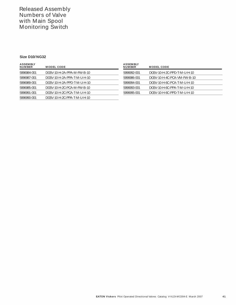
41EATON Vickers Pilot Operated Directional Valves Catalog V-VLDI-MC004-E March 2007
Released AssemblyNumbers of Valvewith Main SpoolMonitoring Switch
5996984-001 DG5V-10-H-2A-PPA-M-FW-B-105996987-001 DG5V-10-H-2A-PPA-T-M-U-H-105996989-001 DG5V-10-H-2A-PPD-T-M-U-H-105996985-001 DG5V-10-H-2C-PCA-M-FW-B-105996991-001 DG5V-10-H-2C-PCA-T-M-U-H-105996990-001 DG5V-10-H-2C-PPA-T-M-U-H-10
5996992-001 DG5V-10-H-2C-PPD-T-M-U-H-105996986-001 DG5V-10-H-4C-PCA-VM-FW-B-105996994-001 DG5V-10-H-6C-PCA-T-M-U-H-105996993-001 DG5V-10-H-6C-PPA-T-M-U-H-105996995-001 DG5V-10-H-6C-PPD-T-M-U-H-10
ASSEMBLY NUMBER MODEL CODE
ASSEMBLY NUMBER MODEL CODE
Size D10/NG32

© 2007 Eaton CorporationAll Rights Reserved Printed in USADocument No. V-VLDI-MC004-ESupercedes 5007.01/EN/0197/AMarch 2007
Eaton14615 Lone Oak RoadEden Prairie, MN 55344USATel: 952 937-9800Fax: 952 974-7722www.hydraulics.eaton.com
EatonDr.-Reckeweg-Str. 1D-76532 Baden-BadenGermanyTel: (49) 7221 682-0Fax: (49) 7221 682-788
Eaton20 Rosamond RoadFootscrayVictoria 3011AustraliaTel: (61) 3 9319 8222Fax: (61) 3 9318 5714