Embed Size (px)
Citation preview
−1− WK 493 180
WK493 180
04. 2001r
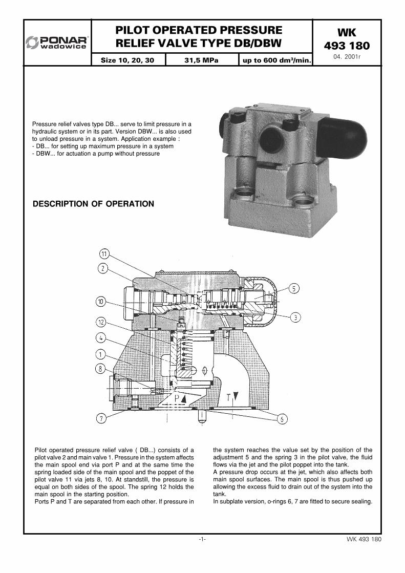
PILOT OPERATED PRESSURE RELIEF VALVE TYPE DB/DBW
DESCRIPTION OF OPERATION
Pressure relief valves type DB... serve to limit pressure in ahydraulic system or in its part. Version DBW... is also usedto unload pressure in a system. Application example :- DB... for setting up maximum pressure in a system- DBW... for actuation a pump without pressure
the system reaches the value set by the position of theadjustment 5 and the spring 3 in the pilot valve, the fluidflows via the jet and the pilot poppet into the tank.A pressure drop occurs at the jet, which also affects bothmain spool surfaces. The main spool is thus pushed upallowing the excess fluid to drain out of the system into thetank.In subplate version, o-rings 6, 7 are fitted to secure sealing.
Pilot operated pressure relief valve ( DB...) consists of apilot valve 2 and main valve 1. Pressure in the system affectsthe main spool end via port P and at the same time thespring loaded side of the main spool and the poppet of thepilot valve 11 via jets 8, 10. At standstill, the pressure isequal on both sides of the spool. The spring 12 holds themain spool in the starting position.Ports P and T are separated from each other. If pressure in
Size 10, 20, 30 31,5 MPa up to 600 dm3/min.
− 2 −WK 493 180
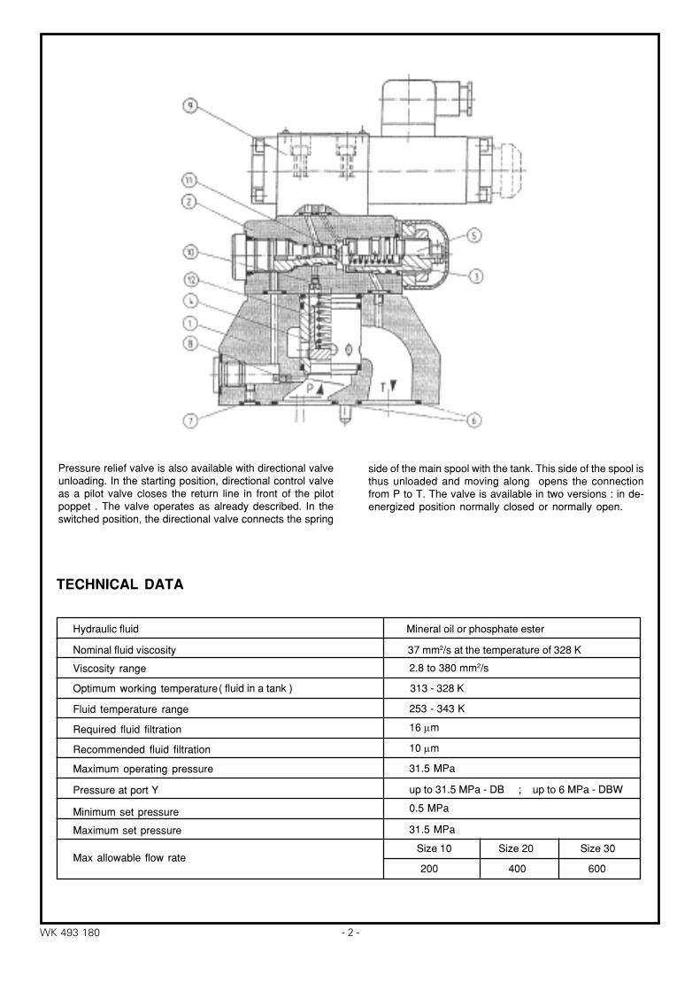
Pressure relief valve is also available with directional valveunloading. In the starting position, directional control valveas a pilot valve closes the return line in front of the pilotpoppet . The valve operates as already described. In theswitched position, the directional valve connects the spring
side of the main spool with the tank. This side of the spool isthus unloaded and moving along opens the connectionfrom P to T. The valve is available in two versions : in de-energized position normally closed or normally open.
Hydraulic fluid Mineral oil or phosphate ester
Nominal fluid viscosity 37 mm2/s at the temperature of 328 K
Viscosity range
Optimum working temperature
Fluid temperature range
Required fluid filtration
Recommended fluid filtration
2.8 to 380 mm2/s
( fluid in a tank ) 313 - 328 K
253 - 343 K
16 µm
10 µm
Maximum operating pressure
Pressure at port Y up to 31.5 MPa - DB ; up to 6 MPa - DBW
Minimum set pressure
Maximum set pressure
0.5 MPa
31.5 MPa
Max allowable flow rateSize 10 Size 20 Size 30
31.5 MPa
TECHNICAL DATA
200 400 600
−3− WK 493 180
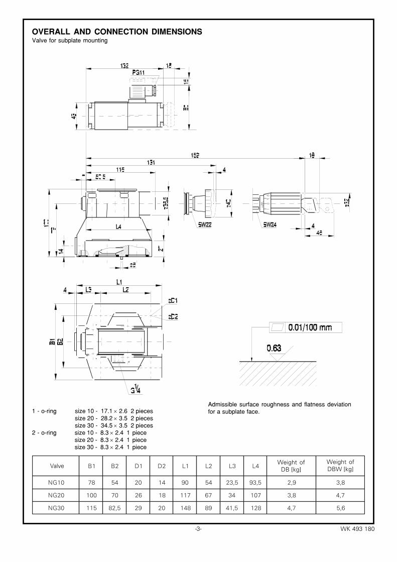
rówaZ 1B 2B 1D 2D 1L 2L 3L 4LBDasaM
)gk(WBDasaM
)gk(
01GN 87 45 02 41 09 45 5,32 5,39 9,2 8,3
02GN 001 07 62 81 711 76 43 701 8,3 7,4
03GN 511 5,28 92 02 841 98 5,14 821 7,4 6,5
OVERALL AND CONNECTION DIMENSIONSValve for subplate mounting
1 - o-ring size 10 - 17.1 × 2.6 2 pieces size 20 - 28.2 × 3.5 2 pieces size 30 - 34.5 × 3.5 2 pieces
2 - o-ring size 10 - 8.3 × 2.4 1 piece size 20 - 8.3 × 2.4 1 piece size 30 - 8.3 × 2.4 1 piece
Admissible surface roughness and flatness deviationfor a subplate face.
Weight ofDB [kg]
Weight ofDBW [kg]Valve
− 4 −WK 493 180
X
12
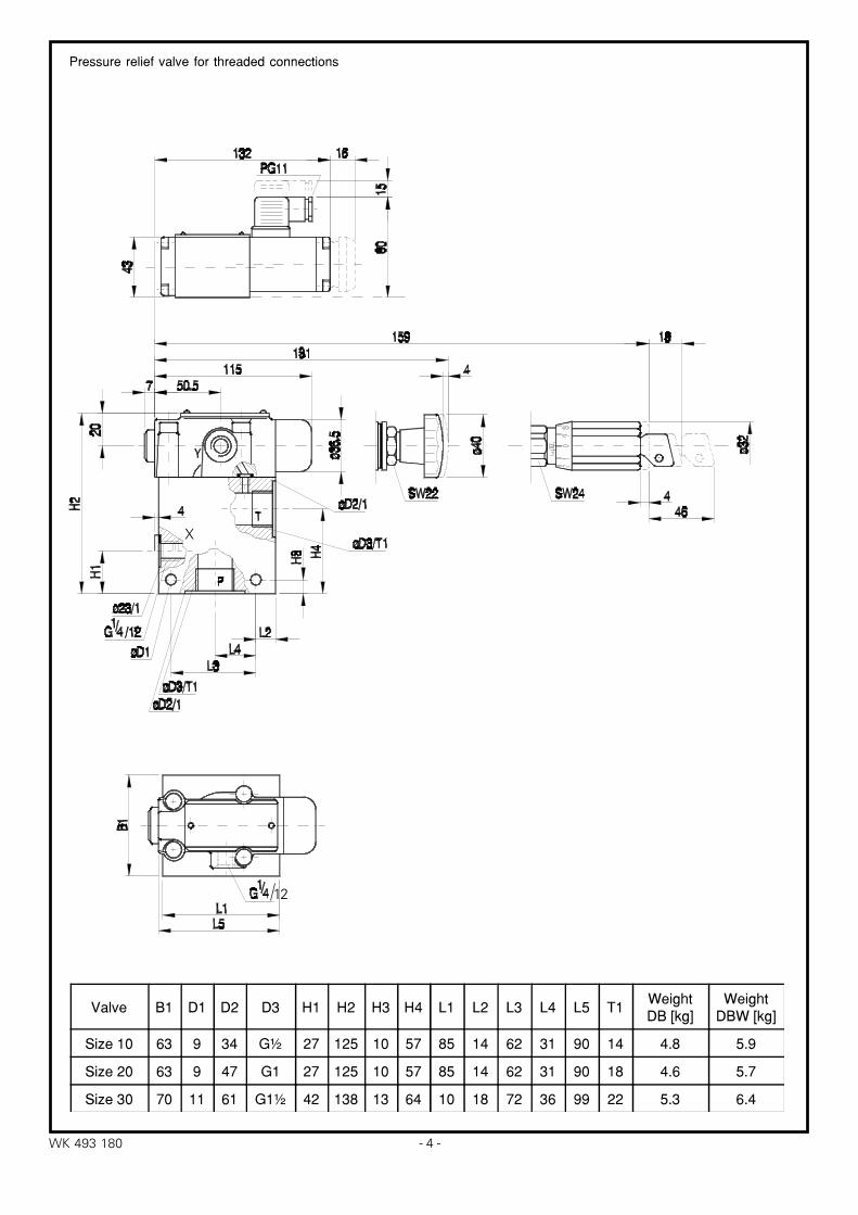
Pressure relief valve for threaded connections
Valve B1 D1 D2 D3 H1 H2 H3 H4
Size 10 63 9 34 G½ 27 125 10 57
Size 20 63 9 47 G1 27 125 10 57
Size 30 70 11 61 G1½ 42 138 13 64
L1 L2 L3 L4 L5 T1WeightDB [kg]
WeightDBW [kg]
85 14 62 31 90 14 4.8 5.9
85 14 62 31 90 18 4.6 5.7
10 18 72 36 99 22 5.3 6.4
−5− WK 493 180
12
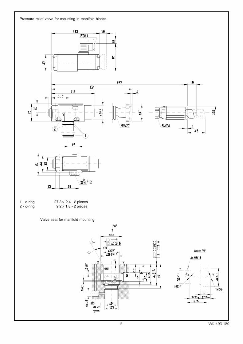
Pressure relief valve for mounting in manifold blocks.
1 - o-ring 27.3 × 2.4 - 2 pieces2 - o-ring 9.2 × 1.8 - 2 pieces
Valve seat for manifold mounting
− 6 −WK 493 180
0 50
1,0
0,5
1,5
2,0
2,5
100 150 200Q (dm /min)
p (M
Pa)
30 50
10
20
30
100 150 200Q (dm /min)
p (M
Pa)
3
Ciœnienie robocze w zale¿noœci od przep³ywu dla NG 10 Najni¿sze nastawiane ciœnienie w zale¿noœci od przep³ywu dla NG 10
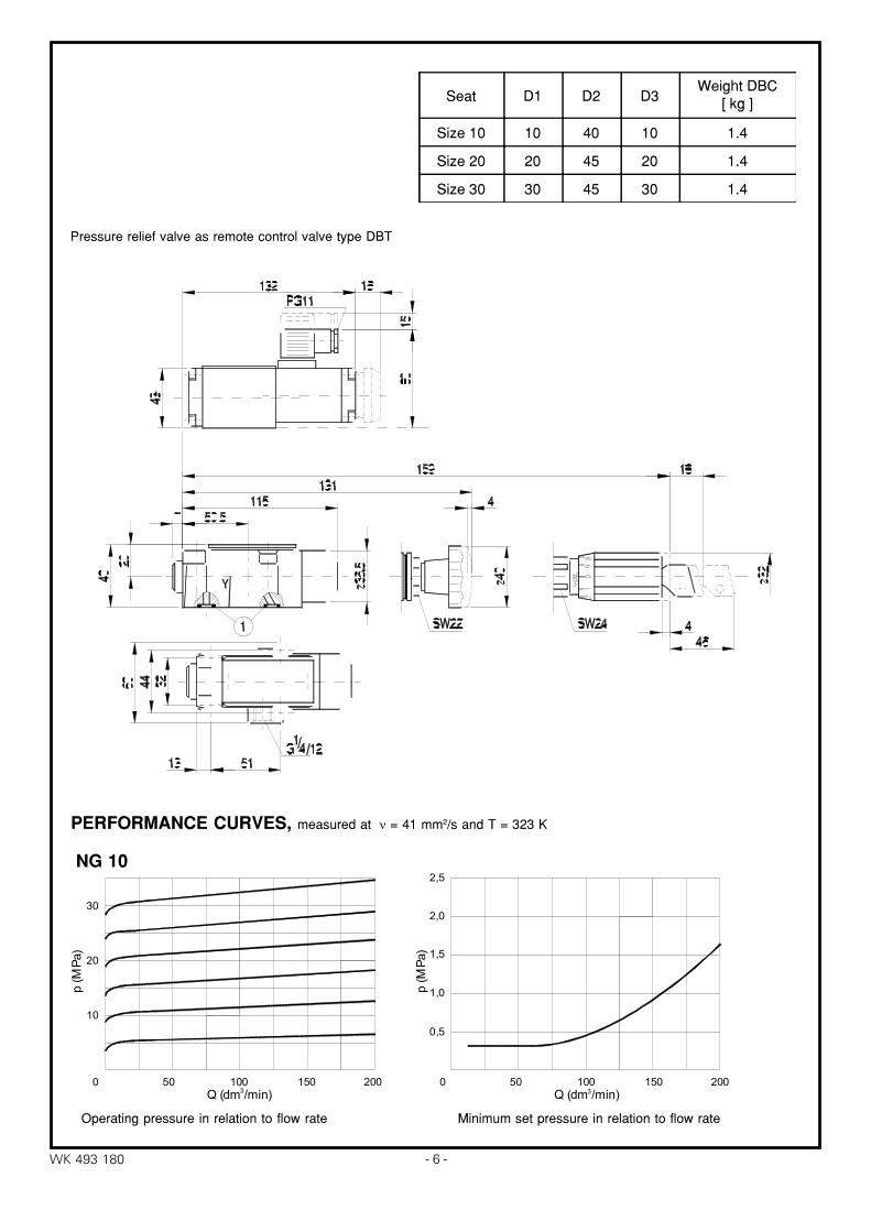
Pressure relief valve as remote control valve type DBT
NG 10
PERFORMANCE CURVES, measured at ν = 41 mm2/s and T = 323 K
Seat D1 D2 D3Weight DBC
[ kg ]
Size 10 10 40 10 1.4
Size 20 20 45 20 1.4
Size 30 30 45 30 1.4
Operating pressure in relation to flow rate Minimum set pressure in relation to flow rate
−7− WK 493 180
0 150
10
20
30
300 450 600Q (dm /min)
p (M
Pa)
0 150
1
2
3
4
300 450 600Q (dm /min)
p (M
Pa)
3 3
0 100
10
20
30
200 300 400Q (dm /min)
p (M
Pa)
0 100
0,5
1,0
1,5
2,0
200 300 400Q (dm /min)
p (M
Pa)
3 3
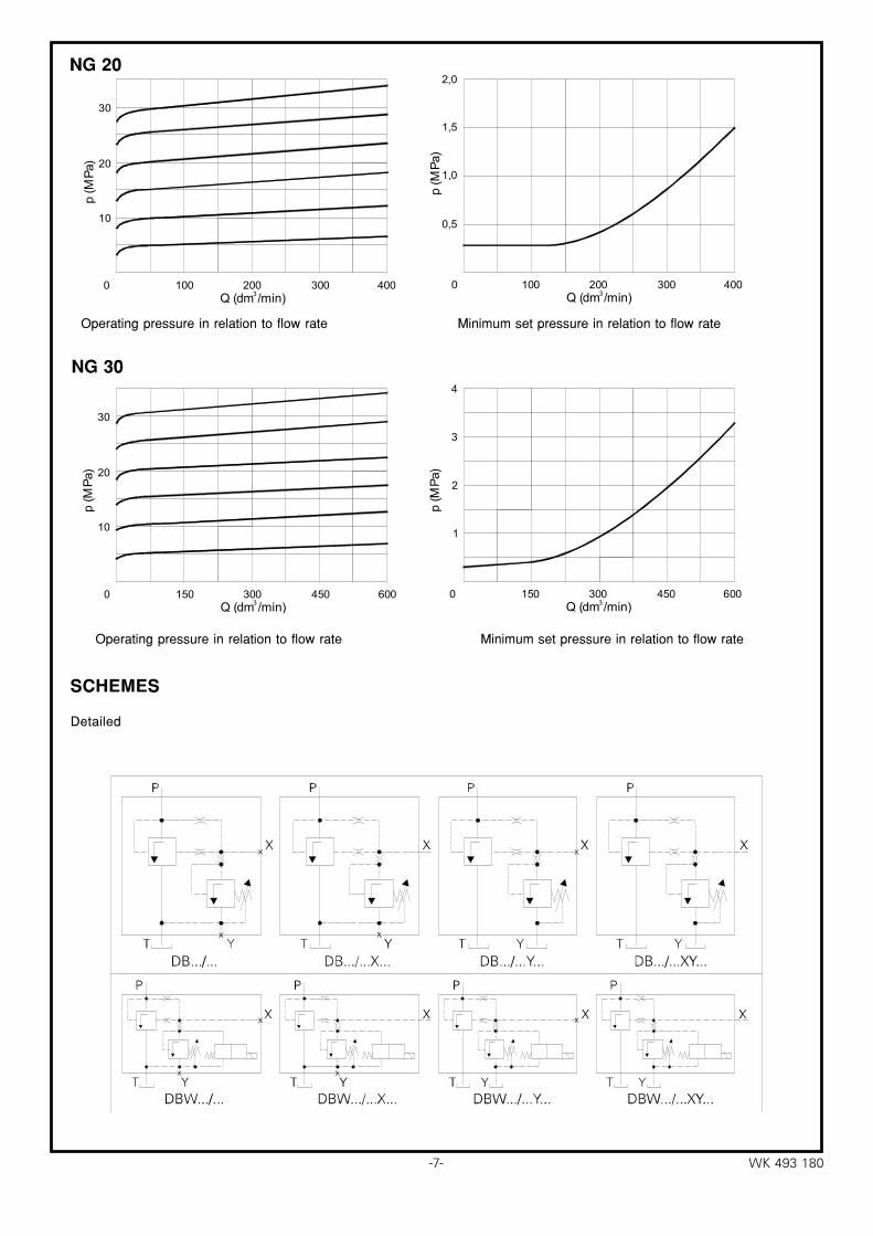
Ciœnienie robocze w zale¿noœci od przep³ywu dla NG 20
Ciœnienie robocze w zale¿noœci od przep³ywu dla NG 30
Najni¿sze ciœnienie w zale¿noœci od przep³ywu dla NG 20nastawiane
Najni¿sze ciœnienie w zale¿noœci od przep³ywu dla NG 30nastawiane
SCHEMES
Detailed
Operating pressure in relation to flow rate Minimum set pressure in relation to flow rate
Operating pressure in relation to flow rate Minimum set pressure in relation to flow rate
NG 20
NG 30
− 8 −WK 493 180
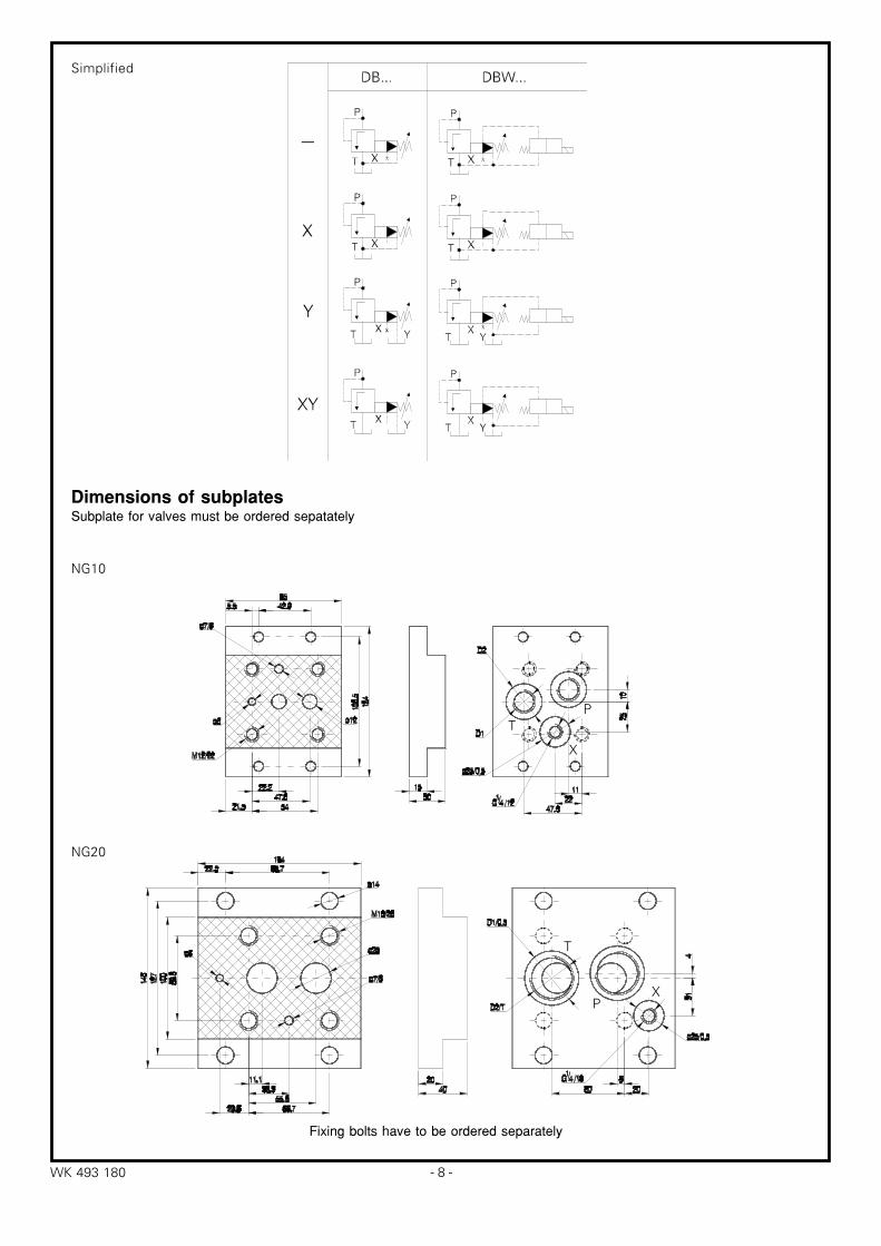
NG10
NG20
TP
X
T
PX
Dimensions of subplatesSubplate for valves must be ordered sepatately
Fixing bolts have to be ordered separately
Simplified
−9− WK 493 180
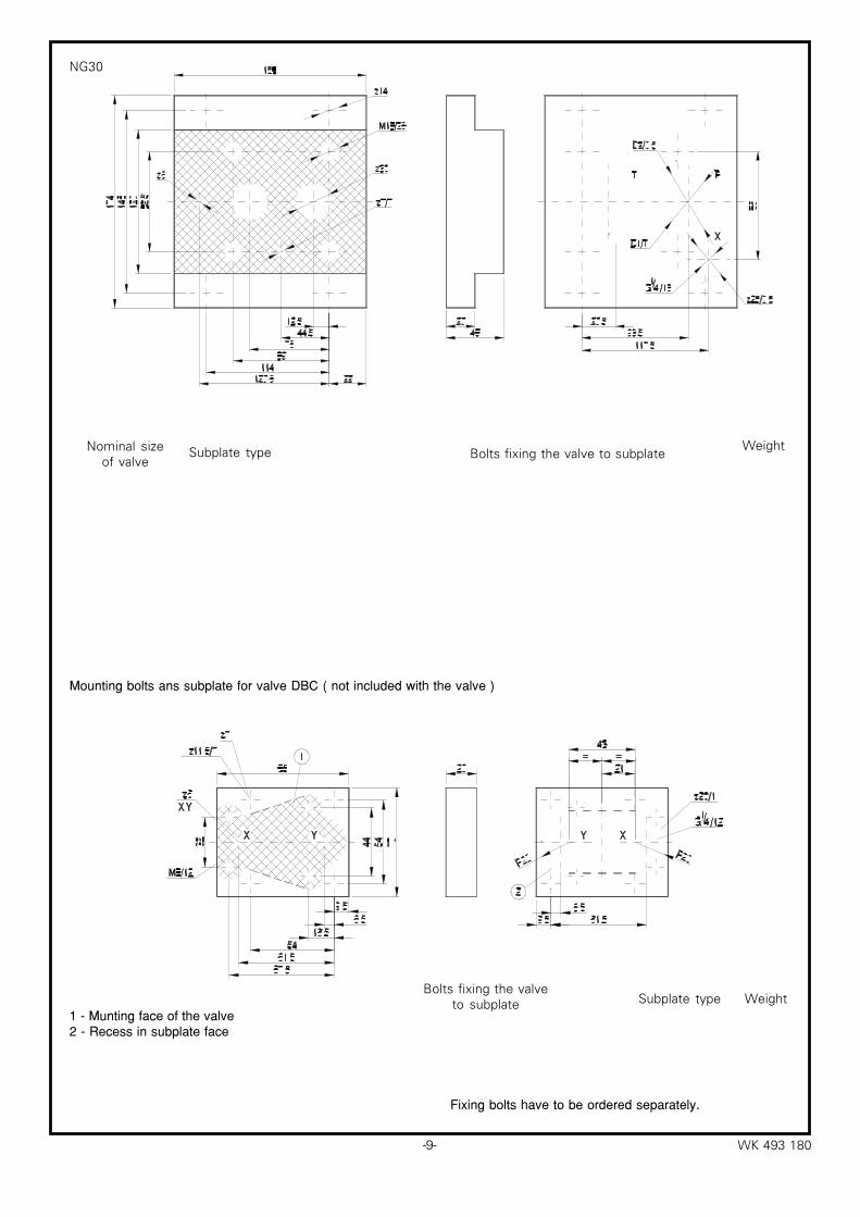
NG30
1 - Munting face of the valve2 - Recess in subplate face
Fixing bolts have to be ordered separately.
Mounting bolts ans subplate for valve DBC ( not included with the valve )
Bolts fixing the valveto subplate Subplate type Weight
Bolts fixing the valve to subplateSubplate type WeightNominal sizeof valve

− 10 −WK 493 180
DB
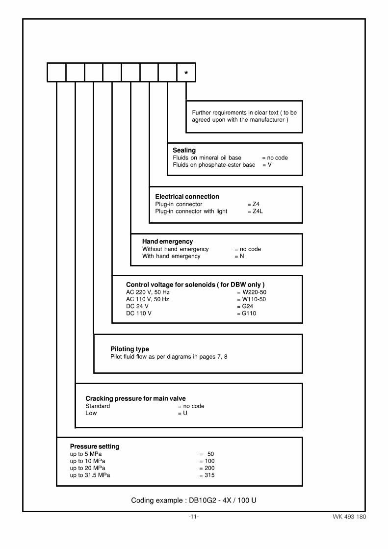
HOW TO ORDEROrders coded in the way showed below should be forwarded to the manufacturer.
⁄⁄⁄⁄⁄
VersionWithout unloading - no codeWith unloading - W
TypeComplete valve - no codePilot valve with main spool - C( for sizes 10 and 30 only )Pilot valvewithout main spool - C( do not quote nominal size )Pilot valve of remote control - T( do not quote nominal size )
Nominal sizeSize 10 = 10Size 20 = 20Size 30 = 30
Directional control valve ( for DBW only )In de-energized position closed = AIn de-energized position open = B
Mounting methodFor subplate mounting = no codeFor threaded connection = G
AdjustmentHandknob = 1Set screw with internal hexagon = 2Lockable handknob = 3
Series number4X =4X( 40 - 49 ) - installation and connection dimensions remain unchanged
Note: Adjustment 1 and 3 not available for valve version with unloading W.
−11− WK 493 180
Coding example : DB10G2 - 4X / 100 U
Pressure settingup to 5 MPa = 50up to 10 MPa = 100up to 20 MPa = 200up to 31.5 MPa = 315
Cracking pressure for main valveStandard = no codeLow = U
Piloting typePilot fluid flow as per diagrams in pages 7, 8
Control voltage for solenoids ( for DBW only )AC 220 V, 50 Hz = W220-50AC 110 V, 50 Hz = W110-50DC 24 V = G24DC 110 V = G110
Hand emergencyWithout hand emergency = no codeWith hand emergency = N
Electrical connectionPlug-in connector = Z4Plug-in connector with light = Z4L
SealingFluids on mineral oil base = no codeFluids on phosphate-ester base = V
Further requirements in clear text ( to beagreed upon with the manufacturer )
*

−12−WK 493 180
![· chwytak do bel max 2100mm bale gripper max max pyiiohob max zakresrozpiÇtoŠci do [mm] masa [kg] silownik actuator udŽwig [kg] lifting [kg] 800 udŽwig [kg] lifting 900 range](https://img.pdfslide.net/doc/110x75/5c76c97f09d3f2b0618bfaf0/-chwytak-do-bel-max-2100mm-bale-gripper-max-max-pyiiohob-max-zakresrozpictosci.jpg)


![PILOT OPERATED PRESSURE WK RELIEF VALVE TYPE DB/DBW … predohranitelnij... · DBW [kg] Valve. WK 460 860 − 4 − Pressure relief valve for threaded connections Valve B1 D1 D2 D3](https://img.pdfslide.net/doc/110x75/5f622f30b4c2be1ab9601042/pilot-operated-pressure-wk-relief-valve-type-dbdbw-predohranitelnij-dbw-kg.jpg)