Embed Size (px)
Citation preview
smarT.NC
Pilot
NC Software
340 490-xx
340 491-xx
340 492-xx
340 493-xx
340 494-xx
English (en)
11/2004
iTNC 530

3
Th
e s
ma
rT.N
C P
ilo
t
The smarT.NC Pilot
... is your concise programming guide for the new smarT.NC operating mode of the iTNC 530. For more comprehensive information on programming and operating the iTNC 530, refer to the User’s Manual.
Symbols in the Pilot
Certain symbols are used in the Pilot to denote specific types of information:
Control NC software number
iTNC 530 340 490-xx
iTNC 530, export version 340 491-xx
iTNC 530 with Windows 2000 340 492-xx
iTNC 530 with Windows 2000, export version
340 493-xx
iTNC 530 programming station 340 494-xxImportant note
Warning: danger for the user or machine!
The TNC and the machine tool must be prepared by the machine tool builder to perform this function.
4
Co
nte
nts
Contents
The smarT.NC Pilot 3
Fundamentals 5
Defining Machining Operations 22
Defining Machining Positions 95
Defining contours 109
Graphically test and run a UNIT program 117
5
Fu
nd
am
en
tals
Fundamentals
Introduction to smarT.NC
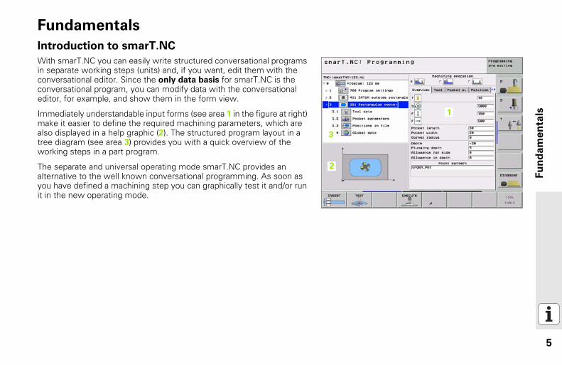
With smarT.NC you can easily write structured conversational programs in separate working steps (units) and, if you want, edit them with the conversational editor. Since the only data basis for smarT.NC is the conversational program, you can modify data with the conversational editor, for example, and show them in the form view.
Immediately understandable input forms (see area 1 in the figure at right) make it easier to define the required machining parameters, which are also displayed in a help graphic (2). The structured program layout in a tree diagram (see area 3) provides you with a quick overview of the working steps in a part program.
The separate and universal operating mode smarT.NC provides an alternative to the well known conversational programming. As soon as you have defined a machining step you can graphically test it and/or run it in the new operating mode.
11
2
13

6
Fu
nd
am
en
tals
Features available with smarT.NCIn the software version available at present, not all TNC functions definable in conversational dialog are also definable with the forms in smarT.NC. We are developing the software to include as many functions as quickly as possible in smarT.NC.
To ensure flexibility, smarT.NC features a conversational unit in which almost any conversational function can be inserted between the working units defined in smarT.NC. Blocks inserted in this way will be shown exactly as they are in the conversational editor.
Programming and execution of drilling cycles (201, 202, 204, 205, 240)Programming and execution of tapping cycles (Cycles 206 and 209)Programming and execution of thread milling cycles (Cycles 26x)Programming and execution of pocket milling cycles (Cycles 25x, Cycle 209)Programming and execution of simple operations (Cycle 232)Programming and execution of contouring cycles (20, 22, 25)Programming and execution of touch probe cycles (all Cycles 4xx)Programming and execution of coordinate transformations through a conversational unit (datum shift, mirroring, rotation, scaling, tilting the working plane with the PLANE function)Graphically supported definition of machining positions (pattern generator)Graphically supported hiding and locking of machining positionsGraphically supported and help-graphic supported definition of contours for use in the contour cyclesContour pocket capable of simply linking pocket and island contours (EasyMode contour formula, roughing)
The following form-based functions are available in the current software.
7
Fu
nd
am
en
tals
Selection of contour programs (.HC files) and machining positions (.PNT files) from the form in a file selection dialog boxStandard file management in the smarT.NC directoryGraphic simulation of machining (test run)Mouse support (also on the single-processor version)
8
Fu
nd
am
en
tals
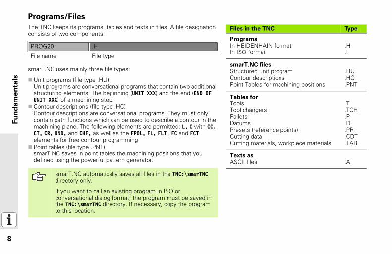
Programs/FilesThe TNC keeps its programs, tables and texts in files. A file designation consists of two components:
smarT.NC uses mainly three file types:
Unit programs (file type .HU)Unit programs are conversational programs that contain two additional structuring elements: The beginning (UNIT XXX) and the end (END OF UNIT XXX) of a machining step.Contour descriptions (file type .HC)Contour descriptions are conversational programs. They must only contain path functions which can be used to describe a contour in the machining plane. The following elements are permitted: L, C with CC, CT, CR, RND, and CHF, as well as the FPOL, FL, FLT, FC and FCT elements for free contour programmingPoint tables (file type .PNT)smarT.NC saves in point tables the machining positions that you defined using the powerful pattern generator.
Files in the TNC Type
ProgramsIn HEIDENHAIN formatIn ISO format
.H
.I
smarT.NC filesStructured unit programContour descriptionsPoint Tables for machining positions
.HU
.HC
.PNT
Tables forToolsTool changersPalletsDatumsPresets (reference points)Cutting dataCutting materials, workpiece materials
.T
.TCH
.P
.D
.PR
.CDT
.TAB
Texts asASCII files .A
PROG20 .H
File name File type
smarT.NC automatically saves all files in the TNC:\smarTNC directory only.
If you want to call an existing program in ISO or conversational dialog format, the program must be saved in the TNC:\smarTNC directory. If necessary, copy the program to this location.
9
Fu
nd
am
en
tals
Selecting the new operating mode the first time
Select the smarT.NC operating mode: The file manager of the TNC appears.Select one of the available example programs with the arrow keys and press ENTER, orIn order to write a new machining program, press the NEW FILE soft key. smarT.NC opens a pop-up window.Enter the file name without the file type, and confirm with the MM (or INCH) soft key or screen button. smarT.NC creates an .HU program with the selected units of measurement and automatically inserts the program header form.The data for the program header form are mandatory, since they are globally valid for the entire machining program. The default values are specified internally. Change the data if necessary, and save them with the END key.In order to define machining steps, press the EDIT soft key to select the desired machining step.
10
Fu
nd
am
en
tals
File management with smarT.NCAs mentioned previously, smarT.NC differentiates between three file types: unit programs (.HU), contour descriptions (.HC) and point tables (.PNT). These three file types can be selected and edited in the file manager in the smarT.NC operating mode. Contour descriptions and point tables can also be edited if you are currently defining a working unit.
In the current software version, smarT.NC automatically saves all files in the TNC:\smarTNC directory only.
11
Fu
nd
am
en
tals
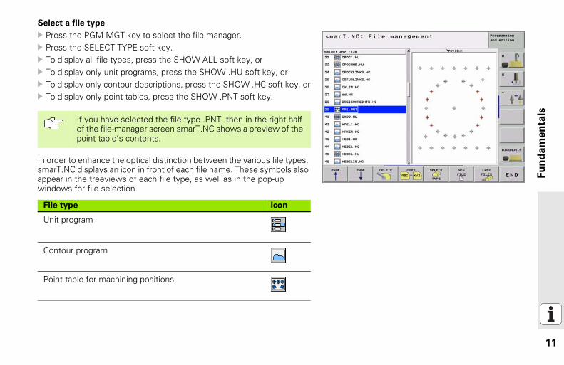
Select a file type
Press the PGM MGT key to select the file manager.Press the SELECT TYPE soft key.To display all file types, press the SHOW ALL soft key, orTo display only unit programs, press the SHOW .HU soft key, orTo display only contour descriptions, press the SHOW .HC soft key, orTo display only point tables, press the SHOW .PNT soft key.
In order to enhance the optical distinction between the various file types, smarT.NC displays an icon in front of each file name. These symbols also appear in the treeviews of each file type, as well as in the pop-up windows for file selection.
If you have selected the file type .PNT, then in the right half of the file-manager screen smarT.NC shows a preview of the point table’s contents.
File type Icon
Unit program
Contour program
Point table for machining positions
12
Fu
nd
am
en
tals
Creating a new filePress the PGM MGT key to select the file manager.Select the file type of the new file, as described earlierPress the NEW FILE soft key. smarT.NC opens a pop-up window.Enter the file name without the file type, and confirm with the MM (or INCH) soft key or screen button. smarT.NC creates a file with the selected units of measurement. In order to cancel the procedure, press the ESC key or the Cancel screen button.
13
Fu
nd
am
en
tals
Copying a file
Press the PGM MGT key to select the file manager.Use the arrow keys to place the highlight on the file you want to copyPress the COPY soft key. smarT.NC opens a pop-up window.Enter the file name of the target file without the file type, and confirm with the ENT key or the OK screen button. smarT.NC copies the contents of the selected file into a new file of the same file type. In order to cancel the procedure, press the ESC key or the Cancel screen button.
Deleting a file
Press the PGM MGT key to select the file manager.Use the arrow keys to place the highlight on the file you want to deletePress the DELETE soft key. smarT.NC opens a pop-up window.In order to delete the selected file, press either the ENT key or the Yes screen button. In order to cancel the delete procedure, press the ESC key or the No screen button.
14
Fu
nd
am
en
tals
Renaming a filePress the PGM MGT key to select the file manager.Use the arrow keys to place the highlight on the file you want to rename.Press the RENAME soft key (second soft-key row). smarT.NC opens a pop-up window.Enter the new file name and confirm your entry with the ENT key or OK screen button. In order to cancel the procedure, press the ESC key or the Cancel screen button.
Selecting one of the last 15 files selected
Press the PGM MGT key to select the file manager.Press the LAST FILES soft key. smarT.NC displays the last 15 files that you selected in the smarT.NC operating mode.Use the arrow keys to place the highlight on the file you want to select.Press the ENT key to select the file.
15
Fu
nd
am
en
tals
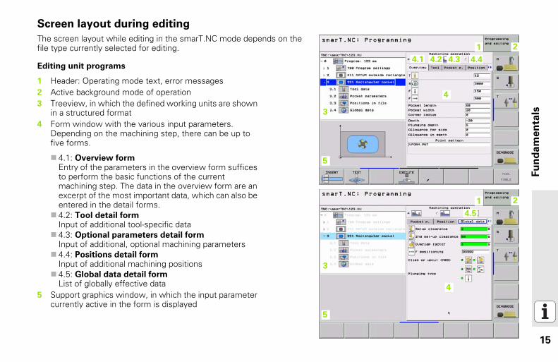
Screen layout during editing
The screen layout while editing in the smarT.NC mode depends on the file type currently selected for editing.
Editing unit programs
11 2
13
14
14.1 14.2 14.3 14.4
15
11 2
13
14
14.5
15
1 Header: Operating mode text, error messages2 Active background mode of operation3 Treeview, in which the defined working units are shown
in a structured format4 Form window with the various input parameters.
Depending on the machining step, there can be up to five forms.
4.1: Overview formEntry of the parameters in the overview form suffices to perform the basic functions of the current machining step. The data in the overview form are an excerpt of the most important data, which can also be entered in the detail forms.4.2: Tool detail formInput of additional tool-specific data4.3: Optional parameters detail formInput of additional, optional machining parameters4.4: Positions detail formInput of additional machining positions4.5: Global data detail formList of globally effective data
5 Support graphics window, in which the input parameter currently active in the form is displayed

16
Fu
nd
am
en
tals
Editing machining positions11 2
13
14
15
16
1 Header: Operating mode text, error messages2 Active background mode of operation3 Treeview, in which the defined working patterns are
shown in a structured format4 Form window with the appropriate input parameters5 Support graphics window, in which the input parameter
currently active is displayed6 Graphics window, in which the programmed machining
positions are show immediately after being saved in the form
17
Fu
nd
am
en
tals
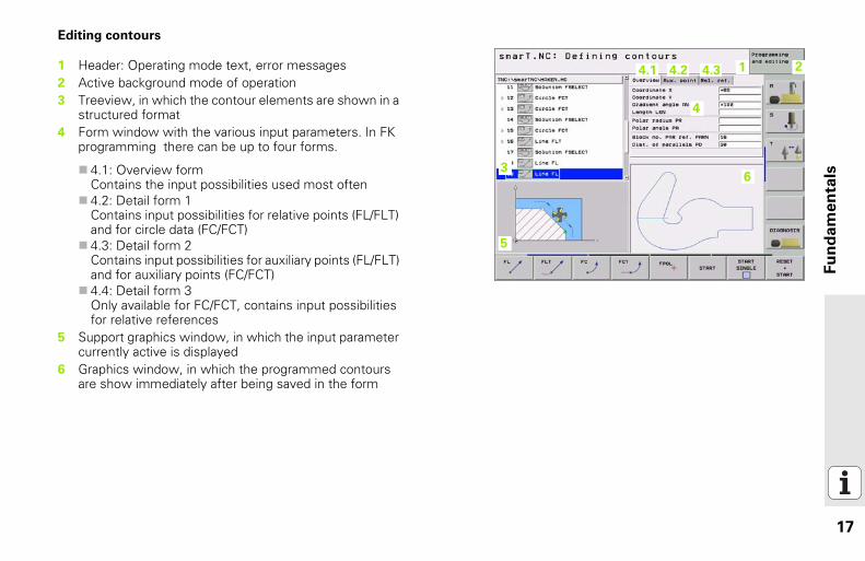
Editing contours
11 2
13
14
14.1 14.2 14.3
15
16
1 Header: Operating mode text, error messages2 Active background mode of operation3 Treeview, in which the contour elements are shown in a
structured format4 Form window with the various input parameters. In FK
programming there can be up to four forms.
4.1: Overview formContains the input possibilities used most often4.2: Detail form 1Contains input possibilities for relative points (FL/FLT) and for circle data (FC/FCT)4.3: Detail form 2Contains input possibilities for auxiliary points (FL/FLT) and for auxiliary points (FC/FCT)4.4: Detail form 3Only available for FC/FCT, contains input possibilities for relative references
5 Support graphics window, in which the input parameter currently active is displayed
6 Graphics window, in which the programmed contours are show immediately after being saved in the form
18
Fu
nd
am
en
tals
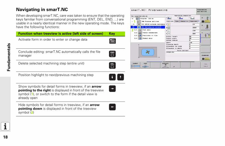
Navigating in smarT.NCWhen developing smarT.NC, care was taken to ensure that the operating keys familiar from conversational programming (ENT, DEL, END, ...) are usable in a nearly identical manner in the new operating mode. The keys have the following functions:
Function when treeview is active (left side of screen) Key
Activate form in order to enter or change data
Conclude editing: smarT.NC automatically calls the file manager
Delete selected machining step (entire unit)
Position highlight to next/previous machining step
Show symbols for detail forms in treeview, if an arrow pointing to the right is displayed in front of the treeview symbol (1), or switch to the form if the detail view is already open
Hide symbols for detail forms in treeview, if an arrow pointing down is displayed in front of the treeview symbol (2)
11
12
19
Fu
nd
am
en
tals
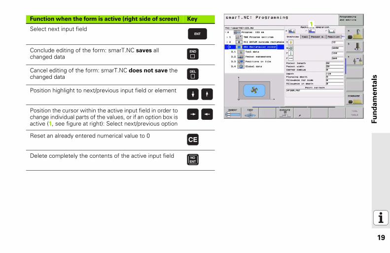
Function when the form is active (right side of screen) Key
Select next input field
Conclude editing of the form: smarT.NC saves all changed data
Cancel editing of the form: smarT.NC does not save the changed data
Position highlight to next/previous input field or element
Position the cursor within the active input field in order to change individual parts of the values, or if an option box is active (1, see figure at right): Select next/previous option
Reset an already entered numerical value to 0
Delete completely the contents of the active input field
11
20
Fu
nd
am
en
tals
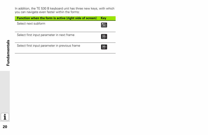
In addition, the TE 530 B keyboard unit has three new keys, with which you can navigate even faster within the forms:Function when the form is active (right side of screen) Key
Select next subform
Select first input parameter in next frame
Select first input parameter in previous frame
21
Fu
nd
am
en
tals
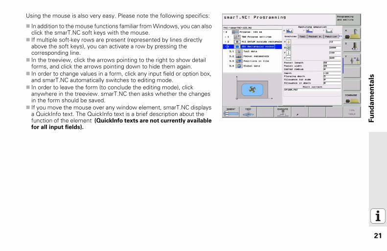
Using the mouse is also very easy. Please note the following specifics:
In addition to the mouse functions familiar from Windows, you can also click the smarT.NC soft keys with the mouse.If multiple soft-key rows are present (represented by lines directly above the soft keys), you can activate a row by pressing the corresponding line.In the treeview, click the arrows pointing to the right to show detail forms, and click the arrows pointing down to hide them again.In order to change values in a form, click any input field or option box, and smarT.NC automatically switches to editing mode.In order to leave the form (to conclude the editing mode), click anywhere in the treeview. smarT.NC then asks whether the changes in the form should be saved.If you move the mouse over any window element, smarT.NC displays a QuickInfo text. The QuickInfo text is a brief description about the function of the element (QuickInfo texts are not currently available for all input fields).
22
Defi
nin
g M
ach
inin
g O
pera
tio
ns
Defining Machining OperationsFundamentals
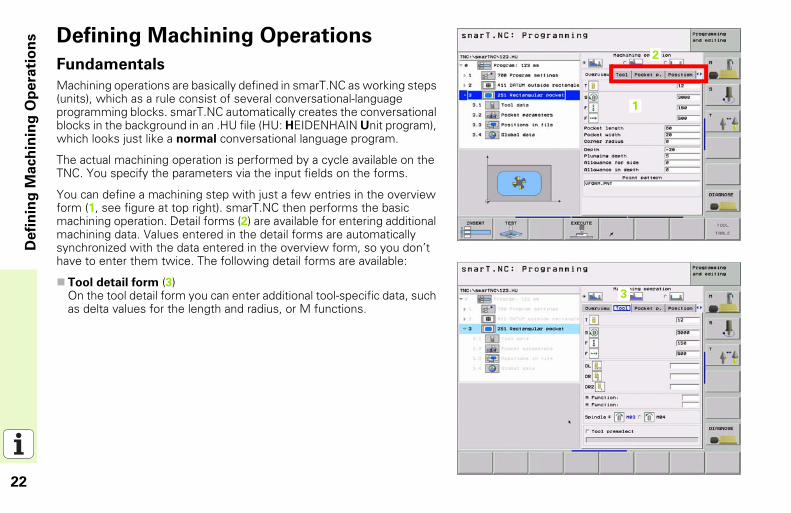
Machining operations are basically defined in smarT.NC as working steps (units), which as a rule consist of several conversational-language programming blocks. smarT.NC automatically creates the conversational blocks in the background in an .HU file (HU: HEIDENHAIN Unit program), which looks just like a normal conversational language program.
The actual machining operation is performed by a cycle available on the TNC. You specify the parameters via the input fields on the forms.
You can define a machining step with just a few entries in the overview form (1, see figure at top right). smarT.NC then performs the basic machining operation. Detail forms (2) are available for entering additional machining data. Values entered in the detail forms are automatically synchronized with the data entered in the overview form, so you don’t have to enter them twice. The following detail forms are available:
Tool detail form (3)On the tool detail form you can enter additional tool-specific data, such as delta values for the length and radius, or M functions.
11
12
13
23
Defi
nin
g M
ach
inin
g O
pera
tio
ns
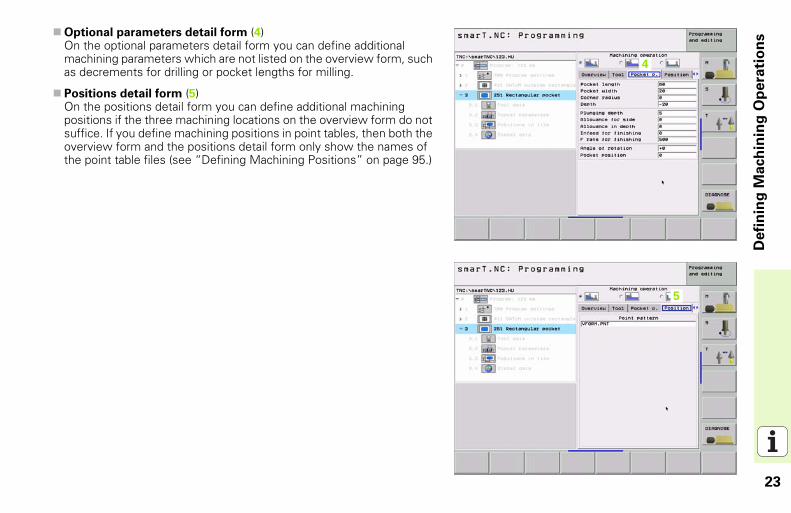
Optional parameters detail form (4)On the optional parameters detail form you can define additional machining parameters which are not listed on the overview form, such as decrements for drilling or pocket lengths for milling.
Positions detail form (5)On the positions detail form you can define additional machining positions if the three machining locations on the overview form do not suffice. If you define machining positions in point tables, then both the overview form and the positions detail form only show the names of the point table files (see “Defining Machining Positions” on page 95.)
15
14
24
Defi
nin
g M
ach
inin
g O
pera
tio
ns
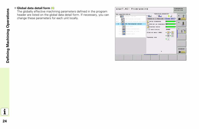
Global data detail form (6)The globally effective machining parameters defined in the program header are listed on the global data detail form. If necessary, you can change these parameters for each unit locally.
16
25
Defi
nin
g M
ach
inin
g O
pera
tio
ns
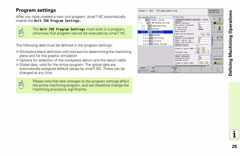
Program settingsAfter you have created a new unit program, smarT.NC automatically inserts the Unit 700 Program Settings.
The following data must be defined in the program settings:
Workpiece blank definition with tool axis for determining the machining plane and for the graphic simulationOptions for selection of the workpiece datum and the datum tableGlobal data, valid for the entire program. The global data are automatically assigned default values by smarT.NC. These can be changed at any time.
The Unit 700 Program Settings must exist in a program, otherwise that program cannot be executed by smarT.NC.
Please note that later changes to the program settings affect the entire machining program, and can therefore change the machining procedure significantly.
26
Defi
nin
g M
ach
inin
g O
pera
tio
ns
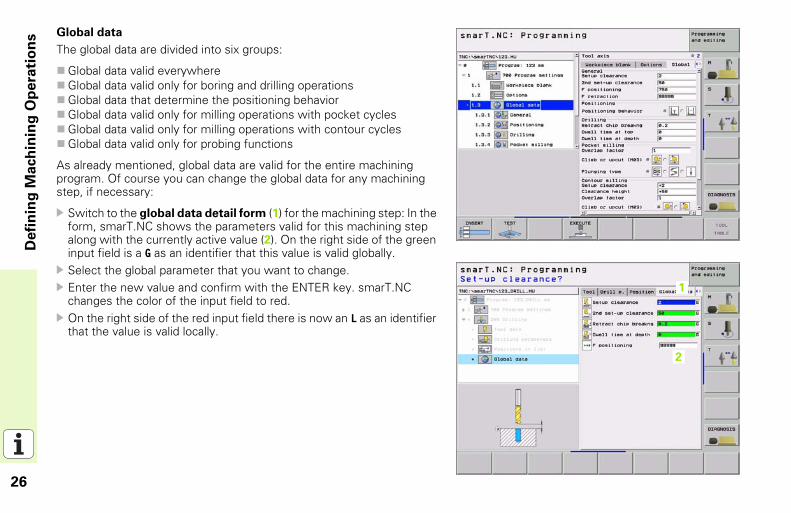
Global dataThe global data are divided into six groups:
Global data valid everywhereGlobal data valid only for boring and drilling operationsGlobal data that determine the positioning behaviorGlobal data valid only for milling operations with pocket cyclesGlobal data valid only for milling operations with contour cyclesGlobal data valid only for probing functions
As already mentioned, global data are valid for the entire machining program. Of course you can change the global data for any machining step, if necessary:
Switch to the global data detail form (1) for the machining step: In the form, smarT.NC shows the parameters valid for this machining step along with the currently active value (2). On the right side of the green input field is a G as an identifier that this value is valid globally.Select the global parameter that you want to change.Enter the new value and confirm with the ENTER key. smarT.NC changes the color of the input field to red.On the right side of the red input field there is now an L as an identifier that the value is valid locally.
11
12
27
Defi
nin
g M
ach
inin
g O
pera
tio
ns
Changing a global parameter on the global data detail form only effects a local change of the parameter, valid for that one machining step. smarT.NC displays the input fields of locally changed parameters with a red background. On the right side of the input field is an L which identifies the value as valid locally.
Press the SET STANDARD VALUES soft key to load and therefore activate the value of the global parameter from the program header. The input field of a global parameter whose value from the program header is in effect is displayed with a green background by smarT.NC. On the right side of the input field is a G which identifies the value as valid globally.
28
Defi
nin
g M
ach
inin
g O
pera
tio
ns
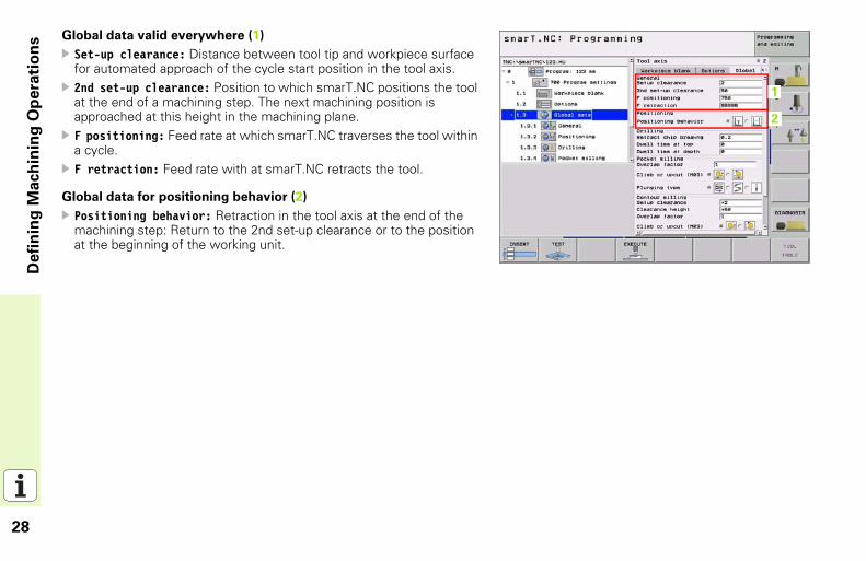
Global data valid everywhere (1)Set-up clearance: Distance between tool tip and workpiece surface for automated approach of the cycle start position in the tool axis.2nd set-up clearance: Position to which smarT.NC positions the tool at the end of a machining step. The next machining position is approached at this height in the machining plane.F positioning: Feed rate at which smarT.NC traverses the tool within a cycle.F retraction: Feed rate with at smarT.NC retracts the tool.
Global data for positioning behavior (2)
Positioning behavior: Retraction in the tool axis at the end of the machining step: Return to the 2nd set-up clearance or to the position at the beginning of the working unit.
11
12
29
Defi
nin
g M
ach
inin
g O
pera
tio
ns
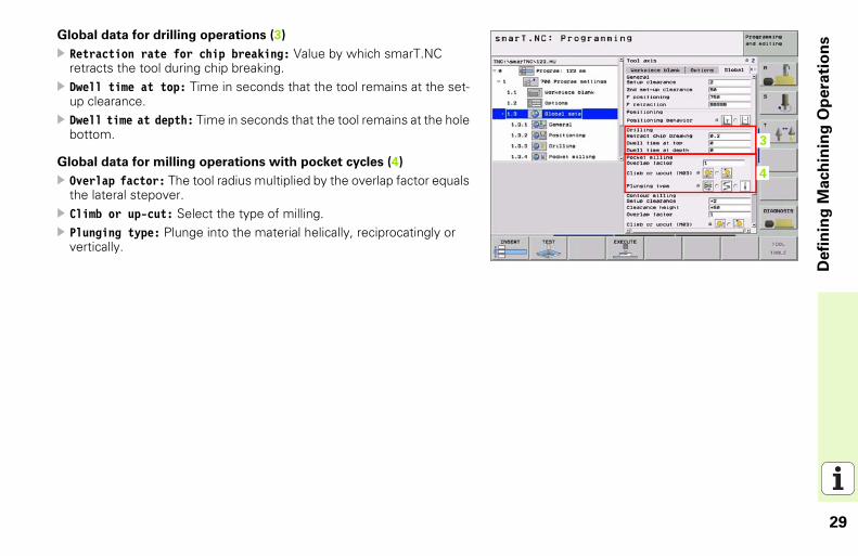
Global data for drilling operations (3)Retraction rate for chip breaking: Value by which smarT.NC retracts the tool during chip breaking.Dwell time at top: Time in seconds that the tool remains at the set-up clearance.Dwell time at depth: Time in seconds that the tool remains at the hole bottom.
Global data for milling operations with pocket cycles (4)
Overlap factor: The tool radius multiplied by the overlap factor equals the lateral stepover.Climb or up-cut: Select the type of milling.Plunging type: Plunge into the material helically, reciprocatingly or vertically.
13
14
30
Defi
nin
g M
ach
inin
g O
pera
tio
ns
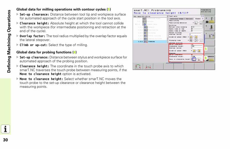
Global data for milling operations with contour cycles (5)Set-up clearance: Distance between tool tip and workpiece surface for automated approach of the cycle start position in the tool axis.Clearance height: Absolute height at which the tool cannot collide with the workpiece (for intermediate positioning and retraction at the end of the cycle).Overlap factor: The tool radius multiplied by the overlap factor equals the lateral stepover.Climb or up-cut: Select the type of milling.
Global data for probing functions (6)
Set-up clearance: Distance between stylus and workpiece surface for automated approach of the probing position.Clearance height: The coordinate in the touch probe axis to which smarT.NC traverses the touch probe between measuring points, if the Move to clearance height option is activated.Move to clearance height: Select whether smarT.NC moves the touch probe to the set-up clearance or clearance height between the measuring points.
15
16
31
Defi
nin
g M
ach
inin
g O
pera
tio
ns
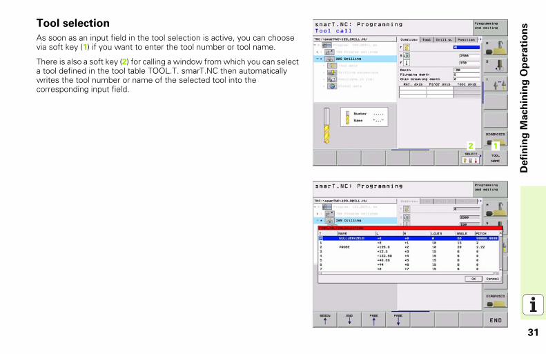
Tool selectionAs soon as an input field in the tool selection is active, you can choose via soft key (1) if you want to enter the tool number or tool name.
There is also a soft key (2) for calling a window from which you can select a tool defined in the tool table TOOL.T. smarT.NC then automatically writes the tool number or name of the selected tool into the corresponding input field.
1112
32
Defi
nin
g M
ach
inin
g O
pera
tio
ns
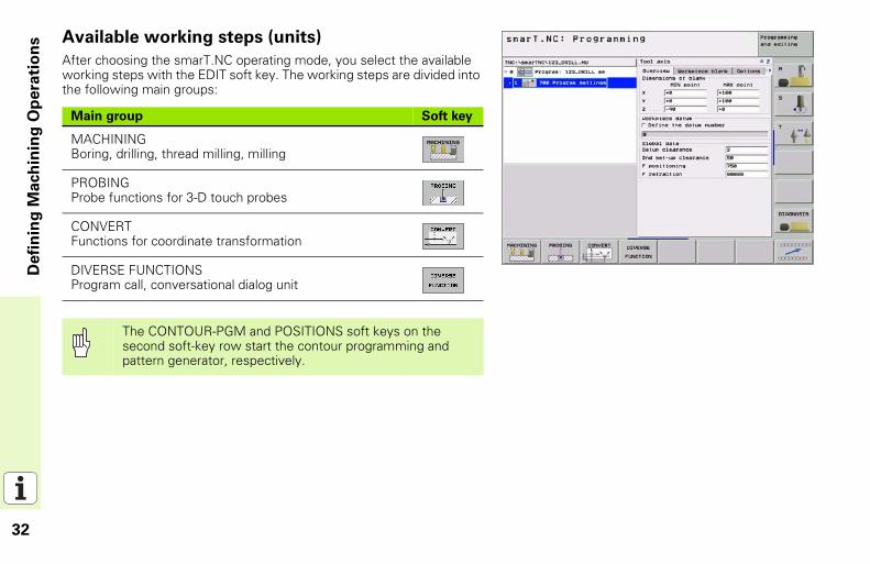
Available working steps (units)After choosing the smarT.NC operating mode, you select the available working steps with the EDIT soft key. The working steps are divided into the following main groups:
Main group Soft key
MACHININGBoring, drilling, thread milling, milling
PROBINGProbe functions for 3-D touch probes
CONVERTFunctions for coordinate transformation
DIVERSE FUNCTIONSProgram call, conversational dialog unit
The CONTOUR-PGM and POSITIONS soft keys on the second soft-key row start the contour programming and pattern generator, respectively.
33
Defi
nin
g M
ach
inin
g O
pera
tio
ns
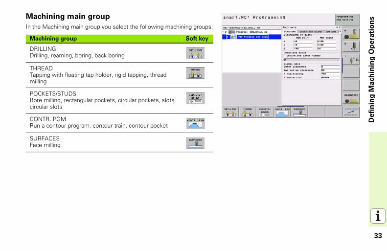
Machining main groupIn the Machining main group you select the following machining groups:
Machining group Soft key
DRILLINGDrilling, reaming, boring, back boring
THREADTapping with floating tap holder, rigid tapping, thread milling
POCKETS/STUDSBore milling, rectangular pockets, circular pockets, slots, circular slots
CONTR. PGMRun a contour program: contour train, contour pocket
SURFACESFace milling
34
Defi
nin
g M
ach
inin
g O
pera
tio
ns
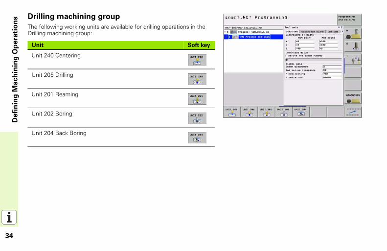
Drilling machining groupThe following working units are available for drilling operations in the Drilling machining group:
Unit Soft key
Unit 240 Centering
Unit 205 Drilling
Unit 201 Reaming
Unit 202 Boring
Unit 204 Back Boring
35
Defi
nin
g M
ach
inin
g O
pera
tio
ns
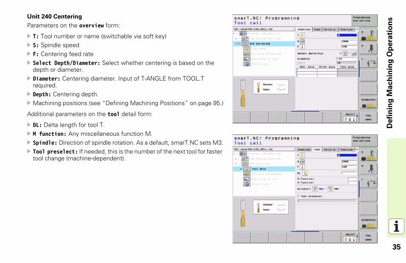
Unit 240 CenteringParameters on the overview form:
T: Tool number or name (switchable via soft key)S: Spindle speedF: Centering feed rateSelect Depth/Diameter: Select whether centering is based on the depth or diameter.Diameter: Centering diameter. Input of T-ANGLE from TOOL.T required.Depth: Centering depth.Machining positions (see “Defining Machining Positions” on page 95.)
Additional parameters on the tool detail form:
DL: Delta length for tool T.M function: Any miscellaneous function M.Spindle: Direction of spindle rotation. As a default, smarT.NC sets M3.Tool preselect: If needed, this is the number of the next tool for faster tool change (machine-dependent).
36
Defi
nin
g M
ach
inin
g O
pera
tio
ns
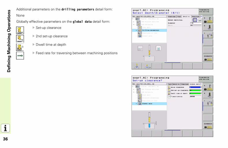
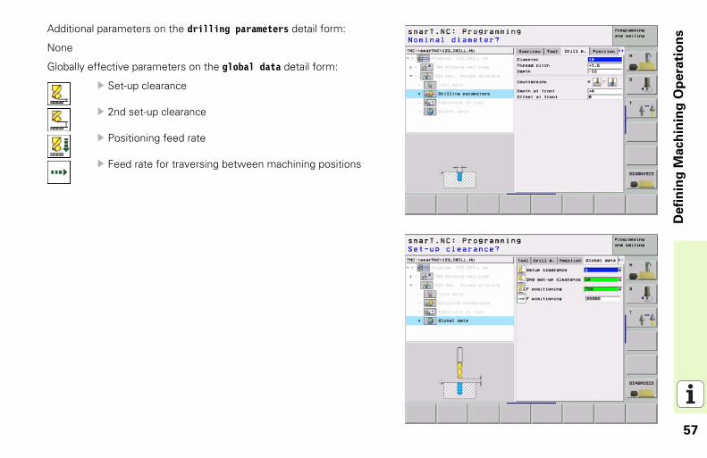
Additional parameters on the drilling parameters detail form:None
Globally effective parameters on the global data detail form:
Set-up clearance
2nd set-up clearance
Dwell time at depth
Feed rate for traversing between machining positions
37
Defi
nin
g M
ach
inin
g O
pera
tio
ns
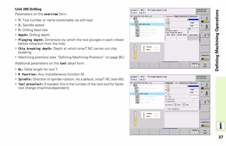
Unit 205 DrillingParameters on the overview form:
T: Tool number or name (switchable via soft key)S: Spindle speedF: Drilling feed rateDepth: Drilling depth.Plunging depth: Dimension by which the tool plunges in each infeed before retraction from the hole.Chip breaking depth: Depth at which smarT.NC carries out chip breaking.Machining positions (see “Defining Machining Positions” on page 95.)
Additional parameters on the tool detail form:
DL: Delta length for tool T.M function: Any miscellaneous function M.Spindle: Direction of spindle rotation. As a default, smarT.NC sets M3.Tool preselect: If needed, this is the number of the next tool for faster tool change (machine-dependent).
38
Defi
nin
g M
ach
inin
g O
pera
tio
ns
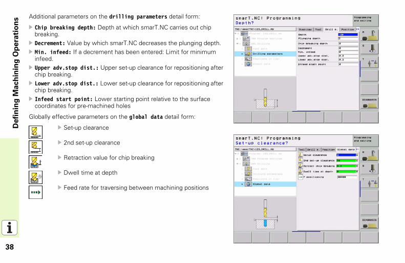
Additional parameters on the drilling parameters detail form:Chip breaking depth: Depth at which smarT.NC carries out chip breaking.Decrement: Value by which smarT.NC decreases the plunging depth.Min. infeed: If a decrement has been entered: Limit for minimum infeed.Upper adv.stop dist.: Upper set-up clearance for repositioning after chip breaking.Lower adv.stop dist.: Lower set-up clearance for repositioning after chip breaking.Infeed start point: Lower starting point relative to the surface coordinates for pre-machined holes
Globally effective parameters on the global data detail form:
Set-up clearance
2nd set-up clearance
Retraction value for chip breaking
Dwell time at depth
Feed rate for traversing between machining positions
39
Defi
nin
g M
ach
inin
g O
pera
tio
ns
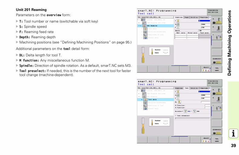
Unit 201 ReamingParameters on the overview form:
T: Tool number or name (switchable via soft key)S: Spindle speedF: Reaming feed rateDepth: Reaming depthMachining positions (see “Defining Machining Positions” on page 95.)
Additional parameters on the tool detail form:
DL: Delta length for tool T.M function: Any miscellaneous function M.Spindle: Direction of spindle rotation. As a default, smarT.NC sets M3.Tool preselect: If needed, this is the number of the next tool for faster tool change (machine-dependent).

40
Defi
nin
g M
ach
inin
g O
pera
tio
ns
Additional parameters on the drilling parameters detail form:None
Globally effective parameters on the global data detail form:
Set-up clearance
2nd set-up clearance
Retraction feed rate
Dwell time at depth
Feed rate for traversing between machining positions
41
Defi
nin
g M
ach
inin
g O
pera
tio
ns
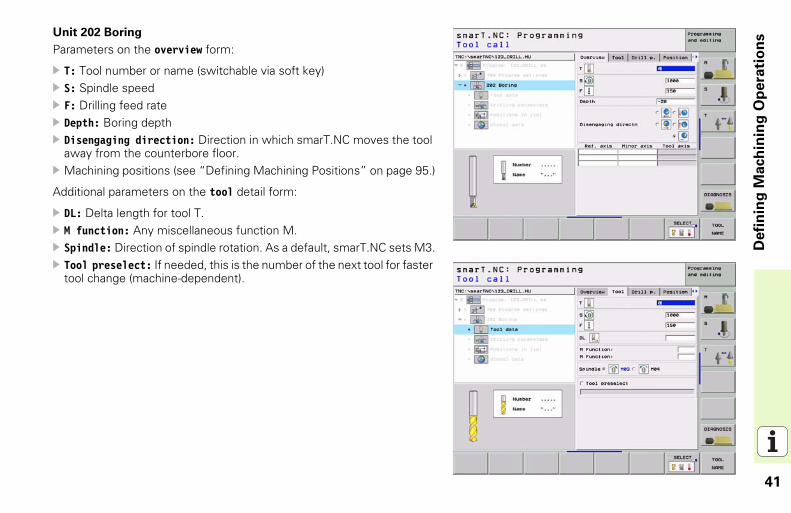
Unit 202 BoringParameters on the overview form:
T: Tool number or name (switchable via soft key)S: Spindle speedF: Drilling feed rateDepth: Boring depthDisengaging direction: Direction in which smarT.NC moves the tool away from the counterbore floor.Machining positions (see “Defining Machining Positions” on page 95.)
Additional parameters on the tool detail form:
DL: Delta length for tool T.M function: Any miscellaneous function M.Spindle: Direction of spindle rotation. As a default, smarT.NC sets M3.Tool preselect: If needed, this is the number of the next tool for faster tool change (machine-dependent).
42
Defi
nin
g M
ach
inin
g O
pera
tio
ns
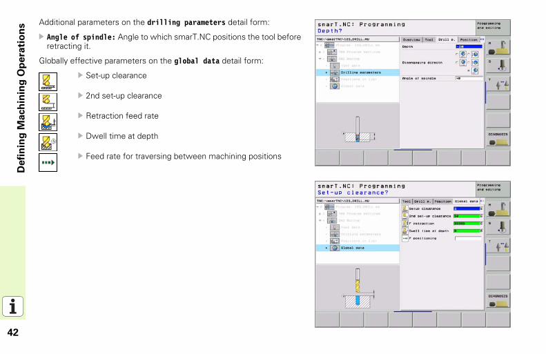
Additional parameters on the drilling parameters detail form:Angle of spindle: Angle to which smarT.NC positions the tool before retracting it.
Globally effective parameters on the global data detail form:
Set-up clearance
2nd set-up clearance
Retraction feed rate
Dwell time at depth
Feed rate for traversing between machining positions
43
Defi
nin
g M
ach
inin
g O
pera
tio
ns
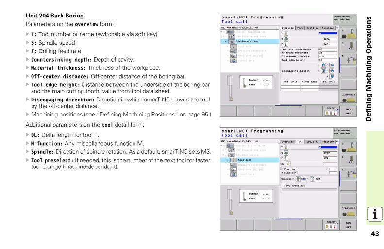
Unit 204 Back BoringParameters on the overview form:
T: Tool number or name (switchable via soft key)S: Spindle speedF: Drilling feed rateCountersinking depth: Depth of cavity.Material thickness: Thickness of the workpiece.Off-center distance: Off-center distance of the boring bar.Tool edge height: Distance between the underside of the boring bar and the main cutting tooth; value from tool data sheet.Disengaging direction: Direction in which smarT.NC moves the tool by the off-center distance.Machining positions (see “Defining Machining Positions” on page 95.)
Additional parameters on the tool detail form:
DL: Delta length for tool T.M function: Any miscellaneous function M.Spindle: Direction of spindle rotation. As a default, smarT.NC sets M3.Tool preselect: If needed, this is the number of the next tool for faster tool change (machine-dependent).
44
Defi
nin
g M
ach
inin
g O
pera
tio
ns
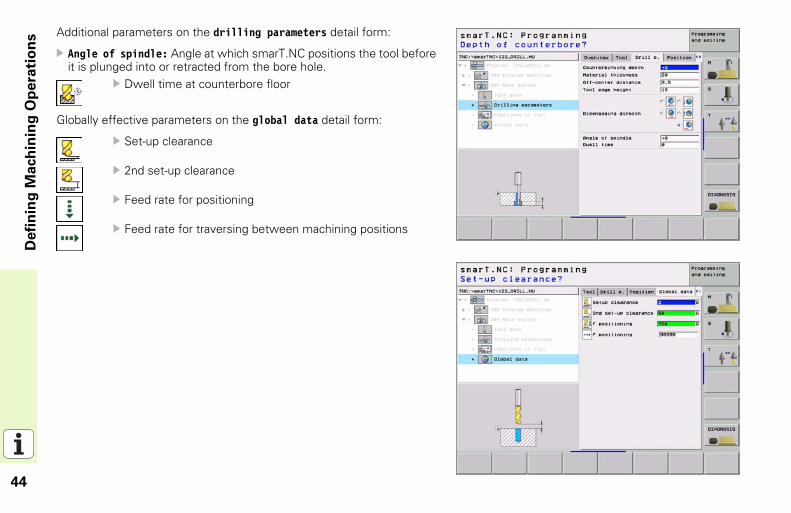
Additional parameters on the drilling parameters detail form:Angle of spindle: Angle at which smarT.NC positions the tool before it is plunged into or retracted from the bore hole.
Dwell time at counterbore floor
Globally effective parameters on the global data detail form:
Set-up clearance
2nd set-up clearance
Feed rate for positioning
Feed rate for traversing between machining positions
45
Defi
nin
g M
ach
inin
g O
pera
tio
ns
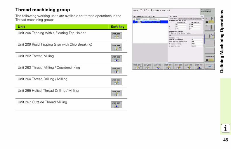
Thread machining groupThe following working units are available for thread operations in the Thread machining group:
Unit Soft key
Unit 206 Tapping with a Floating Tap Holder
Unit 209 Rigid Tapping (also with Chip Breaking)
Unit 262 Thread Milling
Unit 263 Thread Milling / Countersinking
Unit 264 Thread Drilling / Milling
Unit 265 Helical Thread Drilling / Milling
Unit 267 Outside Thread Milling
46
Defi
nin
g M
ach
inin
g O
pera
tio
ns
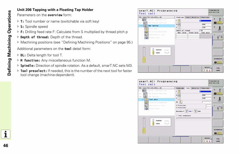
Unit 206 Tapping with a Floating Tap HolderParameters on the overview form:
T: Tool number or name (switchable via soft key)S: Spindle speedF: Drilling feed rate F: Calculate from S multiplied by thread pitch pDepth of thread: Depth of the thread.Machining positions (see “Defining Machining Positions” on page 95.)
Additional parameters on the tool detail form:
DL: Delta length for tool T.M function: Any miscellaneous function M.Spindle: Direction of spindle rotation. As a default, smarT.NC sets M3.Tool preselect: If needed, this is the number of the next tool for faster tool change (machine-dependent).
47
Defi
nin
g M
ach
inin
g O
pera
tio
ns
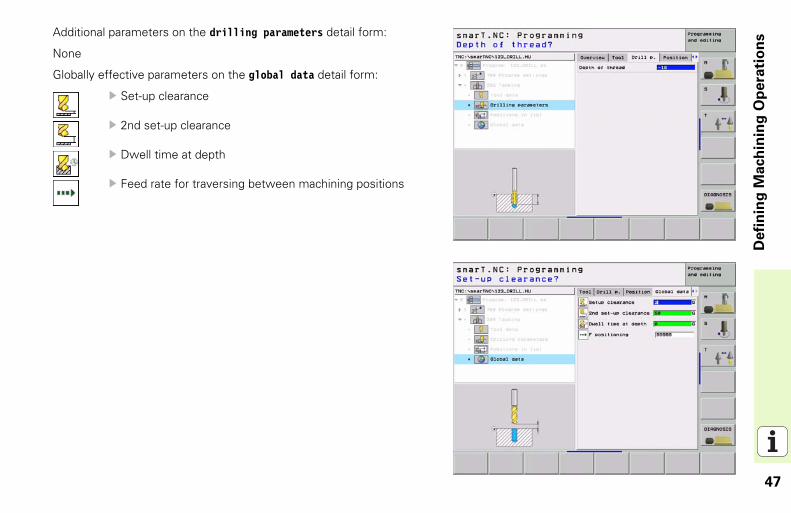
Additional parameters on the drilling parameters detail form:None
Globally effective parameters on the global data detail form:
Set-up clearance
2nd set-up clearance
Dwell time at depth
Feed rate for traversing between machining positions
48
Defi
nin
g M
ach
inin
g O
pera
tio
ns
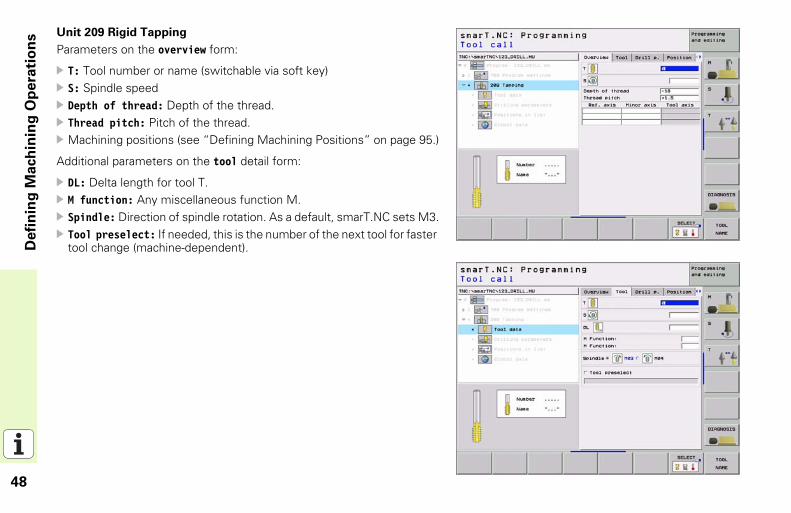
Unit 209 Rigid TappingParameters on the overview form:
T: Tool number or name (switchable via soft key)S: Spindle speedDepth of thread: Depth of the thread.Thread pitch: Pitch of the thread.Machining positions (see “Defining Machining Positions” on page 95.)
Additional parameters on the tool detail form:
DL: Delta length for tool T.M function: Any miscellaneous function M.Spindle: Direction of spindle rotation. As a default, smarT.NC sets M3.Tool preselect: If needed, this is the number of the next tool for faster tool change (machine-dependent).
49
Defi
nin
g M
ach
inin
g O
pera
tio
ns
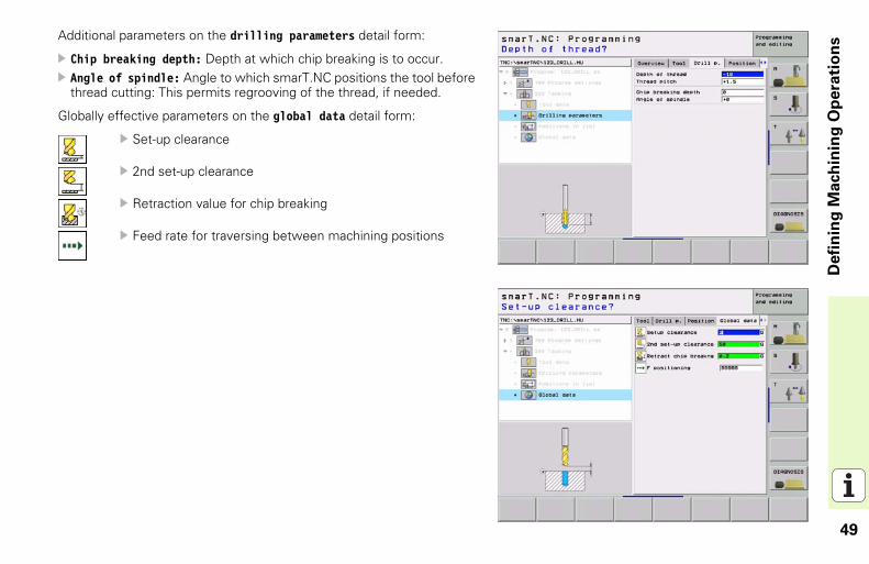
Additional parameters on the drilling parameters detail form:Chip breaking depth: Depth at which chip breaking is to occur.Angle of spindle: Angle to which smarT.NC positions the tool before thread cutting: This permits regrooving of the thread, if needed.
Globally effective parameters on the global data detail form:
Set-up clearance
2nd set-up clearance
Retraction value for chip breaking
Feed rate for traversing between machining positions
50
Defi
nin
g M
ach
inin
g O
pera
tio
ns
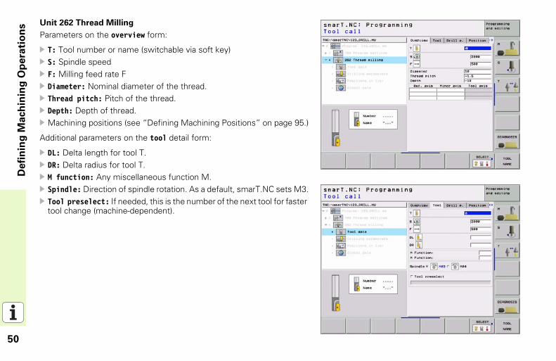
Unit 262 Thread MillingParameters on the overview form:
T: Tool number or name (switchable via soft key)S: Spindle speedF: Milling feed rate FDiameter: Nominal diameter of the thread.Thread pitch: Pitch of the thread.Depth: Depth of thread.Machining positions (see “Defining Machining Positions” on page 95.)
Additional parameters on the tool detail form:
DL: Delta length for tool T.DR: Delta radius for tool T.M function: Any miscellaneous function M.Spindle: Direction of spindle rotation. As a default, smarT.NC sets M3.Tool preselect: If needed, this is the number of the next tool for faster tool change (machine-dependent).
51
Defi
nin
g M
ach
inin
g O
pera
tio
ns
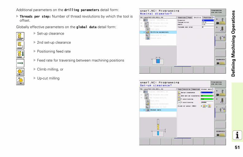
Additional parameters on the drilling parameters detail form:Threads per step: Number of thread revolutions by which the tool is offset.
Globally effective parameters on the global data detail form:
Set-up clearance
2nd set-up clearance
Positioning feed rate
Feed rate for traversing between machining positions
Climb milling, or
Up-cut milling
52
Defi
nin
g M
ach
inin
g O
pera
tio
ns
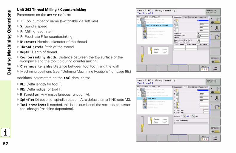
Unit 263 Thread Milling / CountersinkingParameters on the overview form:
T: Tool number or name (switchable via soft key)S: Spindle speedF: Milling feed rate FF: Feed rate F for countersinkingDiameter: Nominal diameter of the threadThread pitch: Pitch of the thread.Depth: Depth of thread.Countersinking depth: Distance between the top surface of the workpiece and the tool tip during countersinking.Clearance to side: Distance between tool tooth and the wall.Machining positions (see “Defining Machining Positions” on page 95.)
Additional parameters on the tool detail form:
DL: Delta length for tool T.DR: Delta radius for tool T.M function: Any miscellaneous function M.Spindle: Direction of spindle rotation. As a default, smarT.NC sets M3.Tool preselect: If needed, this is the number of the next tool for faster tool change (machine-dependent).
53
Defi
nin
g M
ach
inin
g O
pera
tio
ns
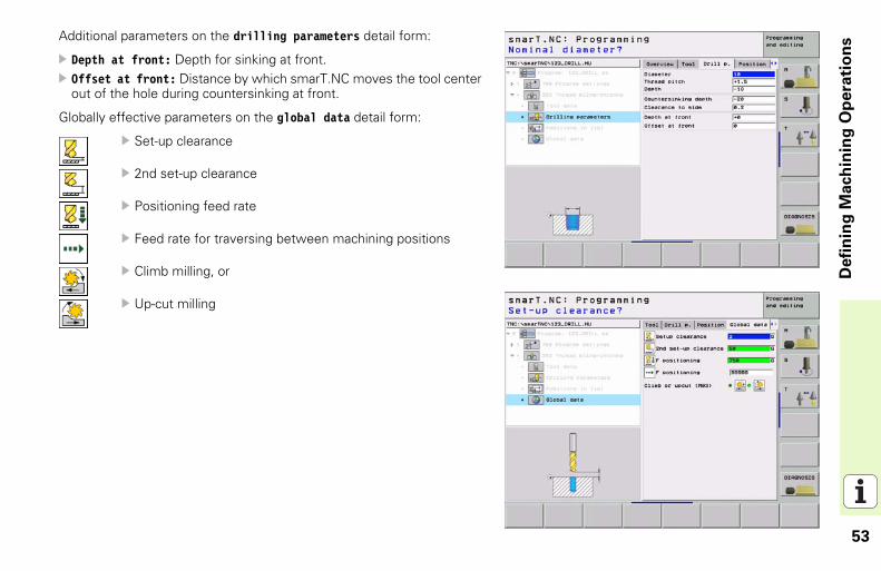
Additional parameters on the drilling parameters detail form:Depth at front: Depth for sinking at front.Offset at front: Distance by which smarT.NC moves the tool center out of the hole during countersinking at front.
Globally effective parameters on the global data detail form:
Set-up clearance
2nd set-up clearance
Positioning feed rate
Feed rate for traversing between machining positions
Climb milling, or
Up-cut milling
54
Defi
nin
g M
ach
inin
g O
pera
tio
ns
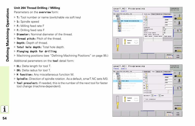
Unit 264 Thread Drilling / MillingParameters on the overview form:
T: Tool number or name (switchable via soft key)S: Spindle speedF: Milling feed rate FF: Drilling feed rate FDiameter: Nominal diameter of the thread.Thread pitch: Pitch of the thread.Depth: Depth of thread.Total hole depth: Total hole depth.Plunging depth for drillingMachining positions (see “Defining Machining Positions” on page 95.)
Additional parameters on the tool detail form:
DL: Delta length for tool T.DR: Delta radius for tool T.M function: Any miscellaneous function M.Spindle: Direction of spindle rotation. As a default, smarT.NC sets M3.Tool preselect: If needed, this is the number of the next tool for faster tool change (machine-dependent).
55
Defi
nin
g M
ach
inin
g O
pera
tio
ns
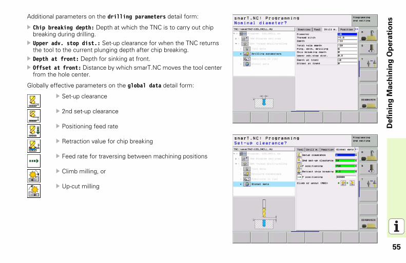
Additional parameters on the drilling parameters detail form:Chip breaking depth: Depth at which the TNC is to carry out chip breaking during drilling.Upper adv. stop dist.: Set-up clearance for when the TNC returns the tool to the current plunging depth after chip breaking.Depth at front: Depth for sinking at front.Offset at front: Distance by which smarT.NC moves the tool center from the hole center.
Globally effective parameters on the global data detail form:
Set-up clearance
2nd set-up clearance
Positioning feed rate
Retraction value for chip breaking
Feed rate for traversing between machining positions
Climb milling, or
Up-cut milling
56
Defi
nin
g M
ach
inin
g O
pera
tio
ns
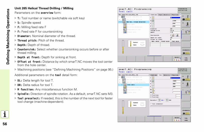
Unit 265 Helical Thread Drilling / MillingParameters on the overview form:
T: Tool number or name (switchable via soft key)S: Spindle speedF: Milling feed rate FF: Feed rate F for countersinkingDiameter: Nominal diameter of the thread.Thread pitch: Pitch of the thread.Depth: Depth of thread.Countersink: Select whether countersinking occurs before or after thread milling.Depth at front: Depth for sinking at front.Offset at front: Distance by which smarT.NC moves the tool center from the hole center.Machining positions (see “Defining Machining Positions” on page 95.)
Additional parameters on the tool detail form:
DL: Delta length for tool T.DR: Delta radius for tool T.M function: Any miscellaneous function M.Spindle: Direction of spindle rotation. As a default, smarT.NC sets M3.Tool preselect: If needed, this is the number of the next tool for faster tool change (machine-dependent).
57
Defi
nin
g M
ach
inin
g O
pera
tio
ns
Additional parameters on the drilling parameters detail form:None
Globally effective parameters on the global data detail form:
Set-up clearance
2nd set-up clearance
Positioning feed rate
Feed rate for traversing between machining positions
58
Defi
nin
g M
ach
inin
g O
pera
tio
ns
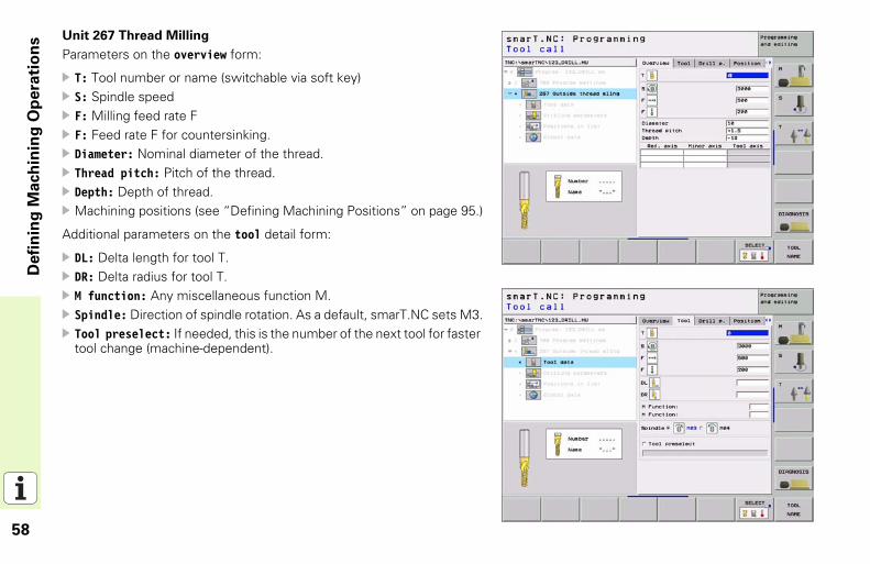
Unit 267 Thread MillingParameters on the overview form:
T: Tool number or name (switchable via soft key)S: Spindle speedF: Milling feed rate FF: Feed rate F for countersinking.Diameter: Nominal diameter of the thread.Thread pitch: Pitch of the thread.Depth: Depth of thread.Machining positions (see “Defining Machining Positions” on page 95.)
Additional parameters on the tool detail form:
DL: Delta length for tool T.DR: Delta radius for tool T.M function: Any miscellaneous function M.Spindle: Direction of spindle rotation. As a default, smarT.NC sets M3.Tool preselect: If needed, this is the number of the next tool for faster tool change (machine-dependent).
59
Defi
nin
g M
ach
inin
g O
pera
tio
ns
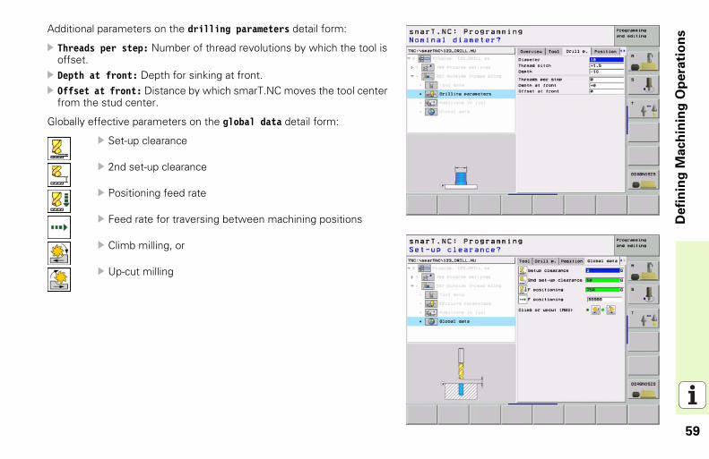
Additional parameters on the drilling parameters detail form:Threads per step: Number of thread revolutions by which the tool is offset.Depth at front: Depth for sinking at front.Offset at front: Distance by which smarT.NC moves the tool center from the stud center.
Globally effective parameters on the global data detail form:
Set-up clearance
2nd set-up clearance
Positioning feed rate
Feed rate for traversing between machining positions
Climb milling, or
Up-cut milling
60
Defi
nin
g M
ach
inin
g O
pera
tio
ns
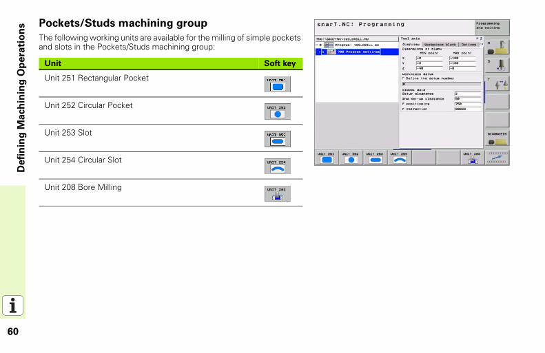
Pockets/Studs machining groupThe following working units are available for the milling of simple pockets and slots in the Pockets/Studs machining group:
Unit Soft key
Unit 251 Rectangular Pocket
Unit 252 Circular Pocket
Unit 253 Slot
Unit 254 Circular Slot
Unit 208 Bore Milling
61
Defi
nin
g M
ach
inin
g O
pera
tio
ns
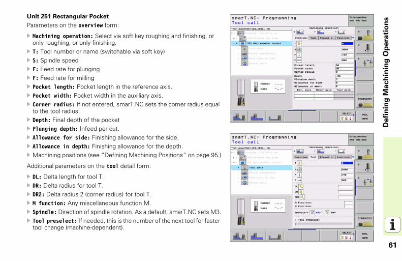
Unit 251 Rectangular PocketParameters on the overview form:
Machining operation: Select via soft key roughing and finishing, or only roughing, or only finishing.T: Tool number or name (switchable via soft key)S: Spindle speedF: Feed rate for plungingF: Feed rate for millingPocket length: Pocket length in the reference axis.Pocket width: Pocket width in the auxiliary axis.Corner radius: If not entered, smarT.NC sets the corner radius equal to the tool radius.Depth: Final depth of the pocketPlunging depth: Infeed per cut.Allowance for side: Finishing allowance for the side.Allowance in depth: Finishing allowance for the depth.Machining positions (see “Defining Machining Positions” on page 95.)
Additional parameters on the tool detail form:
DL: Delta length for tool T.DR: Delta radius for tool T.DR2: Delta radius 2 (corner radius) for tool T.M function: Any miscellaneous function M.Spindle: Direction of spindle rotation. As a default, smarT.NC sets M3.Tool preselect: If needed, this is the number of the next tool for faster tool change (machine-dependent).
62
Defi
nin
g M
ach
inin
g O
pera
tio
ns
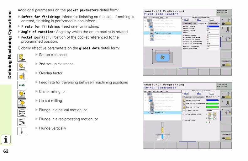
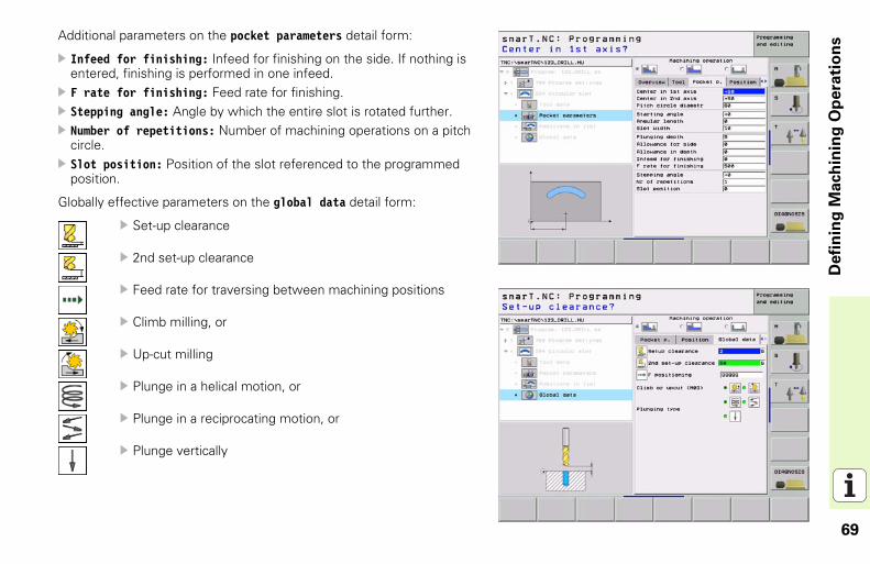
Additional parameters on the pocket parameters detail form:Infeed for finishing: Infeed for finishing on the side. If nothing is entered, finishing is performed in one infeed.F rate for finishing: Feed rate for finishing.Angle of rotation: Angle by which the entire pocket is rotated.Pocket position: Position of the pocket referenced to the programmed position.
Globally effective parameters on the global data detail form:
Set-up clearance
2nd set-up clearance
Overlap factor
Feed rate for traversing between machining positions
Climb milling, or
Up-cut milling
Plunge in a helical motion, or
Plunge in a reciprocating motion, or
Plunge vertically
63
Defi
nin
g M
ach
inin
g O
pera
tio
ns
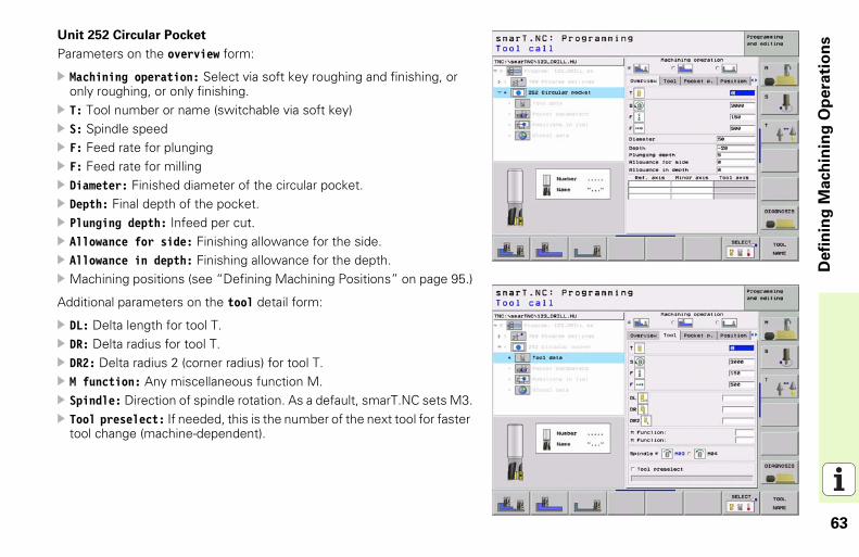
Unit 252 Circular PocketParameters on the overview form:
Machining operation: Select via soft key roughing and finishing, or only roughing, or only finishing.T: Tool number or name (switchable via soft key)S: Spindle speedF: Feed rate for plungingF: Feed rate for millingDiameter: Finished diameter of the circular pocket.Depth: Final depth of the pocket.Plunging depth: Infeed per cut.Allowance for side: Finishing allowance for the side.Allowance in depth: Finishing allowance for the depth.Machining positions (see “Defining Machining Positions” on page 95.)
Additional parameters on the tool detail form:
DL: Delta length for tool T.DR: Delta radius for tool T.DR2: Delta radius 2 (corner radius) for tool T.M function: Any miscellaneous function M.Spindle: Direction of spindle rotation. As a default, smarT.NC sets M3.Tool preselect: If needed, this is the number of the next tool for faster tool change (machine-dependent).
64
Defi
nin
g M
ach
inin
g O
pera
tio
ns
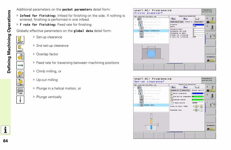
Additional parameters on the pocket parameters detail form:Infeed for finishing: Infeed for finishing on the side. If nothing is entered, finishing is performed in one infeed.F rate for finishing: Feed rate for finishing.
Globally effective parameters on the global data detail form:
Set-up clearance
2nd set-up clearance
Overlap factor
Feed rate for traversing between machining positions
Climb milling, or
Up-cut milling
Plunge in a helical motion, or
Plunge vertically
65
Defi
nin
g M
ach
inin
g O
pera
tio
ns
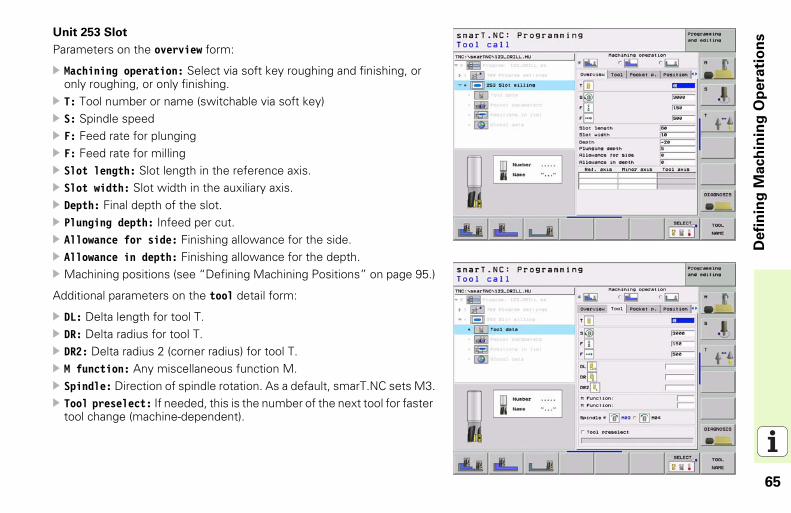
Unit 253 SlotParameters on the overview form:
Machining operation: Select via soft key roughing and finishing, or only roughing, or only finishing.T: Tool number or name (switchable via soft key)S: Spindle speedF: Feed rate for plungingF: Feed rate for millingSlot length: Slot length in the reference axis.Slot width: Slot width in the auxiliary axis.Depth: Final depth of the slot.Plunging depth: Infeed per cut.Allowance for side: Finishing allowance for the side.Allowance in depth: Finishing allowance for the depth.Machining positions (see “Defining Machining Positions” on page 95.)
Additional parameters on the tool detail form:
DL: Delta length for tool T.DR: Delta radius for tool T.DR2: Delta radius 2 (corner radius) for tool T.M function: Any miscellaneous function M.Spindle: Direction of spindle rotation. As a default, smarT.NC sets M3.Tool preselect: If needed, this is the number of the next tool for faster tool change (machine-dependent).
66
Defi
nin
g M
ach
inin
g O
pera
tio
ns
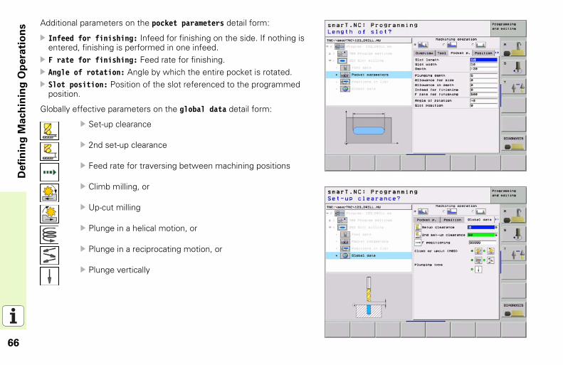
Additional parameters on the pocket parameters detail form:Infeed for finishing: Infeed for finishing on the side. If nothing is entered, finishing is performed in one infeed.F rate for finishing: Feed rate for finishing.Angle of rotation: Angle by which the entire pocket is rotated.Slot position: Position of the slot referenced to the programmed position.
Globally effective parameters on the global data detail form:
Set-up clearance
2nd set-up clearance
Feed rate for traversing between machining positions
Climb milling, or
Up-cut milling
Plunge in a helical motion, or
Plunge in a reciprocating motion, or
Plunge vertically
67
Defi
nin
g M
ach
inin
g O
pera
tio
ns
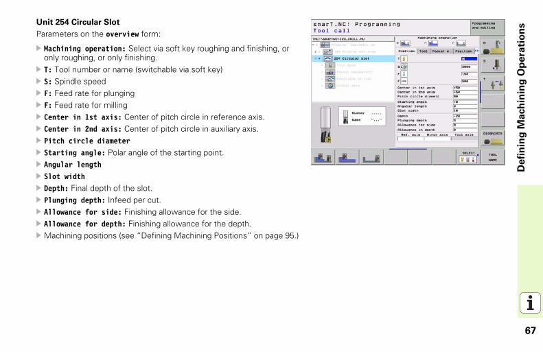
Unit 254 Circular SlotParameters on the overview form:
Machining operation: Select via soft key roughing and finishing, or only roughing, or only finishing.T: Tool number or name (switchable via soft key)S: Spindle speedF: Feed rate for plungingF: Feed rate for millingCenter in 1st axis: Center of pitch circle in reference axis.Center in 2nd axis: Center of pitch circle in auxiliary axis.Pitch circle diameterStarting angle: Polar angle of the starting point.Angular lengthSlot widthDepth: Final depth of the slot.Plunging depth: Infeed per cut.Allowance for side: Finishing allowance for the side.Allowance for depth: Finishing allowance for the depth.Machining positions (see “Defining Machining Positions” on page 95.)
68
Defi
nin
g M
ach
inin
g O
pera
tio
ns
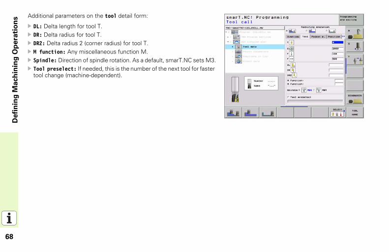
Additional parameters on the tool detail form:DL: Delta length for tool T.DR: Delta radius for tool T.DR2: Delta radius 2 (corner radius) for tool T.M function: Any miscellaneous function M.Spindle: Direction of spindle rotation. As a default, smarT.NC sets M3.Tool preselect: If needed, this is the number of the next tool for faster tool change (machine-dependent).
69
Defi
nin
g M
ach
inin
g O
pera
tio
ns
Additional parameters on the pocket parameters detail form:Infeed for finishing: Infeed for finishing on the side. If nothing is entered, finishing is performed in one infeed.F rate for finishing: Feed rate for finishing.Stepping angle: Angle by which the entire slot is rotated further.Number of repetitions: Number of machining operations on a pitch circle.Slot position: Position of the slot referenced to the programmed position.
Globally effective parameters on the global data detail form:
Set-up clearance
2nd set-up clearance
Feed rate for traversing between machining positions
Climb milling, or
Up-cut milling
Plunge in a helical motion, or
Plunge in a reciprocating motion, or
Plunge vertically
70
Defi
nin
g M
ach
inin
g O
pera
tio
ns
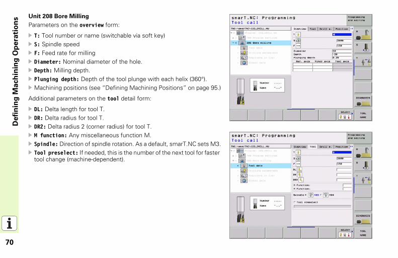
Unit 208 Bore MillingParameters on the overview form:
T: Tool number or name (switchable via soft key)S: Spindle speedF: Feed rate for millingDiameter: Nominal diameter of the hole.Depth: Milling depth.Plunging depth: Depth of the tool plunge with each helix (360°).Machining positions (see “Defining Machining Positions” on page 95.)
Additional parameters on the tool detail form:
DL: Delta length for tool T.DR: Delta radius for tool T.DR2: Delta radius 2 (corner radius) for tool T.M function: Any miscellaneous function M.Spindle: Direction of spindle rotation. As a default, smarT.NC sets M3.Tool preselect: If needed, this is the number of the next tool for faster tool change (machine-dependent).
71
Defi
nin
g M
ach
inin
g O
pera
tio
ns
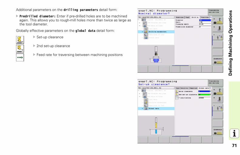
Additional parameters on the drilling parameters detail form:Predrilled diameter: Enter if pre-drilled holes are to be machined again. This allows you to rough-mill holes more than twice as large as the tool diameter.
Globally effective parameters on the global data detail form:
Set-up clearance
2nd set-up clearance
Feed rate for traversing between machining positions
72
Defi
nin
g M
ach
inin
g O
pera
tio
ns
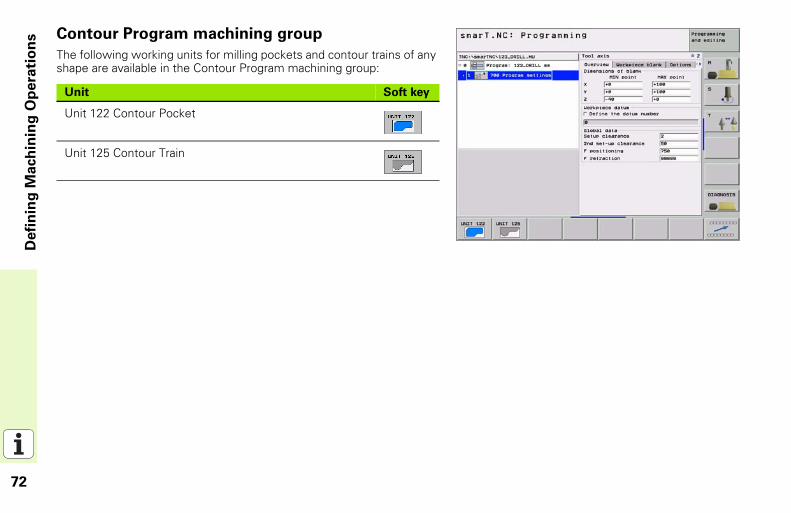
Contour Program machining groupThe following working units for milling pockets and contour trains of any shape are available in the Contour Program machining group:
Unit Soft key
Unit 122 Contour Pocket
Unit 125 Contour Train
73
Defi
nin
g M
ach
inin
g O
pera
tio
ns
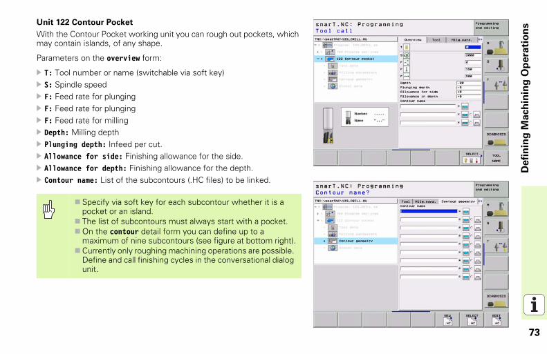
Unit 122 Contour PocketWith the Contour Pocket working unit you can rough out pockets, which may contain islands, of any shape.
Parameters on the overview form:
T: Tool number or name (switchable via soft key)S: Spindle speedF: Feed rate for plungingF: Feed rate for plungingF: Feed rate for millingDepth: Milling depthPlunging depth: Infeed per cut.Allowance for side: Finishing allowance for the side.Allowance for depth: Finishing allowance for the depth.Contour name: List of the subcontours (.HC files) to be linked.
Specify via soft key for each subcontour whether it is a pocket or an island.The list of subcontours must always start with a pocket.On the contour detail form you can define up to a maximum of nine subcontours (see figure at bottom right).Currently only roughing machining operations are possible. Define and call finishing cycles in the conversational dialog unit.
74
Defi
nin
g M
ach
inin
g O
pera
tio
ns
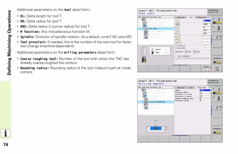
Additional parameters on the tool detail form:DL: Delta length for tool T.DR: Delta radius for tool T.DR2: Delta radius 2 (corner radius) for tool T.M function: Any miscellaneous function M.Spindle: Direction of spindle rotation. As a default, smarT.NC sets M3.Tool preselect: If needed, this is the number of the next tool for faster tool change (machine-dependent).
Additional parameters on the milling parameters detail form:
Coarse roughing tool: Number of the tool with which the TNC has already coarse-roughed the contour. Rounding radius: Rounding radius of the tool midpoint path at inside corners
75
Defi
nin
g M
ach
inin
g O
pera
tio
ns
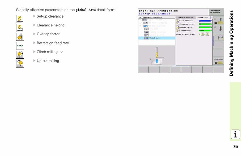
Globally effective parameters on the global data detail form:Set-up clearance
Clearance height
Overlap factor
Retraction feed rate
Climb milling, or
Up-cut milling

76
Defi
nin
g M
ach
inin
g O
pera
tio
ns
Unit 125 Contour TrainWith the Contour Train you can machine open and closed contours that you defined in an .HC program.
Parameters on the overview form:
T: Tool number or name (switchable via soft key)S: Spindle speedF: Feed rate for plungingF: Feed rate for millingContour name: Name of the contour file (.HC) to be machined.Radius compensation: Machine the contour with compensation to the left, to the right, or without compensation.Type of approach: Approach the contour tangentially on a circular path, or tangentially on a straight line, or vertically.Approach radius (Only in effect if tangential approach on a circular path was selected): Radius of the circular arc.Center angle (Only in effect if tangential approach on a circular path was selected): Angle of the circular arc.Distance to aux. point (Only in effect if tangential approach on a straight path or vertical approach was selected): Distance to the auxiliary point from which the contour is approached.Depth: Milling depth.Plunging depth: Infeed per cut.Allowance for side: Finishing allowance.Type of milling: Climb milling, up-cut milling or reciprocating machining.
77
Defi
nin
g M
ach
inin
g O
pera
tio
ns
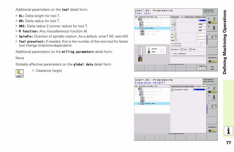
Additional parameters on the tool detail form:DL: Delta length for tool T.DR: Delta radius for tool T.DR2: Delta radius 2 (corner radius) for tool T.M function: Any miscellaneous function M.Spindle: Direction of spindle rotation. As a default, smarT.NC sets M3.Tool preselect: If needed, this is the number of the next tool for faster tool change (machine-dependent).
Additional parameters on the milling parameters detail form:
None
Globally effective parameters on the global data detail form:
Clearance height
78
Defi
nin
g M
ach
inin
g O
pera
tio
ns
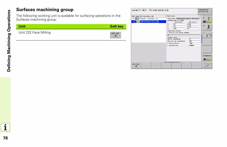
Surfaces machining groupThe following working unit is available for surfacing operations in the Surfaces machining group:
Unit Soft key
Unit 232 Face Milling
79
Defi
nin
g M
ach
inin
g O
pera
tio
ns
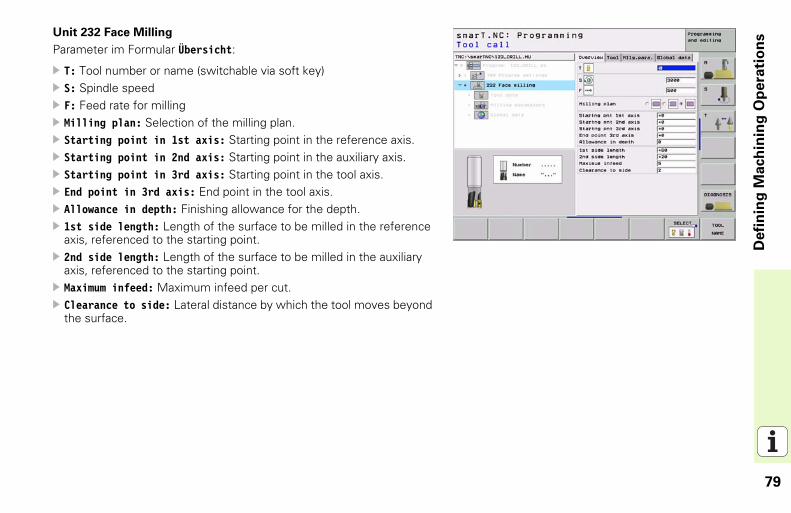
Unit 232 Face MillingParameter im Formular Übersicht:
T: Tool number or name (switchable via soft key)S: Spindle speedF: Feed rate for millingMilling plan: Selection of the milling plan.Starting point in 1st axis: Starting point in the reference axis.Starting point in 2nd axis: Starting point in the auxiliary axis.Starting point in 3rd axis: Starting point in the tool axis.End point in 3rd axis: End point in the tool axis.Allowance in depth: Finishing allowance for the depth.1st side length: Length of the surface to be milled in the reference axis, referenced to the starting point.2nd side length: Length of the surface to be milled in the auxiliary axis, referenced to the starting point.Maximum infeed: Maximum infeed per cut.Clearance to side: Lateral distance by which the tool moves beyond the surface.
80
Defi
nin
g M
ach
inin
g O
pera
tio
ns
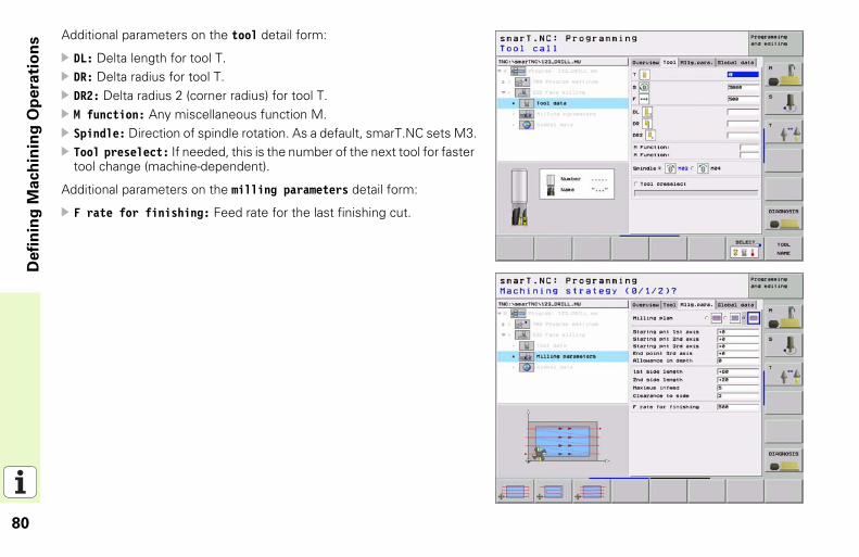
Additional parameters on the tool detail form:DL: Delta length for tool T.DR: Delta radius for tool T.DR2: Delta radius 2 (corner radius) for tool T.M function: Any miscellaneous function M.Spindle: Direction of spindle rotation. As a default, smarT.NC sets M3.Tool preselect: If needed, this is the number of the next tool for faster tool change (machine-dependent).
Additional parameters on the milling parameters detail form:
F rate for finishing: Feed rate for the last finishing cut.

81
Defi
nin
g M
ach
inin
g O
pera
tio
ns
Globally effective parameters on the global data detail form:Set-up clearance
2nd set-up clearance
Positioning feed rate
Overlap factor
82
Defi
nin
g M
ach
inin
g O
pera
tio
ns
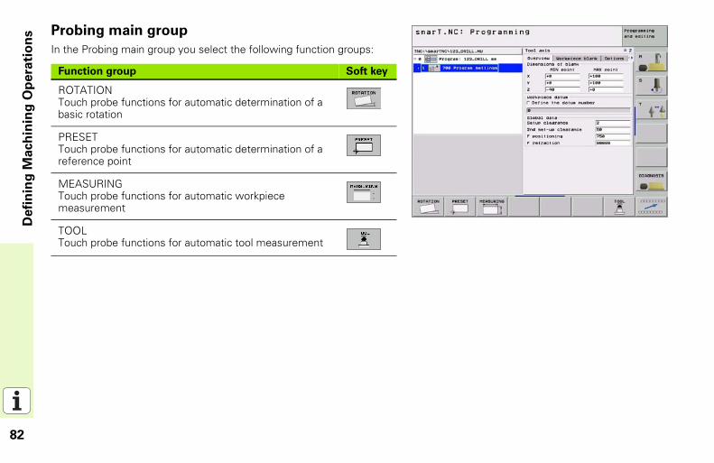
Probing main groupIn the Probing main group you select the following function groups:
Function group Soft key
ROTATIONTouch probe functions for automatic determination of a basic rotation
PRESETTouch probe functions for automatic determination of a reference point
MEASURINGTouch probe functions for automatic workpiece measurement
TOOLTouch probe functions for automatic tool measurement
83
Defi
nin
g M
ach
inin
g O
pera
tio
ns
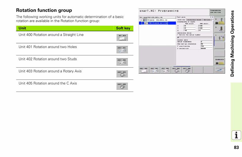
Rotation function groupThe following working units for automatic determination of a basic rotation are available in the Rotation function group:
Unit Soft key
Unit 400 Rotation around a Straight Line
Unit 401 Rotation around two Holes
Unit 402 Rotation around two Studs
Unit 403 Rotation around a Rotary Axis
Unit 405 Rotation around the C Axis
84
Defi
nin
g M
ach
inin
g O
pera
tio
ns
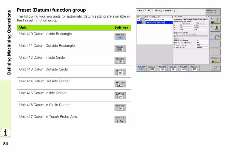
Preset (Datum) function groupThe following working units for automatic datum setting are available in the Preset function group:
Unit Soft key
Unit 410 Datum Inside Rectangle
Unit 411 Datum Outside Rectangle
Unit 412 Datum Inside Circle
Unit 413 Datum Outside Circle
Unit 414 Datum Outside Corner
Unit 415 Datum Inside Corner
Unit 416 Datum in Circle Center
Unit 417 Datum in Touch Probe Axis
85
Defi
nin
g M
ach
inin
g O
pera
tio
ns
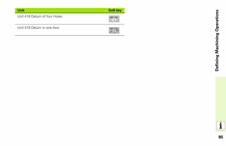
Unit 418 Datum of four Holes
Unit 419 Datum in one Axis
Unit Soft key
86
Defi
nin
g M
ach
inin
g O
pera
tio
ns
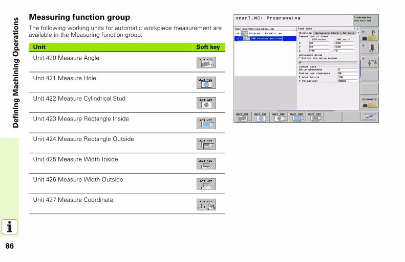
Measuring function groupThe following working units for automatic workpiece measurement are available in the Measuring function group:
Unit Soft key
Unit 420 Measure Angle
Unit 421 Measure Hole
Unit 422 Measure Cylindrical Stud
Unit 423 Measure Rectangle Inside
Unit 424 Measure Rectangle Outside
Unit 425 Measure Width Inside
Unit 426 Measure Width Outside
Unit 427 Measure Coordinate
87
Defi
nin
g M
ach
inin
g O
pera
tio
ns
Unit 430 Measure Bolt Hole Circle
Unit 431 Measure Plane
Unit Soft key
88
Defi
nin
g M
ach
inin
g O
pera
tio
ns
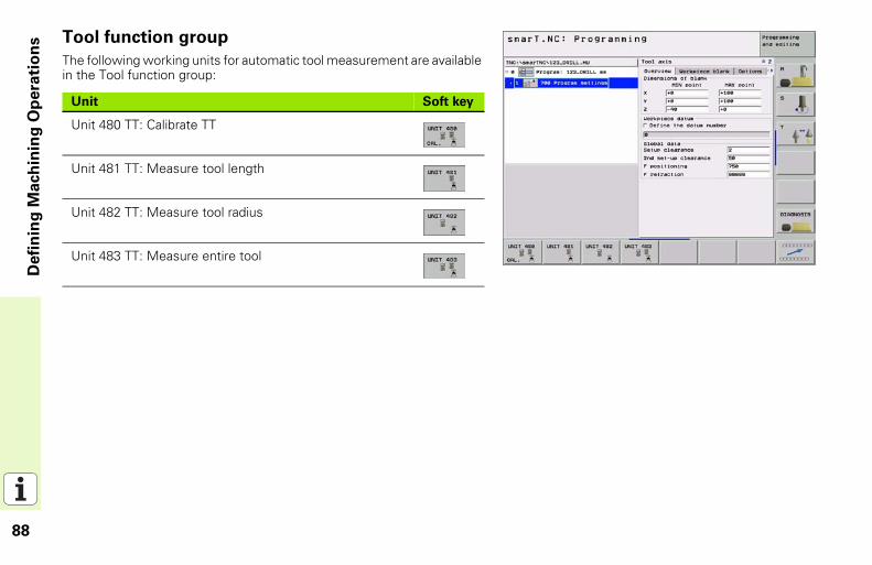
Tool function groupThe following working units for automatic tool measurement are available in the Tool function group:
Unit Soft key
Unit 480 TT: Calibrate TT
Unit 481 TT: Measure tool length
Unit 482 TT: Measure tool radius
Unit 483 TT: Measure entire tool
89
Defi
nin
g M
ach
inin
g O
pera
tio
ns
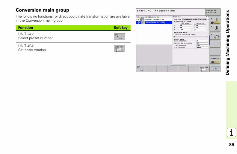
Conversion main groupThe following functions for direct coordinate transformation are available in the Conversion main group:
Function Soft key
UNIT 247:Select preset number
UNIT 404:Set basic rotation
90
Defi
nin
g M
ach
inin
g O
pera
tio
ns
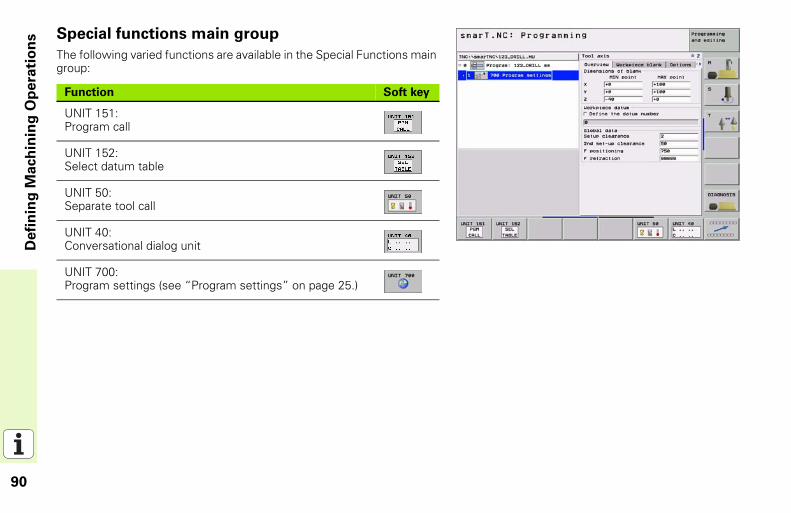
Special functions main groupThe following varied functions are available in the Special Functions main group:
Function Soft key
UNIT 151:Program call
UNIT 152:Select datum table
UNIT 50:Separate tool call
UNIT 40:Conversational dialog unit
UNIT 700:Program settings (see “Program settings” on page 25.)
91
Defi
nin
g M
ach
inin
g O
pera
tio
ns
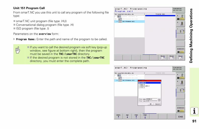
Unit 151 Program CallFrom smarT.NC you use this unit to call any program of the following file type:
smarT.NC unit program (file type .HU)Conversational dialog program (file type .H)ISO program (file type .I)
Parameters on the overview form:
Program Name: Enter the path and name of the program to be called.
If you want to call the desired program via soft key (pop-up window, see figure at bottom right), then the program must be saved in the TNC:\smarTNC directory.If the desired program is not stored in the TNC:\smarTNC directory, you must enter the complete path.
92
Defi
nin
g M
ach
inin
g O
pera
tio
ns
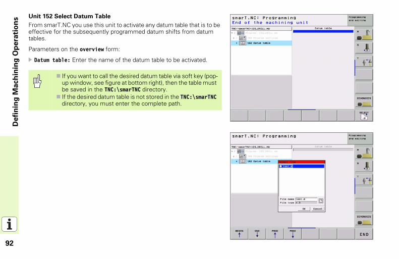
Unit 152 Select Datum TableFrom smarT.NC you use this unit to activate any datum table that is to be effective for the subsequently programmed datum shifts from datum tables.
Parameters on the overview form:
Datum table: Enter the name of the datum table to be activated.
If you want to call the desired datum table via soft key (pop-up window, see figure at bottom right), then the table must be saved in the TNC:\smarTNC directory.If the desired datum table is not stored in the TNC:\smarTNC directory, you must enter the complete path.
93
Defi
nin
g M
ach
inin
g O
pera
tio
ns
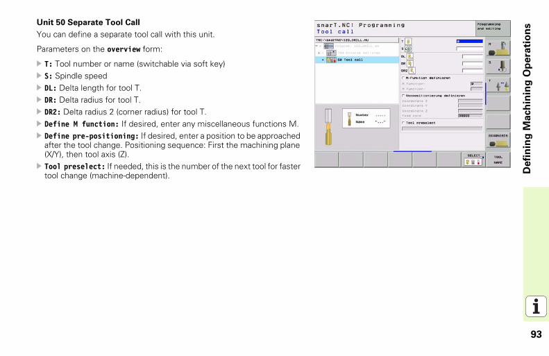
Unit 50 Separate Tool CallYou can define a separate tool call with this unit.
Parameters on the overview form:
T: Tool number or name (switchable via soft key)S: Spindle speedDL: Delta length for tool T.DR: Delta radius for tool T.DR2: Delta radius 2 (corner radius) for tool T.Define M function: If desired, enter any miscellaneous functions M.Define pre-positioning: If desired, enter a position to be approached after the tool change. Positioning sequence: First the machining plane (X/Y), then tool axis (Z).Tool preselect: If needed, this is the number of the next tool for faster tool change (machine-dependent).
94
Defi
nin
g M
ach
inin
g O
pera
tio
ns
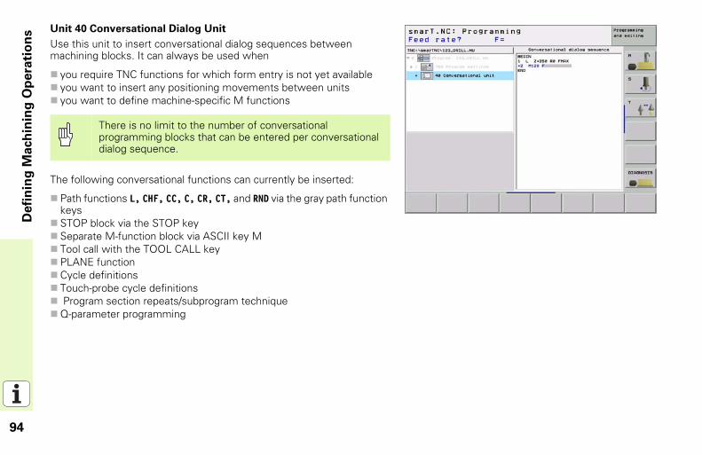
Unit 40 Conversational Dialog UnitUse this unit to insert conversational dialog sequences between machining blocks. It can always be used when
you require TNC functions for which form entry is not yet availableyou want to insert any positioning movements between unitsyou want to define machine-specific M functions
The following conversational functions can currently be inserted:
Path functions L, CHF, CC, C, CR, CT, and RND via the gray path function keysSTOP block via the STOP keySeparate M-function block via ASCII key MTool call with the TOOL CALL keyPLANE functionCycle definitionsTouch-probe cycle definitions Program section repeats/subprogram techniqueQ-parameter programming
There is no limit to the number of conversational programming blocks that can be entered per conversational dialog sequence.
95
Defi
nin
g M
ach
inin
g P
osit
ion
s
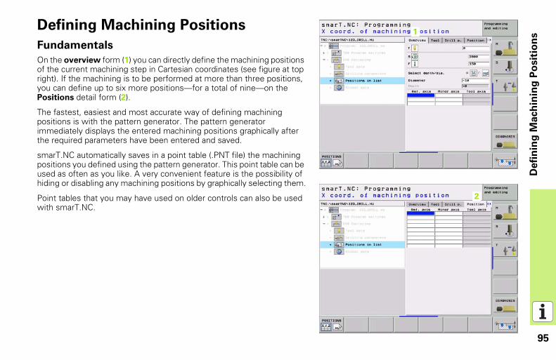
Defining Machining PositionsFundamentals
On the overview form (1) you can directly define the machining positions of the current machining step in Cartesian coordinates (see figure at top right). If the machining is to be performed at more than three positions, you can define up to six more positions—for a total of nine—on the Positions detail form (2).
The fastest, easiest and most accurate way of defining machining positions is with the pattern generator. The pattern generator immediately displays the entered machining positions graphically after the required parameters have been entered and saved.
smarT.NC automatically saves in a point table (.PNT file) the machining positions you defined using the pattern generator. This point table can be used as often as you like. A very convenient feature is the possibility of hiding or disabling any machining positions by graphically selecting them.
Point tables that you may have used on older controls can also be used with smarT.NC.
11
12

96
Defi
nin
g M
ach
inin
g P
osit
ion
s
Starting the pattern generator
The pattern generator for smarT.NC can be started two different ways:
Directly from the second soft-key row of the smarT.NC main menu, if you want to directly define several point files in a row.From the form during the machining definition, when you are supposed to enter machining positions.
Starting the pattern generator from the main row of the editing menu
Select the smarT.NC operating mode.
Select the second soft-key row.
Start the pattern generator: smarT.NC switches to the file manager (see figure at right) and shows any existing point files.Select an existing point file (*.PNT) and open it with the ENT key, or Create a new point file: Enter the file name (without file type), and confirm with the MM or INCH key. smarT.NC creates a point file with the units of measurement you selected, and then starts the pattern generator.
97
Defi
nin
g M
ach
inin
g P
osit
ion
s
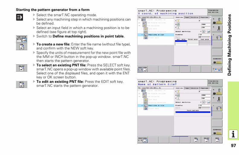
Starting the pattern generator from a form
Select the smarT.NC operating mode.Select any machining step in which machining positions can be defined.Select an input field in which a machining position is to be defined (see figure at top right).Switch to Define machining positions in point table.
To create a new file: Enter the file name (without file type), and confirm with the NEW soft key.Specify the units of measurement for the new point file with the MM or INCH button in the pop-up window. smarT.NC then starts the pattern generator.To select an existing PNT file: Press the SELECT soft key. smarT.NC opens a pop-up window with available point files. Select one of the displayed files, and open it with the ENT key or OK screen button.To edit an existing PNT file: Press the EDIT soft key. smarT.NC starts the pattern generator.
98
Defi
nin
g M
ach
inin
g P
osit
ion
s
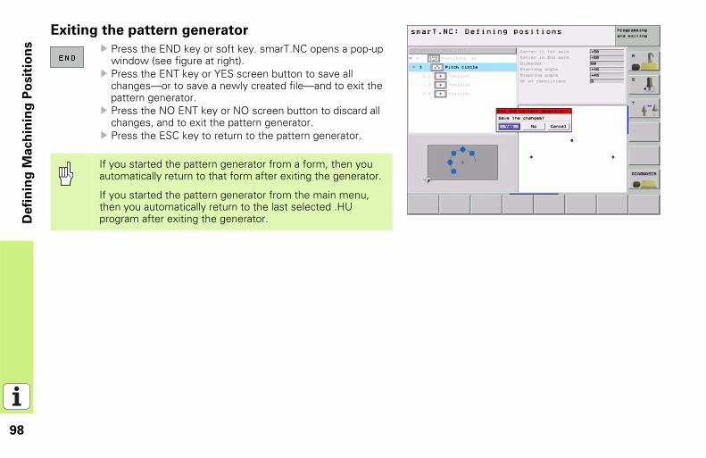
Exiting the pattern generator
Press the END key or soft key. smarT.NC opens a pop-up window (see figure at right).Press the ENT key or YES screen button to save all changes—or to save a newly created file—and to exit the pattern generator.Press the NO ENT key or NO screen button to discard all changes, and to exit the pattern generator.Press the ESC key to return to the pattern generator.
If you started the pattern generator from a form, then you automatically return to that form after exiting the generator.
If you started the pattern generator from the main menu, then you automatically return to the last selected .HU program after exiting the generator.
99
Defi
nin
g M
ach
inin
g P
osit
ion
s
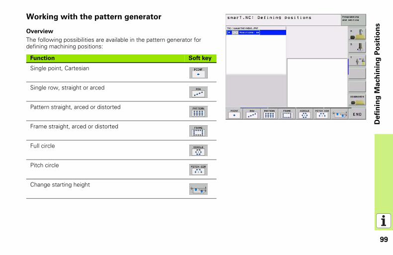
Working with the pattern generator
Overview
The following possibilities are available in the pattern generator for defining machining positions:
Function Soft key
Single point, Cartesian
Single row, straight or arced
Pattern straight, arced or distorted
Frame straight, arced or distorted
Full circle
Pitch circle
Change starting height
100
Defi
nin
g M
ach
inin
g P
osit
ion
s
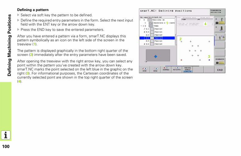
Defining a pattern
Select via soft key the pattern to be defined.Define the required entry parameters in the form. Select the next input field with the ENT key or the arrow down key.Press the END key to save the entered parameters.
After you have entered a pattern via a form, smarT.NC displays this pattern symbolically as an icon on the left side of the screen in the treeview (1).
The pattern is displayed graphically in the bottom right quarter of the screen (2) immediately after the entry parameters have been saved.
After opening the treeview with the right arrow key, you can select any point within the pattern you’ve created with the arrow down key. smarT.NC marks the point selected on the left blue in the graphic on the right (3). For informational purposes, the Cartesian coordinates of the currently selected point are shown in the top right quarter of the screen (4).
11
12
13
14
101
Defi
nin
g M
ach
inin
g P
osit
ion
s
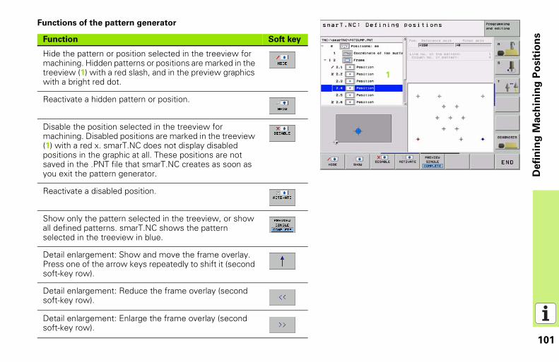
Functions of the pattern generator
Function Soft key
Hide the pattern or position selected in the treeview for machining. Hidden patterns or positions are marked in the treeview (1) with a red slash, and in the preview graphics with a bright red dot.
Reactivate a hidden pattern or position.
Disable the position selected in the treeview for machining. Disabled positions are marked in the treeview (1) with a red x. smarT.NC does not display disabled positions in the graphic at all. These positions are not saved in the .PNT file that smarT.NC creates as soon as you exit the pattern generator.
Reactivate a disabled position.
Show only the pattern selected in the treeview, or show all defined patterns. smarT.NC shows the pattern selected in the treeview in blue.
Detail enlargement: Show and move the frame overlay. Press one of the arrow keys repeatedly to shift it (second soft-key row).
Detail enlargement: Reduce the frame overlay (second soft-key row).
Detail enlargement: Enlarge the frame overlay (second soft-key row).
11
102
Defi
nin
g M
ach
inin
g P
osit
ion
s
Detail enlargement: Select marked area (second soft-key row).
Detail enlargement: Restore original section (second soft-key row).
Function Soft key
103
Defi
nin
g M
ach
inin
g P
osit
ion
s
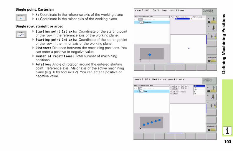
Single point, Cartesian
X: Coordinate in the reference axis of the working plane Y: Coordinate in the minor axis of the working plane
Single row, straight or arced
Starting point 1st axis: Coordinate of the starting point of the row in the reference axis of the working plane.Starting point 2nd axis: Coordinate of the starting point of the row in the minor axis of the working plane.Distance: Distance between the machining positions. You can enter a positive or negative value.Number of repetitions: Total number of machining positions.Rotation: Angle of rotation around the entered starting point. Reference axis: Major axis of the active machining plane (e.g. X for tool axis Z). You can enter a positive or negative value.
104
Defi
nin
g M
ach
inin
g P
osit
ion
s
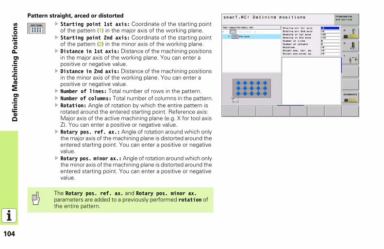
Pattern straight, arced or distorted
Starting point 1st axis: Coordinate of the starting point of the pattern (1) in the major axis of the working plane.Starting point 2nd axis: Coordinate of the starting point of the pattern (2) in the minor axis of the working plane.Distance in 1st axis: Distance of the machining positions in the major axis of the working plane. You can enter a positive or negative value.Distance in 2nd axis: Distance of the machining positions in the minor axis of the working plane. You can enter a positive or negative value.Number of lines: Total number of rows in the pattern.Number of columns: Total number of columns in the pattern.Rotation: Angle of rotation by which the entire pattern is rotated around the entered starting point. Reference axis: Major axis of the active machining plane (e.g. X for tool axis Z). You can enter a positive or negative value.Rotary pos. ref. ax.: Angle of rotation around which only the major axis of the machining plane is distorted around the entered starting point. You can enter a positive or negative value. Rotary pos. minor ax.: Angle of rotation around which only the minor axis of the machining plane is distorted around the entered starting point. You can enter a positive or negative value.
The Rotary pos. ref. ax. and Rotary pos. minor ax. parameters are added to a previously performed rotation of the entire pattern.
105
Defi
nin
g M
ach
inin
g P
osit
ion
s
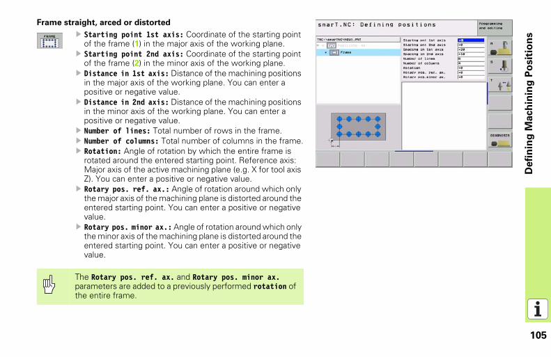
Frame straight, arced or distorted
Starting point 1st axis: Coordinate of the starting point of the frame (1) in the major axis of the working plane.Starting point 2nd axis: Coordinate of the starting point of the frame (2) in the minor axis of the working plane.Distance in 1st axis: Distance of the machining positions in the major axis of the working plane. You can enter a positive or negative value.Distance in 2nd axis: Distance of the machining positions in the minor axis of the working plane. You can enter a positive or negative value.Number of lines: Total number of rows in the frame.Number of columns: Total number of columns in the frame.Rotation: Angle of rotation by which the entire frame is rotated around the entered starting point. Reference axis: Major axis of the active machining plane (e.g. X for tool axis Z). You can enter a positive or negative value.Rotary pos. ref. ax.: Angle of rotation around which only the major axis of the machining plane is distorted around the entered starting point. You can enter a positive or negative value. Rotary pos. minor ax.: Angle of rotation around which only the minor axis of the machining plane is distorted around the entered starting point. You can enter a positive or negative value.
The Rotary pos. ref. ax. and Rotary pos. minor ax. parameters are added to a previously performed rotation of the entire frame.
106
Defi
nin
g M
ach
inin
g P
osit
ion
s
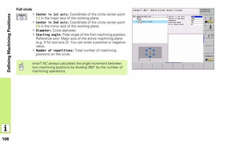
Full circle
Center in 1st axis: Coordinate of the circle center point (1) in the major axis of the working plane.Center in 2nd axis: Coordinate of the circle center point (2) in the minor axis of the working plane.Diameter: Circle diameter.Starting angle: Polar angle of the first machining position. Reference axis: Major axis of the active machining plane (e.g. X for tool axis Z). You can enter a positive or negative value.Number of repetitions: Total number of machining positions on the circle.
smarT.NC always calculates the angle increment between two machining positions by dividing 360° by the number of machining operations.
107
Defi
nin
g M
ach
inin
g P
osit
ion
s
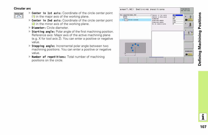
Circular arc
Center in 1st axis: Coordinate of the circle center point (1) in the major axis of the working plane.Center in 2nd axis: Coordinate of the circle center point (2) in the minor axis of the working plane.Diameter: Circle diameter.Starting angle: Polar angle of the first machining position. Reference axis: Major axis of the active machining plane (e.g. X for tool axis Z). You can enter a positive or negative value.Stepping angle: Incremental polar angle between two machining positions. You can enter a positive or negative value.Number of repetitions: Total number of machining positions on the circle.
108
Defi
nin
g M
ach
inin
g P
osit
ion
s
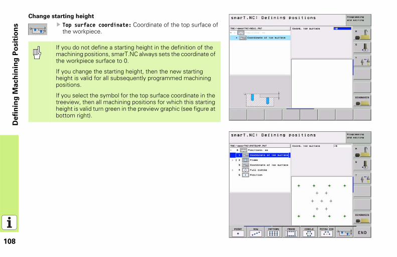
Change starting height
Top surface coordinate: Coordinate of the top surface of the workpiece.
If you do not define a starting height in the definition of the machining positions, smarT.NC always sets the coordinate of the workpiece surface to 0.
If you change the starting height, then the new starting height is valid for all subsequently programmed machining positions.
If you select the symbol for the top surface coordinate in the treeview, then all machining positions for which this starting height is valid turn green in the preview graphic (see figure at bottom right).

109
Defi
nin
g c
on
tou
rs
Defining contours
Fundamentals
Contours are defined in separate files (file type .HC). Since .HC files contain pure descriptions of contours—only geometry data, no technology data—they can be used flexibly: as contour trains, as pockets or as islands.
Existing contour descriptions in older plain-language programs (.H files) can easily be converted into smarT.NC contour descriptions (see page 116).
Just as with unit programs and the pattern generator, smarT.NC displays each contour element in the treeview (1) with an appropriate icon. Enter the data for each contour element in the form (2). In the FK free contour programming, along with the overview form (3) there are up to three additional detail forms (4) in which you can enter data (see figure at bottom right).
11
12
13 14
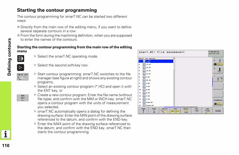
110
Defi
nin
g c
on
tou
rs
Starting the contour programming
The contour programming for smarT.NC can be started two different ways:
Directly from the main row of the editing menu, if you want to define several separate contours in a row.From the form during the machining definition, when you are supposed to enter the names of the contours.
Starting the contour programming from the main row of the editing menu
Select the smarT.NC operating mode.
Select the second soft-key row.
Start contour programming: smarT.NC switches to the file manager (see figure at right) and shows any existing contour programs.Select an existing contour program (*.HC) and open it with the ENT key, or Create a new contour program: Enter the file name (without file type), and confirm with the MM or INCH key. smarT.NC opens a contour program with the units of measurement you selected.smarT.NC automatically opens a dialog for defining the drawing surface: Enter the MIN point of the drawing surface referenced to the datum, and confirm with the END key.Enter the MAX point of the drawing surface referenced to the datum, and confirm with the END key. smarT.NC then starts the contour programming.
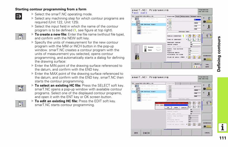
111
Defi
nin
g c
on
tou
rs
Starting contour programming from a form
Select the smarT.NC operating mode.Select any machining step for which contour programs are required (Unit 122, Unit 125).Select the input field in which the name of the contour program is to be defined (1, see figure at top right).To create a new file: Enter the file name (without file type), and confirm with the NEW soft key.Specify the units of measurement for the new contour program with the MM or INCH button in the pop-up window. smarT.NC creates a contour program with the units of measurement you selected, opens contour programming, and automatically starts a dialog for defining the drawing surface:Enter the MIN point of the drawing surface referenced to the datum, and confirm with the END key.Enter the MAX point of the drawing surface referenced to the datum, and confirm with the END key. smarT.NC then starts the contour programming.To select an existing HC file: Press the SELECT soft key. smarT.NC opens a pop-up window with available contour programs. Select one of the displayed contour programs, and open it with the ENT key or OK screen button.To edit an existing HC file: Press the EDIT soft key. smarT.NC starts contour programming.
11
112
Defi
nin
g c
on
tou
rs
Exiting the contour programming
Press the END key: smarT.NC exits the contour programming and returns to the state from which you started contour programming: Either to the last active .HU program, if you started from the smarT.NC main row, or to the entry form of the machining step, if you started from the form.
If you started contour programming from a form, then you automatically return to that form after exiting the generator.
If you started contour programming from the main menu, then you automatically return to the last selected .HU program after exiting the programming.
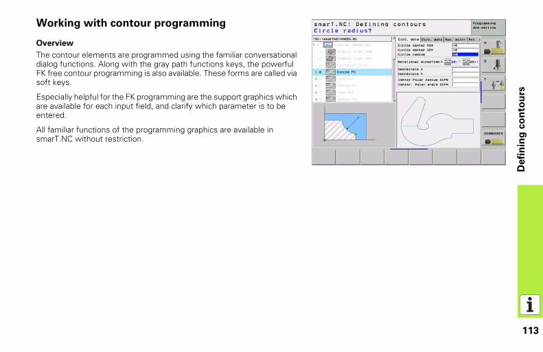
113
Defi
nin
g c
on
tou
rs
Working with contour programming
Overview
The contour elements are programmed using the familiar conversational dialog functions. Along with the gray path functions keys, the powerful FK free contour programming is also available. These forms are called via soft keys.
Especially helpful for the FK programming are the support graphics which are available for each input field, and clarify which parameter is to be entered.
All familiar functions of the programming graphics are available in smarT.NC without restriction.
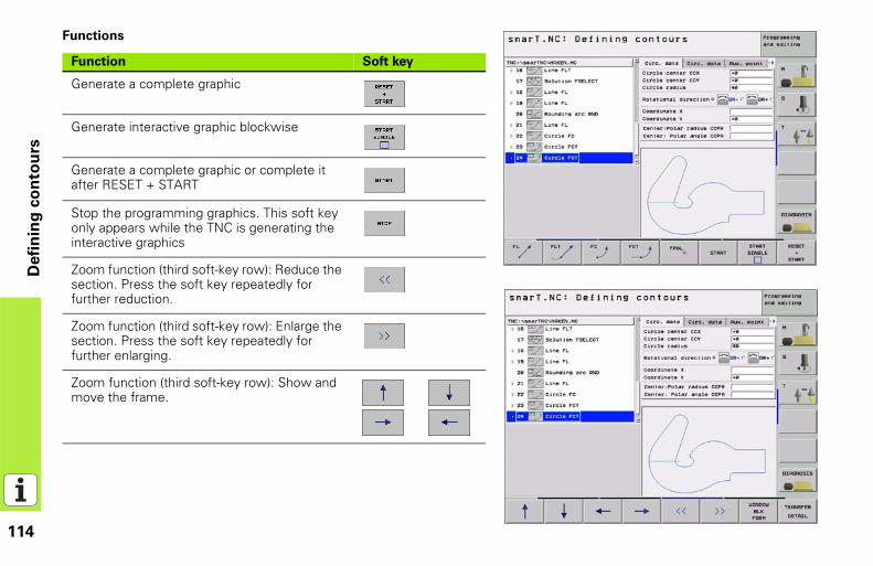
114
Defi
nin
g c
on
tou
rs
Functions
Function Soft key
Generate a complete graphic
Generate interactive graphic blockwise
Generate a complete graphic or complete it after RESET + START
Stop the programming graphics. This soft key only appears while the TNC is generating the interactive graphics
Zoom function (third soft-key row): Reduce the section. Press the soft key repeatedly for further reduction.
Zoom function (third soft-key row): Enlarge the section. Press the soft key repeatedly for further enlarging.
Zoom function (third soft-key row): Show and move the frame.
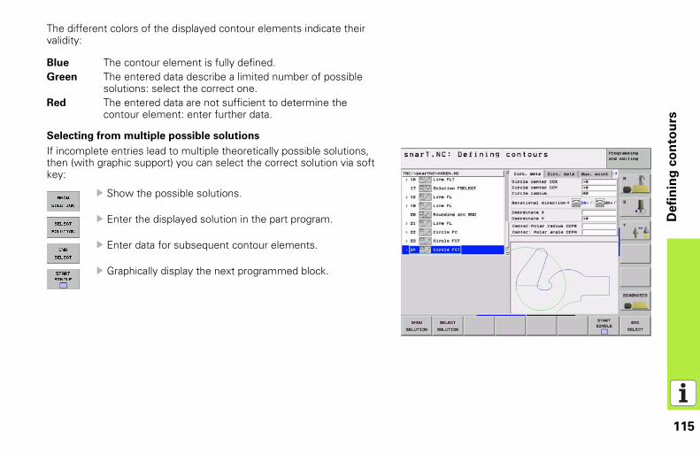
115
Defi
nin
g c
on
tou
rs
The different colors of the displayed contour elements indicate their validity:
Selecting from multiple possible solutions
If incomplete entries lead to multiple theoretically possible solutions, then (with graphic support) you can select the correct solution via soft key:
Show the possible solutions.
Enter the displayed solution in the part program.
Enter data for subsequent contour elements.
Graphically display the next programmed block.
Blue The contour element is fully defined.Green The entered data describe a limited number of possible
solutions: select the correct one.Red The entered data are not sufficient to determine the
contour element: enter further data.
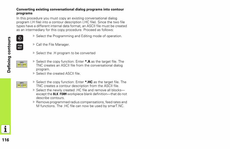
116
Defi
nin
g c
on
tou
rs
Converting existing conversational dialog programs into contour programs
In this procedure you must copy an existing conversational dialog program (.H file) into a contour description (.HC file). Since the two file types have a different internal data format, an ASCII file must be created as an intermediary for this copy procedure. Proceed as follows:
Select the Programming and Editing mode of operation.
Call the File Manager.
Select the .H program to be converted
Select the copy function: Enter *.A as the target file. The TNC creates an ASCII file from the conversational dialog program.Select the created ASCII file.
Select the copy function: Enter *.HC as the target file. The TNC creates a contour description from the ASCII file.Select the newly created .HC file and remove all blocks—except the BLK FORM workpiece blank definition—that do not describe contours.Remove programmed radius compensations, feed rates and M functions. The .HC file can now be used by smarT.NC.
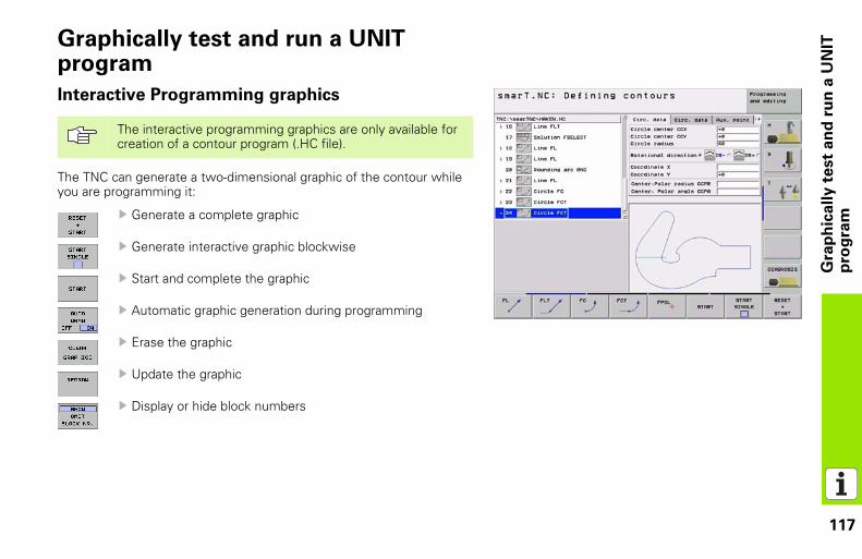
117
Gra
ph
ica
lly
te
st
an
d r
un
a U
NIT
p
rog
ram
Graphically test and run a UNIT program
Interactive Programming graphics
The TNC can generate a two-dimensional graphic of the contour while you are programming it:
Generate a complete graphic
Generate interactive graphic blockwise
Start and complete the graphic
Automatic graphic generation during programming
Erase the graphic
Update the graphic
Display or hide block numbers
The interactive programming graphics are only available for creation of a contour program (.HC file).
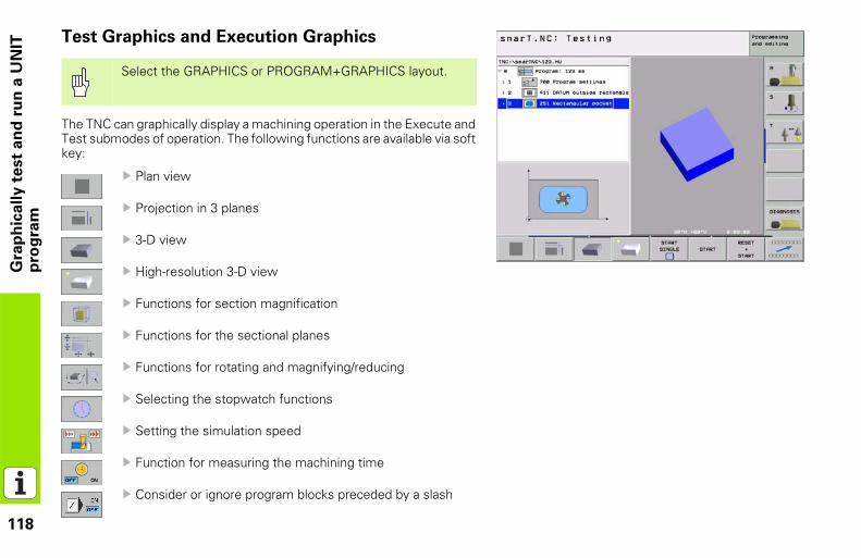
118
Gra
ph
ica
lly
te
st
an
d r
un
a U
NIT
p
rog
ram
Test Graphics and Execution GraphicsThe TNC can graphically display a machining operation in the Execute and Test submodes of operation. The following functions are available via soft key:
Plan view
Projection in 3 planes
3-D view
High-resolution 3-D view
Functions for section magnification
Functions for the sectional planes
Functions for rotating and magnifying/reducing
Selecting the stopwatch functions
Setting the simulation speed
Function for measuring the machining time
Consider or ignore program blocks preceded by a slash
Select the GRAPHICS or PROGRAM+GRAPHICS layout.
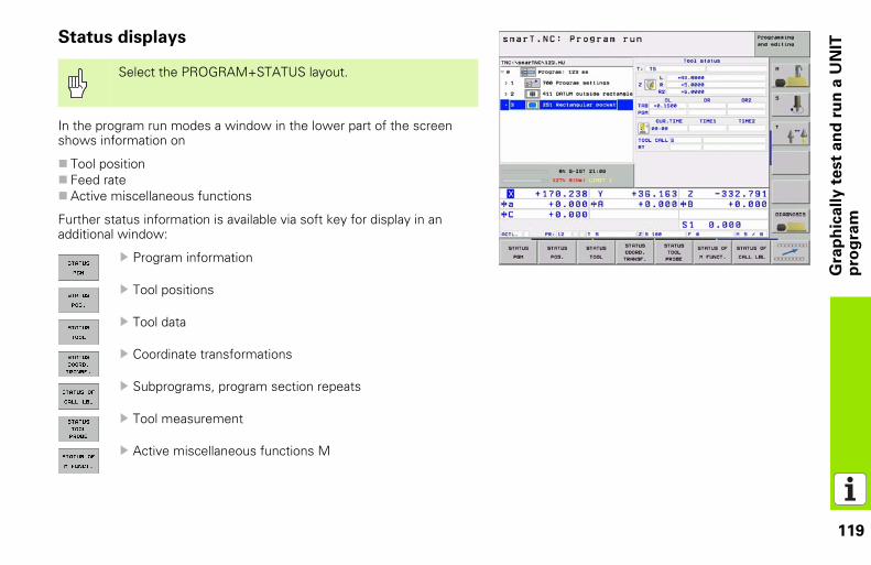
119
Gra
ph
ica
lly
te
st
an
d r
un
a U
NIT
p
rog
ram
Status displays
In the program run modes a window in the lower part of the screen shows information on
Tool positionFeed rateActive miscellaneous functions
Further status information is available via soft key for display in an additional window:
Program information
Tool positions
Tool data
Coordinate transformations
Subprograms, program section repeats
Tool measurement
Active miscellaneous functions M
Select the PROGRAM+STATUS layout.
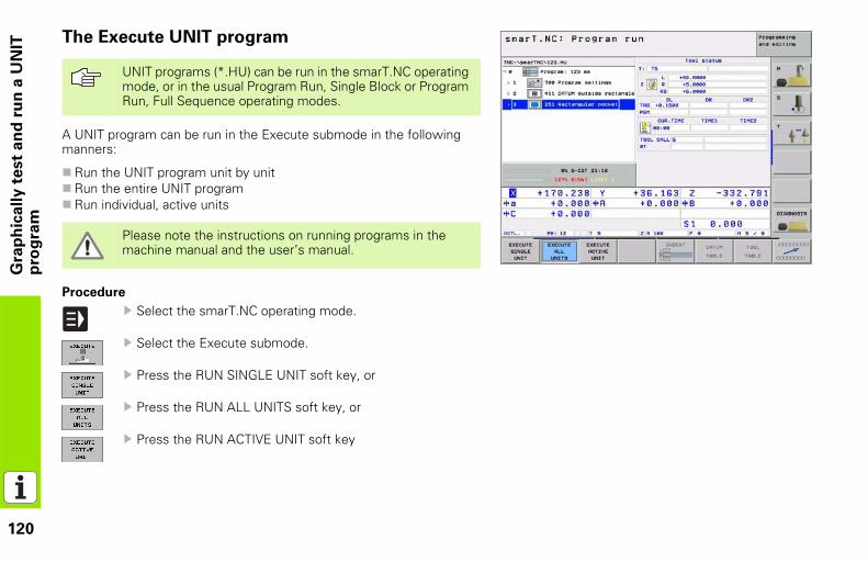
120
Gra
ph
ica
lly
te
st
an
d r
un
a U
NIT
p
rog
ram
The Execute UNIT programA UNIT program can be run in the Execute submode in the following manners:
Run the UNIT program unit by unitRun the entire UNIT programRun individual, active units
Procedure
Select the smarT.NC operating mode.
Select the Execute submode.
Press the RUN SINGLE UNIT soft key, or
Press the RUN ALL UNITS soft key, or
Press the RUN ACTIVE UNIT soft key
UNIT programs (*.HU) can be run in the smarT.NC operating mode, or in the usual Program Run, Single Block or Program Run, Full Sequence operating modes.
Please note the instructions on running programs in the machine manual and the user’s manual.
Ve00533 191-20 · SW01 · 30 · 11/2004 · Bi������������������ �����������������������������������
��������������� ����������������������� ������������������������������� ���� ����� ���������� ��� ��������! ����
����������������� �������������� ��� ������������������������� ������� ���������������� ������������������ � � !�"� ��� ��
�������� �!�""#�� � ��������������������� � ���# $"� ��� ��
$��!����%�!�!���! � ��������������������� � ���# $�����%&&���"� ��� ��
�&�!�""#�� � ��������������������� � ���# $�$��%&&���"� ��� ��
&�"�#%������% � ��������������������� � ���# $�$�&'�"� ��� ��
'(&�"�#%������% � �����������������(��� � ���# $�&�$"� ��� ��
(������#���# ! � �����)������(�������� � ���# $���!"� ��� ��
***�� ��� ��