Embed Size (px)
Citation preview


MONTAGGIO DELLA CREMAGLIERA- Sbloccare il pignone girando la manopola come in figura 4 e pro-
cedere al montaggio della cremagliera come segue:- Saldare la cremagliera ad un angolare (fig. 5) che serve da spes-
sore ed evita inconvenienti derivanti da possibili curvature delcancello.N.B.: Per mantenere corretto il passo della cremagliera durante lagiunzione degli spezzoni, posizionare un moncone di cremaglieratra uno spezzone e l’altro (fig. 6).
- Appoggiare la parte iniziale dell’elemento di cremagliera al pigno-ne dentato P ed effettuarne il fissaggio al cancello con un brevetratto di saldatura (fig. 7) da eseguire nel punto dell’angolaresituato sopra il pignone: fare scorrere manualmente il cancellocompletamente e ripetere la stessa operazione anche per la partefinale dell’elemento di cremagliera: la cremagliera dovrà restarecostantemente appoggiata al pignone. Eseguire altri cordoni disaldatura per fissare completamente la cremagliera al portone.
INSTALLATION OF THE RACK- Release the pinion by turning the knob as in Figure 4 and carry
out the installation of the rack as follows:- Weld the rack to an angle bar (Fig. 5) which acts as a shim and
prevents inconveniences caused by bends in the gate.Note: To maintain correct rack pitch during the connection of thebars, place a rack piece between one bar end and another (Fig. 6).
- Rest the initial part of the rack on the toothed pinion P and welda short stretch of the rack to the gate (Fig. 7) at the point in theangle bar over the pinion: manually slide the gate across comple-tely and repeat the same procedure for the final part of the rack:the rack should be resting at all times over the pinion. Weldfurther seams to fix the rack completely to the gate.
MONTAGE DE LA CREMAILLERE- Dégager le pignon en tournant la poignée comme illustré dans la
figure 4 et monter la crémaillère comme suit:- Souder la crémaillère à un angle (fig. 5) qui servira de cale et évitera
les inconvénients dérivant des possibles cambrages du portail.N.B. Pour maintenir le pas exact de la crémaillère pendant lajonction des tronçons, positionner un bout de crémaillère entreun tronçons et l'autre (fig. 6).
- Poser la partie initiale de l'élément de crémaillère au pignondenté P et fixer le tout au portail avec une courte soudure (fig. 7)à effectuer dans le point de l’angle situé au-dessus du pignon;faire coulisser manuellement le portail pour toute sa course etrépéter cette même opération aussi pour la partie finale de l'élé-ment de crémaillère; la crémaillère devra toujours rester posée aupignon. Effectuer d'autres cordons de soudure pour fixer com-plètement la crémaillère au portail.
MONTAGE DER ZAHNSTANGEFür eine korrekte Montage der Zahnstange wie folgt vorgehen:- Entriegeln des Antriebszahnrades (Abb. 4):- Zahnstange an einen Winkel schweißen (Abb. 5). Bei der
Montage der Zahnstangenelemente ist unbedingt darauf zu ach-ten, daß an den Übergängen die Abstände für dasAntriebszahnrad eingehalten werden. Dies erreicht man am ein-fachsten, indem man bei der Montage ein Zahnstangenelementvon der Unterseite am Übergang einrastet (Abb. 6).
- Anfangsteil des Zahnstangenelementes auf das Zahnritzel P aufle-gen und durch eine kleine Schweißung am Tor befestigen (Abb. 7).
- Tor von Hand die ganze Strecke laufen lassen und gleicheOperation mit dem Endteil des Zahnstangenelementes wiederho-len. Die Zahnstange muß dabei immer auf das Ritzel aufgelegt sein.
- Weitere Schweißnähte ausführen, um die Zahnstange vollständigam Tor zu befestigen.
- Zahnstange leicht fetten.- Zahnrad wieder verriegeln und Probelauf durchführen.Bei korrekter Montage läuf das Tor sehr leise und ruckfrei. Die vonuns gelieferte Zahnstangen CFZ haben eine Länge von 2 m. Wirverfügen auch über Zahnstangen CVZ die eine Länge von 1 mhaben. Sie verfügen bereits über Langlöcher, welche dieHöhenanpassung der Zahnstange zum Antrieb wesentlich erleich-tern. Verwenden Sie unbedingt die mitgelieferten Distanzhülsenzwischen Zahnstange und Torholm.
MONTAJE DE LA CREMALLERA- Desbloquear el piñón girando el pomo como se indica en la figu-
ra 4 y montar la cremallera de la siguiente manera:- Soldar la cremallera a un hierro angular (fig. 5) que sirve como
espesor y evita inconvenientes derivados de posibles curvaturasde la verja.N.B. Para permitir que el paso de la cremallera se mantengauniforme en la zona de empalme, colocar un trozo de cremallerainvertido como se indica en la (fig. 6) entre una y otra parte decremallera.
- Apoyar la parte inicial del elemento de cremallera al piñón denta-do P y fijarlo a la verja con una soldadura corta (fig.. 7) que deberealizarse en el punto del hierro angular situado sobre el piñón:desplazar manualmente la verja, por completo, y repetir la mismaoperación tambien para la parte final del elemento de cremallera;la cremallera deberá permanecer constantemente apoyada alpiñón. Realizar otros cordones de soldadura para fijar completa-mente la cremallera al portón.
I
GB
F
D
E
FIG. 4/I°
FIG. 4/II°
FIG. 6
FIG. 7
4

POSIZIONAMENTO DEL PIGNONEAd operazione ultimata eseguire la regolazione del motoriduttorein modo di consentire un gioco di circa 2 mm fra pignone e crema-gliera. Effettuare l’allineamento orizzontale del pignone spostandoil motoriduttore lungo le apposite feritoie previste nella base (fig. 8)in modo che il pignone sia a contatto con la cremagliera per tuttala larghezza del dente pignone (fig. 8/a).
POSITIONING OF THE PINIONWhen this operation is complete, adjust the gearmotor to allow aplay of 2 mm approx. between the pinion and the rack. Align thepinion horizontally moving the gearmotor along the special slots inthe base (Fig. 8) so that the pinion is in contact with the rack alongthe whole width of the pinion tooth (Fig. 8/a).
POSITIONNEMENT DU PIGNONUne fois cette opération terminée, effectuer le réglage du motoré-ducteur de façon à permettre un jeu de 2 mm environ entre lepignon et la crémaillère. Effectuer l'alignement horizontal dupignon en déplaçant le motoréducteur le long des fentes spéciales
prévues dans la base (fig. 8) de telle façon que le pignon soit àcontact avec la crémaillère pour toute la largeur de la dent dupignon (fig. 8/a).
POSITIONIERUNG DES RITZELSNachdem die Zahnstangen angebracht sind, wird eineUnterlegscheibe pro Befestigungsschraube entfernt, um ein Spielvon ca. 2 mm zu erreichen. Es ist ratsam einige Unterlegscheibenan ihrem Platz zu belassen, damit der Antrieb bei einem Absenkendes Tores noch nachjustiert werden kann. Die Langlöcher (Abb. 8)dienen der genauen Einstellung des Zahnritzels zur Zahnstange.Die Zähne des Ritzels, bzw. die Zähne der Zahnstange sollten aufIhrer ganzen Breite im Eingriff sein (Abb. 8/a).
COLOCACION DEL PIÑONConcluida la operación, regular el motorreductor de tal maneraque entre el piñón y la cremallera exista un juego de aproximada-mente 2 mm. Alinear horizontalmente el piñón desplazando elmotorreductor a lo largo de las correspondientes rendijas previ-stas en la base (fig. 8) para que el piñón esté en contacto con lacremallera a todo lo ancho del diente piñón (fig. 8/a).
I
GB
F
D
E
FIG. 8/a
FIG. 7
5

MONTAGGIO STAFFE FINECORSAFissare alla cremagliera le due staffe di arresto chiusura ed apertu-ra mediante gli appositi grani di bloccaggio (fig. 9). Posizionare lestaffe di fronte alla leva di comando dei micro (L) rispettivamentecon cancello aperto e chiuso (fig. 10).IMPORTANTE: il fermo di arresto (fig. 11) deve essere posizionatoin modo tale che in ogni caso la staffa del fine corsa, non si scontrimai con il pignone.Lasciare un franco di sicurezza di circa 50 mm fra il cancello ed ilbattente fisso come previsto dalle norme di sicurezza (fig. 11/a).
INSTALLATION OF END OF STROKE BRACKETSFasten the two closing and opening end of stroke brackets to therack using the special locking dowels (Fig. 9). Place the brackets infront of the control lever of the microswitches (L) respectively withgate open and gate closed (Fig. 10).IMPORTANT: the gate backstop (Fig. 11) must be positioned insuch way that the end of stroke bracket never comes into contactwith the pinion.Leave a distance of abt. 50 mm between the gate and fixedstop as per current safety standards (fig. 11/a).
MONTAGE DES ETRIERS DES FIN DE COURSEFixer à la crémailläre les deux étriers d’arrêt fermeture et ouvertureau moyen les vis de fixation sans tête (fig. 9). Positionner lesétriers face au levier de commande des microcontacts (L) respecti-vement avec le portail ouvert et fermé (fig. 10).IMPORTANT: l’arrêt (fig. 11) doit etre positionné de telle façon queen tous les cas l’étrier de la fin de course ne se heurte jamais con-tre le pignon.Laisser une distance de sécurité d’environ 50 mm entre le portailet la butée fixe, conformément aux normes de sécurité (fig. 11/a).
MONTAGE DER ENDSCHALTERNOCKENDie Endschalternocken für Tor-Auf und Tor-Zu können stufenlosmit je 2 Klemmschrauben an der Zahnstange justiert werden. (Abb.9). Sie betätigen den Endschalter L am Antrieb. (Abb. 10).WICHTIG: Achten Sie darauf, daß der Auflaufbock (Abb. 11) sopositioniert ist, daß der Bügel des Endschalternockens auf keinenFall an das Antriebsritzel stößt.Lassen Sie zwischen dem Tor und dem Auflaufbock einenSichereitsabstand von ca. 50 mm., wie es von denSicherheitsnormen vorgeschrieben wird (Abb. 11/a).
MONTAJE DE LOS PERNOS DE FIN DE CARRERAAjustar en la cremallera los dos pernos de tope de cierre y apertu-ra mediante las espigas de sujeción ( fig. 9). Colocar los pernos defrente a la palanca de control de los microinterruptores (L) quecorresponden respectivamente a verja abierta y cerrada (fig. 10).IMPORTANTE: el tope de parada (fig. 11) debe estar colocado demodo tal que los pernos de fin de carrera no se choquen enningún caso con el piñón.Dejar una distancia de seguridad de aproximadamente 50 mm.entre la verja y el tope fijo, tal como disponen las normas deseguridad (fig. 11/a).
I
GB
F
D
E
FIG. 9
FIG. 10
FIG. 11 FIG. 11/a
6
PREDISPOSIZIONE DELL’IMPIANTO ELETTRICO
SCHEMA GENERALE
I) Interruttore generale di linea con fusibili di protezione da5A.
L) Lampeggiante con antennaM) MotoriduttoreD) Scatola di derivazioneA) Antenna con cavo caossialeS) Selettore a chiave da fissare nella facciata esterna del
pilastro.P) Pulsantiera da interno, per più pulsanti collegare in paral-
lelo.FTi-Fte) Fotocellula trasmittente interna ed esterna da fissare ad
una altezza compresa tra 40 e 60 cm.FRi-FRe) Fotocellule riceventi interna ed esterna da fissare ad una
altezza compresa tra 40 e 60 cm.Pa) Pressostato per costa pneumatica di apertura.Pc) Pressostato per costa pneumatica di chiusura.
N.B.: la sezione e il numero di fili é indicata nel disegno (fig. 12).Per lunghezze superiori a 100 mt. aumentare la sezione deifili.
- Tutte le masse metalliche dei contenitori delle apparecchiature edegli automatismi devono esser messe a terra.
- Le fotocellule e i pressostati devono essere collegati tra loro inserie con contatto normalmente chiuso.
ELECTRICAL SYSTEM WIRING DIAGRAM
GENERAL WIRING DIAGRAM
I) Main circuit breaker with 5 A protection fuses.L) Flasher with antennaM) Reduction gear unitD) Junction boxA) Antenna coaxial cableS) Key switch must be mounted on exterior of gate post.P) Pushbutton panel for interior mounting - extra panels can
be connected in parallel.FTi-Fte) Interior and exterior photoelectric cell transmitter, must
be mounted at a heigh between 40 and 60 cm.FRi-FRe) Interior and exterior photoelectric cell receiver, must be
mounted at a height between 40 and 60 cm.Pa) Pressure switch for pneumatic skirting (open phase).Pc) Pressure switch for pneumatic skirting (close phase).
N.B.: the gage and number of wires is indicated on drawing infigure 12 - for lenghts greater than 100 m. increase gage ofwire.
- All ground wires of all equipment and casing must be grounded.- The photoelectric cells and the pressure switches must be con-
nected together in series with contact normally closed.
GBI
FIG. 12
7

PREDISPOSITION IMPLANTATION ELECTRIQUE
SCHEMA GENERAL
I) Interrupteur général de ligne avec fusible de 5A.L) Lampe clignotante avec antenne.M) Motoréducteur.D) Boite de dérivation.A) Antenne avec cable coaxiale.S) Sélecteur à clé à fixer sur la façade externe du pilier.P) Boite à bouton interne, pour plusieurs boutons raccorder
en parallèl.FTi-Fte) Photocellule emetteur interne et externe à fixer à une
hauteur comprise entre 40 et 60 cm.FRi-FRe) Photocellule réceptrice interne et externe à fixer à une
houteur comprise entre 40 et 60 cm.Pa) Pressostat pour barre palpeuse pneumatique d’ouverture.Pc) Idem de fermeture.
N.B.: La section et le nombre de fils et indiqué dans le dessin (fig.12) pour une longueur supérieure à 100 Mt; augmenter lasection des fils.
- Toutes les masses métalliques des coffrets et des moteurs doi-vent être raccordées à la terre.
- Les photocellules et les préssostats doivent être raccordés entreeux en série avec contacts normalement fermés.
BEZEICHNUNG DER ELEKTRISCHEN ELEMENTE DESINSTALLATIONSPLANES:
I) Zuleitung mit Motorschutzschalter.L) Blinkleuchte.M) Schiebetorantrieb.D) Abzweigdose.S) Schlüsselschalter.P) Drucktaster innen.FTi-Fte) Lichtschranken, Sender und Empfänger.FRi-FRe) Lichtschranken, Sender und Empfänger.Pa) Überwachungseinheit für Sicherheitsleiste - Öffnung.Pc) Überwachungseinheit für Sicherheitsleiste - Schliessung.
N.B.: Der Querschnitt und die Anzahl der Kabel sind in derZeichnung (Abb. 12) angegeben, bei Längen über 100 m.den Kabelquerschnitt erhöhen.
- Alle metallischen Massen der Behälter der Apparaturen und derAutomatismen müssen geerdet werden.
- Die Photozellen und die Sicherheitskontaktleisten müssen miteinem normalerweise geschlossenen Kontakt untereinanderseriengeschaltet werden.
PREDISPOSICION DEL SISTEMA ELECTRICO
ESQUEMA GENERAL
I) Interruptor general de línea con fusibles de protección de 5 A.L) Luz intermitente con antena.M) Motorreductor.D) Caja de derivación.A) Antena con cable coaxial.S) Selector con llave que se debe fijar en la parte delantera.P) Botonera con botón interior, para varios pulsos conecta-
dos paralelamente.FTi-Fte) Fotocélula transmisora interior y exterior que se debe
fijar entre los 40 e 60 cm. de altura.FRi-FRe) Fotocelulas de recepción interior que se debe fijar entre
los 40 y los 60 cm. de altura.Pa) Presostato para costa neumática de abertura.Pc) Presostato para costa neumática de cierre.
N.B.: la sección y el número de los cables están indicados en eldibujo (fig. 12), en caso de una distancia superiore a los 100metros, aumentar la sección de los cables.
- Todas las masas metálicas de las cajas y de los motores debenser conectadas a tierra.
- Las fotocélulas y los presostatos deben ser conectados en seriecon el contacto normalmente cerrado.
F
D
E
8

COLLEGAMENTO ALLA MORSETTIERA1-2 Alimentazione 220V+/- 10% 50/60 Hz (collegare il neutro al morsetto 2).3-4-5 Collegamento motore 220V, morsetti 3-5 marcia motore, 4 comune.3-6 Collegamento condensatore.2-7 Uscita 220V per lampeggiante.8-9 Pulsante Start N.A.8-10 Pulsante Blocco N.C.. Se non si utilizza lasciare il ponticello inserito8-11 Contatto fotocellula, N.C.8-12 Fine corsa di apertura, N.C.8-13 Fine corsa di chiusura, N.C.14-15 Uscita 24V ac max 5W per alimentazione fotocellula ed altri dispositivi15-16 Uscita 24V ac, max 3W per spia cancello aperto. Con cancello chiuso la spia rimane spenta. Con cancello aper-
to od in fase di apertura la spia si accende. Durante la fase di chiusura la spia lampeggia.17-18 Collegamento antenna, 17 segnale, 18 schermoCOLLEGAMENTO MORSETTIERA SCHEDA OPTIONAL19-20 Pulsante apre, N.A. al comando di “apre” il motore apre qualsiasi sia il suo stato.19-21 Pulsante chiude, N.A. al comando di “chiude” il motore chiude qualsiasi sia il suo stato.19-22 Pulsante pedonale, N.A. al comando di pedonale il cancello apre per circa 1 metro.23-24 Ingresso contatto costa pneumatica o ad infrarossi N.C. all’apertura di questo contatto il cancello inverte per
circa 30 cm. ponticellare questi 2 morsetti se non vengono usati.25-26 Uscita secondo canale radio (se inserita una scheda bicanale).
TERMINAL BOARD CONNECTION1-2 220V power supply +/- 10% 50/60 Hz. Connect the neutral wire to terminal 2.3-4-5 Motor connection 220 V, common terminal 4, terminals 3 and 5 for motor running.3-6 Capacitor connection.2-7 220V Output per blinking light.8-9 Start button, N.O.8-10 Block button, N.C. If is not used provide with a jumper.8-11 Photoelectric cell contact, N.C.8-12 Opening limit switch, N.C.8-13 Closing limit switch, N.C.14-15 24V AC output, max 5W for energizing photoelectric cells and other devices.15-16 24V AC output, max 3W for open gate indicator light. When gate is closed the indicator light stays off. When
gate is open or in opening phase the indicator light turns on. During the closing phase the indicator light fla-shes.
17-18 Antenna connection, 17 signal, 18 shieldCONNECTION OF OPTIONAL BOARD TO TERMINALS19-20 Opening, N.A., when the “open” command is activated the motor starts opening no matter what its position is.19-21 Closing, N.A. when the “close” command is activated the motor starts closing no matter what its position is.19-22 Push button for pedestrian access, N.A. when the pedestrian opening is activated the gate opens for about 1
metre.23-24 Input of rubber/infrared skirt contact, N.C. when this contact is opened, the gate reverses the direction for ABT.
30 cm. If these two terminals are not used, provide them with a jumper.25-26 Second radio channel output, if twin-channel receiver is mounted.
CONNEXION DE LA PLAQUE A BORNES1-2 Alimentation 220V +/- 10% 50/60 Hz. Connecter la neutre à la borne 2.3-4-5 Connexion moteur borne 4 commune, bornes 3 et 5 marche moteur.3-6 Connexion condensateur.2-7 Sortie 220V pour feu clignotant.8-9 Bouton-poussoir de start, N.O.8-10 Bouton-poussoir de blocage, N.F. S’il n’esp pas utilisé, laissez le pontet inseré.8-11 Contact photocellule N.F.8-12 Fin de course ouverture, N.F.8-13 Fin de course fermeture, N.F.14-15 Sortie 24V c.a. maxi 5 W pour alimentation photocellules et autres dispositifs15-16 Sortie 24 V c.a. maxi 3 W pour témoin lumineux portail ouvert. Avec portail fermé, le témoin reste éteint. Avec
portail ouvert ou dans la phase d’ouverture, le témoin s’allume. Pendant la phase de fermeture, le témoin cli-gnote.
17-18 Connexion antenne, 17 signal, 18 blindage.CONNEXION PLAQUE A BORNES CARTE EN OPTION19-20 Bouton-poussoir ouvre, N.O. A la commande de “ouvre”, le moteur ouvre quel que soit son état.19-21 Bouton-poussoir ferme, N.O. A la commande de “ferme”, le moteur ferme quel que soit son état.19-22 Bouton-poussoir entrée pietons, N.O. A la commande de “entrée pietons”, le portail ouvre pour 1 mètre envi-
ron.23-24 Entrée contact barre palpeuse pneumatique ou à rayons infrarouges N.F. A l’ouverture de ce contact, le portail
inverse le mouvement pour 30 cm environ. Effectuer un pontet sur ces 2 bornes si elles ne sont pas utilisées.25-26 Sortie deuxième canal, si une carte receptrice bicanale est montée.
ANSCHLUSS KLEMMBRETT1-2 Versorgung 220V+/- 10% 50/60 Hz den Nulleiter an Klemme 2 anschließen.3-4-5 Motoranschluß, Klemme 4 gemeinsam, Klemme 3 und 5 Motorbetrieb.3-6 Kondensator-Anschluß2-7 Ausgang 220V für Blinkleuchte8-9 Startknopf, N.O.8-10 Fotozellenkontakt, N.C.8-11 Fotozellenkontakt, N.C.8-12 Endschalter Öffnung, N.C.8-13 Endschalter Schließung, N.C.14-15 Ausgang 24V AC, max 5 W zur Versorgung von Fotozellen oder anderer Vorrichtungen15-16 Ausgang 24V AC, max 3 für Kontrolleuchte Tor geöffnet. Bei geschlossenem Tor bleibt die Kontrolleuchte
ausgeschaltet. Bei geöffnetem Tor oder in der Öffnungsphase schaltet sich die Kontrolleuchte ein. In derSchließphase blinkt die Kontrolleuchte.
17-18 Antennenanschluß 17 Signal - 18 Abschirm kabel.ANSCHLUSS KLEMMBRETT OPTIONALKARTE19-20 Druckknopf “öffnet” N.O.; Bei Betätigung des Druckknopf "öffnet”, öffnet sich der Motor, unabhängig davon, in
whelchem Zustand er ist.19-21 Druckknopf “schließt” N.O.; Bei Betätigung des Druckknopf “schließt”, schließt sich der Motor, unabhängig
davon, in welchem Zustand er ist.19-22 Druckknopf “Fußgänger” N.O.; Bei Betätigung des Druckknopf “Fußgänger”, öffnet sich der Motor um ca. 1
Meter.23-24 Eingang Kontakt Sicherheits- oder Infrarotleiste N.C.; Bei Öffnung dieses Kontaktes kehrt das Tor für ca. 30 cm.
um. Diese beiden Klemmen überbrücken, wenn nicht benutzt.25-26 Ausgang zweiter Kanal, wenn eine Zwei-Kanal-Empfängerkarte montiert ist.
CONNEXION DEL TABLERO DE BORNES1-2 Alimentación 220V+/- 10% 50/60 Hz. Conectar el neutro al borne 2.3-4-5 Conexión motor borne 4 común, bornes 3 y 5 marcha motor.3-6 Conexión condensador2-7 Salida 220 V para luz de destello8-9 Botón start, N.A.8-10 Botón bloqueo, N.C.8-11 Contacto fotocélula N.C.8-12 Fin de carrera apertura, N.C.8-13 Fin de carrera cierre, N.C.14-15 Salida 24V corriente alterna máx. 3W, para alimentar fotocélulas u otros dispositivos.15-16 Salida 24 V corriente alterna, máx. 3W para luz indicadora verja abierta. Cuando la verja está cerrada, la luz
indicadora permanece apagada. Cuando la verja está abierta o en fase de apertura, la luz indicadora se encien-de. En fase de cierre, la luz indicadora destella intermitentemente.
17-18 Conexión antena, 17 señal, 18 trenza.CONEXION DEL TABLERO DE BORNES FICHA OPCIONAL19-20 Botón abre, N.A. Con el mando de “abre”, el motor abre la verja, cualquiera sea su estado.19-21 Botón cierra, N.A. Con el mando de “cierra”, el motor cierra la verja, cualquiera sea su estado.19-22 Botón entrada peatonal, N.A. Col el mando de “entrada peatonal”, la verja se abre aproximadamente 1 metro.23-24 Entrada contacto borde neumático de seguridad o a rayos infrarrojos N.C. Con la apertura de este contacto, la
verja invierte su movimiento de aproximadamente 30 cm. Puentear estos dos bornes si no se usan.25-26 Salida segundo canal, si está instalada la ficha bicanal.
I
GB
F
D
E
9
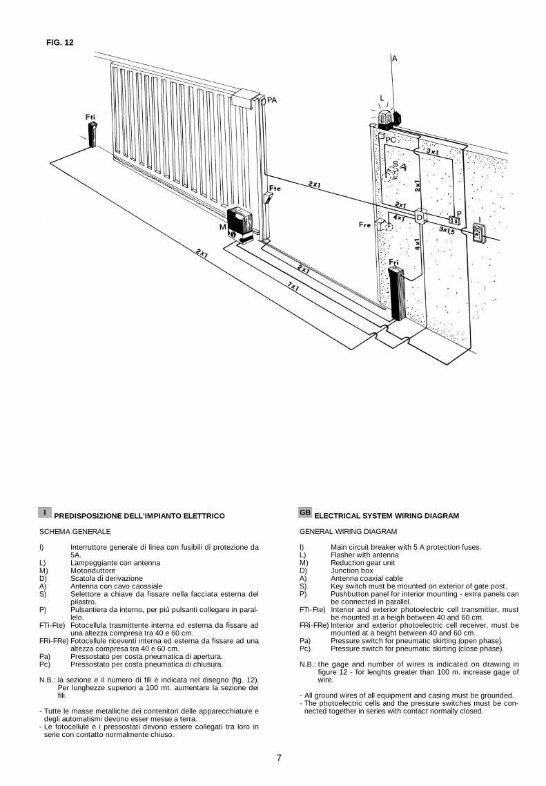
REGOLAZIONE DELLA FRIZIONE DI SICUREZZACaricamento della frizione:Tenendo fermo l’albero motore con l’apposita chiave in dotazione(CH 17), avvitare il dado posto sopra la molla di caricamento (CH13).Allentamento della frizione:Eseguire la stessa operazione girando però il dado (CH 13) insenso antiorario.È consigliabile che la forza di spinta regolata non sia troppo bassa,affinché un qualsiasi deposito di materiale sulla rotaia di scorri-mento non provochi l’arresto del cancello. Tuttavia bisogna fareattenzione a mantenersi nei limiti di sicurezza antischiacciamentoprevisti dalle normative.
ADJUSTMENT OF THE SAFETY CLUTCHLoading of clutch:Keep the motor shaft still with the special spanner on equipment(CH 17), and tighten the nut located on top of the loading spring(CH 13).Release of the clutch:Carry out the same operation as above but turn the nut (CH 13)counterclokwise.Make sure the operating force is not too low, so as to avoid use-less stops of the gate due to deposits on the rail. However it isimportant to observe the anti-squash safety limits regulations.
REGLAGE DE L’EMBRAYAGE DE SECURITERechargement de l’embrayage:Tenir arrête l’arbre moteur avec la clef (CH 17) en dotation et serrerl’écrou placé sur le ressort de rechargement (CH 13).Desserrement de l’embrayage:Effectuer la même opération en tournant l’écrou (CH 13) dans lesens contraire à celui des aiguilles d‘une montre.La force de poussée ne doit pas être réglée trop basse puisquedans ce cas un dépot même minime de matériel sur le rail de glis-sement provoquerait l’arrêt du portail. Il faut toutefois rester dansles limites de sécurité antiécrasement prévues par les normes.
EINSTELLUNG DER SICHERHEITSKUPPLUNGDie Antriebswelle wird mit dem mitgelieferten Gabelschlüssel 17festgehalten und die Mutter mit den mitgelieferten Gabelschlüssel13 gedreht. Drehen Sie im Uhrzeigersinn erhöht sich die Kraft,drehen Sie gegen den Uhrzeigersinn, vermindert sich die Kraft desAntriebs. Es ist ratsam die Schubkraft nicht zu gering einzustellenda Schmutz auf der Laufschiene des Tores den Antrieb dannschon anhält.Bei niedrigen Temperaturen kann es nötig sein, die Kraft etwas zuerhöhen, da dann die Tore schwerer laufen.Bitte beachten Sie die gesetzl ich vorgeschriebenenSicherheitsrichtlinien.
REGULACION DEL EMBRAGUE DE SEGURIDADCarga del embrague:Tener inmovíl el eje del motor y con la respectiva llave en dotación(CH 17) atornillar el dado puesto sobre el resorte de carga (CH 13).Regulación del embrague:Efectuar la misma operación pero girando el dado (CH 13) en elsentido anti-horario.La fuerza de impulso no bede ser regulada demasiado baja, demodo que si se deposita material sobre el riel de desplazamiento,no se determina la parada del portón. También es necesario man-tenerse en los limites de seguridad anti-aplaste previsto por lasnormas.
I
GB
F
D
E
FIG. 13
10
13
17
-
+

MANOVRA DI EMERGENZAPer effettuare la manovra manuale del cancello nei casi di emer-genza, inserire la chiave personalizzata nella serratura (fig. 14),ruotare la chiave nel verso indicato dalla freccia. Impugnare lamanopola e ruotarla nel senso della freccia come indicato in (fig.15). In tal modo si rende folle il pignone rendendo libero il movi-mento del cancello. La chiave non si può togliere dalla serraturafino a quando la manopola non viene riportata nella posizione ini-ziale (azionamento motorizzato).
EMERGENCY MANOEUVRETo operate the gate manually, in case of emergency, put thepersonalized key into the lock (Fig. 14) and turn the key in thedirection indicated by the arrow. Take hold of the knob and turn itin the direction of the arrow, as indicated in (Fig. 15). In so doingthe pinion becomes idle and the gate movement is freed. The keycannot be removed from the lock until the knob is returned to itsoriginal position (motor-driven control).
MANOEUVRE D’URGENCEPour effectuer la manoeuvre manuelle du portail dans les casd’urgence, insérer la clé personnalisée dans la serrure (fig. 14),tourner la clé dans le sens indiqué par la flèche et tourner la poi-gnée dans le sens de la flèche comme indiqué dans la fig. 15. Decette façon on rend le pignon libre en dégageant le mouvement duportail. Il n’est pas possible d’enlever la clé de la serrure tantqu’on ne reporte la poignée dans la position initiale (actionnementmotorisé).
NOTENTRIEGELUNGDer Antrieb ist mit einer einfach zu bedienenden Notentriegelungausgestattet. Dadurch haben Sie die Möglichkeit, das Tor z.B. beiStromausfall, von Hand zu öffnen. Wie in Abb. 14 gezeigt, steckenSie den mitgelieferten Schlüssel in das Schloß und entriegeln ent-sprechend den Pfeilen. Nun kann das Tor von Hand geschobenwerden. Der Schlüssel kann erst abgezogen werden, wenn dasAntriebszahnrad wieder verriegelt ist. Abb. 15.
MANIOBRA DE EMERGENCIAPara maniobrar manualmente la verja en los casos de emergencia,introducir la llave personalizada en la cerradura (fig. 14), girarla enel sentido indicado por la flecha; empuñar el pomo y girarlo en elsentido de la flecha como se indica en la (fig.. 15). De esta manerase suelta el piñón, liberando el movimiento de la verja. La llave nose puede quitar de la cerradura hasta que no se haya colocado elpomo en la posición inicial (accionamiento motorizado).
I
GB
F
D
E
FIG. 14 FIG. 15
11