Embed Size (px)
Citation preview
120 Braley Rd. P.O. Box 429 East Freetown, MA 02717-0429 www.htproducts.com
Pioneer
INSTALLATION
START-UP
MAINTENANCE
PARTS
Pioneer Water Heater Models* PHR100-55 / 130-55 / 160-55 / 199-55
*A suffix of “LP” denotes propane gas
NOTICE: HTP reserves the right to make product changes or updates without notice and will not be held liable for typographical errors in literature.
This manual must be used by a qualified installer/service technician. Read all instructions in this manual before installing. Perform steps in the given order. Failure to comply could result in substantial property damage, severe personal injury, or death.

2
IF THE INFORMATION IN THIS MANUAL IS NOT FOLLOWED EXACTLY, A FIRE OR EXPLOSION MAY RESULT, CAUSING PROPERTY DAMAGE, PERSONAL INJURY, OR LOSS OF LIFE. DO NOT STORE GASOLINE OR OTHER FLAMMABLE VAPORS AND LIQUIDS IN THE VICINITY OF THIS OR ANY OTHER APPLIANCE.
WHAT TO DO IF YOU SMELL GAS • Do not try to light any appliance. • Do not touch any electrical switch. • Do not use any phone in your building. • Immediately call your gas supplier from a neighbor’s phone. Follow the gas supplier’s
instructions. • If you cannot reach your gas supplier, call the fire department. Installation and service must be
provided by a qualified installer, service agency, or the gas supplier.

3
The following defined terms are used throughout this manual to bring attention to the presence of hazards of various risk levels or to important product information.
DANGER indicates an imminently hazardous situation which, if not avoided, will result in death or serious injury.
WARNING indicates a potentially hazardous situation which, if not avoided, could result in death or serious injury.
CAUTION indicates a potentially hazardous situation which, if not avoided, may result in minor or moderate injury.
CAUTION used without the safety alert symbol indicates a potentially hazardous situation which, if not avoided, may result in property damage.
FOREWORD This manual is intended to be used in conjunction with other literature provided with the heater. This includes all related control information. It is important that this manual, all other documents included with this system, and additional publications including the National Fuel Gas Code, ANSI Z223.1-2002, be reviewed in their entirety before beginning any work. Installation should be made in accordance with the regulations of the local code authorities and utility companies which pertain to this type of heating equipment. NOTE TO CONSUMER: PLEASE KEEP ALL INSTRUCTIONS FOR FUTURE REFERENCE.

4
FOR THE INSTALLER
This appliance must be installed by qualified and licensed personnel. The installer should be guided by the instructions furnished with the heater, and with local codes and utility company requirements. In the absence of local codes, preference should be given to the National Fuel Gas Code, ANSI Z223.1-2002. INSTALLATIONS MUST COMPLY WITH: Local, state, provincial, and national codes, laws, regulations and ordinances. The latest version of the National Fuel Gas Code
, ANSI Z223.1, from American Gas Association Laboratories, 8501 East Pleasant Valley Road, Cleveland, OH 44131.
In Canada – CGA No. B149 (latest version), from Canadian Gas Association Laboratories, 55 Scarsdale Road, Don Mills, Ontario, Canada M3B 2R3. Also, Canadian Electrical Code C 22.1, from Canadian Standards Association, 5060 Spectrum Way, Suite 100, Mississauga, Ontario, Canada L4W 5N6. Code for the installation of Heat Producing Appliances (latest version), from American Insurance Association, 85 John Street, New York, NY 11038. The latest version of the National Electrical Code
, NFPA No. 70.
This product is for installation in closed loop systems ONLY! Use of this product in any manner other than described in this manual may result in premature product failure, substantial property damage, severe personal injury, or death. Damage or failure of this product (or the system in which it is installed) due to unauthorized use IS NOT COVERED BY WARRANTY.
This manual must only be used by a qualified heating installer/service technician. Read all instructions in this manual before installing. Perform steps in the order given. Failure to comply could result in severe personal injury, death or substantial property damage.

5
TABLE OF CONTENTS PART 1 – GENERAL SAFETY INFORMATION .......................................................................................... 7
A. PRECAUTIONS .................................................................................................................................... 7
B. IMPROPER COMBUSTION ................................................................................................................. 8
C. GAS ...................................................................................................................................................... 8
D. WHEN SERVICING THE HEATER ...................................................................................................... 8
E. WATER QUALITY ................................................................................................................................ 8
F. WINTERIZING ...................................................................................................................................... 9
PART 2 – BEFORE YOU START ................................................................................................................ 9
A. WHAT’S IN THE BOX ........................................................................................................................... 9
B. HOW THE HEATER OPERATES ........................................................................................................ 9
C. OPTIONAL EQUIPMENT ................................................................................................................... 11
PART 3 – DIMENSIONS AND CLEARANCES .......................................................................................... 12
PART 4 – PREPARE HEATER LOCATION .............................................................................................. 13
A. BEFORE LOCATING THE HEATER .................................................................................................. 13
B. LEVELING .......................................................................................................................................... 14
C. CLEARANCES FOR SERVICE ACCESS .......................................................................................... 14
D. RESIDENTIAL GARAGE INSTALLATION ......................................................................................... 14
E. EXHAUST VENT AND INTAKE AIR VENT ........................................................................................ 14
1. DIRECT VENT INSTALLATION OF EXHAUST AND INTAKE ....................................................... 15
2. INDOOR COMBUSTION AIR INSTALLATION IN CONFINED OR UNCONFINED SPACE ......... 15
F. PREVENT COMBUSTION AIR CONTAMINATION ........................................................................... 16
G. REMOVING A HEATER FROM A COMMON VENT SYSTEM ......................................................... 16
PART 5 – PREPARE THE HEATER .......................................................................................................... 17
PART 6 – HEATER PIPING ....................................................................................................................... 18
A. GENERAL PIPING INFORMATION ................................................................................................... 18
B. RELIEF VALVE ................................................................................................................................... 18
C. BACKFLOW PREVENTER ................................................................................................................ 19
D. SYSTEM WATER PIPING METHODS .............................................................................................. 19
E. CIRCULATOR PUMPS ....................................................................................................................... 19
F. INDIRECT FIRED WATER HEATER SCALDING .............................................................................. 20
G. HYDRONIC PIPING - CIRCULATORS, ZONE VALVES AND MULTIPLE HEATERS ..................... 20
H. FILL AND PURGE HEATING SYSTEM ............................................................................................. 21
I. ZONING WITH ZONE VALVES ........................................................................................................... 22
J. ZONING WITH CIRCULATORS ......................................................................................................... 22

6
K. MULTIPLE HEATERS ........................................................................................................................ 22
L. PIPING DETAIL .................................................................................................................................. 23
PART 7 – VENTING, COMBUSTION AIR AND CONDENSATE REMOVAL ........................................... 26
A. GENERAL ........................................................................................................................................... 26
B. APPROVED MATERIALS FOR EXHAUST AND INTAKE AIR VENTS ............................................. 26
C. EXHAUST AND INTAKE AIR VENT PIPE LOCATION ..................................................................... 27
1. DETERMINE EXHAUST VENT LOCATION ................................................................................... 27
2. DETERMINE AIR INTAKE VENT LOCATION ................................................................................ 27
D. EXHAUST AND INTAKE AIR VENT SIZING ..................................................................................... 28
E. LONGER VENT RUNS ....................................................................................................................... 29
F. EXHAUST VENT AND INTAKE AIR PIPE INSTALLATION ............................................................... 30
G. VENTING DRAWINGS ....................................................................................................................... 31
1. DIRECT VENT INSTALLATION OF EXHAUST AND INTAKE ....................................................... 31
2. INDOOR COMBUSTION AIR INSTALLATION IN CONFINED OR UNCONFINED SPACE ......... 37
H. EXHAUST VENT AND INTAKE AIR PIPE INSTALLATION .............................................................. 39
I. REMOVING AN EXISTING WATER HEATER .................................................................................... 39
J. CONDENSATE REMOVAL SYSTEM ................................................................................................. 40
PART 8 – FIELD WIRING ........................................................................................................................... 41
A. INSTALLATION MUST COMPLY WITH: ........................................................................................... 41
B. FIELD WIRING ................................................................................................................................... 41
C. LINE VOLTAGE WIRING FOR STANDARD HEATER ...................................................................... 42
D. THERMOSTAT ................................................................................................................................... 42
E. OUTDOOR SENSOR (OPTIONAL) ................................................................................................... 43
F. INDIRECT SENSOR (OPTIONAL) ..................................................................................................... 43
G. 0-10 VOLT BUILDING CONTROL SIGNAL (OPTIONAL) ................................................................. 43
H. UL353 LOW WATER CUT-OFF INTERFACE KIT (OPTIONAL ........................................................ 44
I. WIRING OF CASCADE SYSTEM COMMUNICATION BUS ............................................................... 44
J. CASCADE MASTER PUMP AND SENSOR WIRING ........................................................................ 45
K. CASCADE FOLLOWER PUMP AND SENSOR WIRING .................................................................. 46
PART 9 – START-UP PREPARATION ...................................................................................................... 46
A. CHECK/CONTROL WATER CHEMISTRY ........................................................................................ 47
B. FREEZE PROTECTION (WHEN USED) ........................................................................................... 47
C. FILL AND TEST WATER SYSTEM .................................................................................................... 48
D. PURGE AIR FROM WATER SYSTEM .............................................................................................. 48
E. CHECK THERMOSTAT CIRCUIT(S) ................................................................................................. 48

7
F. FINAL CHECKS BEFORE STARTING HEATER ............................................................................... 49
PART 10 – START-UP PROCEDURE ....................................................................................................... 49
A. OPERATING INSTRUCTIONS .......................................................................................................... 49
B. CASCADE SYSTEM ........................................................................................................................... 50
C. ADJUSTING THE SET POINT ........................................................................................................... 50
D. STATUS MENU .................................................................................................................................. 51
E. TEST MODE ....................................................................................................................................... 52
F. PURGE AIR FROM WATER SYSTEM ............................................................................................... 53
PART 11 – PROGRAMMING THE HEATER ............................................................................................. 53
A. PROGRAM ACCESS ......................................................................................................................... 53
B. PROGRAM SYSTEM SETTINGS ...................................................................................................... 53
PART 12 – TROUBLESHOOTING ............................................................................................................. 56
A. HEATER ERROR CODE .................................................................................................................... 56
B. HEATER ERROR ............................................................................................................................... 56
C. HEATER FAULT ................................................................................................................................. 56
PART 13: MAINTENANCE ......................................................................................................................... 61
MAINTENANCE NOTES ............................................................................................................................ 64
HTP CUSTOMER INSTALLATION RECORD FORM........................................................................ 65
PART 1 – GENERAL SAFETY INFORMATION
A. PRECAUTIONS This appliance is for indoor installations only. Clearance to combustible materials: 0” top, bottom, sides and back. Front must have room for service, 24” recommended. (A combustible door or removable panel is acceptable front clearance.) This appliance has been approved for closet installation. Do not install this appliance directly on carpeting. For installation on combustible flooring. Category IV vent systems only.
INSTALLER – Read all instructions in this manual before installing. Perform steps in the order given. USER – This manual is for use only by a qualified heating installer/service technician. Refer to user’s information manual for your reference. Have this heater serviced/inspected by a qualified service technician annually. FAILURE TO ADHERE TO THE GUIDELINES ON THIS PAGE CAN RESULT IN SUBSTANTIAL PROPERTY DAMAGE, SEVERE PERSONAL INJURY, OR DEATH.

8
NOTE: If the heater is exposed to the following, do not operate until all corrective steps have been made by a qualified serviceman: 1. FIRE 2. DAMAGE 3. WATER Any claims for damage or shortage in shipment must be filed immediately against the transportation company by the consignee. DO NOT USE THIS APPLIANCE IF ANY PART HAS BEEN UNDERWATER. Immediately call a qualified service technician. Replace any part of the control unit that has been under water.
Be sure to disconnect electrical power before opening heater cabinet. Failure to do so could result in an electrical shock that could result in serious injury or death.
B. IMPROPER COMBUSTION
NOTE: Do not obstruct the flow of combustion and ventilating air. Adequate air must be provided for safe operation.
C. GAS Should overheating or gas supply fail to shut off, do not turn off or disconnect electrical supply to circulator. Instead, shut off the gas supply at a location external to the appliance.
D. WHEN SERVICING THE HEATER • To avoid electric shock, disconnect electrical supply before performing maintenance. • To avoid severe burns, allow heater to cool.
E. WATER QUALITY • Do not use petroleum-based cleaning or sealing compounds in a heater system. Gaskets and
seals in the system may be damaged. This can result in substantial property damage. • Do not use “homemade cures” or “heater patent medicines”. Substantial property damage,
damage to heater, and/or serious personal injury may result. • Continual fresh make-up water will reduce heater life. Mineral buildup reduces heat transfer,
overheats the heat exchanger, and causes failure. Addition of oxygen by make-up water can cause internal corrosion in system components. Leaks in the heater or piping must be repaired at once.
• If you have an old system with cast iron radiators, thoroughly flush the system (without heater connected) to remove sediment. Sediment can reduce the efficiency of the heater and, in extreme cases, cause damage to the internal heat exchanger.
NEVER use any toxic chemical, including automotive, standard glycol antifreeze, or ethylene glycol made for hydronic (non-potable) systems. These chemicals can attack gaskets and seals in water systems, are poisonous if consumed, and can cause injury or death.

9
F. WINTERIZING NOTE: Consider piping and installation when determining heater location. Do not place the heater in an area where it will be prone to freezing. To winterize the heater, drain the entire system. Pump two gallons of non-toxic, NSF food grade, FDA rated GRAS (Generally Recognized As Safe) propylene glycol into the tank. Consult the glycol manufacturer for specific instructions on concentration percentage as well as freeze and burst protection methods. Check the concentration of antifreeze to assure protection is adequate to protect the bottom of the heater from freezing.
PART 2 – BEFORE YOU START
A. WHAT’S IN THE BOX Also included with the heater:
• Pressure and Temperature Gauge • 30 psi Temperature and Pressure Relief Valve • Intake PVC Tee with Screens • Exhaust PVC Coupling with Screens • Installation Manual • Warranty • Outdoor Sensor (Part # 7250P-319)
B. HOW THE HEATER OPERATES Condensing Technology maximizes efficiency by measuring the needs of your heating system through the use of sensors and a control unit. The heater uses data gathered by these sensors to intelligently deliver highly efficient hydronic heating. Heat Exchanger The highly efficient combustion heat exchanger flows exhaust gas through the primary section into the secondary heat exchanger section, where the coldest water on the bottom of the tank extracts the last residual amount of energy. Modulating Combustion System Modulation during central heating operation is based on the supply temperature. The set point used for the control depends upon the programmed central heating curve. The slope of the heating curve can be changed by the heater installer. The control monitors the system, regulating burner output during operation to match system demand, effectively increasing efficiency and providing substantial fuel savings. Gas Valve The gas valve senses suction from the blower, allowing gas to flow only if combustion air is flowing. Swirl Plate System The Swirl Plate on the gas valve controls air and gas flow into the burner, assuring better mixing for improved combustion. Combination Top High Temperature Sensor This sensor monitors supply temperature. The control module adjusts heater firing rate, correcting supply temperature.

10
Bottom Water Temperature Sensor This sensor monitors return water temperature. The control module reduces or increases heater input accordingly. Temperature and Pressure Gauge Allows the user to monitor system temperature and pressure. Control The integrated control system monitors return and supply water temperature. The control system regulates the unit’s BTU output by controlling fan speed, allowing the unit to deliver only the amount of heated energy required. Burner Constructed with metal fiber and stainless steel, the burner uses pre-mixed air and gas, providing a wide range of firing rates. Electrical Field Connections with Terminal Strips The cabinet allows easy access to the line voltage and low voltage terminal strips, which are clearly marked to facilitate wiring to the heater. Condensate Drain Connection This is a condensing high efficiency appliance, and therefore has a condensate removal system. Condensate is nothing more than water vapor derived from combustion products. The condensate is similar to that of an automobile when it is initially started. It is very important that the condensate line slopes away from the heater, down to a suitable drain. If the condensate outlet is lower than the drain, you must use a condensate removal pump (kit 554200, available from HTP). A condensate filter, if required by local authorities, can be made up of lime crystals, marble or phosphate chips, and will neutralize the condensate. This can be purchased from HTP (7450P-212) and installed in the field. It is also very important that the condensate line is not exposed to freezing temperatures or any other type of blockage. Plastic pipe must be the only material used for condensate line. Steel, brass, copper, or other materials will be subject to corrosion or deterioration. A second vent may be necessary to prevent a condensate line vacuum lock in a long, horizontal line. Also, an increase in pipe size may be necessary to drain properly. Support of the condensation line may be needed to avoid blockage of flow. Spark Ignition The burner flame ignites by applying high voltage to the system spark electrode. This causes a spark from electrode to ground. Outdoor Sensor The outdoor sensor allows the installer to make the heater even more efficient by basing temperature delivered to the central heating circuits on outdoor temperature. (See Optional Equipment, Section C). (Optional) Indirect Tank Sensor – Indirect Priority
To control the temperature of low temperature heating circuits when using an indirect fired water heater, a thermostatic mixing valve is required. Failure to install a thermostatic mixing valve could result in property damage.

11
The indirect sensor allows the installer to operate the heater with two temperatures: one for central heating and the other for the SuperStor Indirect Water Heater. This allows the user to increase water temperature supplied to the indirect to get faster recovery by prioritizing flow at a higher rate than may be needed for central heating. NOTE: This application requires two separate circulators. (See Optional Equipment, Section C).
C. OPTIONAL EQUIPMENT Below is a list of optional equipment available from HTP:
• System Sensor (Part # 7250P-324) • Indirect Tank Sensor (Part # 7250P-325) • 3” Stainless Steel Outside Termination Vent Kit (V1000) • 4” Stainless Steel Outside Termination Vent Kit (V2000) • 2” PVC Concentric Vent Kit (Part # KGAVT0501CVT) • 3" PVC Concentric Vent Kit (Part # KGAVT0601CVT) • U.L. 353 Compliant Low Water Cut-Off Interface Kit with Manual Reset (Part # 7450P-225) • Alarm System (Part # 7350P-602) (to monitor any failure) • PC Connection Kit (Part # 7250P-320) • Condensate Neutralizer (Part # 7450P-212) • Vision 2 Temperature Mixing Control (Part # 7250P-322)
These additional options may be purchased through your HTP distributor.

12
PART 3 – DIMENSIONS AND CLEARANCES
Figure 1 – LP-325-L

13
CLEARANCE ACCESS
PART 4 – PREPARE HEATER LOCATION Before considering location, there are many factors to be addressed. These factors are covered in detail in this installation manual. Please read the entire manual, as it could save time and money. Piping, Venting, and Condensation Removal are just a few of the issues that need attention prior to the installation of the heater.
A. BEFORE LOCATING THE HEATER Check for nearby connections to:
• System water piping • Venting connections • Gas supply piping • Electrical power • Condensate drain
Check area around heater. Remove any combustible materials, gasoline, and other flammable liquids.
Failure to keep heater area clear and free of combustible materials, liquids, and vapors can result in substantial property damage, severe personal injury, or death. The heater gas control system components must be protected from dripping water during operation and service.
Figure 2 – LP-325-M

14
If replacing an existing heater, check for and correct any existing system problems, such as: • System leaks • Heater is located in a condition that could cause the system to freeze and leak. • Incorrectly-sized expansion tank
Clean and flush system when reinstalling a heater.
B. LEVELING
In order for the condensate to properly flow out of the collection system, the area where you locate the heater must be level. Location must also fully support the weight of the heater when filled with water (650 lbs).
C. CLEARANCES FOR SERVICE ACCESS See Part 3 for recommended service clearances. If you do not provide the minimum clearances shown, it may not be possible to service the heater without removing it from the space.
The space must be provided with combustion/ventilation air openings correctly sized for all other appliances located in the same space as the heater. The heater cover must be securely fastened to prevent the heater from drawing air form the heater room. This is particularly important if the heater is in a room with other appliances. Failure to comply with the above warnings could result in substantial property damage, severe personal injury, or death.
D. RESIDENTIAL GARAGE INSTALLATION If the heater is located in a residential garage, per ANSI Z223.1:
• Mount the bottom of the heater a minimum of 18” above the floor of the garage, to ensure the burner and ignition devices are well off the floor.
• Locate or protect the heater so it cannot be damaged by a moving vehicle.
E. EXHAUST VENT AND INTAKE AIR VENT The heater is rated ANSI Z21.10.3 Category IV (pressurized vent, likely to form condensate in the vent) and requires a special vent system designed for pressurized venting. NOTE: The venting options described here (and further detailed in Venting, Part 8 in this manual) are the lone venting options approved for this water heater. Failure to vent the water heater in accordance with the provided venting instructions will void the warranty.
Failure to vent the water heater properly will result in serious personal injury or death.
Vents must be properly supported. Heater intake and exhaust connections are not designed to carry heavy weight. Vent support brackets must be within 1’ of the heater and the balance at 4’ intervals. Heater must be readily accessible for visual inspection for the first 3’ from the heater.

15
1. DIRECT VENT INSTALLATION OF EXHAUST AND INTAKE If installing a direct vent option, combustion air must be drawn from the outdoors directly into the appliance intake, and exhaust must terminate outside. There are three basic direct vent options detailed in this manual: 1. Side Wall Venting, 2. Roof Venting, and 3. Unbalanced Venting. Be sure to locate the heater such that the air intake and exhaust vent piping can be routed through the building and properly terminated. Different vent terminals can be used to simplify and eliminate multiple penetrations in the building structure (see Optional Equipment in Venting Section). The air intake and exhaust vent piping lengths, routing and termination methods must all comply with the methods and limits given in the Venting section, Part 8 of this manual. When installing a combustion air intake from outdoors, care must be taken to utilize uncontaminated combustion air. NOTE: To prevent combustion air contamination, see Table 1.
2. INDOOR COMBUSTION AIR INSTALLATION IN CONFINED OR UNCONFINED SPACE This heater requires fresh, uncontaminated air for safe operation and must be installed in a mechanical room where there is adequate combustion and ventilating air. NOTE: To prevent combustion air contamination, see Table 1. Combustion air from the indoor space can be used if the space has adequate area or when air is provided through a duct or louver to supply sufficient combustion air based on the appliance input. Never obstruct the supply of combustion air to the appliance. If the appliance is installed in areas where indoor air is contaminated (see Table 1) it is imperative that the appliance be installed as direct vent so that all combustion air is taken directly from the outdoors into the appliance intake connection. Unconfined space is space with volume greater than 50 cubic feet per 1,000 Btu/hour (4.8 cubic meters per kW) of the total input rating of all fuel-burning appliances installed in that space. Rooms connected directly to this space, through openings not furnished with doors, are considered part of the space. See Figure 16 on page 38 for installation diagram. Confined space is space with volume less than 50 cubic feet per 1,000 Btu/hour (4.8 cubic meters per kW) of the total input rating of all fuel-burning appliances installed in that space. Rooms connected directly to this space, through openings not furnished with doors, are considered part of the space. When drawing combustion air from inside a conventionally constructed building to a confined space, such space should be provided with two permanent openings: one located 6” (15 cm) below the space ceiling, the other 6” (15cm) above the space floor. Each opening should have a free area of one square inch per 1,000 Btu/hr (22cm2/kW) of the total input of all appliances in the space, but not less than 100 square inches (645cm2). If the confined space is within a building of tight construction, air for combustion must be obtained from the outdoors as outlined in the Venting Section, Part 8 of this manual.
When drawing combustion air from the outside into the mechanical room, care must be taken to provide adequate freeze protection.
Do not attempt to vent this appliance by any means other than those described in this manual. Doing so will void the warranty, and may result in severe personal injury or death.

16
Failure to provide an adequate supply of fresh combustion air can cause poisonous flue gases to enter living space, which could result in severe personal injury or death. NOTE: To prevent combustion air contamination, see Table 1.
F. PREVENT COMBUSTION AIR CONTAMINATION Install intake air piping for the heater as described in the Venting Section. Do not terminate exhaust in locations that can allow contamination of intake air.
Ensure that the intake air will not contain any of the contaminants listed in Table 1. Contaminated air will damage the heater, resulting in possible substantial property damage, severe personal injury, or death. For example, do not pipe intake air vent near a swimming pool. Also, avoid areas subject to exhaust fumes from laundry facilities. These areas always contain contaminants.
PRODUCTS TO AVOID AREAS LIKELY TO HAVE CONTAMINANTS Spray cans containing fluorocarbons Dry cleaning/laundry areas and establishments Permanent wave solutions Swimming pools Chlorinated waxes/cleaners Metal fabrication plants Chlorine-based swimming pool chemicals Beauty shops Calcium chloride used for thawing Refrigeration repair shops Sodium chloride used for water softening Photo processing plants Refrigerant leaks Auto body shops Paint or varnish removers Plastic manufacturing plants Hydrochloric or Muriatic acid Furniture refinishing areas and establishments Cements and glues New building construction Antistatic fabric softeners used in clothes dryers Remodeling areas Chlorine-type bleaches, laundry detergents, and cleaning solvents
Garages and workshops
Adhesives used to fasten building products Table 1 – Contaminant Table
G. REMOVING A HEATER FROM A COMMON VENT SYSTEM
Do not install the heater into a common vent with any other appliance. This will cause flue gas spillage or appliance malfunction, resulting in possible substantial property damage, severe personal injury, or death.
Failure to follow all instructions can result in flue gas spillage and carbon monoxide emissions, causing severe personal injury or death.
NOTE: DAMAGE TO THE HEATER CAUSED BY EXPOSURE TO CORROSIVE VAPORS IS NOT COVERED BY WARRANTY. (Refer to the limited warranty for complete terms and conditions).

17
When removing an existing heater, follow the steps below. 1. Seal any unused openings in the common venting system. 2. Visually inspect the venting system for proper size and horizontal pitch to determine if there is blockage, leakage, corrosion or other deficiencies that could cause an unsafe condition. 3. If practical, close all building doors, windows and doors between the space in which the appliance remains connected to the common venting system and other spaces in the building. Turn on clothes dryers and any appliances not connected to the common venting system. Turn on any exhaust fans, such as range hoods and bathroom exhausts, at maximum speed. Do not operate a summer exhaust fan. Close all fireplace dampers.
4. Place in operation the appliance being inspected. Follow the lighting instructions. Adjust the thermostat so the appliance will operate continuously. 5. Test for spillage at the draft hood relief opening after 5 minutes of main burner operation. Use the flame of a match or candle or smoke from a cigarette. 6. After it has been determined that each appliance remaining connected to common venting system properly vents when tested as outlined, return doors, windows, exhaust fans, fireplace dampers and any other gas burning appliance to their previous condition of use. 7. Any improper operation of the common venting system should be corrected to conform to the National Fuel Gas Code, ANSI Z223.1. When resizing any portion of the common venting system, the system should approach the minimum size as determined using the appropriate tables in Appendix G in the National Fuel Gas Code, ANSI Z 223.1.
PART 5 – PREPARE THE HEATER
UNCRATING HEATER – Any claims for damage or shortage in shipment must be filed immediately against the transportation company by the consignee.
COLD WEATHER HANDLING – If the heater has been stored in a very cold location (BELOW 0oF) before installation, handle with care until the plastic components come to room temperature. Remove all sides of the shipping crate to allow the heater to be lifted into its installation location.
Figure 4 - CO Warning Label
Figure 3

18
PART 6 – HEATER PIPING Plumbing of this heater should only be done by a qualified, licensed plumber in accordance with all local plumbing codes. The heater may be connected to an indirect storage tank to supply domestic hot water. HTP offers 30/45/60/80/119 gallon size indirect storage tanks in Stainless Steel or 50/80/119 in Glass Lined construction. These indirect storage tanks will be directly connected to the supply and return connection.
A. GENERAL PIPING INFORMATION
Use two wrenches when tightening water piping at heater. Use one wrench to prevent the heater return or supply line from turning. Failure to prevent piping connections from turning could cause damage to heater components.
The heater control module uses temperature sensors to provide both high limit protection and modulating temperature control. The control module also provides low water protection by sensing the water level in the heater. Some codes/jurisdictions may require additional external controls.
B. RELIEF VALVE Install supplied pressure and temperature relief valve. Connect discharge piping to a safe disposal location, following the guidelines below. Replacement is available. See parts list.
To avoid water damage or scalding due to relief valve operation:
• Discharge line must be connected to relief valve outlet and run to a safe place of disposal. Terminate the discharge line in a manner that will prevent possibility of severe burns or property damage should the relief valve discharge.
• Discharge line must be as short as possible and the same size as the valve discharge connection throughout its entire length.
• Discharge line must pitch downward from the valve and terminate at least 6” above the floor drain, making discharge clearly visible.
• The discharge line shall terminate plain, not threaded, with a material serviceable for temperatures of 375oF or greater.
• Do not pipe discharge to any location where freezing could occur. • No shutoff valve may be installed between the relief valve and heater or in the discharge line. Do
not plug or place any obstruction in the discharge line. • Test the operation of the relief valve after filling and pressurizing the system by lifting the lever.
Make sure the valve discharges freely. If the valve fails to operate correctly, replace with a new properly rated relief valve.
FAILURE TO COMPLY WITH THE ABOVE GUIDELINES COULD RESULT IN FAILURE OF RELIEF VALVE OPERATION, RESULTING IN POSSIBILITY OF SUBSTANTIAL PROPERTY DAMAGE, SEVERE PERSONAL INJURY, OR DEATH.
Never use dielectric unions for galvanized steel fittings when connecting to a stainless steel storage tank or heater.

19
C. BACKFLOW PREVENTER Use a backflow preventer specifically designed for hydronic heater installations. This valve should be installed on the cold water fill supply line per local codes (see Piping Details).
D. SYSTEM WATER PIPING METHODS EXPANSION TANK AND MAKE-UP WATER 1. Ensure that the expansion tank is sized to correctly handle heater and system water volume and temperature. The heater volume is 55 gallons.
Undersized expansion tanks cause system water to be lost from the relief valve, causing make-up water to be added. Eventual heater failure can result due to excessive make-up water addition. SUCH FAILURE IS NOT COVERED BY WARRANTY. 2. The expansion tank must be located as shown in the Heater Piping Details, or following recognized design methods. See expansion tank manufacturer’s instructions for details. 3. Connect the expansion tank on the suction side of the circulator. Always install the system fill connection at the same point as the expansion tank connection to the system. 4. Most chilled water systems are piped using a closed type expansion tank.
E. CIRCULATOR PUMPS
DO NOT install automatic air vents on closed type expansion tank systems. Air must remain in the system and return to the tank to provide an air cushion. An automatic air vent would cause air to leave the system, resulting in improper operation of the expansion tank. SIZING SPACE HEAT SYSTEM PIPING 1. See piping details in this manual. Special attention must be paid when connecting an indirect storage tank, as temperature delivered to low temperature circuits may be higher than desired. The use of thermostatic mixing valves is required to protect these circuits.
To control the temperature of low temperature heating circuits when using an indirect fired water heater, a thermostatic mixing valve is required. Failure to install a thermostatic mixing valve when using an indirect fired water heater could result in serious personal injury or death due to scalds. 2. Size the piping and components in the space heating system using recognized design methods.

20
F. INDIRECT FIRED WATER HEATER SCALDING This heater can deliver scalding water. Be careful whenever using hot water to avoid scalding injury. Certain appliances, such as dishwashers and automatic clothes washers may require increased water temperature. By setting the thermostat on this heater to obtain the increased water temperature required by these appliances, you may create the potential for scald injury. To protect against injury, you should install a mixing valve in the water system. This valve will reduce point of discharge temperature by mixing cold and hot water in branch supply lines. Such valves are available from your local plumbing supplier.
Table 2 details the relationship of water temperature and time with regard to scald injury and may be used as a guide in determining the safest water temperature for your applications.
G. HYDRONIC PIPING - CIRCULATORS, ZONE VALVES AND MULTIPLE HEATERS This heater is designed to function in a closed loop 15 PSI System. A factory installed low water cut off will ensure that you have adequate water in the system. We have also included a T&P gauge which allows the user to monitor system pressure and outlet temperature from the heater. Install the heater so the gas ignition system components are protected from water (dripping, spraying, etc.) allowing clearance for basic service of circulator replacement, valves and other parts. Observe minimum 1” clearance around all hot water pipes not protected by non-combustible materials. On a heater installed above radiation level, some states and local codes require a low water cut off device at the time of installation. If the heater supplies hot water to heating coils in air handler units, flow control valves or other devices must be installed to prevent gravity circulation of heater water in the coils during the cooling cycle. Chilled water medium must be piped in parallel with the heater. Basic steps are listed below which will guide you through the installation of the heater. 1. Connect the system return marked “Return”. 2. Connect the system supply marked “Supply”. 3. Install purge and balance valve or shut off valve and drain on system return to purge air out of each zone. 4. Install a back flow preventer on the cold feed make-up water line.
APPROXIMATE TIME / TEMPERATURE RELATIONSHIPS IN SCALDS
120oF More than 5 minutes 125oF 1 ½ to 2 minutes 130oF About 30 seconds 135oF About 10 seconds 140oF Less than 5 seconds 145oF Less than 3 seconds 150oF About 1 ½ seconds 155oF About 1 second
Table 2

21
5. Install a pressure reducing valve on the cold feed make-up water line, (15 PSI nominal on the system return). Check temperature and pressure gauge which should read minimum pressure of 12 PSI. 6. Install a circulator as shown in piping details (this section). Make sure the circulator is properly sized for the system and friction loss. 7. Install an expansion tank on the system supply. Consult manufacturer instructions for specific information relating to expansion tank installation. Size the expansion tank for the required system volume and capacity. 8. Install supply air vent to remove air when commissioning the heater. 9. The safety relief valve is supplied with the heater, and must be installed on the top ¾” NPT fitting marked “T&P”. Pipe the discharge of the safety relief valve to prevent injury in the event of pressure relief. Discharge 6” above the drain. Provide piping that is the same size as the safety relief valve outlet. Never block the outlet of safety relief valve.
H. FILL AND PURGE HEATING SYSTEM • Attach the hose to either balance or purge hose connector or drain valve and run hose to nearest
drain. • Close the other side of the balance and purge valve or the shut off valve after the drain. • Open first zone balance and purge or drain valve to let water flow out the hose. If zone valves are
used, open the valves one at a time manually. (NOTE: You should check valve manufacturer instruction prior to opening valves manually, so as not to damage any valves.)
• Manually operate fill valve regulator. When water runs out of the hose, while it’s connected to the balance and purge valve or drain you will see a steady stream of water (without bubbles). Close balance and purge valve or drain to stop the water from flowing. Disconnect the hose and connect it to next zone to be purged.
• Repeat this procedure for additional zones (one at a time).
For installation that incorporates standing iron radiation and systems with manual vents at high points, follow above section and, starting with the nearest manual air vent, open until water flows out. Then close vent. Repeat procedure, working your way toward furthest air vent. NOTE: It may be necessary to install a basket strainer in an older system where larger amounts of sediment may be present. Annual cleaning of strainer may be necessary. Upon completion, make sure that the fill valve is in automatic position and each zone balance and purge or shut off is in an open position and zone valves are set for automatic operation.
Use only inhibited propylene glycol solutions which are FDA RATED AS GRAS and specifically formulated for hydronic systems. Ethylene glycol is toxic and can attack gaskets and seals used in hydronic systems. Glycol in hydronic applications includes inhibitors that prevent it from attacking metallic system components. Make certain that system fluid is checked for the correct glycol concentration and inhibitor level. The glycol solution should be tested at least once a year, or as recommended by the glycol manufacturer.

22
Anti-freeze solutions expand more than water. For example: A 50% by volume glycol solution expands 4.8% in volume during a temperature increase from 32oF to 180oF, while water expands 3% over the same temperature rise. Allowances must be made for expansion in system design. A 30% mixture of glycol results in a BTU output loss of 15% with a 5% increase in head against the system circulator. A 50% glycol mixture results in a BTU output loss of 30% with a 50% increase in head against the system circulator.
It is highly recommended that you carefully follow glycol manufacturer recommended concentrations, expansion requirements, and maintenance recommendations (pH additive break down, inhibitor reduction, etc.) You must carefully figure the additional friction loss in the system as well as the reduction in heat transfer coefficients.
I. ZONING WITH ZONE VALVES 1. Connect heater to system as shown in the Piping Details diagrams. Properly size circulators for friction loss of zone valves and piping for proper operation. 2. Connect DHW (domestic hot water) piping to indirect storage water heater as shown.
J. ZONING WITH CIRCULATORS 1. Connect heater to system as shown in the Piping Details diagrams. Properly size each zone circulator for friction loss of each zone for proper operation. 2. Install a separate circulator for each zone. 3. Connect DHW piping to indirect storage water heater as shown.
K. MULTIPLE HEATERS 1. All piping shown is reverse return to assure balanced flow through the connected heaters. 2. Connect DHW piping to indirect storage water heater as shown.
23
L. PIPING DETAIL
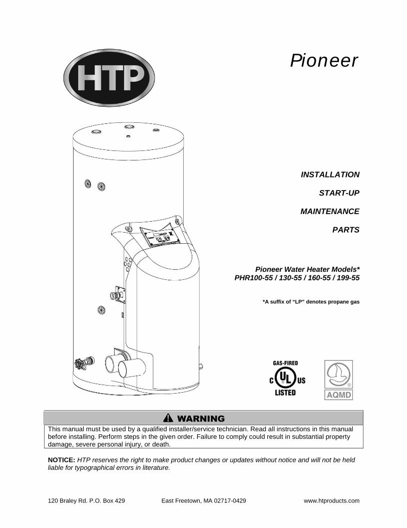
Figure 5 –Central Heating Detail – LP-325-F
NOTES: 1. This drawing is meant to show system piping concept only. Installer is responsible for all equipment & detailing required by local codes. 2. The minimum pipe size for connecting a SuperStor Ultra Indirect Water Heater is 1-inch. 3. The minimum pipe size for connecting the heater is 1.25-inch 4. Circulators are shown with isolation flanges and integral check valves. The alternative is standard flanges with full port ball valves and a separate flow check valve. Purge valves can be used with the circulator flanges as an alternative. 5. The anti-scald mixing valve is recommended if the DHW temperature is set above the factory setting of 119°F. 6. Install a minimum of 12 diameters of straight pipe upstream of all circulators. 7. Winterization: When winterizing, put a drain valve on both the supply and return between the union and the shut-off connection.

24
Figure 6 –Water Heater Detail
NOTES: 1. This drawing is meant to show system piping concept only. Installer is responsible for all equipment & detailing required by local codes. 2. The minimum pipe size for connecting a SuperStor Ultra Indirect Water Heater is 1-inch. 3. The minimum pipe size for connecting the heater is 1.25-inch 4. Circulators are shown with isolation flanges and integral check valves. The alternative is standard flanges with full port ball valves and a separate flow check valve. Purge valves can be used with the circulator flanges as an alternative. 5. The anti-scald mixing valve is recommended if the DHW temperature is set above the factory setting of 119°F. 6. Install a minimum of 12 diameters of straight pipe upstream of all circulators. 7. Winterization: When winterizing, put a drain valve on both the supply and return between the union and the shut-off connection.

25
Figure 7 – Cascaded System
NOTES: 1. This drawing is meant to show system piping concept only. Installer is responsible for all equipment & detailing required by local codes. 2. The minimum pipe size for connecting a SuperStor Ultra Indirect Water Heater is 1-inch. 3. The minimum pipe size for connecting the heater is 1.25-inch 4. Circulators are shown with isolation flanges and integral check valves. The alternative is standard flanges with full port ball valves and a separate flow check valve. Purge valves can be used with the circulator flanges as an alternative. 5. The anti-scald mixing valve is recommended if the DHW temperature is set above the factory setting of 119°F. 6. Install a minimum of 12 diameters of straight pipe upstream of all circulators. 7. Winterization: When winterizing, put a drain valve on both the supply and return between the union and the shut-off connection.

26
PART 7 – VENTING, COMBUSTION AIR AND CONDENSATE REMOVAL
The heater must be vented as detailed in this Venting Section. Ensure exhaust and intake piping complies with these instructions regarding vent system. Inspect finished combustion air intake and exhaust piping thoroughly to ensure all joints are well secured, airtight, and comply with all applicable code requirements, as well as with the instructions provided in this manual. Failure to provide a properly installed vent system will cause severe personal injury or death.
A. GENERAL
This vent system will operate with a positive pressure in the pipe. Do not connect vent connectors serving appliances vented by natural draft into any portion of mechanical draft systems operating under positive pressure. Follow the venting instructions below carefully. Failure to do so may result in substantial property damage, severe personal injury, or death. 1. Install the water heater venting system in accordance with these instructions and with the National Fuel Gas Code, ANSI Z223.1/NFPA 54, CAN/CGA B149, and/or applicable provisions of local building codes. 2. This water heater is a direct vent appliance and is listed as a Category IV appliance with Underwriters Laboratories, Inc. VENT AND INTAKE AIR VENT.
B. APPROVED MATERIALS FOR EXHAUST AND INTAKE AIR VENTS
APPROVED VENTING MATERIAL Item Material Standards for Installation in:
United States Canada
Vent or air pipe and fittings
PVC schedule 40/80 ANSI/ASTM D1785 CPVC and PVC venting must be ULC-S636 Certified. IPEX is an
approved manufacturer in Canada, supplying vent material listed to ULC-
S636.
PVC-DWV ANSI/ASTM D2665
CPVC schedule 40/80 ANSI/ASTM F441
Pipe cement/primer PVC ANSI/ASTM D2564 IPEX System 636 Cements & Primers CPVC ANSI/ASTM F493
Table 3
Do not use Foam Core Pipe in any portion of the exhaust piping from this heater. Use of Foam Core Pipe may result in substantial property damage, severe personal injury, or death.

27
C. EXHAUST AND INTAKE AIR VENT PIPE LOCATION
1. DETERMINE EXHAUST VENT LOCATION
Both exhaust and intake air vents must exit from the same side of the building to assure correct appliance operation.
a. The vent piping for this water heater is approved for zero clearance to combustible construction. b. See illustration within this section of clearances for location of exit terminals of direct-vent venting systems. c. This water heater vent system shall terminate at least 3 feet (0.9 m) above any forced air intake located within 10 ft (3 m). Note: this does not apply to the combustion air intake of a direct-vent appliance. d. Provide a minimum of 1 foot distance from any door, operable window, or gravity intake into any building. e. Provide a minimum of 1 foot clearance from the bottom of the exhaust above the expected snow accumulation level. Snow removal may be necessary to maintain clearance. f. Provide 4 feet horizontal clearance from electrical meters, gas meters, gas regulators, relief equipment, exhaust fans and inlets. In no case shall the exit terminal be above or below the aforementioned equipment unless the 4 foot horizontal distance is maintained. g. When adjacent to a public walkway, locate exit terminal at least 7 feet above grade. h. Do not locate the exhaust directly under roof overhangs to prevent icicles from forming. i. Provide 4 feet clearance from the inside corner of vertical walls, chimneys, etc., as well as horizontal corners created by roof overhangs.
2. DETERMINE AIR INTAKE VENT LOCATION
a. Provide 1 foot clearance from the bottom of the intake air vent and the level of maximum snow accumulation. Snow removal may be necessary to maintain clearances. b. Do not locate intake air vent in a parking area where machinery may damage the pipe. c. When venting with a two pipe system, maximum distance between intake air vent and exhaust vent is 6 feet (1.8 m). Minimum distance between exhaust vent and intake air vent on single water heater is 10” (0.255 m) center-to-center. Minimum distance between exhaust vents and intake air vents on multiple water heaters is 10” (0.255 m) center-to-center.
28
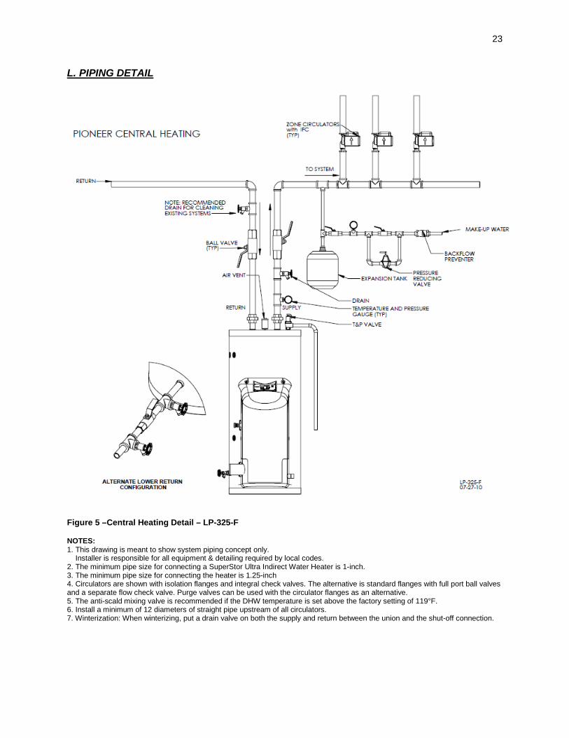
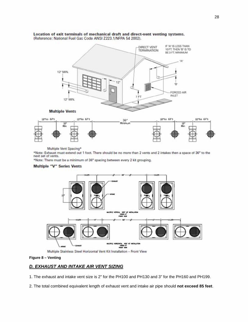
Figure 8 – Venting
D. EXHAUST AND INTAKE AIR VENT SIZING 1. The exhaust and intake vent size is 2" for the PH100 and PH130 and 3" for the PH160 and PH199. 2. The total combined equivalent length of exhaust vent and intake air pipe should not exceed 85 feet.

29
a. The equivalent length of elbows, tees, and other fittings are listed in the Friction Loss Table below:
FRICTION LOSS EQUIVALENT IN PIPING AND FITTINGS
FITTINGS OR PIPING EQUIVALENT FEET 2” 3” 4”
90 DEGREE ELBOW* 5’ 5’ 3’ 45 DEGREE ELBOW 3’ 3’ 1’
COUPLING 0’ 0’ 0’ AIR INLET TEE 0’ 0’ 0’
STRAIGHT PIPE 1’ 1’ 1’ CONCENTRIC VENT
KIT 3’ 3’ N/A
V500 2’ VENT KIT 1’ N/A N/A V1000 3’ VENT KIT N/A 1’ 1’ V2000 4’ VENT KIT N/A 1’ 1’
Table 4 - *Friction loss for long radius elbow is 1 foot less.
b. For example: If the exhaust vent has two 90° elbows and 10 feet of PVC pipe we will calculate: Exhaust Vent Pipe Equivalent Length = (2x5)+10=20 feet. Further, if the intake air vent pipe has two 90° elbows, one 45° elbow and 10 feet of PVC pipe, the following calculation applies: Intake Air Vent Pipe Equivalent Length = (2x5)+3+10=23 feet. Finally, if a concentric vent kit is used we find: Total Combined Equivalent Length = 20+23+3=46 feet. Therefore, the total combined equivalent length is 46 feet which is well below the maximum of 85 feet. c. The intake air vent pipe and the exhaust vent are intended to penetrate the same wall or roof of the building. d. Effort should be made to keep a minimum difference in equivalent length between the intake air vent pipe and the exhaust vent.
3. The minimum combined equivalent length is 16 equivalent feet.
E. LONGER VENT RUNS 1. The maximum combined equivalent length can be extended by increasing the diameter of both exhaust vent and intake air vent pipe equally. However, the transitions should begin a minimum of 15 equivalent feet from the water heater.
a. The maximum equivalent length for increased diameter vent pipes is 125 feet. b. Transitions should always be made in vertical sections of pipe to prevent the condensate from pooling in the vent pipe.
VENT CONNECTION REDUCING COUPLING VENT TRANSITION
2” 3” X 2” 3” 3” 4” X 3” 4”
Table 5 – Vent Run Transition
c. If the transition occurs at a distance greater than 15 equivalent feet from the water heater, the maximum equivalent length will be reduced.

30
TRANSITION POINT (FT. FROM WATER HEATER)
TEL OF OVERSIZED VENT PIPE (FT.)*
MAXIMUM TEL OF ALL VENT PIPE (FT.)
15 95 125 20 77-1/2 117-1/2 25 60-1/2 110-1/2 30 43 103 35 26 96 40 8-1/2 88-1/2
NONE 0 85 Table 6 – TEL = Total Equivalent Length *Oversized vent pipe diameter is 1” or greater than factory supplied connection.
F. EXHAUST VENT AND INTAKE AIR PIPE INSTALLATION
All joints of positive pressure vent systems must be sealed completely to prevent leakage of flue products into living space. 1. Use only solid PVC or CPVC pipe. FOAM CORE PIPING IS NOT APPROVED. 2. Remove all burrs and debris from joints and fittings. 3. All joints must be properly cleaned, primed, and cemented. Use only cement and primer approved for use with the pipe material. Cement must conform to ASTM D2564 for PVC and ASTM F493 for CPVC pipe. 4. Horizontal lengths of exhaust vent must slope back towards the water heater not less than ¼" per foot to allow condensate to drain from the vent pipe. 5. All piping must be fully supported. Use pipe hangers at a minimum of 4 foot intervals to prevent sagging of the pipe where condensate may form. 6. Do not use the heater to support any piping. 7. A screened straight coupling is provided with the heater for use as an outside exhaust termination. 8. A screened inlet air tee is provided with the heater to be used as an outside intake termination. 9. The following information on Table 5-8 lists optional intake air/exhaust vent terminations available from HTP.
DESCRIPTION STOCK CODE 2” PVC CONCENTRIC VENT TERMINATION KIT KGAVT0501CVT 3” PVC CONCENTRIC VENT TERMINATION KIT KGAVT0601CVT 2” STAINLESS STEEL VENT TERMINATION KIT V500 3” STAINLESS STEEL VENT TERMINATION KIT V1000 4” STAINLESS STEEL VENT TERMINATION KIT V2000
Table 7

31
G. VENTING DRAWINGS
1. DIRECT VENT INSTALLATION OF EXHAUST AND INTAKE If installing a direct vent option, combustion air must be drawn from the outdoors directly into the appliance intake, and exhaust must terminate outside. There are three basic direct vent options detailed in this manual: 1. Side Wall Venting, 2. Roof Venting, and 3. Unbalanced Venting. Be sure to locate the heater such that the air intake and exhaust vent piping can be routed through the building and properly terminated. Different vent terminals can be used to simplify and eliminate multiple penetrations in the building structure (see Optional Equipment in Venting Section). The air intake and exhaust vent piping lengths, routing and termination methods must all comply with the methods and limits given in the Venting section, Part 8 of this manual. When installing a combustion air intake from outdoors, care must be taken to utilize uncontaminated combustion air. NOTE: To prevent combustion air contamination, see Table 1.
Figure 9 NOTE: This drawing is meant to demonstrate system venting only. The installer is responsible for all equipment and detailing required by local codes.

32
Figure 10 NOTE: This drawing is meant to demonstrate system venting only. The installer is responsible for all equipment and detailing required by local codes.

33
Figure 11 NOTE: This drawing is meant to demonstrate system venting only. The installer is responsible for all equipment and detailing required by local codes.
34
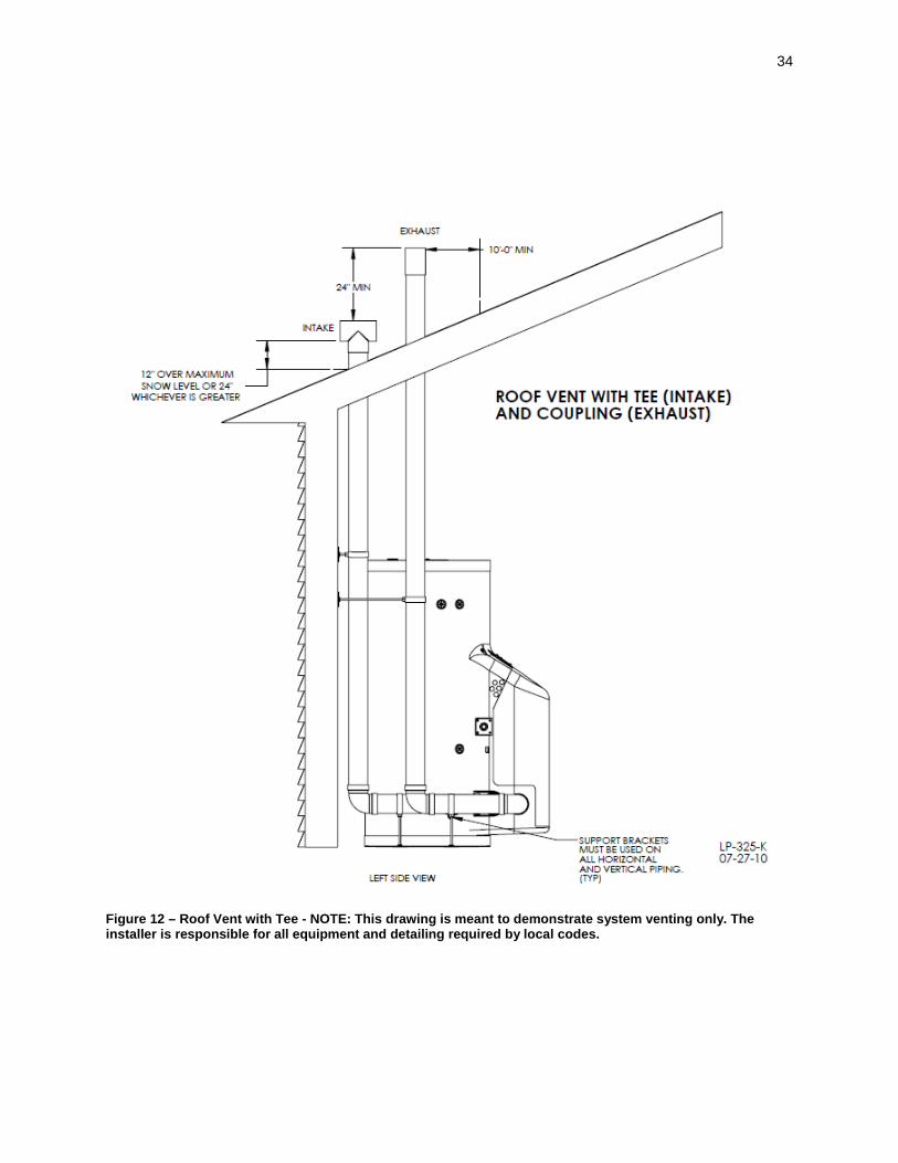
Figure 12 – Roof Vent with Tee - NOTE: This drawing is meant to demonstrate system venting only. The installer is responsible for all equipment and detailing required by local codes.

35
Figure 13 NOTE: This drawing is meant to demonstrate system venting only. The installer is responsible for all equipment and detailing required by local codes.

36
Figure 14 NOTE: This drawing is meant to demonstrate system venting only. The installer is responsible for all equipment and detailing required by local codes.

37
2. INDOOR COMBUSTION AIR INSTALLATION IN CONFINED OR UNCONFINED SPACE This heater requires fresh, uncontaminated air for safe operation and must be installed in a mechanical room where there is adequate combustion and ventilating air. NOTE: To prevent combustion air contamination, see Table 1.
Combustion air from the indoor space can be used if the space has adequate area or when air is provided through a duct or louver to supply sufficient combustion air based on the appliance input. Never obstruct the supply of combustion air to the appliance. If the appliance is installed in areas where indoor air is contaminated (see Figure 15) it is imperative that the appliance be installed as direct vent so that all combustion air is taken directly from the outdoors into the appliance intake connection. Unconfined space is space with volume not less than 50 cubic feet per 1,000 Btu/hour (4.8 cubic meters per kW) of the total input rating of all fuel-burning appliances installed in that space. Rooms connected directly to this space, through openings not furnished with doors, are considered part of the space. Confined space is space with volume less than 50 cubic feet per 1,000 Btu/hour (4.8 cubic meters per kW) of the total input rating of all fuel-burning appliances installed in that space. Rooms connected directly to this space, through openings not furnished with doors, are considered part of the space. When drawing combustion air from inside a conventionally constructed building to a confined
space, such space should be provided with two permanent openings: one located 6” (15 cm) below the space ceiling, the other 6” (15cm) above the space floor. Each opening should have a free area of one square inch per 1,000 Btu/hr (22cm2/kW) of the total input of all appliances in the space, but not less than 100 square inches (645cm2). If the confined space is within a building of tight construction, air for combustion must be obtained from the outdoors as outlined in the Venting section of this manual.
Figure 15 – LP-179-AA

38
Figure 16 NOTE: This drawing is meant to demonstrate system venting only. The installer is responsible for all equipment and detailing required by local codes.

39
H. EXHAUST VENT AND INTAKE AIR PIPE INSTALLATION 1. Use only solid PVC or CPVC pipe. FOAM CORE PIPING IS NOT APPROVED. 2. Remove all burrs and debris from joints and fittings. 3. All joints must be properly cleaned, primed, and cemented. Use only cement and primer approved for use with the pipe material. Cement must conform to ASTM D2564 for PVC and ASTM F493 for CPVC pipe.
All joints of positive pressure vent systems must be sealed completely to prevent leakage of flue products into living space. 4. Horizontal lengths of exhaust vent must slope back towards the water heater not less than ¼" per foot to allow condensate to drain from the vent pipe. If exhaust pipe must be piped around an obstacle that results in creation of a low point, condensate will collect in this low point and form a blockage. This condensate must be drained away using a field-installed condensate drain assembly. 5. All piping must be fully supported. Use pipe hangers at a minimum of 4 foot intervals to prevent sagging of the pipe where condensate may form. 6. Do not use the heater to support any piping. 7. A screened straight coupling is provided with the heater for use as an outside exhaust termination. 8. A screened inlet air tee is provided with the heater to be used as an outside intake termination. 9. The following information on Table 5-8 lists optional intake air/exhaust vent terminations available from HTP.
DESCRIPTION STOCK CODE 2’ PVC CONCENTRIC VENT TERMINATION KIT KGAVT0501CVT 3’ PVC CONCENTRIC VENT TERMINATION KIT KGAVT0601CVT 2” STAINLESS STEEL VENT TERMINATION KIT V500 3” STAINLESS STEEL VENT TERMINATION KIT V1000 4” STAINLESS STEEL VENT TERMINATION KIT V2000
Table 8
I. REMOVING AN EXISTING WATER HEATER When removing an existing heater, the follow the steps below with each appliance remaining connected to the common venting system in operation, while other appliances remaining connected to common venting system are not operating. 1. Seal any unused openings in the common venting system. 2. Visually inspect the venting system for proper size and horizontal pitch to determine if there is blockage, leakage, corrosion or other deficiencies that could cause an unsafe condition. 3. If practical, close all building doors, windows and all doors between the space in which the appliance remains connected to the common venting system located and other spaces in the building. Turn on clothes dryers and any appliances not connected to the common venting system. Turn on any exhaust

40
fans, such as range hoods and bathroom exhausts, at maximum speed. Do not operate a summer exhaust fan. Close all fireplace dampers. 4. Place in operation the appliance being inspected. Follow the lighting instructions. Adjust the thermostat so the appliance will operate continuously. 5. Test for spillage at the draft hood relief opening after 5 minutes of main burner operation. Use the flame of a match or candle or smoke from a cigarette. 6. After it has been determined that each appliance remaining connected to common venting system properly vents when tested as outlined, return doors, windows, exhaust fans, fireplace dampers and any other gas burning appliance to their previous condition of use. 7. Any improper operation of the common venting system should be corrected to conform to the National Fuel Gas Code, ANSI Z223.1. When resizing any portion of the common venting system, the system should approach the minimum size as determined using the appropriate tables in Appendix G in the National Fuel Gas Code, ANSI Z 223.1.
J. CONDENSATE REMOVAL SYSTEM This condensing high efficiency appliance has a condensate removal system. Condensate is water vapor derived from combustion products, similar to an automobile when it is initially started. It is very important that the condensate line is sloped down away from the heater and to a suitable drain. If the heater condensate outlet is lower than the drain, you must use a condensate removal pump (kit 554200 available from HTP). If required by local authorities, a condensate filter of lime crystals, marble, or phosphate chips will neutralize slightly acidic condensate. This can be installed in the field and purchased from HTP (7450P-212).
Plastic tubing must be the only material used for the condensate line. Steel, brass, copper or other materials will be subject to corrosion or deterioration. A second vent may be necessary to prevent a condensate line vacuum lock if a long horizontal run is used. An increase in condensate line diameter may be necessary to allow condensate to drain properly. Support of the condensate line may be necessary to avoid blockage of the condensate flow.
The condensate line must remain unobstructed. If allowed to freeze in the line or obstructed in any other manner, condensate can exit from the water heater tee, resulting in potential water damage to property. When installing a condensate pump, select one approved for use with condensing heaters and furnaces. The condensate pump should have an overflow switch to prevent property damage from spillage. Condensate from the heater will be slightly acidic (pH from 3.2 to 4.5). Install a neutralizing filter if required by local codes.

41
Figure 17 – Condensate Line Detail
NOTES: 1. Condensate line must be pitched at least 1/4" per foot to properly drain. If this cannot be done, or a very long length of condensate hose is used, you must increase the condensate line to a minimum of 1” ID and place a tee in the line after the condensate neutralizer to properly reduce vacuum lock in the drain line. 2. Plastic pipe should be the only material used for the condensate line. Steel, brass, copper, or other materials will be subject to corrosion or deterioration. 3. It is also very important that the condensate line is not exposed to freezing temperatures or any other type of blockage.
PART 8 – FIELD WIRING
ELECTRICAL SHOCK HAZARD – For your safety, turn off electrical power supply at service entrance panel before making any electrical connections to avoid possible electric shock hazard. Failure to do so can cause severe personal injury or death.
Wiring must be N.E.C. Class 1. If original wiring supplied with the heater must be replaced, use only TEW 105 oC wire or equivalent. Heater must be electrically grounded as required by National Electrical Code ANSI/NFPA 70 – Latest Edition.
A. INSTALLATION MUST COMPLY WITH: 1. National Electrical Code and any other national, state, provincial, or local codes or regulations. 2. In Canada, CSA C22.1 Canadian Electrical Code Part 1, and any local codes.
B. FIELD WIRING All connections made to the heater in the field are done on the field connection board located in the cabinet on the top left area of the unit. Multiple knockout locations are available to route field wires into and out of the cabinet.

42
The heater is capable of directly controlling 2 pumps when in standard mode and 3 pumps when configured as a cascade master heater. When configured as a standard unit, each pump output can provide a maximum of 3 amps at 120 volts. If pumps require more than this amount of power, an external contactor or motor starter is needed. If the heater is configured as a cascade master, the system pump output is a dry contact output capable of switching 5 amps at 120 volts in addition to the heater pump and DHW pump outputs sourcing 3 amps each. The field connection board has separate, clearly marked terminal strips for line voltage and low voltage wiring. Special jacks are provided for trouble-free cascade system wiring using standard CAT3 or CAT5 patch cables.
C. LINE VOLTAGE WIRING FOR STANDARD HEATER 1. Connect the incoming power wiring to the line voltage terminal strip in the field connection board at terminals 120V, Neutral, Ground. A line voltage fused disconnect switch may be required to be externally mounted and connected according to local codes that may apply. 2. Connect the central heating pump to the terminals marked 1 (HOT), 2 (NEUT), 3 (GND) in Figure 18. The connections shown are suitable for a maximum continuous pump draw of 3 amps at 120 volts. If the pump requires more current or voltage other than 120 volts, an external motor starter or contactor will be required.
3. If using DHW, connect the domestic hot water pump as shown to the terminals marked 4 (HOT), 5 (NEUT), 6 (GND). The connections shown are suitable for a maximum continuous pump draw of 3 amps at 120 volts. 4. If a pump requires more current or voltage other than 120 volts, an external motor starter or contactor will be required.
D. THERMOSTAT 1. Connect the room thermostat to the terminals marked 14 and 15 on the field connection board. Any dry contact closure across these terminals will cause the heater to run. Caution should be used to ensure neither of the terminals connects to the ground.
Figure 18 –Control Detail LP-325-P1

43
2. Mount the thermostat on an inside wall as centrally to the area being heated as possible, but away from drafts or heat producing devices such as television sets that could influence the ability of the thermostat to measure room temperature. 3. If the thermostat is equipped with an anticipator and it is connected directly to the heater, the anticipator should be set at .1 amps. If the thermostat is connected to other devices, the anticipator should be set to match the power requirements of those devices. See the instruction manual of connected devices for further information.
E. OUTDOOR SENSOR (OPTIONAL) 1. If an HTP 7250P-319 outdoor sensor is not used in this installation, move on to Section F. 2. Use a minimum 22 AWG wire for runs of 100 feet or less and minimum 18 AWG wire for runs of up to 150 feet. 3. Mount the outdoor sensor on an exterior surface of the building, preferably on the north side in an area that will not be affected by direct sunlight and will be exposed to varying weather conditions. NOTE: Follow instructions provided with the sensor for detailed mounting instructions. 4. When correctly mounted, connect sensor to terminals marked 12 and 13.
F. INDIRECT SENSOR (OPTIONAL) 1. If an indirect water tank is not used in the installation, move on to Section G. 2. The heater will operate an indirect fired water tank with either a thermostat type aquastat installed in the indirect tank or an HTP 7250P-325 tank sensor. When a tank sensor is used, the heater control will automatically detect its presence and a demand for heat from the indirect water tank will be generated when the tank temperature falls below the user set point by more than the user selectable offset. Demand will continue until the sensor measures that the indirect water tank temperature is above the set point. Connect the indirect tank sensor (7250P-325) or mechanical aquastat to the terminals marked 10 and 11 on the field connection board.
G. 0-10 VOLT BUILDING CONTROL SIGNAL (OPTIONAL) 1. If a 0-10 volt building management system is not used in the installation, move on to Section H. 2. A signal from a building management system may be connected to the heater to enable remote control. This signal should be a 0-10 volt positive-going DC signal. 3. When this input is enabled using the installer menu, a building control system can be used to control either the set point temperature or the heat output of the heater. The control interprets the 0-10 volt signal as follows; when the signal is between 0 and 1.5 volts, the heater will be in standby mode, not firing. When the signal rises above 1.5 volts, a demand for heat is started. As the signal continues to rise towards its maximum of 10 volts, the heater will increase either its set point temperature or firing rate depending on the setting of function 17 in the installer menu. See Part 11 for details on the setting of functions 16 and 17 for this option. 4. Connect a building management system or other auxiliary control signal to the terminals marked 16 (0-10 VOLT +) and 17 (0-10 VOLT –) in the electrical junction box caution should be used to ensure that the 16 (0-10 VOLT +) connection does not become connected to ground.

44
H. UL353 LOW WATER CUT-OFF INTERFACE KIT (OPTIONAL) 1. If an HTP 7450P-255 UL353 Low Water Cut-Off (LWCO) Interface Kit is not used, move on to Section I. 2. The control box of the kit should be mounted to the left side of the heater near the low water cut-off probe, which is located near the outlet nipple of the heater. 3. Follow the complete instructions included in the kit for proper installation.
I. WIRING OF CASCADE SYSTEM COMMUNICATION BUS 1. Use standard CAT3 or CAT5 computer network patch cables to connect the communication bus between each of the heaters. These cables are readily available at any office supply, computer, electronic, department or discount home supply store in varying lengths. If you possess the skills you can also construct custom length cables. 2. It is recommended to use the shortest length cable that will reach between the heaters and create a neat installation. Do not run unprotected cables across the floor where they may become wet or damaged. Avoid running communication cables parallel and close to or against high voltage (120 volt or greater) wiring. HTP recommends that the maximum length of communication bus cables not exceed 200 feet. 3. Route the communication cables through one of the knockouts in the cabinet. 4. Connect the heaters in a daisy chain configuration. It is best to wire the heaters using the shortest wire runs rather than trying to wire them in the order that they are addressed. The communication bus jacks on the customer connection panel are interchangeable so you can use either one or both in any order to connect the cable. If you have connected the heaters to each other properly (see Figure 7 – Cascaded System, p. 25), two of the heaters will have single open connection ports.
Figure 19

45
J. CASCADE MASTER PUMP AND SENSOR WIRING
1. Connect the system pump hot wire to the terminal marked 8. 2. Connect the system pump neutral to the terminal 2 and the pump ground wire to terminal 3. 3. Connect a jumper wire from the 120 VOLT terminal to terminal 9. 4. Connect the heater pump to the terminals marked 1, 2, and 3. 5. Connect the system pipe sensor to the terminals marked 10 and 11. 6. Connect the outdoor sensor (if used) to the terminals marked 12 and 13. 7. Connect the signal to start the system to the terminals marked 14 and 15. NOTE: This signal can come from a room thermostat or a dry contact closure. No power of any voltage should be fed into either of these terminals.
Figure 20 – Cascade Master Detail – LP-325-P3

46
K. CASCADE FOLLOWER PUMP AND SENSOR WIRING
1. Connect the heater pump to the terminals labeled 1, 2, and 3. If you are using an indirect fired water tank connected directly to the follower heater connect the pump for it to the 4, 5, and 6 terminals. 2. An alarm bell or light can be connected to the alarm contacts of the follower heater. In the event of an alarm, the normally open alarm contact may be used to turn a device on. The normally closed alarm contact may be used to turn a device off if the heater goes into lockout mode. The alarm contacts are rated 5 amps at 120 VAC. 3. To connect an alarm device that will use the normally open contact, connect the power for the device to terminal 8. Connect the alarm device hot wire to terminal 9. Connect the neutral or return of the alarm device to the neutral or return of the power for the alarm device. 4. To connect a device that should be powered off during a heater lockout condition, follow the same instructions as above except use terminal 7 rather than terminal 9. NOTE: In a cascade system the alarm output of the heater addressed as #1 will also be active if the master heater has a lockout condition. The alarm output of heaters addressed as 2-7 will only activate an alarm if a lockout condition occurs on that specific heater.
PART 9 – START-UP PREPARATION
Thoroughly clean and flush any system that has used glycol before installing the heater. Provide the customer with a material safety data sheet (MSDS) on the fluid used.
Figure 21 – Cascade Follower Detail – LP-325-P2

47
Do not use petroleum-based cleaning or sealing compounds in heater system. Damage to elastomer seals and gaskets in system could occur, resulting in substantial property damage.
A. CHECK/CONTROL WATER CHEMISTRY Water pH between 6.0 and 8.0 1. Maintain heater water pH between 6.0 and 8.0. Check with litmus paper or have chemically analyzed by a water treatment company. 2. If the pH differs from above, consult local a water treatment company for treatment required. Hardness less than 7 grains Consult local water treatment companies in circumstances of unusually hard water (above 7 grains hardness). Chlorine concentration less than 200 ppm 1. Filling with chlorinated fresh water should be acceptable since drinking water chlorine levels are typically less than 5 ppm. 2. Do not use the heater to directly heat swimming pool or spa water. 3. Do not fill heater or operate with water containing chlorine in excess of 200 ppm. Clean system to remove sediment 1. You must thoroughly flush the system (without the heater connected) to remove sediment. The high-efficiency heat exchanger can be damaged by buildup or corrosion due to sediment. 2. For zoned systems, flush each zone separately through a purge valve. (If purge valves and isolation valves are not already installed, install them to properly clean the system.) 3. Flush system until water runs clean and you are sure piping is free of sediment.
B. FREEZE PROTECTION (WHEN USED) 1. Determine freeze protection fluid quantity following fluid manufacturer instructions. Remember to include expansion tank water content. 2. Local codes may require back flow preventer or disconnect from city water supply. 3. When using freeze protection fluid with automatic fill, install a meter to monitor water makeup. Freeze protection fluid may leak before water begins to leak, causing concentration to drop, reducing the freeze protection level. Test / replace freeze protection fluid 1. Follow fluid manufacturer instructions to verify inhibitor level and other fluid characteristics are satisfactory.

48
2. Freeze protection fluid must be replaced periodically due to degradation of inhibitors over time. Follow all fluid manufacturer instructions.
C. FILL AND TEST WATER SYSTEM 1. Fill system only after ensuring the water meets the requirements of this manual. 2. Close manual and automatic air vents and heater drain valve. 3. Fill to correct system pressure. Correct pressure will vary with each application.
a. Typical cold water fill pressure for a residential system is 12 psi. b. Pressure will rise when heater is turned on and system water temperature increases. Operating pressure must never exceed 25 psig.
4. At initial fill and during heater startup and testing, check system thoroughly for any leaks. Repair all leaks before proceeding further. 5. The system may have residual substances that could affect water chemistry. After the system has been filled and leak tested, verify water pH and chlorine concentrations are acceptable.
D. PURGE AIR FROM WATER SYSTEM 1. Connect a hose to the purge valve and route hose to an area where water can drain and be seen. 2. Close the heater or system isolation valve between the purge valve and fill connection to the system. 3. Close zone isolation valves. 4. Open quick-fill valve on cold water makeup line. 5. Open purge valve. 6. One zone at a time, open the isolation valves. Allow water to run through the zone, pushing out the air. Run until no noticeable air flow is present. Close the zone isolation valves and proceed with the next zone. Follow this procedure until all zones are purged. 7. Refill to correct pressure.
E. CHECK THERMOSTAT CIRCUIT(S) 1. Disconnect the two external wires connected to the heater thermostat terminals (low voltage terminal strip). 2. Connect a voltmeter across these two incoming wires with power applied to thermostat circuits. Close each thermostat, zone valve and relay in the external circuit one at a time and check the voltmeter reading across the incoming wires. 3. There should NEVER be a voltage reading. 4. If a voltage does occur under any condition, check and correct the external wiring. (This is a common problem when using 3-wire zone valves). 5. Once the external thermostat circuit wiring is checked and corrected if necessary, reconnect the external thermostat circuit wires to heater low voltage terminal strip.

49
F. FINAL CHECKS BEFORE STARTING HEATER 1. Read Startup Procedures within this manual for proper steps to start heater. (See Startup Report to record steps for future reference). 2. Verify heater and system are full of water and all system components are correctly set for operation. 3. Fill condensate trap with water. 4. Verify electrical connections are correct and securely attached. 5. Inspect intake piping and exhaust piping for signs of deterioration from corrosion, physical damage or sagging. Verify intake and exhaust piping are intact and correctly installed per Venting section and local code.
PART 10 – START-UP PROCEDURE
FOR YOUR OWN SAFETY READ BEFORE OPERATING
Before starting the heater, and during initial operation, smell near the heater and around the floor for gas odorant or any unusual odor. Do not proceed with startup if there is any indication of a gas leak. Repair any leaks at once.
This appliance does not have a pilot. It is equipped with an ignition device which automatically lights the burner. Do not try to light the burner by hand.
A. OPERATING INSTRUCTIONS If you smell gas, STOP. Follow listed safety instructions. If you do not smell gas, follow the next steps. 1. Turn on all electrical power to the appliance.
IF THE INFORMATION IN THIS MANUAL IS NOT FOLLOWED EXACTLY, A FIRE OR EXPLOSION
MAY RESULT, CAUSING PROPERTY DAMAGE, PERSONAL INJURY, OR LOSS OF LIFE. DO NOT STORE GASOLINE OR OTHER FLAMMABLE VAPORS AND LIQUIDS IN THE VICINITY OF THIS OR
ANY OTHER APPLIANCE.
WHAT TO DO IF YOU SMELL GAS • Do not try to light any appliance. • Do not touch any electrical switch. • Do not use any phone in your building. • Immediately call your gas supplier from a neighbor’s phone. Follow the gas supplier’s
instructions. • If you cannot reach your gas supplier, call the fire department. Installation and service must be
provided by a qualified installer, service agency, or the gas supplier.

50
2. Adjust the temperature set point of the heater if desired. The factory default setting is 180oF. If changes are necessary, follow, “Adjusting the Set point”, below. 3. Set the thermostat to create a demand for heat. 4. If the appliance fails to start, refer to the Troubleshooting section in the back of this manual.
B. CASCADE SYSTEM 1. If the heater is used alone, skip this section. 2. Programming the Master Heater
a. Make sure there is no demand for heat being supplied to the heater. b. Apply power to the heater. c. Enter the Installer Menu following instructions in Part 11 of this manual. d. Verify that parameter 15 is set to 0. This makes the Master Heater address 0. NOTE: The Master Heater MUST be addressed as 0. e. Set parameter 23 from 0 to 1. This makes this heater the Master Heater.
f. Exit the installer menu. NOTE: The temperature set point of the Master must match the follower heater set point in order for the system to operate properly. 3. Follower Heaters NOTE: READ THE NOTES BELOW BEFORE PROGRAMMING FOLLOWER HEATERS:
• The heater addressed as 1 will share its alarm output with the Master Heater. • If one of the follower heaters has an indirect fired water heater connected to it, the address of this
heater must be 2 or greater. • It is recommended but not necessary to address heaters in the order that they are wired. • No two heaters can have the same address. • It is not required to use all consecutive address numbers. Example: In a 2 heater system with an
indirect connected to the follower, the follower address would be 2 (address 1 not used). 4. To program follower heater(s):
a. Make sure there is no demand for heat being supplied to the Master Heater. b. Apply power to the follower heater you are working on.
c. Enter the installer Menu following instructions in part 11 of this manual. d. Set parameter 15 to 1 for the first follower, 2 for the second follower, etc. depending on which heater you are programming. e. Take into account the notes above and set parameter 23 to desired appliance address. f. Exit the installer menu.
NOTE: The temperature set point of the follower must match the Master Heater set point in order for the system to operate properly.
C. ADJUSTING THE SET POINT Before you change the temperature from the factory setting of 180o, make sure that none of the thermostats are calling for heat. The controller will not memorize a program setting while in a heating cycle. To access and scroll through additional setting options, press {S3}.

51
1. Press {S3} once to access |C|, Heater Temperature Set Point. To adjust the temperature of the heater, simply press in the {S3} key for three seconds until you see a flashing (C) then an alternating value of (180). This number is the factory set point of 180oF. To change the temperature, push either {S1} or {S2} on the display. The {S1} button decreases and {S2} increases the set point temperature. The set point temperature can be set as low as 50oF or as high 185oF. Changes are directly stored and the display returns to normal mode after one minute. 2. Press {S3} a second time. The heater will now display |Ch| and an alternating value of 15. This is the Heater Differential Set Point. This function allows the installer to adjust the activation of the burner based on the differential temperature setting of the heater. The burner will not start until the outlet water temperature reaches a temperature equal to the setting for the heater, minus the differential. EXAMPLE: The heater is set to heat at 180°F and the differential is set at 15°F. The burner will not start until the outlet temperature of the system reaches 164°F (180° – 15° = 165°). To adjust, press either (S1} (Decrease Value) or {S2} (Increase Value). Ranges 5° F to 30° F.
3. NOTE: Only in use if using an indirect storage tank. Press {S3} a third time and you will see the Indirect Temperature Set Point |de| and an alternating value of 119. Range 95 – 180. To adjust, press either {S1} (Decrease Value) or {S2} (Increase Value). 4. Press {S3} a fourth time to access |dh|, the Indirect Differential Set Point. This function allows the installer to adjust the activation of the DHW call based on the differential temperature setting for the indirect tank. The pump will not start until the indirect water temperature reaches a temperature equal to the setting for the indirect, minus the indirect differential. Range 1 – 18. Default 7. EXAMPLE: The indirect is set to heat at 130oF and the differential is set to 10oF. The DHW pump will not start until the outlet temperature of the system reaches 119oF (130o – 10o = 120o). 5. Press {S3} a fifth time to access the final adjustment in this mode – |t|, the Temperature Measurement in Fahrenheit to Celsius. To change value, press either {S1} or {S2} to change the measurement from F (Fahrenheit) to C (Celsius).
D. STATUS MENU Installers are also able to check the current status of the heater parameters by pressing {S4} for 3 seconds. Once activated, the display will show |d1| alternating value of the actual outlet temperature. Actual values are displayed for each function. To view the next value, simply press the {S4} key. Listed below are the values which can be displayed. These values cannot be changed. To exit this menu, simply press {S3} to resume normal operation. Function – Value To toggle between values press {S1} to go down and {S4} to go up. The first function you will see is: |d1| — Actual temperature from top sensor |d2| — Actual temperature from bottom sensor |d3| — Actual tank temperature if an indirect sensor is used. |d4| — Not used
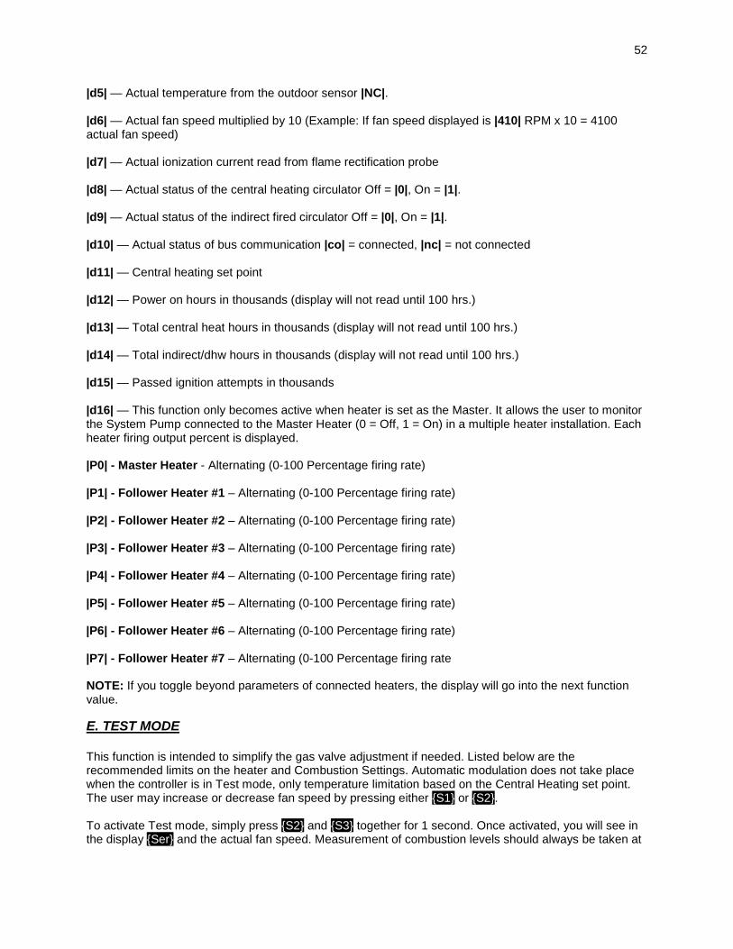
52
|d5| — Actual temperature from the outdoor sensor |NC|. |d6| — Actual fan speed multiplied by 10 (Example: If fan speed displayed is |410| RPM x 10 = 4100 actual fan speed) |d7| — Actual ionization current read from flame rectification probe |d8| — Actual status of the central heating circulator Off = |0|, On = |1|. |d9| — Actual status of the indirect fired circulator Off = |0|, On = |1|. |d10| — Actual status of bus communication |co| = connected, |nc| = not connected |d11| — Central heating set point |d12| — Power on hours in thousands (display will not read until 100 hrs.) |d13| — Total central heat hours in thousands (display will not read until 100 hrs.) |d14| — Total indirect/dhw hours in thousands (display will not read until 100 hrs.) |d15| — Passed ignition attempts in thousands |d16| — This function only becomes active when heater is set as the Master. It allows the user to monitor the System Pump connected to the Master Heater (0 = Off, 1 = On) in a multiple heater installation. Each heater firing output percent is displayed. |P0| - Master Heater - Alternating (0-100 Percentage firing rate) |P1| - Follower Heater #1 – Alternating (0-100 Percentage firing rate) |P2| - Follower Heater #2 – Alternating (0-100 Percentage firing rate) |P3| - Follower Heater #3 – Alternating (0-100 Percentage firing rate) |P4| - Follower Heater #4 – Alternating (0-100 Percentage firing rate) |P5| - Follower Heater #5 – Alternating (0-100 Percentage firing rate) |P6| - Follower Heater #6 – Alternating (0-100 Percentage firing rate) |P7| - Follower Heater #7 – Alternating (0-100 Percentage firing rate NOTE: If you toggle beyond parameters of connected heaters, the display will go into the next function value.
E. TEST MODE This function is intended to simplify the gas valve adjustment if needed. Listed below are the recommended limits on the heater and Combustion Settings. Automatic modulation does not take place when the controller is in Test mode, only temperature limitation based on the Central Heating set point. The user may increase or decrease fan speed by pressing either {S1} or {S2}. To activate Test mode, simply press {S2} and {S3} together for 1 second. Once activated, you will see in the display {Ser} and the actual fan speed. Measurement of combustion levels should always be taken at

53
the highest and lowest fan speed. After 20 minutes, Test mode stops automatically. To exit Test Mode manually, press {S1} and {S2} together for 1 second.
COMBUSTION SETTINGS HIGH FIRING RATES and LOW FIRING RATES ON ALL MODELS
NATURAL GAS PROPANE LP Low High Low high
Carbon Monoxide (CO%) 0 – 10 ppm 0 – 20 ppm 0 – 10 ppm 0 – 20 ppm
Carbon Dioxide (CO2%) 9% - 10 ½% 9% - 10 ½% 9 ½% - 11% 9 ½% - 11%
Table 9
FAN SPEEDS BTU IGNITION MIN MAX
100,000 3000 2000 5400 130,000 3000 2000 6950 160,000 3000 2000 6850 199,000 3000 2000 8500
Table 10
F. PURGE AIR FROM WATER SYSTEM Disconnect the wires connected to the THERMOSTAT terminals of the field connection board. Apply power to the appliance. The display will show the appliance water temperature. Press the {S1} and {S3} keys simultaneously and hold for 1 second. The display will begin alternating between SEP and CH, and the central heating pump will come on. If you press {S2} again, the central heating pump will shut off, the display will begin alternating between SEP and DH, and the DHW pump will come on. If the appliance is a cascade master and you press {S2} again, the DHW pump will shut off, the display will begin alternating between SEP and Sh, and the system pump will come on. You can use the {S1} and {S2} keys to toggle between running each pump in the system as required to help bleed out all entrapped air. Some good indicators that air is removed include the absence of gurgling noises in the pipes and pump operation becoming very quiet. Press {S1} and {S2} together at any time to return the control to normal operation.
PART 11 – PROGRAMMING THE HEATER The control allows the installer to set system limits and the heat curve for the Heater. These system limits should not be changed by the user. It is important to document your settings within this manual after you program the system parameters for future reference.
A. PROGRAM ACCESS To start, press and hold {S3} and {S4} simultaneously for three seconds. You will notice the display change to |000|. Then, press and hold {S1} until you see |925|. (If you go past |925|, you can use {S2} to decrease the number.) This is the pass code. To confirm that the pass code is correct, press and hold the {S3} key for 1 second. If the pass code is entered incorrectly, the controller program function will cancel and return to normal operation. If the code is entered correctly, the control will switch off the gas valve and purge fan while showing a solid - - - in the display. The display will then show a |1| alternating to |de|. This first function verifies that the control will function with the SuperStor Indirect Fired Water Heater.
B. PROGRAM SYSTEM SETTINGS Next you will have to press the {S3} key to move through each function. To increase or decrease a value, you will need to press either the {S1} key or {S2} key to change the default values. If there is no key

54
action for 1 minute, the display returns to normal operation. Changes are effective immediately but not directly stored until the {S4} key is pressed down for 3 seconds then the new values are stored. Listed below are the varieties of functions the installer can program. DEFAULT
FUNCTION VALUE DESCRIPTION
1 |de| N/A 2 149oF N/A
3 160oF Maximum set point for indirect water heater temperature
(NOTE: Does not apply if used with mechanical control) Range: 95oF to 185oF
4 36oF N/A
5 7oF Change differential in indirect water heater Range: 1oF to 18oF
6 0 min. Changes the indirect circulator post purge time once the sensor is satisfied.
(NOTE: Post purge time should be set no greater than 5 minutes.) Range: 0 to 10 minutes
7 68oF Warm weather shutoff Range: 41oF to 122oF
8 5oF Changes the minimum outside design temperature Range: -49oF to 32oF
9 180oF Changes design supply water temperature based on minimum outside design temperature Range: 77oF to 180oF
10 68oF Changes maximum outside design temperature for central heating Range: 32oF to 95oF
11 95oF Changes design supply water temperature based on maximum outside design temperature Range: 32oF to 185oF
12 68oF Sets the lowest temperature on the heater for central heating Range: 32oF to 185oF
13 0 min. Changes central heating circulator post purge time once thermostat is satisfied. Range: 0 to 10 minutes
14 30 min. Sets maximum run time for the indirect water heater and minimum run time for central heating. Range: 0 to 60 minutes
15 0 Bus address (0 = zone master 1 – 8 = cascade slave)
16 0 Allows the installer to connect a 0-10 volt directly from Building Management System.
To activate, change value to 2. WARNING: Values 1 and 3 are not to be programmed into the board. Range: 0 - 3.
17 0 Allows the user to control the function of the 0-10 volt input
0 = Appliance Temperature 1 – Appliance Power
18 1
Step Modulation – Regulates the burner output in 6 steps in 1 minute intervals. This reduces short cycling. 1 = On 0 = Off
19 185oF Indirect Heater Set point (flow) Temperature Default = 95oF to 185oF
20 3 N/A
21 0
Allows the installer to set the control to display FOU error. If outdoor sensor is open or shorted, FOU error does not prevent the appliance from running.
0 = No FOU displayed. 1 = FOU displayed if outdoor sensor is shorted or open.
22 100% Maximum appliance output percentage. Default = 100%. This parameter can be adjusted to lower
the maximum appliance output if necessary. Range: 50 – 100%.
23 0 Cascade configuration (Default 0). Change this to 1 if the appliance is a cascade master.
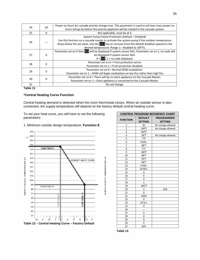
55
24 24 Power on hours for cascade priority change over. This parameter is used to set how many power on hours will go by before the priority appliance will be rotated in the cascade system.
25 0 Not applicable, must be at 0.
26 ---
System Pump Freeze Protection (Default – Disabled) Use this function on a cascade master to activate the system pump if the outdoor temperature
drops below the set value. Use the S/2+ key to increase from the default disabled upward to the desired temperature. Range: (---disabled to 104oF).
27 0 Parameter set on 0 then E03 will be displayed if system sensor fails. Parameter set on 1, no code will
be displayed if system sensor fails. 0 = E03, 1 = no code displayed.
28 0 Parameter set on 0 = Frost protection active. Parameter set on 1 = Frost protection disabled.
29 0 Parameter set on 0 = Normal DHW modulation. Parameter set on 1 – DHW will begin modulation on low fire rather than high fire
30 0 Parameter set on 0 = There will be no extra appliance on the Cascade Master. Parameter set on 1 = Extra appliance is connected to the Cascade Master.
31 Do not change. Table 11
*Central Heating Curve Function Central heating demand is detected when the room thermostat closes. When an outside sensor is also connected, the supply temperature will depend on the factory default central heating curve. To set your heat curve, you will have to set the following parameters: 1. Minimum outside design temperature: Function 8.
Table 12 – Central Heating Curve – Factory Default
CONTROL PROGRAM REFERENCE CHART
FUNCTION DEFAULT SETTING
PROGRAMMED SETTING
1 de No change allowed 2 149oF No change allowed 3 160oF 4 36oF No change allowed 5 7oF 6 0 Min. 7 68oF 8 5oF 9 180oF
10 68oF 11 95oF 12 68oF 13 0 Min. 14 30 Min. 15 0 16 0 17 0 18 1 19 185oF 20 3 N/A 21 0 22 100% 23 0 24 24 hrs. 25 0 26 --- 27 0 28 0 29 0 30 0 31 N/A
Table 13

56
2. Design supply water temperature at the minimum design outside temperature: Function 9. 3. Maximum outside design temperature: Function 10. 4. Design supply water temperature at the maximum outside temperature: Function 11. NOTE: The homeowner can adjust the heat curve down by adjusting the central heating temperature to a lower setting.
PART 12 – TROUBLESHOOTING
A. HEATER ERROR CODE An error code may occur in the installation of the heater. This condition may lead to a lock out condition of the controller, which will need to be manually reset through the {S4} button. These temporary codes will help the installer correct the problem before going into a lock out condition, which will require a manual reset.
B. HEATER ERROR 1. When an error condition occurs the controller will display an error code on the display module. 2. These error codes and several suggested corrective actions are included in Table 15.
C. HEATER FAULT 1. When a fault condition occurs the controller will illuminate the red “fault” indication light and display a fault code in the format (Example: |F00|) on the display module. 2. Note the fault code and refer to Table 16 for an explanation of the fault code along with several suggestions for corrective actions. 3. Press the reset key to clear the fault and resume operation. Be sure to observe the operation of the unit to prevent a recurrence of the fault.
RESISTANCE TABLE FOR SUPPLY TEMPERATURE
SENSOR HIGH/LOW
TEMP. SENSOR TEMP. (oF)
RESISTANCE (ohms)
32 32550
41 25340
50 19870
59 15700
68 12490
77 10000
86 8059
95 6535
104 5330
113 4372
122 3605
131 2989
140 2490
149 2084
158 1753
167 1481
176 1256
185 1070
194 915
202 786
212 667
Table 14

57
926 CONTROL BOARD ERROR CODES CODE DESCRIPTION CORRECTIVE ACTION
Fou
Outdoor sensor shorted or temperature less than -40oF
Inspect wiring from outdoor sensor for damage or shorted connections and repair as necessary. Measure resistance of outdoor sensor and compare to resistance chart. If not within range on chart, shorted or open, replace sensor.
E19 Line voltage frequency out of range.
Inspect power wiring to appliance and repair as necessary. If connected to line voltage, notify power company. If connected to an alternate power source, such as a generator or inverter, make sure line voltage frequency supplied by the device is 60 Hz.
FLU
Blocked Vent Pressure Switch open, Condensate cup Full, Condensate Cup not present
1. Check the flue vent to be sure it is not blocked or damaged. 2. Check the blocked vent pressure switch operation by applying a jumper. (If the switch is not functioning properly, replace it.
LEO
Water Level in Tank is Low
1. Be sure all air is bled from system. 2. Inspect low level switch and wiring for damage and repair if necessary.
LOU 24 Volt Low
1. Check line voltage. Must be between 100 – 128 volts. 2. If available, connect a PC and, using HTP service software, check the 24v supply display in the lower left corner of the screen. The number displayed here must be greater than 128 and should be greater than 250. Use this as a troubleshooting guide as you follow the steps below. 3. Remove 10 pin Molex connector from customer connection board. If LOU clears, then the problem is with external sensor wiring. Examine external sensor wiring for shorts to ground, repairing as necessary. If LOU code is still present and the heater is so equipped, disconnect high gas pressure switch, then low gas pressure switch, then UL 353 low water cutoff in this order, one at a time, to see if LOU code clears. Replace faulty part. Check low voltage wire harness in heater for shorts to ground. 4. If LOU only occurs when burner tries to light, check gas valve for excessive current draw. 5. If LOU is present with the low voltage harness disconnected from the 926 control board, replace the 926 control board.
E03 System sensor failure (Cascade Master only)
1. Check wiring to system sensor. Repair as necessary. 2. Check sensor resistance. Compare to the resistance table in this manual. Replace if not correct.
FL Low water flow (Users with optional flow switch only).
1. Check to see if appliance circulator is functioning. Repair as necessary. 2. Be sure water is flowing in the system. Check for valves that should be open, plugged filter screens, etc. 3. Check flow switch and wiring. Repair as necessary.
Table 15
926 Control Board FAULT Codes Description Remedy
F00 High temperature switch limit exceeded 194oF.
1. Try reset. If F00 repeats, create a demand for hot water. (DANGER: Use caution to prevent burn injury.) If water is above 194oF, test upper and lower temperature sensor with an ohmmeter. (Refer to resistance chart, this section.) Replace bad sensor. If water is below 194oF, test high temperature switch and wiring with ohmmeter. Switch should be closed at this point. If not, replace switch. 2. If unit did reset successfully, let the heater run and go into the status menu to check the upper and lower temperature sensor. If either reading displayed does not make sense, check appropriate sensor with ohmmeter. (Refer to resistance chart, this section.) Replace bad sensor. Do an OHMs reading on both sensors to check continuity.
F01 Vent temperature limit exceeded.
1. Inspect all flue piping. If the flue is damaged or shows signs of overheating, repair or replace the flue parts as necessary before proceeding. 2. If the flue piping system is intact and there is no sign of the flue overheating (such as discoloration or melting), push the red reset button on the flue switch. 3. Be sure the heater is connected to a water supply and full of water. 4. Push the RESET button on the heater control panel. The appliance should light. If the appliance lights, proceed to step 5. If the appliance does not light and the display again begins to flash F01, inspect the wiring to the flue switch, repairing or replacing as necessary. If the wiring is intact, replace the flue switch, using care to mount the new flue switch in the same position and mounting holes as the old one. If the display flashes a code other than F01, follow the troubleshooting guide for that code. 5. Observe operation for 5 minutes. Place the probe of an exhaust analyzer into the flue system within 6 feet of the heater. The exhaust temperature should not rise above 190oF after several minutes of operation. 6. If the flue temperature is below 190oF and the heater again goes into lockout displaying F01, replace the flue switch, using care to mount the new flue switch in the same position and mounting holes as the old one. If the display flashes a code other than F01, follow the troubleshooting guide for that code. 7. If the flue temperature increases to over 190oF, consult HTP for further assistance.

58
F02 Interrupted or shorted upper (supply) temperature sensor. 1. Check the electrical connection to the appropriate temperature sensor.
2. If connection is okay, replace bad sensor. F03 Interrupted or shorted lower (return) temperature sensor.
F05 Upper (supply) temperature sensor exceeds 210oF.
1. If water in tank is not greater than 210oF, check wiring. Repair if faulty. 2. If wiring is okay, check appropriate sensor with ohmmeter and compare to reading in resistance chart above. If reading does not agree with water temperature, replace bad sensor. F06 Lower (return) temperature
sensor exceeds 210oF.
F09
No flame detected – Heater will make three attempts at ignition before the control
goes into this lockout condition. Will reset in 1
hour.
1. Watch the igniter through the observation window provided. 2. If there is no spark, check the spark electrode for the proper ¼” gap. 3. Remove any corrosion from the spark electrode and flame rectifier probe. 4. If there is a spark but no flame, check the gas supply to the heater. 5. If there is a flame, check the flame sensor. 6. Check any flue blockage or condensate blocks.
F10
Loss of flame signal – The heater will relight 4 times
before the control goes into this lockout condition. Will
reset in 1 hour.
1. Monitor the gas pressure to the unit while in operation. 2. Assure that the flame is stable when lit. 3. Check to see if the green light on the display module is out while the heater is running. 4. If the green light doesn’t come on or goes off during operation check the flame signal on the status menu. 5. If the signal reads less than 1 microampere, clean the flame rectifier probe. 6. If the flame rectifier probe continues to read low, replace it.
F11F
False flame signal – The heater will lock out if it
senses a flame signal when there should be none
present.
1. Turn the gas off to the unit at the service valve. 2. If the flame signal is still present replace the igniter. 3. If the flame signal is not present after turning off the gas supply, check the gas valve electrical connection. 4. If there is no power to the gas valve, remove the valve and check for obstruction in the valve seat or replace the gas valve. 5. Turn the gas on at the service valve after corrective action is taken.
F13
Combustion fan speed incorrect – The heater will
lock out if it senses that the fan speed is less than 70% of expected rate for more than
60 seconds.
1. Check the combustion air fan wiring. 2. Replace the combustion air fan. 3. Replace the control board.
pp Parameters programmed Press {S4} reset for at least 1 second.
F31 Program parameter error Control must be re-programmed. If programming does not solve problem, control must be replaced.
Table 16 - NOTE: If you replace a part to remedy a fault, it is recommended that you cycle the unit at least three or four times to assure the fault has been resolved.

59
Figure 22

60
Figure 23

61
PART 13: MAINTENANCE Periodic maintenance should be performed once a year by a qualified service technician to assure that all the equipment is operating safely and efficiently. The owner should make necessary arrangements with a qualified heating contractor for periodic maintenance of the heater. Installer must also inform the owner that the lack of proper care and maintenance of the heater may result in a hazardous condition.
INSPECTION ACTIVITIES DATE LAST COMPLETED PIPING 1st YEAR 2nd YEAR 3rd YEAR 4th YEAR* Near heater piping Check heater and system piping for any sign of
leakage; make sure they are properly supported.
Vent Check condition of all vent pipes and joints. Check for any obstructions on intake and exhaust termination points. Check clearances (see Venting Section for further details).
Gas Check Gas piping, test for leaks and signs of aging. Make sure all pipes are properly supported.
SYSTEM Visual Do a full visual inspection of all system components. Functional Test all functions of the system (Heat, Safeties) Temperatures Verify safe settings on heater or Anti-Scald Valve Temperatures Verify programmed temperature settings ELECTRICAL Connections Check wire connections. Make sure they are tight. Smoke and CO detector
Verify devices are installed and working properly. Change batteries if necessary.
Circuit Breakers Check to see that the circuit breaker is clearly labeled. Exercise circuit breaker.
CHAMBER/BURNER Combustion Chamber Check burner tube. If dirty, clean with compressed air.
Clean chamber with vacuum.
Spark Electrode Clean. Set gap at ¼”. For natural, ¼” between probes. For LP, a ¼” gap from single probe to burner.
Flame Probe Clean. Check ionization in uA (d7 on status menu in Start-up Procedures). Record high fire and low fire.
CONDENSATE Neutralizer Check condensate neutralizer. Replace if necessary. Condensate hose Disconnect condensate hose. Clean out dirt. Fill with
water to level of outlet and re-install. (NOTE: Verify the flow of condensate, making sure that the hose is properly connected during final inspection.)
GAS Pressure Measure incoming gas pressure (3.5” to 14” W.C.) Pressure Drop Measure drop in pressure on light off (no more than 1”
W.C.)
Check gas pipe for leaks
Check piping for leaks. Verify that all are properly supported.
COMBUSTION CO/CO2 Levels Check CO and CO2 levels in Exhaust (See Start-up
Procedures for ranges). Record at high and low fire.
SAFETIES ECO (Energy Cut Out / Low cut-off)
Check continuity on Flue and Water ECO.
Thermistors Check wiring. Verify through ohms reading. FINAL INSPECTION Check list Verify that you have completed entire check list.
WARNING: FAILURE TO DO SO COULD RESULT IN SERIOUS INJURY OR DEATH.
Homeowner Review what you have done with the homeowner. Table 17 - *Continue annual maintenance beyond the 4th year as required.
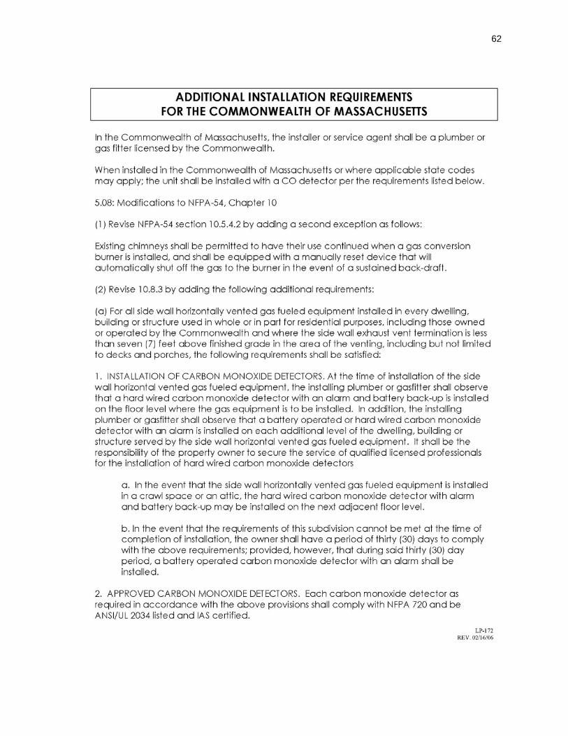
62

63

64
MAINTENANCE NOTES

65
HTP CUSTOMER INSTALLATION RECORD FORM The following form should be completed by the installer for you to keep as a record of the installation in case of a warranty claim. After reading the important notes at the bottom of the page, please also sign this document. Customer’s Name:
Installation Address:
Date of Installation:
Installer’s Code/Name:
Product Serial Number(s):
Comments:
Installer’s Phone Number:
Signed by Installer:
Signed by Customer:
IMPORTANT: Customer: Please only sign after the installer has reviewed the installation, safety, proper operation and maintenance of the system. In the case that the system has any problems, please call the installer. If you are unable to make contact, please contact your HTP Sales Representative. Distributor/Dealer: Please insert contact details.
LP- 325 REV. 9.2.2010