Embed Size (px)
Citation preview
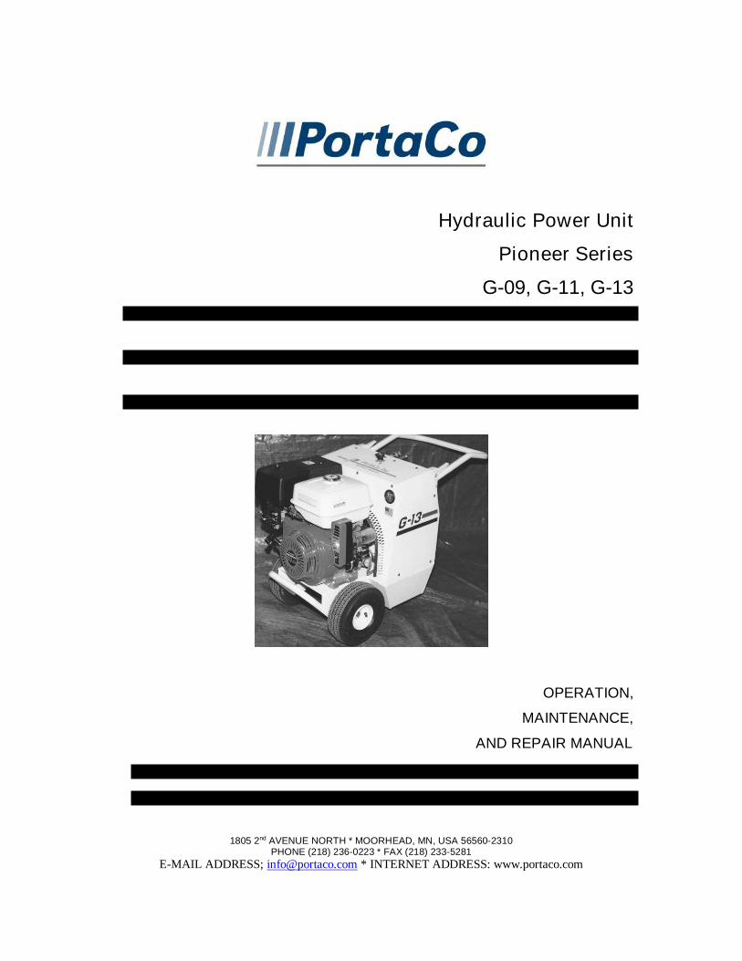
Hydraulic Power Unit
Pioneer Series
G-09, G-11, G-13
OPERATION,
MAINTENANCE,
AND REPAIR MANUAL
1805 2nd AVENUE NORTH * MOORHEAD, MN, USA 56560-2310PHONE (218) 236-0223 * FAX (218) 233-5281
E-MAIL ADDRESS; [email protected] * INTERNET ADDRESS: www.portaco.com

2
TABLE OF CONTENTS
1.0 Introduction1.1 General Information1.2 Features1.3 Options1.4 Safety Summary1.5 General Safety Precautions1.6 Warning and Caution Statements1.7 Training Requirements
2.0 Installation Instructions2.1 Unpacking Instructions2.2 Engine Preparation2.3 Hydraulic Power Unit Preparation2.4 Testing2.5 Adjustments2.6 Hose Requirements2.7 Tool Connecting Procedures2.8 Work Area Safety Precautions
3.0 Operating Instructions3.1 Description of Power Unit3.2 Controls and Graphics3.3 Before Start Up3.4 Positioning the Power Unit3.5 Startup3.6 Shutdown3.7 Cold Weather Operation3.8 Storage Preparation
4.0 Maintenance Instructions4.1 Routine Servicing and InspectionSchedule4.2 Assembly View and Parts List4.3 Hydraulic Fluids and enginemaintenance4.4 Trouble Shooting4.5 Technical Specifications
3
1.0 INTRODUCTION
1.1 General Information
This manual presents installation,operation, and maintenance informationfor the Pioneer G-09, G-11, G-13 seriesPortaCo Hydraulic Power Units. ModelG-09S06-52-W, G-11S07-52-W,G-13S08-52-W.
PortaCo, Inc. reserves the right to makechanges at anytime without notice andwithout incurring any obligation.
The Pioneer Power Unit is designed toprovide hydraulic flow and pressure foroperation of H.T.M.A. type I, II,hydraulic tools.
The G-09506-52-W provides 5.9 gpm(22.4 Liters) at 1800 psi (125 BAR) tooperate type I hydraulic tools. TheG-11507-52-W provides 7gpm(26 Liters) at 2000 psi (148 BAR) tooperate type I hydraulic tools. TheG-13508-52-W provides 8 gpm (30.3Liters) at 2000 psi (148 BAR) to operatetype II hydraulic tools.
For the G-11, and G-13 PortaCo powerunits produce a maximum pressure of148 BAR (2150 PSI). The G-09 powerunit produces a maximum pressure of135 BAR (1950 PSI).
The power units are all equipped withair-to-oil coolers with suction fanmounted to the power shaft on theengine.
The fuel and hydraulic systems are self-contained with the required reservoir,filtration and level indicators.
CAUTION: DO NOT USE CLOSED-CENTER TOOLS WITH THISPOWER UNIT
1.2 Features
The main features of the PortaCoPioneer G-09, G-11, and G-13 pioneerseries are as follows:
Standard unit is a wheeled style frame:Length 67.3 cm (26.5 in.)Width 50.8 cm (20 in.)Height 69.8 cm (27.5 in.)Weight 64.9 kg (143 lbs.)
Upper ambient operatingTemperature 43 C (110° F)Lower ambient operatingTemperature -28°C (-20 F)
The Pioneer series comes with either aBriggs & Stratton or a Honda Engine.
See the engine manual supplied with thepower unit for recommended fuel andfuel restrictions.
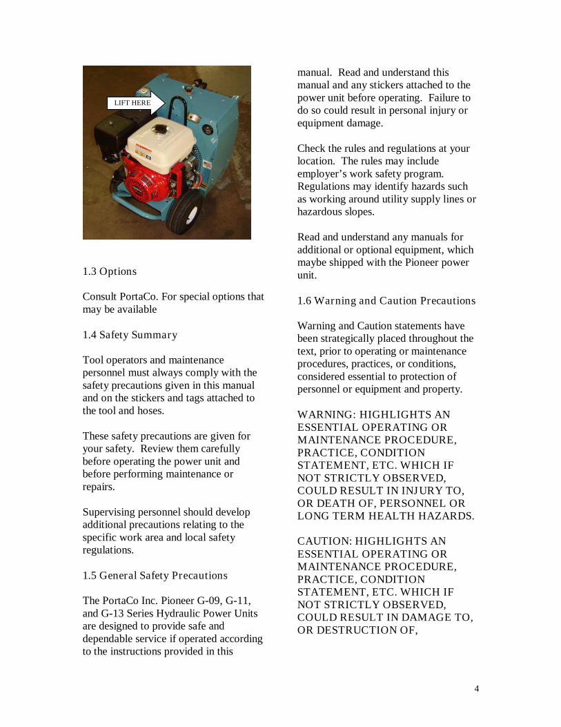
The standard wheeled Pioneer seriespower unit is equipped with collapsiblehandle, which locks in place with alatch, (see fig. 1.2A) and a lifting pointfor a crane hook. (Fig. 1.2B)
(Fig. 1.2A)
4
1.3 Options
Consult PortaCo. For special options thatmay be available
1.4 Safety Summary
Tool operators and maintenancepersonnel must always comply with thesafety precautions given in this manualand on the stickers and tags attached tothe tool and hoses.
These safety precautions are given foryour safety. Review them carefullybefore operating the power unit andbefore performing maintenance orrepairs.
Supervising personnel should developadditional precautions relating to thespecific work area and local safetyregulations.
1.5 General Safety Precautions
The PortaCo Inc. Pioneer G-09, G-11,and G-13 Series Hydraulic Power Unitsare designed to provide safe anddependable service if operated accordingto the instructions provided in this
manual. Read and understand thismanual and any stickers attached to thepower unit before operating. Failure todo so could result in personal injury orequipment damage.
Check the rules and regulations at yourlocation. The rules may includeemployer’s work safety program.Regulations may identify hazards suchas working around utility supply lines orhazardous slopes.
Read and understand any manuals foradditional or optional equipment, whichmaybe shipped with the Pioneer powerunit.
1.6 Warning and Caution Precautions
Warning and Caution statements havebeen strategically placed throughout thetext, prior to operating or maintenanceprocedures, practices, or conditions,considered essential to protection ofpersonnel or equipment and property.
WARNING: HIGHLIGHTS ANESSENTIAL OPERATING ORMAINTENANCE PROCEDURE,PRACTICE, CONDITIONSTATEMENT, ETC. WHICH IFNOT STRICTLY OBSERVED,COULD RESULT IN INJURY TO,OR DEATH OF, PERSONNEL ORLONG TERM HEALTH HAZARDS.
CAUTION: HIGHLIGHTS ANESSENTIAL OPERATING ORMAINTENANCE PROCEDURE,PRACTICE, CONDITIONSTATEMENT, ETC. WHICH IFNOT STRICTLY OBSERVED,COULD RESULT IN DAMAGE TO,OR DESTRUCTION OF,
LIFT HERE
5
EQUIPMENT OR LOSS OFMISSION EFFECTIVENESS.
1.7 Training Requirements
Operator training should consist ofinformation found in this manual for thehydraulic power unit. In addition theoperator must receive instructions boththrough demonstrations and verballywith the tools or applications in whichthe power unit is going to be used. Thenew operator must start in an areawithout bystanders and use all controlsuntil able to fully operate the power unitunder the conditions for the work area.
2.0 INSTALLATIONINSTRUCTIONS
2.1 Unpacking Instructions
Upon receiving your Pioneer hydraulicpower unit, promptly remove it from theshipping container. Always keep topside of container up. Inspect unit fordamage which may have incurred duringshipping and report it to carrier forclaim.
2.2 Engine Preparation
CAUTION: READ ANDUNDERSTAND ENGINE MANUALWHICH IS PROVIDED INADDITION TO THE PORTACOMANUAL BEFORE STARTINGTHE POWER UNIT.
CAUTION: ALWAYS CHECKENGINE OIL BEFORE STARTINGPOWER UNIT.
Make sure engine oil is at the “FULL”mark on the dipstick.
See engine manual for recommended oiland checking procedures.
NOTE: clean up oil and fuel spillsimmediately. Do not over fill fluids.
2.3 Hydraulic Power Unit Preparation
CAUTION: DO NOT OPERATEPOWER UNIT WITH BELOWRECOMMENDED HYDRAULICOIL LEVEL. PUMP DAMAMAGEMAY ACURE.
Check hydraulic fluid level by looking atsight pipe located on top of the oilreservoir. Proper oil level is indicatedwhen the center section of the sight pipeis dark. To add hydraulic fluid removefilter cap on top of reservoir, replacewhen finished. Reservoir capacity is18.9 LTR (5.0 gal) do not overfill fluids,clean up oil spills immediately. Onlyhydraulic fluids meeting thespecifications located below arerecommended for use with PortaCohydraulic power units.
(Fig. 2.3A)
Viscosity (Fluid Thickness)METRIC U.S.A.
10 C 95 Centistokes 50 F 450 SSU Max38 C 27-42 C.S. 100 F 130-200 SSU60 C 16.5 C.S, Min. 140 F 85 SSU Min.
Pour Point -10 F/23 C Minimum (for cold startup)
Viscosity Index (ASTM D 2220) 140 Minimum
Demulsibility (ASTM D-1401) 30 Minutes Maximum
Flash Point (ASTM D-92) 340 F/171 C Minimum
Rust Inhibition (ASTM D-665 A & B) Pass
Oxidation (ASTM D943) 1000 Hours Minimum
Pump Wear Test (ASTM D2882) 60 mg Maximum
6
The following fluids work well over awide temperature range at startup, allowmoisture to settle out, and resistbiological growth likely in cooloperating hydraulic circuits. Thesefluids are recommended by PortaCo, Inc.Other fluids that meet or exceed thespecifications of these fluids may also beused.
Type Hydraulic fluidChevron “Clarity” AW 15032Exxon “Univis” J 32Mobil D.T.E. 13 MGulf “Harmony” AW-HVI-150-32Shell “Tellus T” 32Texaco “Rando” HDZ 32Union “Unax” AW-WR-32Amsoil AWH 15032Sunvis Low Pour H/032-product code 19300
Fill the fuel reservoir to a level justbelow the bottom of the filter tube.Always use clean gasoline asrecommended in the engine manual. Donot overfill fluids, clean up oil and fuelspills immediately.
2.4 Testing
All power units are tested at the factoryand their flows and pressures arerecorded on the test report, which isshipped with the power unit. Testing ofthe power unit is not required unless it isdamaged during shipping.
Always perform “before startupprocedures” found in section 3.3 beforetesting. PortaCo Hydraulic Tester, PartNumber T-00016-XX-0 is recommendedfor all tests.
a. Set the hydraulic circuit to “OFF.”b. Connect hydraulic hoses to the
power unit. Connect the PortaCoHydraulic Tester to the opposite end
of the hoses. Make sure flowdirection is correct.
c. Start the engine and allow thehydraulic fluid to warm to about100° F/38 C°.
d. Open the tester restrictor valve (fullyopen.) This represents minimumload.
e. Set the flow control to “ON” and setengine throttle for maximum speed.
f. Check the flow rate and pressure onthe tester gauges. The back pressurereading should be under 17.3 bar(250 PSI). The flow readings shouldmatch those listed in section 1.1General Information of this manual.
g. With engine throttle set at maximumspeed slowly close the restrictorvalve on the tester while observingthe flow pressure gauges.
h. As the hydraulic system relief valvebegins to crack (open) and bypassfluid through the valve, the flow ratewill begin to drop. At this time, thepressure in the system should bebetween 145-155 BAR (2100-2250PSI).
i. If the pressure is not as specified, thehydraulic circuit relief valve must beadjusted or replaced. (See section4.2 for procedure.)
- If the flow rate drops below thespecified range, the pump orcontrol valve may be worn.
- If the flow remains constant, butpressure does not increase, therelief valve may be defective.
2.5 Adjustments
The engine RPM’s and the hydraulicsystem flow and pressure relief are set atthe factory and must not be readjusted.
7
DO NOT change governor setting ortamper with governor components,which may increase the governed enginespeed.
WARNING: OPERATING THEPOWER UNIT AT EXCESSIVESPEEDS INCREASE THE DANGEROF PERSONAL INJURY.
2.6 Hose Requirements
The Pioneer series are easily movedclose to the job site. It is not oftennecessary or advisable to use long hoses.All hoses must have an oil resistant innersurface and an abrasion resistant outersurface. Each hose must have male pipeends for most application. Longer hosescan be used when necessary, but canaffect the operation of the tool due toresistance in the hose.
If small diameter or long hoses are used,or if restrictive fittings are connected tothe supply and return ports, the pressurerequired, to push the fluid through thesystem and back to the tank will behigher. This will reduce tool power.
The pressure and return hose areconnected to the control block. A½-inch male pipe hose end can beconnected, to H.T.M.A. flat-nosedquick-disconnect couplings (availablethrough PortaCo, Inc).
The left port of the control block is thepressure (oil out) fitting. A maleH.T.M.A. quick-disconnect coupling(without lock ring) must be connected tothis port.
Two hoses are required to complete thecircuit, each hose should have a malecoupler on one end and a female coupleron the opposite. See diagram on page 8for hose routing.
*Important – Oil should always flowfrom the male coupler through thefemale coupler.
The right port is the return port. Afemale H.T.M.A. quick-disconnectcoupling should be connected to thisport.
NOTE: The pressure increase inuncoupled hoses left in the sun maymake them difficult to connect. Whenpossible after use, connect the free endsof the operating hoses together.
HOSE TYPES
Hydraulic hose types authorized for useby PortaCo, Inc. are as follows:
1. Labeled and certified non-conductive2. Wire braided (conductive)3. Fabric braided (not certified or labeled non-
conductive)
Hose 1: Listed above is the only hose authorizedfor use near electrical conductors.
Hoses 2 and 3: Listed above are conductive andmust never be used near electrical conductors.
HOSE PRESSURE RATING
The rated working pressure of thehydraulic hose must be at least 175 bar(2500 PSI.)
8
HYDRAULIC HOSE RECOMMENDATIONSTable 2.6A
FLOW PER CIRCUIT LENGTH EACH HOSE USE INSIDE DIAMETER SAE SPEC HOSE(WIRE BRAID)
SAE SPECHOSE (FIBER
BRAID)GPM LPM FEET METERS INCH MM5 to 8 19 to 30 To 50 To 15 Both 1/2 13 SAE 100R1-8 100R7-85 to 8 19 to 30 51-100 15 to 30 Both 5/8 16 SAE 100R2-10 SAE 100R8-105 to 8 19 to 30 100-300 30 to 90 Pressure
Return5/83/4
1619
SAE 100R2-10SAE 100R1-12
SAE 100R8-10SAE 100R7-12
9 to 12 34 to 45 To 50 To 15 Both 5/8 16 SAE 100R2-10 SAE 100R8-10
9 to 12 34 to 45 51-100 15 to 30 PressureReturn
5/83/4
1619
SAE 100R2-10SAE 100R3-12
SAE 100R8-10SAE 100R7-12
9 to 12 34 to 45 100-200 30 to 60 PressureReturn
3/41
1925.4
SAE 100R2-12SAE 100R1-16
SAE 100R8-12SAE 100R7-16
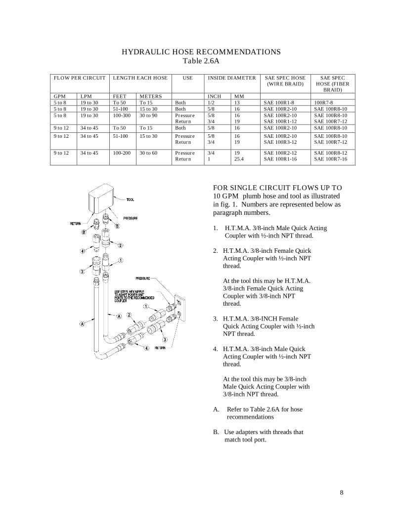
FOR SINGLE CIRCUIT FLOWS UP TO10 GPM plumb hose and tool as illustratedin fig. 1. Numbers are represented below asparagraph numbers.
1. H.T.M.A. 3/8-inch Male Quick ActingCoupler with ½-inch NPT thread.
2. H.T.M.A. 3/8-inch Female QuickActing Coupler with ½-inch NPTthread.
At the tool this may be H.T.M.A.3/8-inch Female Quick ActingCoupler with 3/8-inch NPTthread.
3. H.T.M.A. 3/8-INCH FemaleQuick Acting Coupler with ½-inchNPT thread.
4. H.T.M.A. 3/8-inch Male QuickActing Coupler with ½-inch NPTthread.
At the tool this may be 3/8-inchMale Quick Acting Coupler with3/8-inch NPT thread.
A. Refer to Table 2.6A for hoserecommendations
B. Use adapters with threads thatmatch tool port.
9
2.7 Tool Connecting Procedures.
Inspect hose for cuts, crushing, leaks, orabrasion which maybe a safety hazard orreduce fluid flows.
WARNING: DO NOTATTEMPT TO LOCATEHYDRAULIC LEAKS BY FEELINGAROUND HOSES AND FITTINGWITH HANDS. “PIN-HOLE” LEAKSCAN PENETRATE THE SKIN.
Stop the engine before connecting thetool and, or hoses to the off power unit,and when switching hoses or tools. Turnthe hydraulic on/off valve to the offposition before starting the engine.Make sure all hoses are connected forcorrect flow direction to and from thetool being used. When routing hose inthe work area, position them wherepersonnel will not be at risk of trippingover them or where vehicles can runover the hoses. Do not lay hose oversharp projects.
WARNING: PRESSURIZED FLUIDESCAPING FROM A DAMAGEDHOSE CAN PENETRATE THESKIN AND BE INJECTED IN THEBODY CAUSING INJURY ORDEATH.
CAUTION: DO NOT PULL ON HOSESTO DRAG POWER UNIT.
2.8 Work Area Safety Precautions
- Never operate the power unit in aclosed space. Inhalation of
engine exhaust can be fatal.
- Keep clear of hot exhaust.
- Do not use PortaCo hydraulicpower units in potentially explosiveatmospheres such as nearwastewater drains or landfill sites.
- Do not operate if flammable gasesor vapors are present.
- Keep the power unit at least 1meter(3.3 ft) away from buildings, obstructions,and flammable objects. Do not aim engineexhaust at materials that could catch fire.
- Allow the engine to cool beforestoring the power unit in anenclosed space.
- PortaCo hydraulic power units mustnot be located below overheadgantries, power lines, or walkwayswhere there might be a risk offalling objects.
- Provide ambient light intensity of200 Lux for working indoors oroutdoors particularly if working atnight.
- Always wear appropriate safetyequipment such as goggles, earprotection, and foot protections.
- Operate only tools which fit intothe specifications prescribed insection 1.1 of this manual.
- Do not stand on power unit.
10
3.0 OPERATING INSTRUCTIONS
3.1 Description of Power Unit
The PortaCo Pioneer seriesHydraulic Power Unit has been designedfor the purpose of supplying hydraulicfluid under pressure to power hydraulichand tools. The standard engine is aHonda 9 hp, 11 hp, or 13 hp. dependingon the model of power unit purchased.See section 1.2 features of this manualfor specifications. See the technicalmanuals supplied by the enginemanufacture included with this powerunit for detailed technical specifications.
PortaCo Hydraulic Power Units havebeen designed for use indoors andoutdoors. PortaCo power units shouldnot be operated under wet conditions, orat ambient operating temperatures,outside the recommended temperaturerange of -28° C to 43° C. (-20° F to110° F).
CAUTION: DO NOT USE CLOSED-CENTER TOOLS WITH THISPOWER UNIT.
During operation, the engine may bog,run at lower rpm, when under load. Asthe tool being used is loaded, meets withincrease resistance, the pressure requiredto operate the tool increases. Theincreased pressure adds load to the pumpwhich loads the engine, there byreducing the RPMS. As a result, theflow will drop as pressure increases.The hydraulic system has a pressurelimiter set at 148 BAR (2150 PSI) whichdiverts the flow back to the tank until thepressure drops below 148 BAR (2150PSI.)
Tools with higher flow and, or pressurerequirements will not operate at their fullpotential if used with the PortaCoHydraulic Power Unit. Tools with lowerflow and or pressure requirements maybe damaged if used with this power unit.
The engine throttle and the hydraulicsystem relief value are preset at thefactory and must not be altered for anyreason without consulting PortaCo Inc.Any alterations approved by PortaCoInc., can only be preformed by personnelqualified to maintain hydraulic systems.
Tools which are commonly used withPortaCo’s Pioneer series Hydraulicpower unit are as follows:
Impact WrenchesImpact DrillsPicksHandheld grindersBreakersTampersHand Held SawsHand Held Pruners
Do not use the Pioneer series power unitwith close-center tools, tools which donot allow the oil to return to the powerunit when not activated. Do not use injacking operations. Do not use toactivate cylinders without an inlineopen-center control system. Do notoperate without a return oil hose.
If there are any doubts weather your toolcan be used with the Pioneer series unitplease contact the service department atPortaCo Inc. (218-236-0223) for advice.PortaCo Inc. accepts NO responsibilityfor machines that are used for anypurpose other than the intended purposeas specified in the operating instructionsor approved directly by PortaCo Inc.
11
3.2 Controls and Graphics
WARNING: FAILURE TOFOLLOW THE PROCEDURESLISTED IN THE ENGINE’SOWNER’S MANUAL COULDRESULT IN PERSONAL INJURYOR EQUIPMENT DAMAGE.
Refer to the engine owner’s manual forexplanation of controls and symbolslocated on the engine.
The following decals are placed on thepower unit to aid in its operation andmaintenance. The operator should locateand understand them before using thispower unit.
A caution fan decal advises operators ofan area, which contains a potentialhazard if guards are not properly inposition. (Fig. 3.2A)
(Fig. 3.2A)
The hydraulic oil reservoir is markedwith a hydraulic oil decal (Fig. 3.2B)and there is a hydraulic oil drain decalindicating the tank’s drain plug (Fig.3.2C)
(Fig. 3.2B)
(Fig 3.2C)
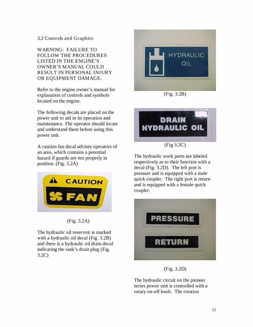
The hydraulic work ports are labeledrespectively as to their function with adecal (Fig. 3.2D). The left port ispressure and is equipped with a malequick coupler. The right port is returnand is equipped with a female quickcoupler.
(Fig. 3.2D)
The hydraulic circuit on the pioneerseries power unit is controlled with arotary on-off knob. The rotation
12
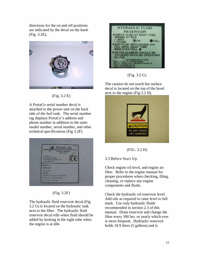
directions for the on and off positionsare indicated by the decal on the knob(Fig. 3.2E).
(Fig. 3.2 E)
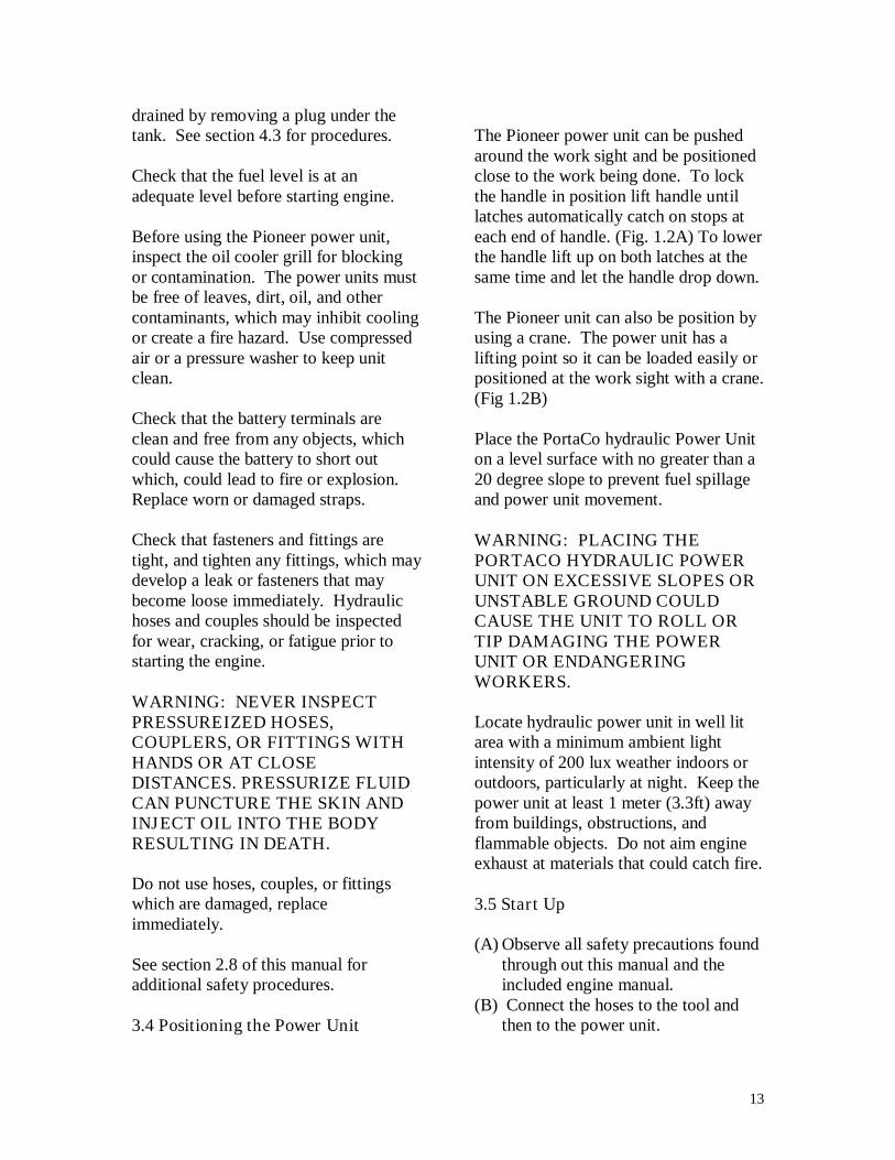
A PortaCo serial number decal isattached to the power unit on the backside of the fuel tank. The serial numbertag displays PortaCo’s address andphone number in addition to the unitsmodel number, serial number, and othertechnical specifications (Fig 3.2F).
(Fig. 3.2F)
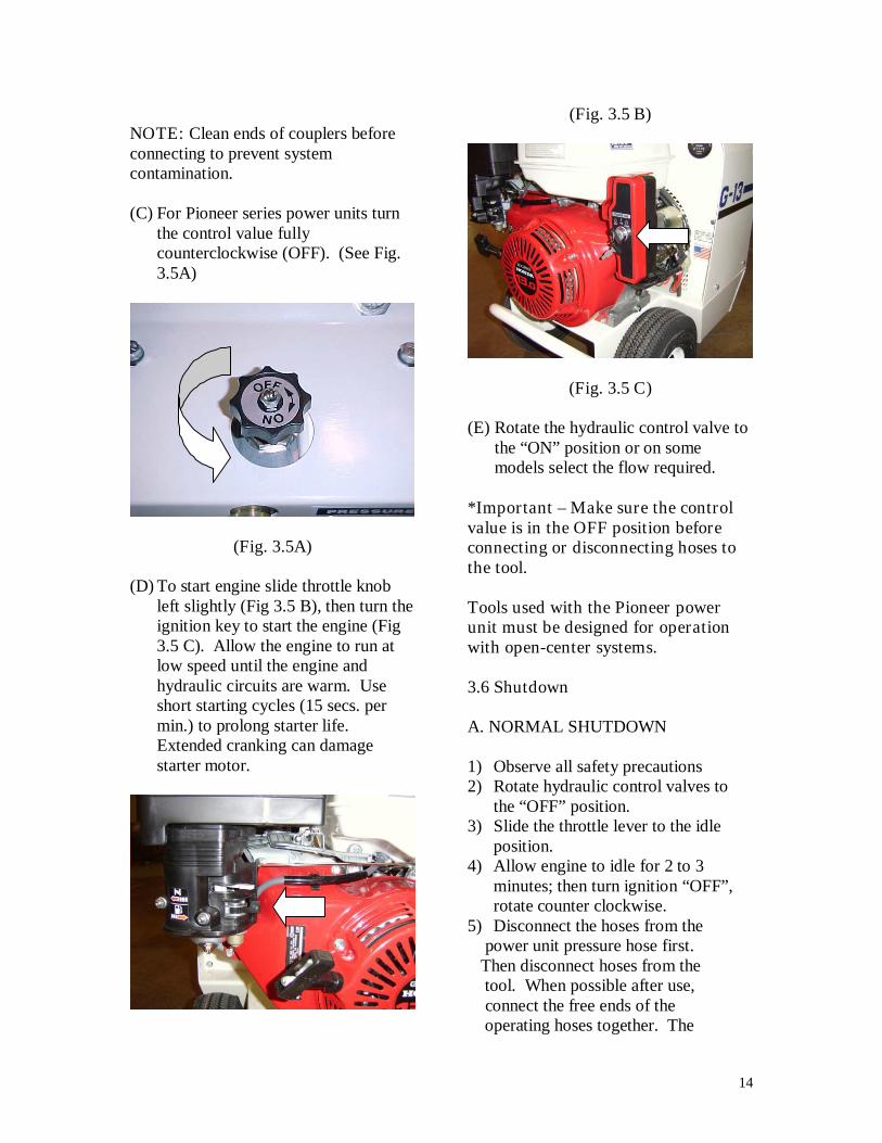
The hydraulic fluid reservoir decal (Fig3.2 G) is located on the hydraulic tanknext to the filter. The hydraulic fluidreservoir decal tells when fluid should beadded by looking in the sight tube whenthe engine is at idle.
(Fig. 3.2 G)
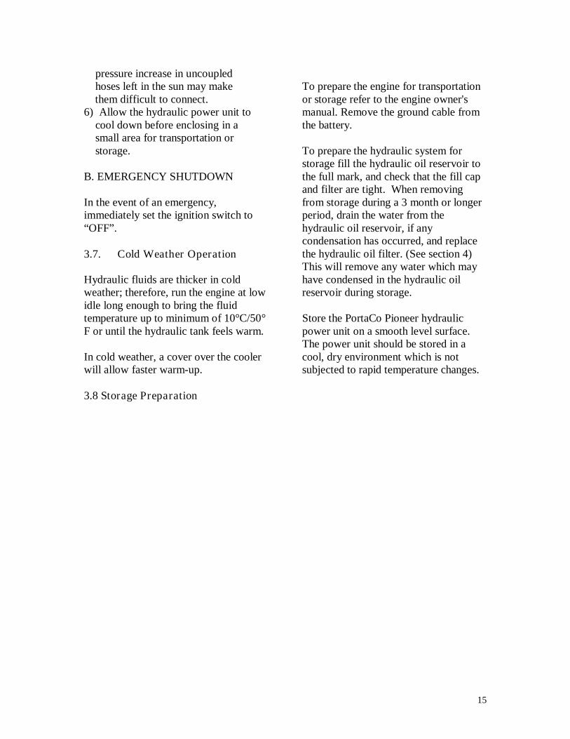
The caution do not touch hot surfacedecal is located on the top of the hoodnext to the engine (Fig 3.2 H).
(FIG. 3.2 H)
3.3 Before Start Up
Check engine oil level, and engine airfilter. Refer to the engine manual forproper procedures when checking, filing,cleaning, or replace any enginecomponents and fluids.
Check the hydraulic oil reservoir level.Add oils as required to raise level to fullmark. Use only hydraulic fluidsrecommended in section 2.3 of thismanual. Drain reservoir and change thefilter every 300 hrs. or yearly which everis more frequent. Hydraulic reservoirholds 18.9 liters (5 gallons) and is
13
drained by removing a plug under thetank. See section 4.3 for procedures.
Check that the fuel level is at anadequate level before starting engine.
Before using the Pioneer power unit,inspect the oil cooler grill for blockingor contamination. The power units mustbe free of leaves, dirt, oil, and othercontaminants, which may inhibit coolingor create a fire hazard. Use compressedair or a pressure washer to keep unitclean.
Check that the battery terminals areclean and free from any objects, whichcould cause the battery to short outwhich, could lead to fire or explosion.Replace worn or damaged straps.
Check that fasteners and fittings aretight, and tighten any fittings, which maydevelop a leak or fasteners that maybecome loose immediately. Hydraulichoses and couples should be inspectedfor wear, cracking, or fatigue prior tostarting the engine.
WARNING: NEVER INSPECTPRESSUREIZED HOSES,COUPLERS, OR FITTINGS WITHHANDS OR AT CLOSEDISTANCES. PRESSURIZE FLUIDCAN PUNCTURE THE SKIN ANDINJECT OIL INTO THE BODYRESULTING IN DEATH.
Do not use hoses, couples, or fittingswhich are damaged, replaceimmediately.
See section 2.8 of this manual foradditional safety procedures.
3.4 Positioning the Power Unit
The Pioneer power unit can be pushedaround the work sight and be positionedclose to the work being done. To lockthe handle in position lift handle untillatches automatically catch on stops ateach end of handle. (Fig. 1.2A) To lowerthe handle lift up on both latches at thesame time and let the handle drop down.
The Pioneer unit can also be position byusing a crane. The power unit has alifting point so it can be loaded easily orpositioned at the work sight with a crane.(Fig 1.2B)
Place the PortaCo hydraulic Power Uniton a level surface with no greater than a20 degree slope to prevent fuel spillageand power unit movement.
WARNING: PLACING THEPORTACO HYDRAULIC POWERUNIT ON EXCESSIVE SLOPES ORUNSTABLE GROUND COULDCAUSE THE UNIT TO ROLL ORTIP DAMAGING THE POWERUNIT OR ENDANGERINGWORKERS.
Locate hydraulic power unit in well litarea with a minimum ambient lightintensity of 200 lux weather indoors oroutdoors, particularly at night. Keep thepower unit at least 1 meter (3.3ft) awayfrom buildings, obstructions, andflammable objects. Do not aim engineexhaust at materials that could catch fire.
3.5 Start Up
(A) Observe all safety precautions foundthrough out this manual and theincluded engine manual.
(B) Connect the hoses to the tool andthen to the power unit.
14
NOTE: Clean ends of couplers beforeconnecting to prevent systemcontamination.
(C) For Pioneer series power units turnthe control value fullycounterclockwise (OFF). (See Fig.3.5A)
(Fig. 3.5A)
(D) To start engine slide throttle knobleft slightly (Fig 3.5 B), then turn theignition key to start the engine (Fig3.5 C). Allow the engine to run atlow speed until the engine andhydraulic circuits are warm. Useshort starting cycles (15 secs. permin.) to prolong starter life.Extended cranking can damagestarter motor.
(Fig. 3.5 B)
(Fig. 3.5 C)
(E) Rotate the hydraulic control valve tothe “ON” position or on somemodels select the flow required.
*Important – Make sure the controlvalue is in the OFF position beforeconnecting or disconnecting hoses tothe tool.
Tools used with the Pioneer powerunit must be designed for operationwith open-center systems.
3.6 Shutdown
A. NORMAL SHUTDOWN
1) Observe all safety precautions2) Rotate hydraulic control valves to
the “OFF” position.3) Slide the throttle lever to the idle
position.4) Allow engine to idle for 2 to 3
minutes; then turn ignition “OFF”,rotate counter clockwise.
5) Disconnect the hoses from thepower unit pressure hose first.
Then disconnect hoses from thetool. When possible after use,connect the free ends of theoperating hoses together. The
15
pressure increase in uncoupledhoses left in the sun may makethem difficult to connect.
6) Allow the hydraulic power unit tocool down before enclosing in asmall area for transportation orstorage.
B. EMERGENCY SHUTDOWN
In the event of an emergency,immediately set the ignition switch to“OFF”.
3.7. Cold Weather Operation
Hydraulic fluids are thicker in coldweather; therefore, run the engine at lowidle long enough to bring the fluidtemperature up to minimum of 10°C/50°F or until the hydraulic tank feels warm.
In cold weather, a cover over the coolerwill allow faster warm-up.
3.8 Storage Preparation
To prepare the engine for transportationor storage refer to the engine owner'smanual. Remove the ground cable fromthe battery.
To prepare the hydraulic system forstorage fill the hydraulic oil reservoir tothe full mark, and check that the fill capand filter are tight. When removingfrom storage during a 3 month or longerperiod, drain the water from thehydraulic oil reservoir, if anycondensation has occurred, and replacethe hydraulic oil filter. (See section 4)This will remove any water which mayhave condensed in the hydraulic oilreservoir during storage.
Store the PortaCo Pioneer hydraulicpower unit on a smooth level surface.The power unit should be stored in acool, dry environment which is notsubjected to rapid temperature changes.
16
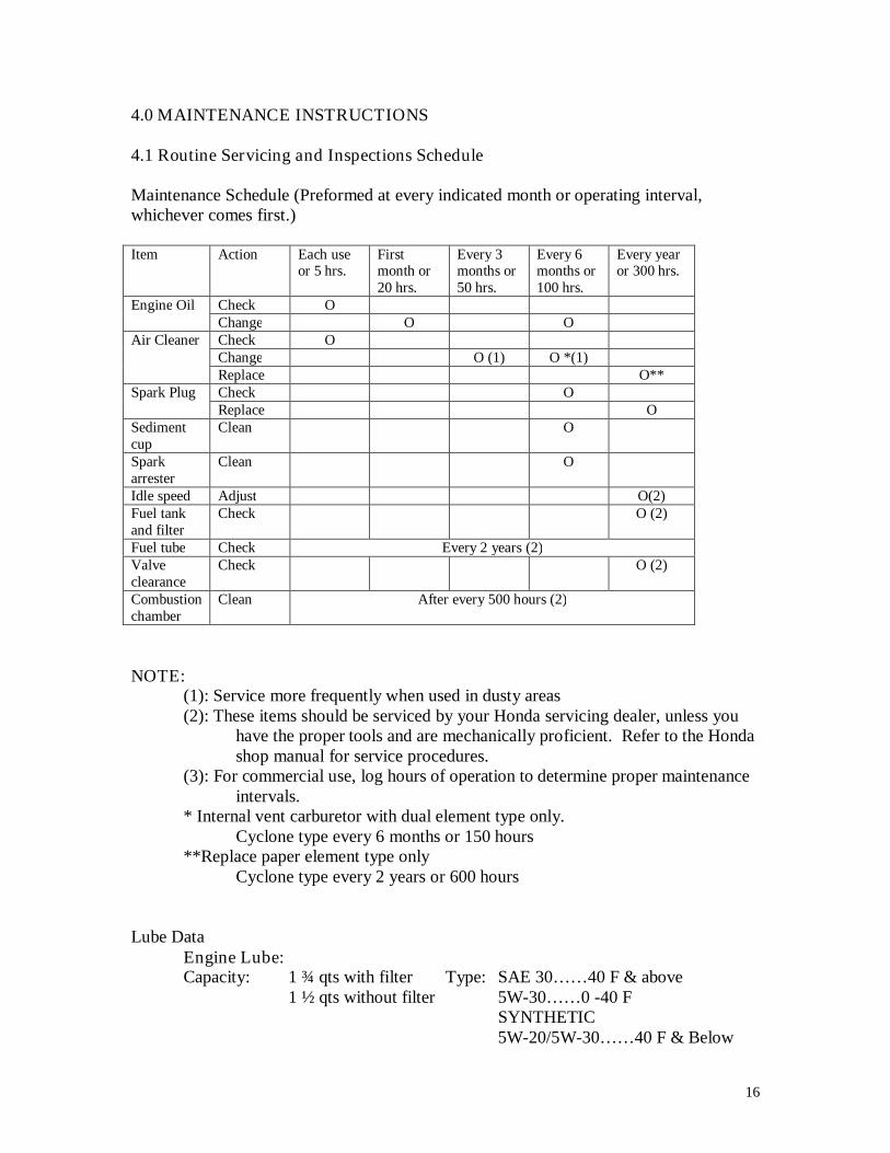
4.0 MAINTENANCE INSTRUCTIONS
4.1 Routine Servicing and Inspections Schedule
Maintenance Schedule (Preformed at every indicated month or operating interval,whichever comes first.)
Item Action Each useor 5 hrs.
Firstmonth or20 hrs.
Every 3months or50 hrs.
Every 6months or100 hrs.
Every yearor 300 hrs.
Engine Oil Check OChange O O
Air Cleaner Check OChange O (1) O *(1)Replace O**
Spark Plug Check OReplace O
Sedimentcup
Clean O
Sparkarrester
Clean O
Idle speed Adjust O(2)Fuel tankand filter
Check O (2)
Fuel tube Check Every 2 years (2)Valveclearance
Check O (2)
Combustionchamber
Clean After every 500 hours (2)
NOTE:(1): Service more frequently when used in dusty areas(2): These items should be serviced by your Honda servicing dealer, unless you
have the proper tools and are mechanically proficient. Refer to the Hondashop manual for service procedures.
(3): For commercial use, log hours of operation to determine proper maintenanceintervals.
* Internal vent carburetor with dual element type only.Cyclone type every 6 months or 150 hours
**Replace paper element type onlyCyclone type every 2 years or 600 hours
Lube DataEngine Lube:Capacity: 1 ¾ qts with filter Type: SAE 30……40 F & above
1 ½ qts without filter 5W-30……0 -40 FSYNTHETIC5W-20/5W-30……40 F & Below
17
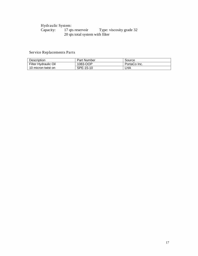
Hydraulic System:Capacity: 17 qts reservoir Type: viscosity grade 32
20 qts total system with filter
Service Replacements Parts
Description Part Number SourceFilter Hydraulic Oil10 micron twist on
1083-OOP PortaCo Inc.SPE-15-10 LHA
18
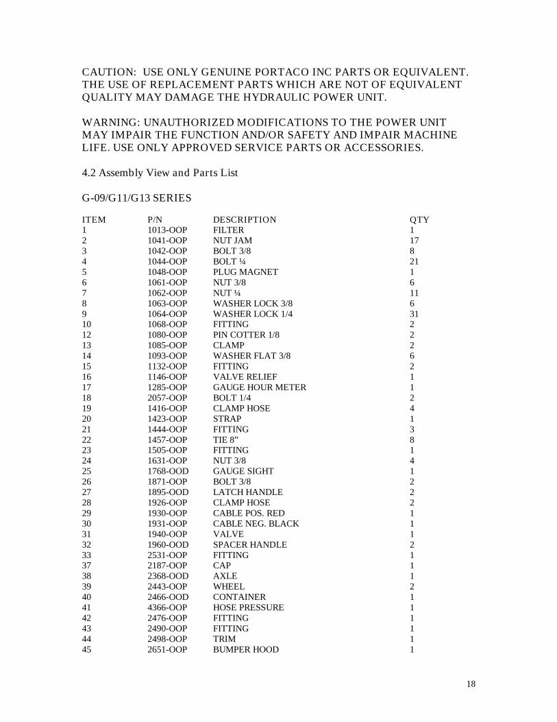
CAUTION: USE ONLY GENUINE PORTACO INC PARTS OR EQUIVALENT.THE USE OF REPLACEMENT PARTS WHICH ARE NOT OF EQUIVALENTQUALITY MAY DAMAGE THE HYDRAULIC POWER UNIT.
WARNING: UNAUTHORIZED MODIFICATIONS TO THE POWER UNITMAY IMPAIR THE FUNCTION AND/OR SAFETY AND IMPAIR MACHINELIFE. USE ONLY APPROVED SERVICE PARTS OR ACCESSORIES.
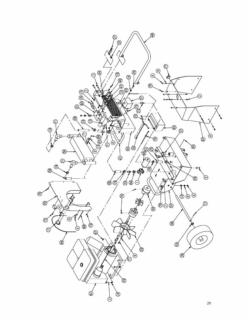
4.2 Assembly View and Parts List
G-09/G11/G13 SERIES
ITEM P/N DESCRIPTION QTY1 1013-OOP FILTER 12 1041-OOP NUT JAM 173 1042-OOP BOLT 3/8 84 1044-OOP BOLT ¼ 215 1048-OOP PLUG MAGNET 16 1061-OOP NUT 3/8 67 1062-OOP NUT ¼ 118 1063-OOP WASHER LOCK 3/8 69 1064-OOP WASHER LOCK 1/4 3110 1068-OOP FITTING 212 1080-OOP PIN COTTER 1/8 213 1085-OOP CLAMP 214 1093-OOP WASHER FLAT 3/8 615 1132-OOP FITTING 216 1146-OOP VALVE RELIEF 117 1285-OOP GAUGE HOUR METER 118 2057-OOP BOLT 1/4 219 1416-OOP CLAMP HOSE 420 1423-OOP STRAP 121 1444-OOP FITTING 322 1457-OOP TIE 8” 823 1505-OOP FITTING 124 1631-OOP NUT 3/8 425 1768-OOD GAUGE SIGHT 126 1871-OOP BOLT 3/8 227 1895-OOD LATCH HANDLE 228 1926-OOP CLAMP HOSE 229 1930-OOP CABLE POS. RED 130 1931-OOP CABLE NEG. BLACK 131 1940-OOP VALVE 132 1960-OOD SPACER HANDLE 233 2531-OOP FITTING 137 2187-OOP CAP 138 2368-OOD AXLE 139 2443-OOP WHEEL 240 2466-OOD CONTAINER 141 4366-OOP HOSE PRESSURE 142 2476-OOP FITTING 143 2490-OOP FITTING 144 2498-OOP TRIM 145 2651-OOP BUMPER HOOD 1
19
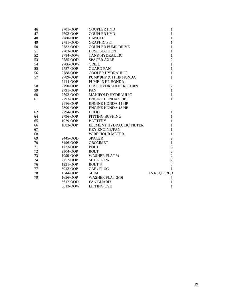
46 2701-OOP COUPLER HYD 147 2702-OOP COUPLER HYD 148 2780-OOP HANDLE 149 2781-OOD GRAPHIC SET 150 2782-OOD COUPLER PUMP DRIVE 151 2783-OOP HOSE SUCTION 152 2784-OOW TANK HYDRAULIC 153 2785-OOD SPACER AXLE 254 2786-OOW GRILL 155 2787-OOP GUARD FAN 156 2788-OOP COOLER HYDRAULIC 157 2789-OOP PUMP 9HP & 11 HP HONDA 1
2414-OOP PUMP 13 HP HONDA58 2790-OOP HOSE HYDRAULIC RETURN 259 2791-OOP FAN 160 2792-OOD MANIFOLD HYDRAULIC 161 2793-OOP ENGINE HONDA 9 HP 1
2886-OOP ENGINE HONDA 11 HP2890-OOP ENGINE HONDA 13 HP
62 2794-OOW HOOD 164 2796-OOP FITTING BUSHING 165 1929-OOP BATTERY 166 1083-OOP ELEMENT HYDRAULIC FILTER 167 KEY ENGINE/FAN 168 WIRE HOUR METER 169 2445-OOD SPACER 270 3496-OOP GROMMET 171 1733-OOP BOLT 372 2304-OOP BOLT 273 1099-OOP WASHER FLAT ¼ 274 2752-OOP SET SCREW 276 1221-OOP BOLT ¼ 377 3012-OOP CAP / PLUG 178 1544-OOP SHIM AS REQUIRED79 1656-OOP WASHER FLAT 3/16 5
3612-OOD FAN GUARD 13613-OOW LIFTING EYE 1
20
21
4.3 HYDRAULIC FLUID ANDENGINE MAINTENANCE
WARNING: SHUT OFF ENGINEBEFORE DOING ANYMAINTENANCE. TO PREVENTACCIDENTAL START-UP, TURNTHE IGNITION SWITCH OFF ANDDISCONNECT THE NEGATIVECABLE FROM THE BATTERYTERMINAL.
Engine Lubrication ServicingCheck the engine oil level and changeoil and filter as required in themaintenance table section 4.1 of thismanual.
The oil level should be between the“full” and “add” marks of the dipstick.Also illustrated in the engine manual.To add oil to the engine, remove thefiller cap. Engine oil capacity is 1.8liters (1.9 quarts) when changing oilfilter.
The following oils are recommended bythe engine manufacturer:
Temperature Range Oil5° C (40° F) and above SAE 30¯18° C- (0° F) - 5° C (40° F) 5W-30
10W-305° C (40° F) and below Synthetic 5W-20
5W-30
When draining oil place a suitablecontainer under the drain plug andremove plug. Drain engine completelyand replace plug.
Engine Fuel Servicing
Replace the fuel filter every 100 hrs. oryearly. Remove the filter cartridge and
replace it. Slightly lubricate the filterseal before installation.
NOTE: See engine manual foradditional service requirements.
NOTE: Dispose of all consumable items(filters, oils….etc.) in a manner that iscompatible with the environment.PortaCo, Inc. suggests you take suchitems in a sealed container to your localservice station for reclamation. DONOT throw these items in the trash orpour them on the ground.
Hydraulic Fluid Servicing
Removing CondensationOnce a week (Less often in hot dryweather) take a small sample from thebottom of the hydraulic tank byremoving the ½” N.P.T. drain plug. Ifclear water appears, drain the tank untilclean oil starts to show. Always draintank into a suitable container. If fluid ismilky, allow unit to settle for 48 hoursbefore draining.
NOTE: Water in the fluid reduceslubrication and causes premature wear.1% water in a 140 BAR (2000 PSI)system can cause a 25% increases inwear rate.
Replace Filter and Fluid
CAUTION: ALWAYS FOLLOWANY HANDLING PRECAUTIONSPUBLISHED BY THEMANUFACTURES OF THELUBRICANTS OR HYDRAULICFLUIDS USED.
22
- Remove the drain plug on theunderside of the hydraulic tank anddrain oil into a suitable container.Let reservoir completely drain andreinstall the plug.
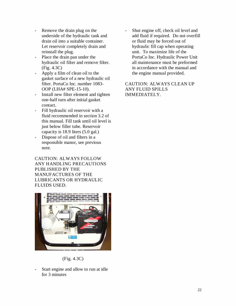
- Place the drain pan under thehydraulic oil filter and remove filter.(Fig. 4.3C)
- Apply a film of clean oil to thegasket surface of a new hydraulic oilfilter. PortaCo Inc. number 1083-OOP (LHA# SPE-15-10).
- Install new filter element and tightenone-half turn after initial gasketcontact.
- Fill hydraulic oil reservoir with afluid recommended in section 3.2 ofthis manual. Fill tank until oil level isjust below filler tube. Reservoircapacity is 18.9 liters (5.0 gal.)
- Dispose of oil and filters in aresponsible manor, see previousnote.
CAUTION: ALWAYS FOLLOWANY HANDLING PRECAUTIONSPUBLISHED BY THEMANUFACTURES OF THELUBRICANTS OR HYDRAULICFLUIDS USED.
(Fig. 4.3C)
- Start engine and allow to run at idlefor 3 minutes
- Shut engine off, check oil level andadd fluid if required. Do not overfillor fluid may be forced out ofhydraulic fill cap when operatingunit. To maximize life of thePortaCo Inc. Hydraulic Power Unitall maintenance must be preformedin accordance with the manual andthe engine manual provided.
CAUTION: ALWAYS CLEAN UPANY FLUID SPILLSIMMEDIATELY.
23
4.4 Trouble Shooting
Problem Cause RemedyEngine will not start Engine Switch “OFF” Turn engine switch “ON.”
Engine oil low Add engine oil if requiredFuel valve “OFF” Turn fuel valve “ON”Fuel level low Add fuelFuel not reachingcarburetor
Refer to engine manual for properprocedure
No spark at spark plug Refer to engine manual for properprocedure
None of the above Take the engine to an authorizeddealer that represents themanufacturer of the engine yourpower unit is equipped with.
Engine runs buthydraulic circuit willnot drive tools.
ON-OFF valve “OFF” Turn valve “ON”Tool not connected topower unit
Turn valve “OFF,” connect tool,turn valve “ON”
Hydraulic fluid reservoirlow
Check and fill as required
Damaged couplers orhoses
Check that couplers and hoses arein good condition, replace asrequired
Tool hoses incorrectlyconnected to circuit
Check that hoses connect“pressure” from power unit topressure inlet of tool, and “Return”at power unit connects to returnoutlet of tool.
Relief valve stuck open.Clear blockage (see section 4.2)replace if required.
Engine runs buthydraulic circuit willnot drive tool
Tool is defective Repair as necessary
Tool runs too hot Relief value set too low Adjust cracking pressure to 123.2bar (1800 psi)
Hoses too small Size hose as require in section 2.6Cooler blocked Clean hydraulic oil coolerTool Doesn’t meetsystem specifications
See section 1.1 for systemspecifications
Closed-center tool in use Use only open-center tools
24
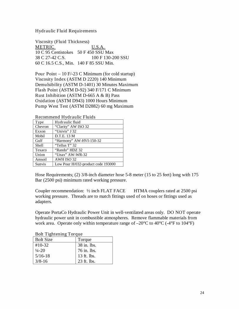
Hydraulic Fluid Requirements
Viscosity (Fluid Thickness)METRIC U.S.A.10 C 95 Centistokes 50 F 450 SSU Max38 C 27-42 C.S. 100 F 130-200 SSU60 C 16.5 C.S., Min. 140 F 85 SSU Min.
Pour Point – 10 F/-23 C Minimum (for cold startup)Viscosity Index (ASTM D 2220) 140 MinimumDemulsibility (ASTM D-1401) 30 Minutes MaximumFlash Point (ASTM D-92) 340 F/171 C MinimumRust Inhibition (ASTM D-665 A & B) PassOxidation (ASTM D943) 1000 Hours MinimumPump West Test (ASTM D2882) 60 mg Maximum
Recommend Hydraulic FluidsType Hydraulic fluidChevron “Clarity” AW ISO 32Exxon “Univis” J 32Mobil D.T.E. 13 MGulf “Harmony” AW-HVI-150-32Shell “Tellus T” 32Texaco “Rando” HDZ 32Union “Unax” AW-WR-32Amsoil AWH ISO 32Sunvis Low Pour H/032-product code 193000
Hose Requirements; (2) 3/8-inch diameter hose 5-8 meter (15 to 25 feet) long with 175Bar (2500 psi) minimum rated working pressure.
Coupler recommendation: ½ inch FLAT FACE HTMA couplers rated at 2500 psiworking pressure. Threads are to match fittings used of on hoses or fittings used asadapters.
Operate PortaCo Hydraulic Power Unit in well-ventilated areas only. DO NOT operatehydraulic power unit in combustible atmospheres. Remove flammable materials fromwork area. Operate only within temperature range of –20°C to 40°C (-4°F to 104°F)
Bolt Tightening TorqueBolt Size Torque#10-32¼-205/16-183/8-16
38 in. lbs.76 in. lbs.13 ft. lbs.23 ft. lbs.

25
SERVICE AND REPAIR NOTES


![QUEENSLAND'S PIONEER JOURNALS AND JOURNALISTS215314/s18378366_1945_3… · QUEENSLAND'S PIONEER JOURNALS AND JOURNALISTS [By ALFRED G. DAVIES] (Read at a meeting of the Historical](https://img.pdfslide.net/doc/110x75/5f06ad3f7e708231d4192f07/queenslands-pioneer-journals-and-journalists-215314s1837836619453-queenslands.jpg)