Embed Size (px)
Citation preview

Universidade de Aveiro
2013
Departamento de Engenharia Civil
PIOTR SPUŚ COST ANALYSIS OF REINFORCED CONCRETE SLABS AND COLUMNS ANÁLISE DE CUSTOS DE LAJES E PILARES EM BETÃO ARMADO


Universidade de Aveiro
2013
Departamento de Engenharia Civil
PIOTR SPUŚ COST ANALYSIS OF REINFORCED CONCRETE SLABS AND COLUMNS ANÁLISE DE CUSTOS DE LAJES E PILARES EM BETÃO ARMADO
Dissertation was presented at University of Aveiro to fulfill the requirements for the degree of Master in Civil Engineering, held under the scientific guidance of Professor Miguel Morais, Assistant Professor, Department of Civil Engineering, University of Aveiro.


Dedykuję tę pracę mamie, w podzięce za lata poświęceń.


jury
president Prof. Doutor Carlos Daniel Borges Coelho assistant professor, University o Aveiro
Dr hab. Dariusz Heim, prof. TUL associate professor, Lodz University of Technology
Prof. Doutor Miguel Nuno Lobato de Sousa Monteiro de Morais assistant professor, University o Aveiro


agradecimentos
Em primeiro lugar expresso o meu profundo agradecimento ao Professor Miguel Lobato de Sousa Monteiro de Morais pela sua disponibilidade, incentivo e compreensão durante a concretização deste trabalho. Ao meu irmão e à minha mãe pelo carinho e apoio demonstrado. À Agusia, pelas palavras de apoio quando precisei. Ao Dawid, pelo apoio nos maus momentos. Aos amigos, Márcia e André, pela sua ajuda e sugestões com este trabalho. A todos… Muito Obrigado.


podziękowania
W pierwszej kolejności pragnę podziękować mojemu promotorowi doktorowi Miguel Lobato de Sousa Monteiro de Morais za dyspozycyjność, cierpliwość i zrozumienie. Profesorowi Dariuszowi Heimowi za umożliwienie mi wyjazdu do Portugalii. Mojemu bratu i mojej mamie za troskę i wsparcie. Agusi, której zawdzięczam bardzo dużo, za okazaną bezinteresowną pomoc i bycie wzorem pracowitości. Dawidowi za wysłuchanie, gdy tego potrzebowałem. Moim kolegom z wydziału, Marcia i André, za zainteresowanie i praktyczne wskazówki. Wszystkim, ogromnie dziękuję.


keywords
rainforced concrete, design, safety check, ultimate limit states, cost analysis, flat slabs, reinforced concrete columns
abstract
The construction industry is increasingly looking for solutions that are both simple and effective and that provide cost savings, speed and flexibility of execution. Two-way slabs are a form of construction unique to reinforced concrete comparing with the other major structural materials. It is an efficient, economical, and widely used structural system. The present dissertation aims to analyze and compare costs between four types of slabs: waffle slab with recuperate molds, flat slabs with drop panels, two-way slabs with beams and flat plates. In this analysis the loads considered for the floors were of a residential type. The most common spans for slabs were considered. For the analysis of the slabs the simplified methods were used. For the design, security checks and construction rules, it was considered the current legislation applied in the member countries of the European Committee for Standardization, namely the Eurocodes. In order to compare the cost of usage of these four types of floor systems, in the analysis of the results it is shown the price for the necessary resources and the total cost of each slab for each study model per m
2 of total area of a
building. From this dissertation, the conclusion may be drawn that waffle slabs have a lower cost than flat slabs with enlarged column heads for all spans considered and respectively flat plates have a lower cost than slabs with beams. From all of the slabs, waffle slab is the most economical one in the range of considered spans.


Tables of contents
xv
TABLE OF CONTENTS
List of tables ...................................................................................................................... xix
Latin upper case letters ............................................................................................... xxi
Latin lower case letters .............................................................................................. xxii
Greek letters .............................................................................................................. xxiii
1. Introduction ................................................................................................................. 1
1.1. Objectives ............................................................................................................... 1
2. Two-way slab systems ................................................................................................. 3
2.1. Types of slabs ......................................................................................................... 3
2.1.1. Flat plates ......................................................................................................... 3
2.1.2. Slabs with beams ............................................................................................. 4
2.1.3. Waffle slabs ..................................................................................................... 4
2.1.4. Flat slab ........................................................................................................... 6
2.2. Slab thickness ......................................................................................................... 7
3. Calculation of RC slabs and columns ........................................................................ 8
3.1. Columns .................................................................................................................. 8
3.2. Recommendation for torsion (BS 8110) ................................................................. 8
3.3. Beams .................................................................................................................... 10
3.4. Equivalent frame analysis ..................................................................................... 11
3.5. General rules of design ......................................................................................... 17
3.5.1. Concrete cover ............................................................................................... 17
3.5.2. Distance between bars ................................................................................... 18
3.5.3. Anchorage of longitudinal reinforcement...................................................... 18
3.5.4. Anchorage of shear reinforcement ................................................................ 20
3.6. Ultimate limit states .............................................................................................. 20
3.6.1. Bending .......................................................................................................... 20
3.6.2. Shear force ..................................................................................................... 22
3.6.3. Shear punching .............................................................................................. 25
3.7. Serviceability limit state ....................................................................................... 33
4. Models of study .......................................................................................................... 34
4.1. Materials ............................................................................................................... 34

Cost analysis of reinforced concrete slabs and columns
xvi
4.2. Actions .................................................................................................................. 34
4.3. Edge beams ........................................................................................................... 35
4.4. Columns ................................................................................................................ 35
4.5. Cost of materials, formwork and labour ............................................................... 36
5. Analysis of results ...................................................................................................... 38
5.1. Internal forces and bending moments ................................................................... 38
5.2. Comparison of costs ............................................................................................. 43
5.2.1. Cost structure of slabs with column heads .................................................... 43
5.2.2. Cost structure of waffle slabs ........................................................................ 45
5.2.3. Cost structure of flat plates ............................................................................ 46
5.2.4. Cost structure of slabs with beams ................................................................ 48
5.2.5. Comparison of different slab systems ........................................................... 49
6. Final conclusions ....................................................................................................... 52
Bibliography ...................................................................................................................... 53
Appendix A.1 ..................................................................................................................... 54
Appendix A.2 ..................................................................................................................... 69
Appendix A.3 ..................................................................................................................... 85
Appendix A.4 ..................................................................................................................... 98
Appendix B....................................................................................................................... 110
Appendix C ...................................................................................................................... 119

Tables of contents
xvii
LIST OF FIGURES
Figure 1: Example of a flat plate. .......................................................................................... 3
Figure 2: Two-way slab with beams...................................................................................... 4
Figure 3: Examples of waffle slabs. ...................................................................................... 5
Figure 4: Dimensions of the solid head (Tesoro, 1991). ....................................................... 5
Figure 5: Not desired but practical way of designing beam-column connection. ............... 10
Figure 6: Division of frames for equivalent frame analysis. ............................................... 11
Figure 7: Division of panels in flat slabs (Eurocode 2, 2010). ............................................ 12
Figure 8: Effective width - be (Eurocode 2, 2010). ............................................................. 13
Figure 9: Coefficients to calculate shear force in beams (Tesoro, 1991). ........................... 15
Figure 10: a) Coefficients to determine moments b) Coefficients K (Tesoro, 1991). ......... 16
Figure 11: Shear force in edge beams (Tesoro, 1991). ........................................................ 17
Figure 12: Description of bond conditions Eurocode 2 (2010). .......................................... 19
Figure 13: Anchorage of shear reinforcement (Eurocode 2, 2010). .................................... 20
Figure 14: Minimum anchorage of reinforcement in flat slabs (Tesoro, 1991). ................. 22
Figure 15: Definition of Asl (Eurocode 2, 2010). ................................................................ 23
Figure 16: Cracking pattern of slab after failure. ............................................................... 25
Figure 17: Example of support zone in waffle slabs (Starosolski, 2003). ........................... 25
Figure 18: Basic control perimeter. ..................................................................................... 28
Figure 19: Basic control perimeters close to edge or corner (Eurocode 2, 2010). .............. 28
Figure 20: Reduced basic control perimeter u1* .................................................................. 29
Figure 21: Coefficients recommended in eurocode 2, 2010. ............................................... 29
Figure 22: Slab with enlarged head where lH < 2hH (Eurocode 2, 2010). .......................... 30
Figure 23: Slab with enlarged head where lH > 2hH (Eurocode 2, 2010). ........................ 31
Figure 24: Control perimeter at internal column (Eurocode 2, 2010) ................................. 31

Cost analysis of reinforced concrete slabs and columns
xviii
Figure 25: Stud considered to resist punching shear. .......................................................... 32
Figure 26: Spacing of links (Eurocode 2, 2010). ................................................................ 32
Figure 27: Edge beams in waffle slab. ................................................................................ 35
Figure 28: Division of slab into frames for the method of Cachim (2005). ........................ 39
Figure 29: Plan of a slab with beams. ................................................................................. 41
Figure 30: Comparison of costs of materials and formwork and labour per m2 of total area
of building for slabs with column heads. ............................................................................ 44
Figure 31: Total cost of slabs with column heads and columns per m2 of the total area of
the building. ......................................................................................................................... 44
Figure 32: Comparison of costs of materials and formwork and labour per m2 of total area
of building for waffle slabs. ................................................................................................ 45
Figure 33: Total cost of waffle slabs and columns per m2 of the total area of the building.46
Figure 34: Comparison of costs of materials and formwork and labour per m2 of total area
of building for flat plates. .................................................................................................... 47
Figure 35: Total cost of flat plates and columns per m2 of the total area of the building ... 47
Figure 36: Comparison of costs of materials and formwork and labour per m2 of total area
of building for slabs with beams ......................................................................................... 48
Figure 37: Total cost of slabs with beams and columns per m2 of the total area of the
building ................................................................................................................................ 49
Figure 38: Total costs of slabs and columns per m2 of total area of building for span of
7.2m. .................................................................................................................................... 50
Figure 39: Comparison of costs of materials and formwork and labour per m2 of total area
of building for all considered slabs. .................................................................................... 50

Tables of contents
xix
LIST OF TABLES
Table 1: Percentage of area of reinforcement required for the mid-span design moment. ... 8
Table 2: Bending moment coefficients for square panels supported on four sides with
provision for torsion at corners for ly / lx = 1.0...................................................................... 9
Table 3: Simplified apportionment of bending moment for a flat slab in Eurocode 2 (2010).
............................................................................................................................................. 12
Table 4: k values for calculating rough estimate of internal forces and moments (Cachim,
2005). ................................................................................................................................... 14
Table 5: Percentage of bending moments (Tesoro, 1991). .................................................. 16
Table 6: Values of k for rectangular loaded areas. .............................................................. 27
Table 7: Considered actions ................................................................................................ 35
Table 8: Cost of materials .................................................................................................... 36
Table 9: Price comparison of reinforcement in 100m of beam ........................................... 37
Table 10: Bending moments in considered slabs in direction x for span of 7.2m [kNm]. .. 40
Table 11: Bending moments in considered slabs in direction y for span of 7.2m [kNm]. .. 40
Table 12: Bending moments in the considered slab with beams in direction x for span of
7.2m [kNm/m] ..................................................................................................................... 41
Table 13: Bending moments in the considered slab with beams in direction y for span of
7.2m [kNm/m] ..................................................................................................................... 41
Table 14: Axial force in columns from the slab of different types for span of 7.2m [kN].. 42
Table 15: Shear forces in the egde beams ........................................................................... 42
Table 16: Bending moments in the edge beams. ................................................................. 43
List of tables in Appendix B
Table B.1: Slab with column heads – span 7.20m ............................................................ 110
Table B.2: Slab with column heads – span 8.00m ............................................................ 111

Cost analysis of reinforced concrete slabs and columns
xx
Table B.3: Slab with column heads – span 8.80m ............................................................ 112
Table B.4: Waffle slab - span 7.20m ................................................................................. 113
Table B.5: Waffle slab - span 8.00m ................................................................................. 114
Table B.6: Waffle slab - span 8.80m ................................................................................. 115
Table B.7: Flat plate - span 5.60m .................................................................................... 116
Table B.8: Flat plate - span 6.40m .................................................................................... 116
Table B.9: Flat plate - span 7.20m .................................................................................... 117
Table B.10: Slab with beams – span 7.20m ...................................................................... 117
Table B.11: Slab with beams – span 6.40m ...................................................................... 118
Table B.12: Slab with beams – span 5.60m ...................................................................... 118
List of tables in Appendix C
Table C.1: Cost of columns for the slabs with column heads – span 7.20m..................... 119
Table C.2: Cost of columns for the slabs with column heads – span 8.00m..................... 119
Table C.3: Cost of columns for the slabs with column heads – span 8.80m..................... 120
Table C.4: Cost of columns for the slabs with beams – span 5.60m ................................ 120
Table C.5: Cost of columns for the slabs with beams – span 7.20m ................................ 121
Table C.6: Cost of columns for the slabs with beams – span 6.40m ................................ 121
Table C.7: Cost of columns for the flat plates – span 5.60m ............................................ 122
Table C.8: Cost of columns for the flat plates – span 6.40m ............................................ 122
Table C.9: Cost of columns for the flat plates – span 7.20m ............................................ 123
Table C.10: Cost of columns for the waffle slabs – span 7.20m ....................................... 123
Table C.11: Cost of columns for the waffle slabs – span 8.00m ....................................... 124
Table C.12: Cost of columns for the waffle slabs – span 8.80m ....................................... 124

Tables of contents
xxi
LIST OF SYMBOLS
Latin upper case letters
Ac - cross sectional area of concrete
As - cross sectional area of reinforcement
As,min - minimum cross sectional area of reinforcement
As,max - maximum cross sectional area of reinforcement
Asw - cross sectional area of shear reinforcement
Asw.min - maximum cross sectional area of shear reinforcement
Ec,eff - effective modulus of elasticity of concrete
EC2 - Eurocode 2 (2010)
Ecm - secant modulus of elasticity of concrete
Es - design value of modulus of elasticity of reinforcing steel
Gk - characteristic permanent action
I - Second moment of area of concrete section
M0 - Reference moment
MEd - Design value of the applied internal bending moment
NEd - Design value of the applied axial force
Qk - Characteristic variable action
SLS - Serviceability limit state
ULS - Ultimate limit state
VEd - Design value of the applied shear force
VRd,c - design shear resistance of the member without shear reinforcement

Cost analysis of reinforced concrete slabs and columns
xxii
VRd - shear resistance of a member with shear reinforcement
Latin lower case letters
b - overall width of a cross-section
be - effective width of a cross-section
bt - mean width of a cross-section
cmin - minimum concrete cover
cmin,b - minimum cover due to bond requirement
cmin,dur - minimum cover due to environmental conditions
cnom - nominal concrete cover
d - effective modulus of elasticity of concrete
dg - maximum size of aggregate
e - eccentricity
fcd - design value of concrete compressive strength
fck - characteristic compressive cylinder strength of concrete at 28 days
fctm - mean value of axial tensile strength of concrete
fyd - design yield strength of reinforcement
fyk - characteristic yield strength of reinforcement
fywd - design yield of shear reinforcement
k - coefficient
h - height
lb,rqd - basic required anchorage length
lbd - design anchorage length,

Tables of contents
xxiii
lH - distance from face of a column to face of drop panel
s - spacing of stirrups
sr - spacing of shear links in the radial direction
st - spacing of shear links in the tangential direction
u -
u1 - basic control perimeter
u1* - reduced control perimeter
ui - considered perimeter
uout,ef - perimeter where shear reinforcement is no longer required
vEd - design value of the applied shear stress
vRd,c - design value of the punching shear resistance of a slab without punching
shear reinforcement along the control section considered
vRd,max - design value of the maximum punching shear resistance along the control
section considered
z - inner lever arm
Greek letters
ζ - reduction factor/distribution coefficient
Ø - diameter of a reinforcing bar
α - angle; coefficient
γc - partial factor for concrete
γs - partial factor for steel
δ - increment/redistribution ratio
μ - reduced moment
ν - Poisson's ratio

Cost analysis of reinforced concrete slabs and columns
xxiv
ρ1 - reinforcement ratio for longitudinal reinforcement
ρw - reinforcement ratio for shear reinforcement

Piotr Spuś
1
1. INTRODUCTION
The construction industry is constantly looking for more effective solution. Especially in
the era of worldwide crisis the approach to economic side of construction is significant.
The construction of a slab because of its dimensions and area and form is very important
part of the total cost of the building. The main aim of the dissertation is to compare
reinforced concrete flooring systems. The comparison focuses on the economic appraisal
(evaluation). Simplicity of realization which means lower labour costs and quantity of used
materials are two crucial factors when considering economy of construction.
The type of construction is reinforced concrete construction. Method of construction is cast
in place. A model of buildings with 6 storeys is under focus of this dissertation. This is the
residential building without any special loads. This assumption helps to focus on the
essence of considered problem. The plan of storeys of the building is simple and
symmetrical. The common spans form 5.6m to 8.8m are taken into consideration. In the
dissertation solid slabs spans in two directions with loads distributed uniformly were
presented. The angles of considered slabs are right.
1.1. Objectives
The present work has as the main objective to make a comparative analysis of costs
between different types of flat slabs and columns supporting them, in order to facilitate the
decision of choosing the right slab among many types of flooring systems.


Two-way slab systems
3
2. TWO-WAY SLAB SYSTEMS
Two-way concrete slabs are classified by load transfer system. The correct thickness is
designed on the basis of an economical reinforcement which can be estimated as
reinforcement ratio of 0,3 0,9% (Starosolski, 2003). Two-way slabs bend under load in
both principal directions therefore there is a necessity to design layers of bars that are
perpendicular to each other. Calculating a two-way slab uses the assumption that concrete
is isotropic material. In restrained slabs the corners are prevented from lifting. In two-way
slabs bending and torsion moments and shear forces are present. The characteristic dead
load and imposed loads are approximately the same on the considered and adjacent panels.
2.1. Types of slabs
2.1.1. Flat plates
Flat plates are reinforced concrete slabs of uniform thickness that transfer loads directly to
the supporting columns. Flat plate is a popular and well thought of slab mainly for its ease
to arrangement the interior. Due to their simple formwork and reinforcing bar arrangement
flat plates are quick to construct. They assure the highest level of flexibility in the
arrangement of columns and partition walls and need the smallest storey height to provide
headspace requirements. Flat plates have high fire resistance due to lack of sharp corners in
which the phenomenon of spalling of the concrete may occur. Usually, the spandrel beams
at the edges are designed. According to MacGregor (2012) for spans longer than 6.0m, the
thickness required for the shear transfer of vertical loads to the columns exceeds that
required for flexural strength. As a result, the concrete at the middle of the panel is not
used efficiently. In this dissertation a confirmation of this statement is sought.
Figure 1: Example of a flat plate.

Cost analysis of reinforced concrete slabs and columns
4
A possible problem in transferring the shear force may occur at the perimeter of the
columns. It may therefore be necessary to increase column sizes or slab thickness or to use
shearheads. Shearheads consist of steel I profile placed in the slab height over the column.
Albeit using steel beams may seem expensive, it is still profitable when taking into
consideration the simple and cheap formwork of such slab. For heavy industrial loads or
long spans flat plates are not economical but they are commonly used in residential type of
buildings.
2.1.2. Slabs with beams
Two-way slab with beams is used when the loads or spans or both are large and it is more
economical to construct such a slab, despite the higher formwork expenditure. Putting it
into other words, beams between columns strengthen the slab.
2.1.3. Waffle slabs
Waffle slabs (Figure 3) are constructed by arranging square molds with tapered sides with
spaces between them. The concrete is later cast over and between the molds creating a
characteristic waffle shape. These slabs are usually constructed solid near columns because
there may be a problem with shearing force as in flat plates. Waffle slabs are rather thick
and as a result they provide large moment arms for the reinforcing bars. Thanks to molds
the weight of the concrete is significantly reduced without substantially changing the
moment resistance. The span among ribs is typically less than 1,5m. Note that, near the
columns, the full depth is retained for shear transfer of loads from the slab to the
Figure 2: Two-way slab with beams.

Two-way slab systems
5
columns. This type of slab is also known as a two-way joist system. Waffle slabs are used
for spans from 7.5m to 12.0m.
Figure 3: Examples of waffle slabs.
Solid heads in waffle slabs
Solid heads in waffle slabs are thicker areas of slab in proximity of columns. Their
function is to transmit loads to columns and be the support for ribs and resist shear
punching.
The height of solid heads is usually the same as the ribs. However, when large
concentrations of loads occurs in the area of columns, thickness of solid heads may be
greater. The half of a solid head dimension must be at least 0.15 times the span
corresponding measured from the axis to the edge of the column (Figure 4). However,
these are often constrained by the geometry of the molds which leads to the larger sizes
required (Tesoro, 1991).
Figure 4: Dimensions of the solid head (Tesoro, 1991).

Cost analysis of reinforced concrete slabs and columns
6
2.1.4. Flat slab
Flat slab (Figure 5) are reinforced concrete slabs with capitals, drop panels, or both.
Although the framework is more expensive than for flat plates, the usage of concrete and
steel is economical when heavy loads and long spans occur. They are particularly
economical for structures where exposed drop panels or column capitals are acceptable.
Flat slabs are used for spans from 6.0m to 9.0m.
Figure 5: Flat slab with enlarged column heads and drop panels.
Column heads
The column head is the enlargement of the upper section of the column or thicker area of
the slab. Currently, its scope has been reduced to industrial type buildings and commercial
spaces, due to high overloads that these types of constructions lead (Tesoro, 1991). These
elements are designed to resist moments and shear forces in the proximity of columns.
Drop panels
The drop panel stiffens the slab in the region of highest moments hence reduces the
deflection. The presence of drop panel reduces the amount of negative-moment flexural
reinforcement because effective depth of slab is increased. With the additional slab depth
at the column, the area of the critical shear perimeter is increased. Minimum thickness of
slab may be reduced by 10% if drop panels are present according to ACI Code Section
13.2.5. The thickness of the drop panel below the slab used in the calculations shall not be
taken greater than one-fourth of the distance from the edge of the drop panel to the face of
the column or column capital. If the drop panel were deeper than this, it is assumed that the
maximum compression stresses would not flow down to the bottom of the drop panel, and
thus, the full depth would not be effective, according to ACI Code Section 13.2.7. For
economy in form construction, the thickness of the drop, shown as hd in Figure 6 should be
related to the actual timber dimensions plus thickness of plywood used for forms.

Two-way slab systems
7
Figure 6: Minimum size of drop panel according to ACI Section 13.2.5.
2.2. Slab thickness
The parameters that determine the thickness of flat slabs are usually the punching shear
and deformations.
According to Jiménez Montoya (2001) the thickness of flat slab should not be less than the
minimum value of 12cm or 1/32 of the largest span. With respect to waffle slab, the
thickness should not be less than the minimum of 15cm or 1/28 of the larger span.
In practice, these minimum values are not recommended, since the lead to deformation
problems. The usual minimum thicknesses for flat slabs is 15cm or l/30 and for waffle
slabs is 20 cm or l/25 respectively (Jiménez Montoya, 2001).
In order to control deformations Eurocode 2 (2010) in point 7.4.2 limits the span/effective
height ratio. According to Eurocode 2 (2010), in the case of flat slabs with span greater
than 8.5m, the span/effective height ratio should be multiplied by 8.5/leff (leff in meters). leff
is defined in section 5.3.2.2 (1) of that standard. Regarding the compression area in the
case of waffle slab, Eurocode 2 (2010) requires a thickness of topping slab exceeding 1/10
of the clear span between the ribs or 50mm.
Not less than h/4

Cost analysis of reinforced concrete slabs and columns
8
3. CALCULATION OF RC SLABS AND COLUMNS
For the analysis of the slabs the simplified methods was used. For the design, security
checks and construction rules, it was considered the current legislation applied in the
member countries of the European Committee for Standardization, namely the Eurocodes.
In order to make a decision among the use of specific type of slab, in the analysis of the
results the price for the necessary resources and the total cost of each slab and columns for
each study model should be delivered.
Not until deflection surpasses the obligatory standard, which is unacceptable, the value of a
building on the real estate market is not affected. Therefore complying with the European
standards in the matter of serviceability limit state is for every slab prerequisite.
3.1. Columns
To minimalize cost the columns have different cross section area on every two storeys. The
cross section area of columns was calculated in accordance to EC2. When predimensioning
of columns β coefficient which estimates the occurrence of eccentric support reaction with
regard to control perimeter was taken into consideration. In Figure 6.21N recommended
values of β are given. Values of β differ depend on the position of column in a structure.
3.2. Recommendation for torsion (BS 8110)
Torsion reinforcement should be provided on a basis of Table 1. It should consist of bars
parallel to the edges of the slab and having at least 1/5 of the length of the shorter span.
Both the top and bottom reinforcement are required.
Table 1: Percentage of area of reinforcement required for the mid-span design moment.
Position of a corner
both edges
simply
supported
one edge simply
supported and other
restrained
both edges
restrained
Percentage of area required [ % ] 75 50 0

Calculation of RC slabs and columns
9
To estimate bending moments in slab British Standard gives a designer tool of coefficients.
In Table 2 the values for considered situations are shown. In the British Standard there are
given conditions for the use of equations (1.1) and (1.2), that characteristic dead load and
characteristic imposed loads are approximately the same on adjacent panels and the panel
being considered. According to BS 8110 in slabs where corners are prevented from lifting,
and provision for torsion is made, the maximum design moments per unit width are given
by following equations:
(3.1)
(3.2)
where:
, – moment coefficients
– total design ultimate load per unit area
– length of shorter and longer side respectively
The span of adjacent panels is approximately equal the span of the considered panel in the
direction perpendicular to the line of the common support.
Table 2: Bending moment coefficients for square panels supported on four sides with provision for
torsion at corners for ly / lx = 1.0.
Interior panels One edge discontinuous Two adjacent edges
discontinuous
(1) (2) (1) (2) (1) (2)
0.031 0.024 0.039 0.030 0.047 0.036
(1) Negative moment at continuous edge
(2) Positive moment at mid-span

Cost analysis of reinforced concrete slabs and columns
10
When pre-dimensioning slab following equation is used:
(3.3)
To estimate the effective depth of a cross-section the . The previous
equation is transformed into:
√
(3.4)
3.3. Beams
Beam are present in slabs with beams and as edge beams of other types of slabs. When
considering a flat slab there is a question of proportion between beams and columns. The
lower storey is analyzed the bigger columns are required to resist vertical force. It demands
less labour to design beams which have the same width as the columns. However, on lower
storeys the columns width is bigger than one of beams. Figure 7 show this case.
Figure 7: Not desired but practical way of designing beam-column connection.
When pre-dimensioning of beams following equation is used. To estimate the effective
depth of a cross-section the .
√
(3.5)

Calculation of RC slabs and columns
11
For the calculation of flat slabs there are several methods of analysis. When it comes to
irregular complex slabs, commercial programs based on the finite element method should
be used. They provide ease of use, fast and effective results of the calculation.
However, for situations when slabs are regular sometimes more effective mode is to use
simplified methods, which are also easy and quick to use. Taking into account regularity of
considered slabs simplified methods were used for the calculation internal forces and
moments.
3.4. Equivalent frame analysis
According to Appendix I of Eurocode 2 equivalent frame analysis method consists in
decomposing the structure in each of the orthogonal directions – longitudinal and
transverse into frames consisting of columns and slab sections ranging between the center
lines of adjacent panels. Panel is an area bounded by four adjacent supports. The slab can
be analyzed using the methods applicable flat or plane frames. The calculation of the
stiffness of the elements may be realized using their gross cross-sections. In the case of
vertical loads, the rigidity takes into account the total width of the panels, whereas for
horizontal loads must be considered 40% of this value to characterize a greater flexibility
of the connections between the pillars and slabs structures flat slabs, when compared with
the column/beam joints.
Figure 8: Division of frames for equivalent frame analysis.

Cost analysis of reinforced concrete slabs and columns
12
The total load acting in each direction should be analyzed. Thus, every column gets two
bending moments (Mx and My) and two axial forces are obtained for each of the orthogonal
directions. For the design of the columns should be considered the two bending moments
and the maximum value of the axial force obtained from the two directions (Tesoro, 1991).
In every considered frame bending moments distribute themselves within the limits
recommended by Eurocode 2 (2010) in accordance with Table 3.
When in slab, drops are wider than one third of span, the column strips may be taken to be
the width of drops. The width of middle strips should then be adjusted accordingly.
Table 3: Simplified apportionment of bending moment for a flat slab in Eurocode 2 (2010).
Negative moments Positive moments
[%] [%]
Column strip 60 – 80 (80) 50 – 70 (60)
Middle strip 20 – 40 (20) 30 – 50 (40)
Note: used value in brackets
Figure 9: Division of panels in flat slabs (Eurocode 2, 2010).
If there are not perimeter beams, which are adequately designed for torsion, Eurocode
limits moments transferred to edge or corner columns to the moment of resistance of a
rectangular section equal to:

Calculation of RC slabs and columns
13
(3.6)
– effective width (Figure 10)
– effective height
– characteristic value of strength of concrete
According to the Eurocode 2 (2010), the positive moments in the end span should be
adjusted.
Figure 10: Effective width - be (Eurocode 2, 2010).
Cachim (2005) suggests the values listed in Table 4, which were derived from the
regulation American standard ACI318-77:1983 and the British standard BS8110:1997.
These values are valid under the following conditions:
The length of the spans should not differ by more than 20%
Actions should be predominantly distributed
The variable load should be less than twice the amount of permanent load
There is not redistribution of moments’ values

Cost analysis of reinforced concrete slabs and columns
14
Table 4: k values for calculating rough estimate of internal forces and moments (Cachim,
2005).
On the supports considered an average of the spans
(2) extreme span with continuity, support beam
Given the k values presented in
, the bending moments and shear forces can be determined by the following expressions:
(3.7)
(3.8)
From the mentioned simplified method, there is not possible to determine the shear force in
slab or lighter efforts in prefabricated fascia. Taking this into account other criteria were
introduce for obtaining these values.
For the determination of shear force in each rib of waffle slab (Figure 11) can be
considered the following criteria in accordance with Teroso (1991):
(3.9)
– span
– width of equivalent panel
– total load per m2
– factor which takes into account the extreme moments (Figure 12)

Calculation of RC slabs and columns
15
The shear force which the beams situated outside the solid slab around column should
resist is equal to:
(3.10)
– number of ribs in panel
Figure 11: Coefficients to calculate shear force in beams (Tesoro, 1991).
For the simplified calculation of bending moments in edge beams, according to Tesoro
(1991), the following expressions may be adopted:
(3.11)
(3.12)
(3.13)
(3.14)
– span
– width of equivalent panel
– linear load of external walls
– coefficients illustrated in figure Figure 12

Cost analysis of reinforced concrete slabs and columns
16
Values of and are the percentage of positive and negative bending moments, taken
from Table 5: . The coefficient that allows to take into consideration the size of the
columns has the value of 0.87.
Figure 12: a) Coefficients to determine moments b) Coefficients K (Tesoro, 1991).
Table 5: Percentage of bending moments (Tesoro, 1991).
A M- total M
+ total
[m] [%] [%]
6.0 38 32
6.5 33 28
7.0 32 27
>7.0 30 25
According to Tesoro (1991), the cross-section where the edge beam required to be checked
for shear resistance is in proximity of solid heads. For the determination of shear the
following practical criteria can be applied, since in practice these beams are symmetrically
armed (Figure 13).
(
) (3.15)
(
) (3.16)
where σ is the percentage of the total shear to designate the virtual frame edge beam, which
may be obtained from the same table as for moments (Table 5: ).

Calculation of RC slabs and columns
17
Figure 13: Shear force in edge beams (Tesoro, 1991).
3.5. General rules of design
3.5.1. Concrete cover
Regarding the cover to reinforcement, Eurocode 2 (2010), establishes the minimum cover
minc , whose function is to ensure the effective transmission of the forces of adhesion,
protection of steel against corrosion and adequate fire resistance, which is determined from
the following expression:
mmcccccc adddurstdurdurdurb 10;;max ,,,min,min,min (3.17)
where:
bcmin, - minimum cover due to bond requirement,
durcmin, - minimum cover due to environmental conditions,
,durc - additive safety element
stdurc , - reduction of minimum cover for use of stainless steel
adddurc , - reduction of minimum cover for use of additional protection
According to Eurocode 2 the values of ,durc , stdurc , , adddurc , are equal 0mm.
Given that the bars are arranged separately, the minimum value of the minimum concrete
cover minc , is given by the diameter of the bar. As for the value of the minimum cover on
the environmental conditions durcmin, , this can be taken from Table 4.4N of Eurocode 2
(2010), taking into account the structural class defined from Table 4.3N of the regulation
External
frame

Cost analysis of reinforced concrete slabs and columns
18
and exposure class. The nominal cover nomc , is determined by the sum of the minimum
cover minc and a margin for calculating tolerances execution devc . The value
recommended by Eurocode 2 (2010), for this last parameter is 10 mm.
devnom ccc min (3.18)
3.5.2. Distance between bars
For the concrete to be placed and compacted satisfactorily for the development of adequate
bond, the spacing of bars shall be as follows.
}20;5;max{ mmmmdd g (3.19)
where:
Ø – diameter of a bar
gd - dimension of aggregates
3.5.3. Anchorage of longitudinal reinforcement
To calculate the length of anchorage the following calculation sequence was took into
account, according to Eurocode 2.
The design value of the ultimate bond stress is calculated as follows:
ctdbd ff 2125.2 (3.20)
where:
ctdf - the design value of concrete tensile strength
1 - coefficient related to the quality of the bond condition and the position of the bar
during concreting. When ‘good’ conditions are obtained 11 In other cases 7.02
2 - coefficient related to the diameter of bars:
0.12 for bars with diameter equal or less than 32mm
100/)132(2 for bars with diameter of more than 32mm

Calculation of RC slabs and columns
19
Figure 14: Description of bond conditions Eurocode 2 (2010).
Having regard to Figure 14, the quality of bond conditions were considered "good" in the
case of the top reinforcement, when the thickness of the slab is below 250mm. Anchorage
for the bottom reinforcement of the ribs were also considered as "good". The basic required
anchorage length of a straight bar:
(3.21)
where:
sd - the design stress at the position from where the anchorage is measured from
bdl - the design anchorage length:
(3.22)
Where coefficients 54321 ,,,, are given in Table 8.2 of Eurocode 2 (2010). The
minimum anchorage length for anchorages in tension is shown by the equation (1.19). The
minimum anchorage length for anchorages in compression is shown by the equation (1.20).
(3.23)
(3.24)

Cost analysis of reinforced concrete slabs and columns
20
3.5.4. Anchorage of shear reinforcement
A bar should be provided inside a hook or bend. Type of anchorage of shear reinforcement
is shown in the Figure 15.
Figure 15: Anchorage of shear reinforcement (Eurocode 2, 2010).
3.6. Ultimate limit states
According to Eurocode 0 (2009), ultimate limit states refer to the safety of people and or
safety of the structure. In light of this, the verifications of the ultimate limit states were
made to bending, shear and punching.
3.6.1. Bending
Calculation of reinforcement
For the design of bending reinforcement simplified expressions were used for rectangular
sections subjected to simple bending, based on the parabola-rectangle diagram for
concrete.
(3.25)
√ (3.26)
(3.27)
where:
– coefficient – design strength of concrete
– applied bending moment – design strength of steel
– width of cross-section – effective height
– coefficient

Calculation of RC slabs and columns
21
For the calculation of the lower reinforcement of waffle slab, the ribs are regarded as
T-beams, in which initially the calculated position of the neutral axis in order to verify that
the height of the compression zone was lower than the height of the flange.
With regard to minimum and maximum area of bending reinforcement, Eurocode 2 (2010),
recommends the value given by the following expression:
(3.28)
(3.29)
where:
– average width of bending zone – characteristic mean value of tensile strength
– cross-section of concrete – characteristic value of strength of steel
In zones of positive moments where crack control is required, minimum amount of
bonded reinforcement is required to control cracking in areas where tension is expected.
The required minimum areas of reinforcement may be calculated as follows. In profiled
cross sections like T-beam, minimum reinforcement should be determined for the
individual parts of section according to Eurocode 2 (2010).
(3.30)
where:
– minimum area of reinforcing steel within the tensile zone
– area of concrete within tensile zone
– absolute value of the maximum stress permitted in the reinforcement immediately
after formation of the crack
– mean value of the tensile strength of the concrete effective at the time when the
cracks may first be expected to occur
- is the coefficient which allows for the effect of non-uniform self-equilibrating stresses,
which lead to a reduction of restraint forces
- is a coefficient which takes account of the stress distribution within the section
immediately prior to cracking and of the change of the lever arm

Cost analysis of reinforced concrete slabs and columns
22
Detailing of reinforcement
When detailing of reinforcement in flat slabs, in case of analyzing using simplified
methods, principles shown in Figure 16 should be used.
% of bars
Colu
mn s
trip
top
≥50
rest
dow
n
100
Mid
dle
str
ip
top
100
dow
n
≥50
rest
≥33
Figure 16: Minimum anchorage of reinforcement in flat slabs (Tesoro, 1991).
Minimum areas of reinforcement are given in order to prevent a brittle failure, wide cracks
and also to resist forces arising from restrained actions (Eurocode 2, 2010).
3.6.2. Shear force
According to point 6.2.1 (4) of Eurocode 2 (2010) the minimum shear reinforcement may
be omitted in members such as slabs. In waffle slabs verification of shear force in beams
should be checked near solid capitals.
For verification of shear resistance according to Eurocode 2 (2010), the following methods
should be provided:

Calculation of RC slabs and columns
23
If there is no need to use reinforcement
If there is a need to use reinforcement meeting condition
where:
- design value of the applied shear force
- design shear resistance of the member without shear reinforcement
- shear resistance of a member with shear reinforcement
Design shear resistance of the member without shear reinforcement
The value of design resistance of the member without shear reinforcement may be
calculated as follows:
{[
] (
) }
(3.31)
where:
- is in MPa
{ √
}, d is in mm
{
}
- is the area of the tensile reinforcement, which extends beyond the
section considered (Figure 17)
Figure 17: Definition of Asl (Eurocode 2, 2010).
- is the smallest width of the cross-section in the tensile area in mm
{
} is in MPa

Cost analysis of reinforced concrete slabs and columns
24
- is the axial force in the cross-section due to loading or prestressing in N
- is the area of concrete cross section in mm2
Calculation of shear reinforcement
When calculate shear reinforcement Eurocode 2 (2010) gives the limiting values of
between and 2.5. For members with vertical shear reinforcement, the shear resistance,
VRd is the smaller value of:
(
) (3.32)
where:
– coefficient taking account of the state of the stress in the compression chord
– minimum width between tension and compression chords
– inner lever arm, the approximate value z = 0,9d may normally be used
- strength reduction factor for concrete cracked in shear, [
]
Taking this into account, we calculated the shear reinforcement from the expression:
(3.33)
where:
– area of the transverse section of steel
– spacing of stirrups
- design yield strength of the shear reinforcement
Verification of following expression is required by Eurocode 2 (2010).
√
(3.34)
where:
– area of the transverse section of steel
– spacing of stirrups
– width of element
– angle between shear reinforcement and longitudinal axis of the element (45° -90°)

Calculation of RC slabs and columns
25
In zones of the ribs of waffle slab where shear reinforcement is not required, the minimal
reinforcement should be introduced.
3.6.3. Shear punching
Punching shear can result from a concentrated load or reaction acting on a relatively small
area, called the loaded area Aload of a slab (Eurocode 2, 2010).This type of failure is
dangerous, as manifested abruptly without prior notice. A place where slab has a contact
which column is a crucial in every type of flat slab because in this place maximum
moments and maximum shear force may be found. In waffle slabs a zone where slab is
supported by a column is usually a massive part of the slab with the height of the ribs
(Figure 19). It is recommended to avoid placement punching reinforcement in vicinity of
the majority of columns (Tesoro, 1991). To reduce problems connected to punching shear,
increased height of the slab can be used as well as increased size of the columns or
designing column heads. In the Figure 18 cracking pattern of slab after shear punching
failure was shown.
Figure 18: Cracking pattern of slab after failure.
Figure 19: Example of support zone in waffle slabs (Starosolski, 2003).

Cost analysis of reinforced concrete slabs and columns
26
According to Eurocode 2 (2010) the verification of punching resistance consists of
checking the shear resistance at the face of the column and at the basic control perimeter
u1. The basic control perimeter u1 may normally be taken to be at a distance of double
effective depth from the face of column which is a loaded area in this case. If shear
reinforcement is required a further perimeter uout or uout,ef should be found where shear
reinforcement is no longer required.
For verification of punching shear resistance according to Eurocode 2 (2010), the
following checks should be provided:
at the column perimeter
If punching shear reinforcement is not necessary
If there is a need to use reinforcement
where:
- design value of the applied shear stress
- design value of the punching shear resistance of a slab without punching shear
reinforcement along the control section considered
- design value of the maximum punching shear resistance along the control
section considered
Design value of the applied shear stress
Punching shear stress, when the support reaction is eccentric should be taken as:
(3.35)
where:
– coefficient connected with eccentricity of support reaction
– applied shear force
– length of the control perimeter being considered
- effective depth of the slab is taken as constant as follows:
(3.36)
where:
– effective depths of the reinforcement in two orthogonal directions

Calculation of RC slabs and columns
27
β coefficient in different cases
Internal columns
(3.37)
where:
- coefficient dependent on the ratio between the column dimensions : its value is
a function of the proportions of the unbalanced moment transmitted by uneven shear
and by bending and torsion (see Table 6: )
Table 6: Values of k for rectangular loaded areas.
≤ 0.5 1.0 2.0 ≥ 3.0
0.45 0.60 0.70 0.80
– length of the basic control perimeter
- corresponds to a distribution of shear and is a function of the basic control
perimeter
(3.38)
where:
- column dimension parallel to the eccentricity of the load
- column dimension perpendicular to the eccentricity of the load
For an internal rectangular column where the loading is eccentric to both axes, the
following approximate expression for β may be used:
√(
)
(
)
(3.39)
where:
and are the eccentricities along y and z axes respectively
and is the dimensions of the control perimeter (see Figure 20)

Cost analysis of reinforced concrete slabs and columns
28
Figure 20: Basic control perimeter.
Edge columns
According to Eurocode 2 (2010) for edge column connections, where the eccentricity
perpendicular to the slab edge (resulting from a moment about an axis parallel to the slab
edge) is toward the interior and there is no eccentricity parallel to the edge, the punching
force may be considered to be uniformly distributed along the control perimeter u1* as
shown in Figure 22.
Figure 21: Basic control perimeters close to edge or corner (Eurocode 2, 2010).
Corner columns
According to Eurocode 2 (2010), for corner column connections, where the eccentricity is
toward the interior of the slab, it is assumed that the punching force is uniformly
distributed along the reduced control perimeter u1*, as defined in Figure 22. The β-value
may then be considered as:
(3.40)

Calculation of RC slabs and columns
29
Figure 22: Reduced basic control perimeter u1*
Figure 23: Coefficients recommended in eurocode 2, 2010.
The design punching shear resistance of slabs without shear reinforcement
The design punching shear resistance of slabs without shear reinforcement may be
calculated as follows:
{
} (3.41)
where:
- is in MPa
{ √
}, d is in mm
{√ }

Cost analysis of reinforced concrete slabs and columns
30
- relate to the bonded tension steel in y- and z- directions respectively. They
should be calculated as mean values taking into account a slab width equal to the
column width plus 3d each side
- is the smallest width of the cross-section in the tensile area in mm
is in MPa
- normal concrete stresses in the critical section in y- and z- directions in MPa,
positive if compression
Control perimeters
In the case when the column head dimensions meet condition , verifying the
shear punching stresses should be performed in the control perimeter outside the capital.
Figure 24: Slab with enlarged head where lH < 2hH (Eurocode 2, 2010).
For the columns considered in this dissertation, which are quadratic, the value may
be taken as:
(3.42)
where:
- effective depth of the column head or slab
– dimension of column side
– see Figure 24
In the case when the column head dimensions meet condition (Figure 25),
verifying the shear punching stresses should be performed in control sections both within
the head and in the slab.

Calculation of RC slabs and columns
31
Figure 25: Slab with enlarged head where lH > 2hH (Eurocode 2, 2010).
Calculation of punching shear reinforcement
To find a necessary shear reinforcement a following equation may be used:
(3.43)
where:
- area of one perimeter of shear reinforcement around the column in mm2
- radial spacing of perimeters of shear reinforcement in mm
- effective design strength of the punching shear reinforcement in MPa
(3.44)
- angle between the shear reinforcement and the plane of the slab
- effective depth of the slab taken as average between orthogonal directions
Figure 26: Control perimeter at internal column (Eurocode 2, 2010)

Cost analysis of reinforced concrete slabs and columns
32
The outermost perimeter of shear reinforcement should be placed at a distance not greater
than 1.5d within uout according to Eurocode 2 (2010) (Figure 26).
(3.45)
Figure 27: Stud considered to resist punching shear.
According to Eurocode 2 (2010), punching shear reinforcement should be located in
harmony with Figure 28. Punching shear reinforcement must be constructed with at least
two perimeters of shear reinforcement. The spacing of the link leg perimeters should not
exceed 0.75d. The distance between the face of a support and the nearest shear
reinforcement taken into account in the design should not exceed d/2.
Figure 28: Spacing of links (Eurocode 2, 2010).

Calculation of RC slabs and columns
33
The area link leg should not be lesser than:
√
(3.46)
where:
– spacing of shear links in the radial direction
- spacing of shear links in the tangential direction
Punching shear resistance adjacent to the column.
(3.47)
where:
– for an interior column = length of column periphery in mm
for an edge column in mm
for a corner column in mm
– column dimensions
[
]
3.7. Serviceability limit state
The height of slabs were assumed to avoid deflection problems in normal circumstances
and as follows avoid necessity of calculation them. To avoid it the span/depth ratio of
every type and span of considered slabs lies in the limits proposed by Eurocode 2 (2010).
Calculation of crack widths was not conducted.

Comparative analysis of RC slabs and columns
34
4. MODELS OF STUDY
For comparison of the slabs simplified methods were conducted. To find bending moments
occurring in slabs, method of Cachim (2005) where used. This method can be used for at
least two spans of similar dimensions. The structure were divided into frames in both
orthogonal directions as shown in Figure 30. The bending moment values repeat
themselves in every internal frame and external frame respectively in both directions.
In the waffle slabs and slab with enlargement column heads, the dead load is not uniform
along the span, as areas along the columns have an higher weight than the rest of the range.
With this in mind, an average load along the span was calculated, in order to use the
method described by Cachim (2005), for the approximate calculation of the internal forces.
4.1. Materials
In the project concrete of class C30/37 was used. Exposure class related to environmental
conditions in accordance with EN 206-1, was chosen as XC1 – concrete inside buildings
with low air humidity. Reinforcement was made from A500 NR SD steel.
4.2. Actions
To determine dimensions of structural members knowledge of occurring loads and their
sources is inevitable. Actions taken into consideration were shown in Table 7: .
To represent floor and ceilings weight and HVAC systems without self-weight of structure
the fallowing characteristic value of permanent actions was applied. Dead load is serious
factor for calculating a slab. It is directly connected with thickness of slab which is
calculated from Table 7.4N [EC1]. Presence of drop panels or column capitals increases
dead load of the slab. In the waffle slab dead load is decreased by application of molds. A
characteristic value of imposed loads of typical for residential dwellings was applied in
accordance with Eurocode 1 (2009) for category A. Load from wind is not taken into
consideration for being considered insubstantial for the structure. Snow does not have a
great influence on the structure in Portuguese climate. Considerable majority of Portugal

Models of study
35
has very low characteristic value of snow load of up to in minor
areas.
Table 7: Considered actions
Permanent actions
Dead load (reinforced concrete) 25.0 kN/m3
Uniformly imposed 5.0 kN/m2
External wall 9.5 kN/m
Variable actions Uniformly imposed 2,0 kN/m2
4.3. Edge beams
Dimensions of edge beams differ depending on the dimensions of molds in waffle slab and
for other types of flat slabs, the dimensions of edge and corner columns and thickness of
the external wall it may be hidden in. A spandrel beam which is another name for edge
beam is shown in Figure 29.
Figure 29: Edge beams in waffle slab.
4.4. Columns
In the considered model of a building different dimensions of columns are used because. It
depends on the position of the column. The positions are as follow: internal, edge and
corner. The dimensions of columns change every 2 storeys to obtain more economical
values. The percentage of steel in the column, the reinforcement ratio, is taken as 2%. The
mean value of steel weight for m3 of concrete is assumed as 150kg. The dimensions of
b
b

Comparative analysis of RC slabs and columns
36
columns can be found in Appendix A.1 – A.4 and the cost of columns can be found in the
Appendix C.
4.5. Cost of materials, formwork and labour
The prices used in the calculations of cost of resources are presented in Table 8. The prices
are valid for construction industry in Portugal.
Table 8: Cost of materials
Concrete C30/37
price
[euro/m3]
77.5
Steel A500 NR SD
diameter price area
[mm] [euro/kg] [cm2]
6 0.85 0.28
8 0.83 0.50
10 0.80 0.79
12 0.78 1.13
16 0.77 2.01
20 0.77 3.14
25 0.79 3.85
To verify what is the difference between applying two different solutions of reinforcement
a simple model was considered. When building 100m of columns or beams with required
area of reinforcement of 12cm2 using 6 bars of diameter of 16mm instead of only 4 bars of
diameter of 20mm we can safe 30.82€ on steel (Table 9: ). But on the other hand fewer
bars in the cross-section mean less labor and the same effects obtained faster and with the
less workload for employees. Every day of construction, only in terms of renting
unnecessary tools, costs significant amount of money. The amount of 30.82 euro seem to
be very little sum of money in this case.

Models of study
37
Table 9: Price comparison of reinforcement in 100m of beam
Quantity of
bars in cross-
section
Diameter of
bar
Area of
reinforcement
Weight of
1m
Price of steel
in 100m
beam
[mm] [cm2] [kg] [euro]
4 20 12.56 9.88 760.76
6 16 12.06 9.48 729.96

Comparative analysis of RC slabs and columns
38
5. ANALYSIS OF RESULTS
In this chapter the comparison among various types of flat slabs is presented. The waffle
slabs and the slabs with column heads are considered in spans between 7.2m, 8.0m and
8.8m The flat plates and the slabs with beams comparison is provided for spans between
5.6m and 7.2m also with the graduation of 0.8m. The comparison is made to emerge the
most economical solution for the range of spans considered.
The comparison of cost of columns for buildings with different slab systems is presented in
this chapter. The cost is estimated per m2 of total area of the building. This means that the
area of ground floor and the area of six upper storeys were summed up to calculate the
total area.
In Appendix A.1 a complete example of calculation of structural members for waffle slab
with grid of columns with span of 7.2m, applied forces and moments are presented,. The
adequate calculation for the same grid of columns were made for the slab with column
heads in Appendix A.2, the flat plate in Appendix A.3 and the slab with beams in
Appendix A.4.
In Appendix B tables of costs for each slab of different systems were presented with
division of materials, labour force and formwork.
In Appendix C tables of costs of columns for each slab of different systems were
presented.
5.1. Internal forces and bending moments
For comparison of internal forces and bending moments in this chapter the representative
model with a span of 7.2m among the grid of columns was chosen as the span, which each
of analyzed types of slabs has.
For a better understanding of the following tables in the Figure 30 the division of a slab into
frames was presented and in the Figure 31 plan of the slab with beams was presented with
the considered cross-sections.
The divisions of the gateways and the tracks were made according to Figure 3.3 and Figure
3.4.

Analysis of results
39
For comparison of the flat slabs simplified methods were conducted. These methods are
not very precise compared to the finite element method, which leads to more realistic
values, since it takes into account the variations of loads and allows to obtain a better
estimation of deformation. The simplified method is precise enough to compare the slabs
and obtain relevant conclusions.
To find bending moments occurring in slabs, method of Cachim (2005) was used. This
method can be applied for at least two spans of similar dimensions. The structure was
divided into frames in both orthogonal directions as shown in Figure 30. The values of
bending moment repeat themselves in every internal frame and external frame respectively
in both directions.
Figure 30: Division of slab into frames for the method of Cachim (2005).
The values in Table 10 and Table 11: were calculated using method of professor Cachim
(2005). The conclusion may be made that the values of the bending moments among
different types of slabs are similar to each other. This is due to the fact that the applied
loads are similar. The difference in loading lays in difference among dead load of specific
type of the slab. The simplified method of finding bending moments is slabs proposed by
professor Cachim (2005) requires knowing the uniformly distributed load. To calculate the
uniformly distributed load on every type of slabs the approximation of dead load value
should be made. For example when calculating dead load of slab with column heads, there
A
External
Support
B
Internal
Support
C
Internal
Support
A
External
Support
B
Internal
Support
External
Span 1
Ext
erna
l
Spa
n 1
External
frame
Internal
frame
External
frame
Inte
rnal
fram
e
Inte
rnal
fram
e
Inte
rnal
fram
e
Ext
erna
l
fram
e
Ext
erna
l
fram
e
Fra
mes
in x
dire
ctio
n
Frames in y direction
A
External
Support
B
Internal
Support
Ext
erna
l
Spa
n 1
Internal
Span 2
Internal
Span 2
External
Span 1
V3
V1 V1V2 V2
V3

Comparative analysis of RC slabs and columns
40
is the area of slab with normal height and the area of drop panels with bigger height and
different rigidity but there is no mode to take it into consideration, the approximation
should be done.
Table 10: Bending moments in considered slabs in direction x for span of 7.2m [kNm].
Type of slab Strip External
support A
External
span 1
Internal
support B
Internal
span 2
Internal
support C
Slab with
column
heads
Column 188.66 277.22 452.79 258.74 411.62
Middle 80.85 184.81 194.05 172.49 176.41
Waffle slab Column 189.29 278.14 454.29 259.59 412.99
Middle 81.12 185.42 194.70 173.06 177.00
Flat plate Column 227.42 334.16 545.80 311.89 496.18
Middle 97.46 222.78 233.91 207.92 212.65
Table 11: Bending moments in considered slabs in direction y for span of 7.2m [kNm].
Type of slab Strip External
support A
External
span 1
Internal
support B
Slab with
column heads
Column 188.66 277.22 503.10
Middle 80.85 184.81 215.61
Waffle slab Column 189.29 278.14 504.77
Middle 81.12 185.42 216.33
Flat plate Column 227.42 334.16 606.45
Middle 97.46 222.78 259.91

Analysis of results
41
Figure 31: Plan of a slab with beams.
The slabs with beams were designed using British standard BS 8110:1997. For the
different types of supports there are determined coefficients to calculate the bending
moments. The plan of a considered slab with beams is shown in Figure 31. Table 12: and
Table 13: show the values of bending moments in the slab of span of 7.2m.
Table 12: Bending moments in the considered slab with beams in direction x for span of
7.2m [kNm/m]
Cross
section
MEd,1-1 MEd,1-2 MEd,2-2 MEd,2-3 MEd,3-3
External
support
External
mid-span
Internal
support
Internal
mid-span
Internal
support
A-A 0.00 38.28 -45.72 31.90 -41.47
Table 13: Bending moments in the considered slab with beams in direction y for span of
7.2m [kNm/m]
Cross
section
MEd,a-a MEd,a-b MEd,b-b
External
support
External
mid-span
Internal
support
C-C 0.00 38.28 -45.72
D-D 0.00 31.90 -41.47

Comparative analysis of RC slabs and columns
42
In Table 14 axial forces transmitted from a single slab of different types to the columns in
different position as internal, edge and corner are shown. The values are similar in every
case because the applied load is the same.
Table 14: Axial force in columns from the slab of different types for span of 7.2m [kN]
In Table 15: shear forces in the edge beams are presented. The values for waffle slab and
slab with column heads are similar, and the values for the flat slab are bigger.
Table 15: Shear forces in the egde beams
Beam Slab Left support Right support
V1
Flat plate 60.99 73.18
Waffle slab 51.91 62.29
Slab with column heads 51.76 62.11
V2
Flat plate 67.09 67.09
Waffle slab 57.10 57.10
Slab with column heads 56.94 56.94
V3
Flat plate 60.99 73.18
Waffle slab 51.91 62.29
Slab with column heads 51.76 62.11
In Table 16 bending moments in the edge beams are presented. The values for waffle slab
and slab with column heads are similar, and the values for the flat slab are slightly bigger.
Type of slab Internal column Edge column Corner column
Slab with column heads 894.24 539.46 315.90
Waffle slab 901.37 543.02 317.68
Slab with beams 1222.72 744.27 398.71
Flat plate 1082.94 633.81 363.07

Analysis of results
43
Table 16: Bending moments in the edge beams.
Beam Slab Left support Mid-span Right support
V1
Flat plate 31.87 33.19 55.76
Waffle slab 27.60 28.75 48.30
Slab with column heads 27.53 28.68 48.18
V2
Flat plate 47.80 26.55 47.80
Waffle slab 41.40 23.00 41.40
Slab with column heads 41.29 22.94 41.29
V3
Flat plate 31.87 33.19 55.76
Waffle slab 27.60 28.75 48.30
Slab with column heads 27.53 28.68 48.18
5.2. Comparison of costs
A comparative cost analysis performed in this thesis encompasses four types of flat slabs,
waffle slab, slab with column heads, slab with beams and flat plate as well as the columns
which are required to support these slabs.
5.2.1. Cost structure of slabs with column heads
The price of concrete required per m2 for slabs with column heads of spans between 7.2m
and 8.8m considered every 0.8m are very similar. The cost of steel used in discussed slab
grows with the span and reaches value of 27.23€/m2 for span of 8.8m. The top
reinforcement of the slab with column heads was increased to satisfy the good practice of
not using shear punching reinforcement in proximity of every column both within the
column heads and in the slab. This solution helped to avoid placing studs or bended bars
used as shear punching reinforcement in the proximity of internal columns but
simultaneously increased the labour which must be spent for placing longitudinal
reinforcement above the column heads in the top part of the slab. The formwork and labour
stay at the same level for different spans and falls within the price ambit of 18.03€/m2
to
19.82€/m2. The cost structure divided into different resources of those cost is presented in

Comparative analysis of RC slabs and columns
44
the Figure 32. The cost of slabs and columns supporting them may be seen in the Figure
33.
Figure 32: Comparison of costs of materials and formwork and labour per m2 of total area
of building for slabs with column heads.
Figure 33: Total cost of slabs with column heads and columns per m2 of the total area of
the building.
0
5
10
15
20
25
30
concrete steel formwork and
labour
€/m
2 7.2m
8.0m
8.8m
0
10
20
30
40
50
60
70
7.2m 8.0m 8.8m
€/m
2
columns
slabs with column heads

Analysis of results
45
5.2.2. Cost structure of waffle slabs
The waffle slab is more economical for bigger spans, although the price per m2 for span of
8.8m is lesser than for span of 8.0m. This can be result of using the simplified method for
analysis. The reinforcement in the ribs of waffle slab of span 8.8m are better chosen and
there is not a significant difference between resistance of every rib and applied bending
moment. Within the simplified analysis that may play a serious role because the values of
applied forces and moments stays the same in repeated panels, strips or beams. Therefore it
is very important to what extend the resistance of a member is used. The cost of concrete
per m2 of total area decreases with the growing span distance. The cost of formwork and
labour oscillates between 16.58€/m2
and 19.77€/m2. The cost structure divided into
different resources of those cost is presented in the Figure 34.
Figure 34: Comparison of costs of materials and formwork and labour per m2 of total area
of building for waffle slabs.
The cost of columns reaches from 11.03% of the cost of slabs for the span of 8.8m to
12.89% for the span of 7.2m. In the Figure 35 total cost of waffle slabs and columns per m2
of the total area of the building is shown. The total cost of building slabs and columns are
estimated to equal the value of 46.07€/m2
for the span of 7.2m and 49.57€/m2 for the span
of 8.0m.
0
5
10
15
20
25
concrete steel formwork and
labour
€/m
2
7.2m
8.0m
8.8m
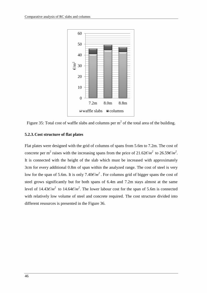
Comparative analysis of RC slabs and columns
46
Figure 35: Total cost of waffle slabs and columns per m2 of the total area of the building.
5.2.3. Cost structure of flat plates
Flat plates were designed with the grid of columns of spans from 5.6m to 7.2m. The cost of
concrete per m2 raises with the increasing spans from the price of 21.62€/m
2 to 26.59€/m
2.
It is connected with the height of the slab which must be increased with approximately
3cm for every additional 0.8m of span within the analyzed range. The cost of steel is very
low for the span of 5.6m. It is only 7.40€/m2
. For columns grid of bigger spans the cost of
steel grows significantly but for both spans of 6.4m and 7.2m stays almost at the same
level of 14.43€/m2
to 14.64€/m2. The lower labour cost for the span of 5.6m is connected
with relatively low volume of steel and concrete required. The cost structure divided into
different resources is presented in the Figure 36.
0
10
20
30
40
50
60
7.2m 8.0m 8.8m
€/m
2
waffle slabs columns

Analysis of results
47
Figure 36: Comparison of costs of materials and formwork and labour per m2 of total area
of building for flat plates.
The cost of columns reaches from 11.6% of the cost of slabs for the span of 7.2m to 15.4%
for the span of 5.6m. In the Figure 37 total cost of waffle slabs and columns per m2 of the
total area of the building is shown. The total cost of building slabs and columns are
estimated to equal the value from 48.06€/m2
for the span of 5.2m to 56.15€/m2 for the span
of 7.2m.
Figure 37: Total cost of flat plates and columns per m2 of the total area of the building
0
5
10
15
20
25
30
concrete steel formwork and
labour
€/m
2
5.6m
6.4m
7.2m
0
10
20
30
40
50
60
5.6m 6.4m 7.2m
€/m
2
flat plates columns

Comparative analysis of RC slabs and columns
48
5.2.4. Cost structure of slabs with beams
Slabs with beams were designed with the grid of columns of spans from 5.6m to 7.2m.
Cost of building the slab for the span of 5.6m per m2 of total area is very close to the price
for span of 7.2 m. The cost of concrete grows with the increasing spans form the price of
20.22€/m2
to 25.12€/m2. The cost of steel is rather high for the span of 5.6m. It is
26.08€/m2
. The cost of columns decreases with the increasing span from 9.99€/m2 for span
of 5.6m to 6.81€/m2 for the span of 7.2m. The labour cost for sll of the spans are similar
and fall within the ambit of 16.18€/m2
to 17.47€/m2. The cost structure divided into
different resources is presented in the Figure 38.
Figure 38: Comparison of costs of materials and formwork and labour per m2 of total area
of building for slabs with beams
The cost of columns supporting slabs with beams reaches from 12.0% of the cost of slabs
for the span of 7.2m to 18.4% for the span of 5.6m. In the Figure 39 total cost of slabs
with beams and columns per m2 of the total area of the building is shown. The total cost of
building slabs and columns are estimated to equal the value from 58.24€/m2
for the span of
6.4m to 64.18€/m2 for the span of 5.6 m.
0
5
10
15
20
25
30
concrete steel formwork and labour
€/m
2 5.6m
6.4m
7.2m

Analysis of results
49
Figure 39: Total cost of slabs with beams and columns per m2 of the total area of the
building
5.2.5. Comparison of different slab systems
As shown in Figure 40 for span of 7.2m the price for building one m2 of slab differs
significantly among different systems of flat slabs. The most economical is waffle slab and
the most expensive solution for this span is slab with beams which additionally have big
dimensions. The internal beams have width of 40cm what makes it very difficult to hide
them in internal walls. Flat plate and slab with column heads have similar cost in the
considered example.
0
10
20
30
40
50
60
70
5.6m 6.4m 7.2m
€/m
2
slabs with beams columns

Comparative analysis of RC slabs and columns
50
Figure 40: Total costs of slabs and columns per m2 of total area of building for span of
7.2m.
Figure 41: Comparison of costs of materials and formwork and labour per m2 of total area
of building for all considered slabs.
The highest price per m2 of total area is reached by the slab with beams for the span of
7.2m and it is equal to 56.66€/m2
. This type of slab is very expensive in all of considered
cases. It is the most economical for the span of 6.4m but still is 5.14% more expensive than
flat plate. For the span of 5.6m the difference in cost is even bigger and reaches 30%.
0
10
20
30
40
50
60
70
waffle slab flat plate slab with
column heads
slab with
beams
€/m
2
slabs columns
0
10
20
30
40
50
60
5.6m 6.4m 7.2m 8.0m 8.8m
€/m
2
waffle slab flat plate slab with column heads slab with beams

Analysis of results
51
The lowest price per m2 of total area is reached by the waffle slab for the span of 7.2m and
it is equal to 40.80€/m2
. For bigger spans the price for waffle slab does not change
significantly and reaches the value of 44.43€/m2
for span of 8.0m what is 8.88% more than
the lowest price . This type of slab is very economical in all of considered cases especially
when compared to slab with column heads for the span of 8.8m. For this span the solution
with column heads costs 30.7% more.

Comparative analysis of RC slabs and columns
52
6. FINAL CONCLUSIONS
For the slabs a significant part of the total volume of concrete for a bulding is used as they
have important roles in the structures. The choice of slab system must be performed taking
into account several aspects as economic evaluation, functionality, implementation, and the
interaction with other structural elements of the building. Therefore, the flat reinforced
concrete slabs constitute one of the best alternatives for the construction of floors of
buildings.
In the era of finite elements method usage of simplified methods may be helpful to
evaluate the dimensions of structural members. Knowledge of the simplified methods
helps to understand the mechanics of building and to find possible errors in computer
supported design. The simplified methods are methods for quick and easy use, however,
these are limited to slabs with repetitive supports and uniform loads.
The conclusion from the conducted calculation may be drawn that the cost of concrete as a
construction material is higher for the flat plate than for the slab with beams for every
span considered respectively but the cost in steel between these two systems is
significantly different. The slab with beams requires much more steel than flat plate what
makes flat plate more economical solution.
The comparison of costs of different types of flat slabs and columns made in this
dissertation was not meant to be very complex. The simplified methods used for designing
the structural members cannot be used for complex analysis but for simple grid of columns
were enough precise to shed light on different aspects which has to be take into
consideration and make the difference in the total cost. Therefore, besides knowledge
acquired in process of writing the dissertation, the objectives of it were achieved.

Bibliography
53
BIBLIOGRAPHY
BS 8110 (1997). “Structural use of concrete. Code of practice for design and construction”,
BSI, London.
Cachim, P. (2005). "Apontamentos de Estruturas de Betão." Universidade de Aveiro,
Aveiro.
Eurocode 0 (2009). "Basis of structural design." European Committee for Standardization,
Brussels.
Eurocode 1 (2009). "Part 1-1. General actions. Densities, self-weight, imposed loads for
builings." European Committee for Standardization, Brussels.
Eurocode 2 (2010). "Design of concrete structures - Part 1-1: General rules and rules for
buildings." European Committee for Standardization, Brussels.
Fercanorte (2013). <http://www.fercanorte.com.pt/moldes.htm>. (May, 2013).
Jiménez Montoya, P., García Meseguer, Á., e Morán Cabré, G. (2001). "Hormigón
Armado." Editorial Gustavo Gili, Barcelona.
Starosolski, W. (2003). “Konstrukcje żelbetowe. Tom II.” PWN, Warszawa.
Tesoro, F. R. (1991). "Los Forjados Reticulares. Manual Práctico." CYPE Ingenieros.
Trindade, M. d. O. (2009). "Estudo da Configuração Económica de Lajes Fungiformes
em Função da sua Geometria e Materiais." Universidade de Coimbra, Coimbra.
Wight, J.K. (2012). “Reinforced concrete: mechanics and design.” Pearson Education,
New Jersey.

Comparative analysis of RC slabs and columns
54
APPENDIX A.1
WAFFLE SLAB
7.2m x7.2m
Materials
Concrete fck fcm fctm Ecm ρc γc Steel fyk Es γs
C30/37 MPa MPa MPa GPa kN/m3 - A500 MPa GPa -
30 38 2.9 33 25.0 1.5 500 210 1.15
Actions
Category of loaded area: A - Areas for domestic and residential activities
Permanent actions
gk
Variable actions
qk
kN/m2
kN/m2
Imposed load 5.0
Imposed load 2.0
External walls 3.8
Pre-dimensioning of slab
concrete lightly stressed: ρ = 0,5%
l l/d d
m - cm
end span of two-way spanning slab continouos over one long side
7.2
26 27.7
interior span of two-way spanning slab 7.2
30 24.0
l - span
d - effective depth of a cross-section
Dimensioning of slab
Height of slab
lx ly l/d Østirrup Øbottom Øtop d cnom h
m m - mm mm mm mm mm mm
7.2 7.2 24.91 6 20 16 289 20 325
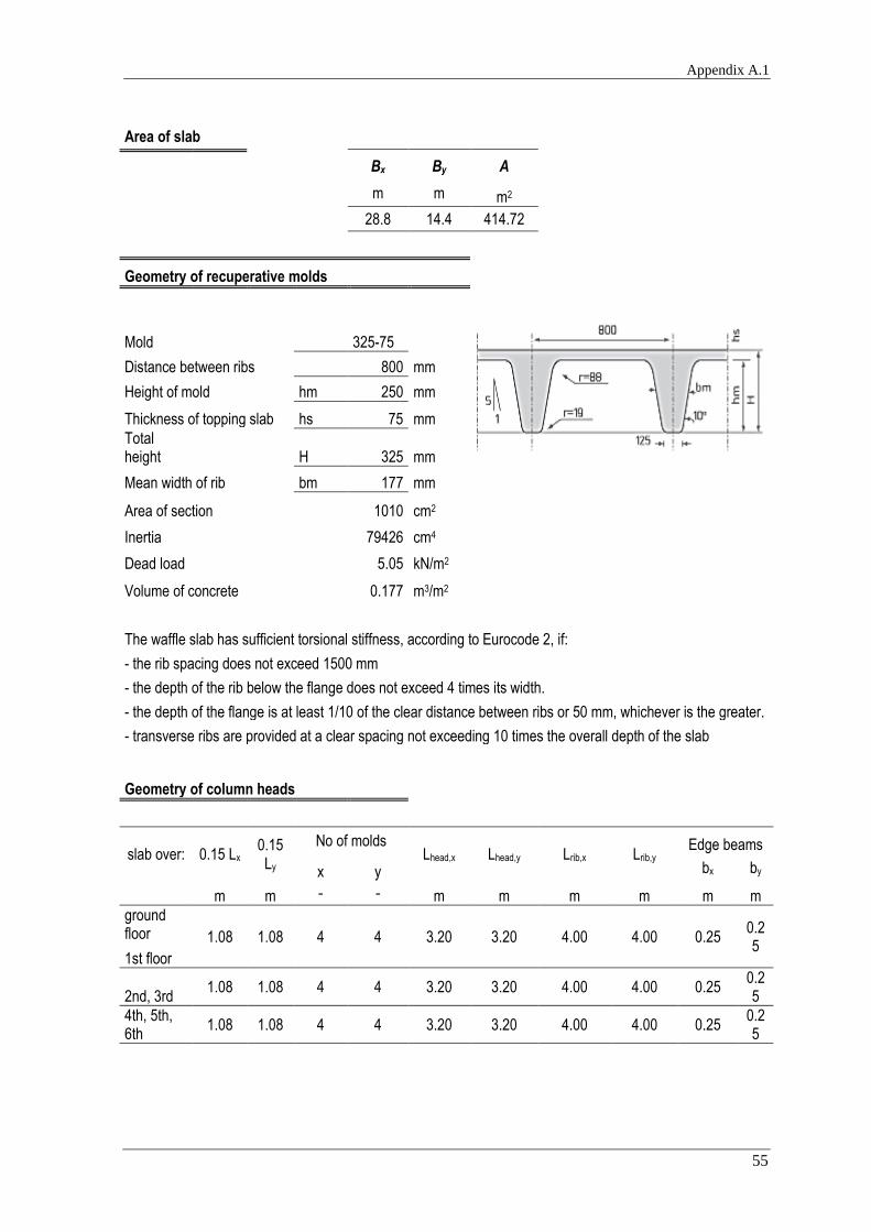
Appendix A.1
55
Area of slab
Bx By A
m m m2
28.8 14.4 414.72
Geometry of recuperative molds
Mold
325-75
Distance between ribs 800 mm Height of mold
hm 250 mm
Thickness of topping slab hs 75 mm
Total height
H 325 mm
Mean width of rib
bm 177 mm
Area of section
1010 cm2
Inertia
79426 cm4
Dead load
5.05 kN/m2
Volume of concrete
0.177 m3/m2
The waffle slab has sufficient torsional stiffness, according to Eurocode 2, if: - the rib spacing does not exceed 1500 mm
- the depth of the rib below the flange does not exceed 4 times its width. - the depth of the flange is at least 1/10 of the clear distance between ribs or 50 mm, whichever is the greater.
- transverse ribs are provided at a clear spacing not exceeding 10 times the overall depth of the slab
Geometry of column heads
slab over: 0.15 Lx
0.15 Ly
No of molds Lhead,x Lhead,y Lrib,x Lrib,y
Edge beams
x y bx by
m m - - m m m m m m
ground floor 1.08 1.08 4 4 3.20 3.20 4.00 4.00 0.25
0.25
1st floor
2nd, 3rd 1.08 1.08 4 4 3.20 3.20 4.00 4.00 0.25
0.25
4th, 5th, 6th
1.08 1.08 4 4 3.20 3.20 4.00 4.00 0.25 0.25

Comparative analysis of RC slabs and columns
56
Preidimensioning of columns
column on:
position of
column Ainf β c
m2 - m
1st floor
internal 51.84 1.15 0.55
edge 25.92 1.40 0.45
corner 12.96 1.50 0.35
2nd, 3rd
internal 51.84 1.15 0.50
edge 25.92 1.40 0.40
corner 12.96 1.50 0.30
4th, 5th, 6th
internal 51.84 1.15 0.40
edge 25.92 1.40 0.30
corner 12.96 1.50 0.30
β - recommended values where adjacent spans do not differ more than 25%
Ultimate limit state
Bending
Bending moments
Direction x
strip MEd,x,A MEd,x,1 MEd,x,B MEd,x,2 MEd,x,C
kNm kNm kNm kNm kNm
column 189.29 278.14 454.29 259.59 412.99
middle 81.12 185.42 194.70 173.06 177.00
Direction y
strip MEd,A MEd,1 MEd,B
kNm kNm kNm
column 189.29 278.14 504.77
middle 81.12 185.42 216.33

Appendix A.1
57
Calculation of bottom reinforcement
Minimum reinforcement in ribs of waffle slab
b
concrete cover
d As,min As,min,bottom
mm mm mm cm2/rib - cm2
125 20 289 0.54 2Ø8 1.01
Distance between bars
s ≥ 0.02m
Reinforcement in direction x
MEd μ ω As,min As,min/rib As/rib As,bottom
kNm - - cm2/m cm2 cm2 -
MSd,1
column strip 278.14 0.046 0.047 6.30 5.04 6.28 2Ø20
middle strip 185.42 0.031 0.031 4.17 3.33 4.02 2Ø16
MSd,2
column strip 259.59 0.043 0.044 5.87 4.70 6.28 2Ø20
middle strip 173.06 0.029 0.029 3.89 3.11 4.02 2Ø16
Reinforcement in direction y
MEd μ ω As,min As,min/rib As/rib As,bottom
kNm/m - - cm2/m cm2 cm2 -
MSd,1
column strip 278.14 0.046 0.047 6.30 5.04 6.28 2Ø20
middle strip 185.42 0.031 0.031 4.17 3.33 4.02 2Ø16

Comparative analysis of RC slabs and columns
58
Calculation of top reinforcement
Minimal reinforcement in topping slab
b concrete
cover d As,min 0.0013btd As,min,top
mm mm mm cm2/m cm2/m - cm2
1000 20 291 4.39 3.78 Ø8//0.10 5.03
Top reinforcement in direction x
MEd μ ω As As,top
kNm/m - - cm2/m - cm2/m
MSd,A column strip 189.29 0.031 0.032 4.23 Ø8//0.10 5.03
middle strip 81.12 0.013 0.013 1.79 Ø8//0.10 5.03
MSd,B column strip 454.29 0.075 0.078 10.39 Ø12//0.10 11.31
middle strip 194.70 0.032 0.032 4.35 Ø8//0.10 5.03
MSd,C column strip 412.99 0.068 0.070 9.41 Ø12//0.10 11.31
middle strip 177.00 0.029 0.029 3.95 Ø8//0.10 5.03
Top reinforcement in direction y
MEd μ ω As As,top
kNm/m - - cm2/m - cm2/m
MSd,A column strip 189.29 0.031 0.032 4.23 Ø8//0.10 5.03
middle strip 81.12 0.013 0.013 1.79 Ø8//0.10 5.03
MSd,B column strip 504.77 0.083 0.087 11.60 Ø16//0.15 13.40
middle strip 216.33 0.035 0.036 4.84 Ø8//0.10 5.03

Appendix A.1
59
Shear force
Verification of shear resistance shoudl be checked in proximity of drop panels.
Shear force in ribs according to Tesoro (1991)
n K B = L P1 Qa VEd
- - m kN/m2 kN kN
8 0.9 7.2 20.55 213.06 53.27
8 1.1 7.2 20.55 260.41 65.10
8 1.0 7.2 20.55 236.74 59.18
8 1.0 7.2 20.55 236.74 59.18
In direction x
support A Bleft Bright C
kN kN kN kN
VEd 53.27 65.10 59.18 59.18
In direction y
support A B
kN kN
VEd 53.27 65.10
Members not requiring design shear reinforcement
fck d CRd,c k bw As,bottom Asl ρl vmin VRd,c vminbwd
MPa mm - - m - cm2 - kPa kN kN
30 289 0.12 1.83 0.135 2Ø16 4.02 0.0103069 475.31 26.92 18.54
30 289 0.12 1.83 0.135 2Ø20 6.28 0.0161045 475.31 31.24 18.54

Comparative analysis of RC slabs and columns
60
Calculation of shear reinforcement
Maximum longitudinal spacing of the stirrups assemblies
d α cotα sl,max
m ° - m
0.289 90 0 0.21675
The transverse spacing of the legs in a series of shear links
d st,max
m m
0.289 0.4335
Minimal reinforcement in a rib
fck fyk ρw,min α bw Asw,min/s Asw/s
MPa MPa - ° m cm2/m cm2/m
30 500 0.00088 90 0.135 1.18 2.83 Ø6 // 0.20
Shear reinforcement in ribs
αcw bw d z ν1 fcd cotΘ VRd,max
- m m m - MPa - kN
1 0.135 0.292 0.263 0.6 20 2.5 146.81
VEd fywd Asw/s assumed (2 legs)
Asw/s
kN MPa cm2/m - cm2/m
53.27 435 1.86 Ø6 // 0.20 2.83
65.10 435 2.28 Ø6 // 0.20 2.83
59.18 435 2.07 Ø6 // 0.20 2.83
Minimum shear reinforcement should be used in every section where bigger is not required.

Appendix A.1
61
Punching
Vertical force
column VEd
kN
internal 901.37
edge 543.02
corner 317.68
Punching shear resistance without shear reinforcement vRd,c
Punching shear resistance without shear reinforcement
frame in
direction x support
position of
column As,top,x As,top,y ρl,head vRd,c vmin
cm2/m cm2/m - kPa kPa
exterior A corner 5.03 5.03 1.73E-06 38.04
475.31
B edge 11.31 5.03 2.59E-06 43.55
C edge 11.31 5.03 2.59E-06 43.55
interior A edge 5.03 13.40 2.82E-06 44.80
B internal 11.31 13.40 4.23E-06 51.28
C internal 11.31 13.40 4.23E-06 51.28
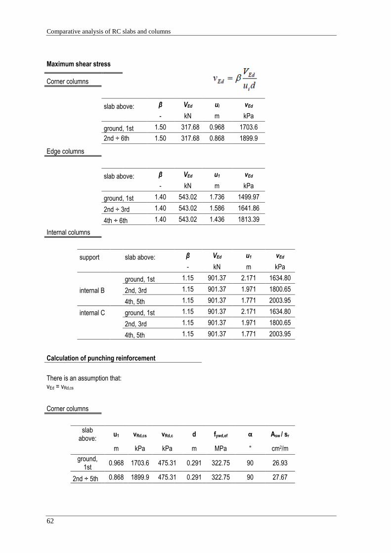
Comparative analysis of RC slabs and columns
62
Maximum shear stress
Corner columns
slab above: β VEd ui vEd
- kN m kPa
ground, 1st 1.50 317.68 0.968 1703.6
2nd ÷ 6th 1.50 317.68 0.868 1899.9
Edge columns
slab above: β VEd u1 vEd
- kN m kPa
ground, 1st 1.40 543.02 1.736 1499.97
2nd ÷ 3rd 1.40 543.02 1.586 1641.86
4th ÷ 6th 1.40 543.02 1.436 1813.39
Internal columns
support slab above: β VEd u1 vEd
- kN m kPa
ground, 1st 1.15 901.37 2.171 1634.80
internal B
2nd, 3rd 1.15 901.37 1.971 1800.65
4th, 5th 1.15 901.37 1.771 2003.95
internal C ground, 1st 1.15 901.37 2.171 1634.80
2nd, 3rd 1.15 901.37 1.971 1800.65
4th, 5th 1.15 901.37 1.771 2003.95
Calculation of punching reinforcement
There is an assumption that: vEd = vRd,cs
Corner columns
slab above:
u1 vRd,cs vRd,c d fywd,ef α Asw / sr
m kPa kPa m MPa ° cm2/m
ground, 1st
0.968 1703.6 475.31 0.291 322.75 90 26.93
2nd ÷ 5th 0.868 1899.9 475.31 0.291 322.75 90 27.67

Appendix A.1
63
Edge columns
slab above:
u1 vRd,cs vRd,c d fywd,ef α Asw / sr
m kPa kPa m MPa ° cm2/m
ground 1st
1.736 1500.0 475.31 0.291 322.75 90 41.00
2nd ÷ 3rd
1.586 1641.9 475.31 0.291 322.75 90 42.10
4th ÷ 5th
1.436 1813.4 475.31 0.291 322.75 90 43.21
Internal columns
support slab
above: β VEd u1 vRd,cs vRd,c d fywd,ef α
Asw / sr
- kN m kPa kPa m MPa ° cm2/
m
ground
1st 1.15 901.37 2.171 1634.80 475.31 0.291 322.75 90 57.34
internal 1 2nd, 3rd
1.15 901.37 1.971 1800.65 475.31 0.291 322.75 90 58.81
4th, 5th,
1.15 901.37 1.771 2003.95 475.31 0.291 322.75 90 60.28
internal 2 ground
1st 1.15 901.37 2.171 1634.80 475.31 0.291 322.75 90 57.34
2nd, 3rd
1.15 901.37 1.971 1800.65 475.31 0.291 322.75 90 58.81
4th, 5th
1.15 901.37 1.771 2003.95 475.31 0.291 322.75 90 60.28
assumed distance
m m
d 0.291
0.3d 0.087 0.1
0.75d 0.218 0.2
kd 0.437
The recommended value for k is 1.5.

Comparative analysis of RC slabs and columns
64
Punching shear reinforcement should be placed between the column and kd inside the control perimeter at which shear reinforcement is no longer required.
Calculation of punching reinforcement
storey uout,ef r c sr Asw Asw / sr min Asw / sr
m m m m cm2 cm2/m cm2/m
Corner columns
1st, 2nd 3.45 1.97 0.35 0.20 5.65 28.27 26.93
2nd ÷ 6th
3.45 2.00 0.30 0.20 5.65 28.27 27.67
Edge columns
1st, 2nd 5.50 1.62 0.40 0.20 9.05 45.24 41.00
3rd, 4th 5.50 1.64 0.35 0.20 9.05 45.24 42.10
5th, 6th 5.50 1.65 0.30 0.20 9.05 45.24 43.21
Internal columns
1st, 2nd 7.49 1.19 0.55 0.20 13.57 67.86 57.34
3rd, 4th 7.49 1.19 0.45 0.20 13.57 67.86 58.81
5th, 6th 7.49 1.19 0.35 0.20 13.57 67.86 60.28

Appendix A.1
65
storey
reinforcement per perimeter
Number of perimeters
Verification of the
distance* ≤
kd=0.437m
Verification of the spacing¹ ≤ 2d=0.582m
rassumed robligatory
Corner columns
1st, 2nd 5#12 8 0.14 0.52 1.68 1.53
2nd ÷ 6th 5#12 8 0.08 0.52 1.65 1.57
Edge columns
1st, 2nd 8#12 6 0.11 0.51 1.30 1.19
3rd, 4th
8#12 6 0.07 0.50 1.28 1.20
5th, 6th 8#12 6 0.03 0.49 1.25 1.22
Internal columns
1st, 2nd 12#12 3 0.02 0.40 0.78 0.76
3rd, 4th
12#12 4 0.17 0.48 0.93 0.76
5th, 6th 12#12 4 0.12 0.45 0.875 0.76
* - the distance between the outermost perimeter of shear reinforcement and the control perimeter uout
¹ - the spacing of link legs around a perimeter should not exceed 2d
Edge beams
Minimum reinforcement
b
concrete cover
d As,min 0.0013btd As
mm mm mm cm2/m cm2/m - cm2
250 20 366 1.38 1.19 2 Ø12 2.26

Comparative analysis of RC slabs and columns
66
Bottom reinforcement
MEd μ ω As,min As
kNm - - cm2 - cm2/m
V1 28.75 0.069 0.071 2.38 2Ø16 4.02
V2 23.00 0.055 0.057 1.89 2Ø12 2.26
V3 28.75 0.069 0.071 2.38 2Ø16 4.02
Top reinforcement
MEd μ ω As,min As
kNm - - cm2 - cm2/m
V1
edge 27.60 0.066 0.069 2.28 2Ø16 4.02
internal 48.30 0.116 0.124 4.11 2Ø20 6.28
V2
internal 41.40 0.099 0.105 3.48 2Ø16 4.02
internal 41.40 0.099 0.105 3.48 2Ø16 4.02
V3
edge 27.60 0.066 0.069 2.28 2Ø16 4.02
internal 48.30 0.116 0.124 4.11 2Ø20 6.28
Verification of shear force should be defined in proximity of column head.
support VEd
kNm
V1 edge 51.91
internal 62.29
V2 internal 57.10
internal 57.10
V3 edge 51.91
internal 62.29

Appendix A.1
67
Members not requiring design shear reinforcement
Beam fck d CRd,c k b Asl ρl vmin VRd,c vminbwd
MPa m - - m cm2 - kPa kN kN
V1
30 0.366 0.12 1.02 0.25 3.77 0.0041201 198.46 25.98 18.16 V2
V3
Calculation of shear reinforcement
Maximum longitudinal spacing of the stirrups assemblies
d α cotα sl,max
m ° - m
0.289 90 0 0.21675
Minimum reinforcement
fck fyk ρw,min α bw Asw,min/s Asw/s
MPa MPa - ° m cm2/m cm2/m -
30 500 0.00088 90 0.25 2.19 2.83 Ø6 // 0.20 2 legs

Comparative analysis of RC slabs and columns
68
Shear reinforcement
fck αcw bw d z ν1 fcd cotΘ VRd,max
MPa - m m m - MPa - kN
30 1 0.25 0.289 0.260 0.528 20 2.5 236.78
Shear reinforcement
support VEd Asw/s Assumed reinforcement
kN cm2/m cm2/m -
V1 edge 51.91 1.84
2.83 Ø6 // 0.20 2 legs
internal 62.29 2.20
V2 internal 57.10 2.02
internal 57.10 2.02
V3 edge 51.91 1.84
internal 62.29 2.20
Assumed shear reinforcement:
Ø6 // 0.20

Appendix A.1
69
APPENDIX A.2
SLAB WITH COLUMN HEADS
7.2m x7.2m
Materials
Concrete fck fcm fctm Ecm ρc γc Steel fyk Es γs
C30/37 MPa MPa MPa GPa kN/m3 - A500 MPa GPa -
30 38 2.9 33 25.0 1.5 500 210 1.15
Actions
Category of loaded area:
A - Areas for domestic and residential activities
Permanent actions
gk
Variable actions
qk
kN/m2
kN/m2
Imposed load 5.0
Imposed load 2.0
External walls 3.8
pd
kN/m2
total design load 17.33
Pre-dimensioning of slab
concrete lightly stressed: ρ = 0,5%
l l/d d
m - cm
Slab supported on columns without beams 7.2 24 30.0
l - span
d - effective depth of a cross-section
Dimensioning of slab
Area of slab
Bx By A
m m m2
28.8 14.4 414.72

Comparative analysis of RC slabs and columns
70
Geometry of column heads
lx/3 ly/3 Lhead,x Lhead,y Lslab,x Lslab,y
Edge beams
bx by
m m m m m m m m
2.40 2.40 2.40 2.40 4.8 4.8 0.25 0.25
Geometry of slab
l/d dslab hslab hhead hH 0.03l Verification
- m m m m m hH < 0.03l
30 0.16 0.20 0.40 0.20 0.216 correct
Predimensioning of columns
column on:
position of
column Ainf β c
m2 - m
ground, 1st floor
internal 51.84 1.15 0.50
edge 25.92 1.40 0.40
corner 12.96 1.50 0.30
2nd, 3rd
internal 51.84 1.15 0.45
edge 25.92 1.40 0.35
corner 12.96 1.50 0.30
4th, 5th, 6th
internal 51.84 1.15 0.35
edge 25.92 1.40 0.30
corner 12.96 1.50 0.30
Reinforcement ratio assumed in columns: 2%
c - dimension of column side
β - recommended values where adjacent spans do not differ more than 25%

Appendix A.1
71
Ultimate limit state
Bending
Bending moments
Direction x
strip MEd,x,A MEd,x,1 MEd,x,B MEd,x,2 MEd,x,C
kNm kNm kNm kNm kNm
column 188.66 277.22 452.79 258.74 411.62
middle 80.85 184.81 194.05 172.49 176.41
Direction y
strip MEd,A MEd,1 MEd,B
kNm kNm kNm
column 188.66 277.22 503.10
middle 80.85 184.81 215.61
Height of a slab area
Øbottom,x Øbottom,y dslab,x dslab,y cnom h
mm mm mm mm mm mm
12 16 158 172 20 200
A
External
Support
B
Internal
Support
C
Internal
Support
A
External
Support
B
Internal
Support
External
Span 1
Ext
erna
l
Spa
n 1
External
frame
Internal
frame
External
frame
Inte
rnal
fram
e
Inte
rnal
fram
e
Inte
rnal
fram
e
Ext
erna
l
fram
e
Ext
erna
l
fram
e
Fra
mes
in x
dire
ctio
n
Frames in y direction
A
External
Support
B
Internal
Support
Ext
erna
l
Spa
n 1
Internal
Span 2
Internal
Span 2
External
Span 1

Comparative analysis of RC slabs and columns
72
Calculation of bottom reinforcement
Minimum reinforcement
b
concrete cover
d As,min 0.0013btd As,min,bottom
mm mm mm cm2/m cm2/m - cm2
1000 20 158 2.38 2.05 Ø8//0.20 2.51
1000 20 172 2.59 2.24 Ø8//0.20 2.51
Distance between bars
s ≥ 0.02m
Reinforcement in direction x
`
MEd μ ω As,min As,bottom
kNm/m - - cm2/m - cm2/m
MEd,1 column strip 277.22 0.154 0.169 12.28 Ø16//150 13.40
middle strip 184.81 0.103 0.109 7.92 Ø12//125 9.05
MEd,2 column strip 258.74 0.144 0.157 11.38 Ø16//150 13.40
middle strip 172.49 0.096 0.101 7.36 Ø12//150 7.54
Reinforcement in direction y
MEd μ ω As,min As,bottom
kNm/m - - cm2/m - cm2/m
MEd,1 column strip 277.22 0.130 0.140 11.10 Ø16//150 13.40
middle strip 184.81 0.087 0.091 7.20 Ø12//150 7.54

Appendix A.1
73
Calculation of top reinforcement
Height of a column head area
Øtop,x Øtop,y dhead,x dhead,y cnom hH
mm mm mm mm mm mm
16 16 356 372 20 400
Minimum reinforcement
b
concrete cover
d As,min 0.0013btd As,min,to
mm mm mm cm2/m cm2/m - cm2
1000 20 372 5.61 4.84 Ø10//150 5.24
1000 20 365 5.50 4.75 Ø10//150 5.24
Top reinforcement in direction x
MEd b μ ω As As,top,x
kNm m - - cm2/m - cm2/m
MSd,A column strip 188.66
3.6
0.021 0.021 3.42 Ø10//1
50 5.24
middle strip 80.85 0.045 0.046 3.35
Ø10//150
5.24
MSd,B column strip 452.79 0.050 0.051 8.35
Ø16//200
10.05
middle strip 194.05 0.108 0.115 8.34
Ø16//200
10.05
MSd,C column strip 411.62 0.045 0.046 7.57
Ø12//150
7.54
middle strip 176.41 0.098 0.104 7.54
Ø12//150
7.54

Comparative analysis of RC slabs and columns
74
Top reinforcement in direction y
MEd b μ ω As As,top,y
kNm m - - cm2/m - cm2/m
MSd,A
column strip 188.66
3.6
0.019 0.019 3.58 Ø10//150 5.24
middle strip 80.85 0.038 0.039 3.65 Ø10//150 5.24
MSd,B
column strip 503.10 0.050 0.052 8.72 Ø16//200 10.05
middle strip 215.61 0.101 0.107 9.08 Ø16//200 10.05
Punching
Vertical force
column position
internal edge corner
VEd kN 894.24 539.46 315.90
Dimensions
hslab d hhead dH hH lH Lhead
m m m m m m m
0.20 0.165 0.40 0.364 0.20 0.90÷1.05 2.40
For slabs with enlarged column heads where lH > 2hH control sections both within the head and in the slab should be checked.

Appendix A.1
75
Punching shear resintance without shear reinforcement vRd,c
kslab dslab khead dhead CRd,c
calculated assumed
- - - -
2.101 2.000 0.165 1.741 0.364 0.120
Punching shear resistance without shear reinforcement within the head
head slab
frame in direction
x support
position of
column As,top,x As,top,y ρl,head vRd,c vmin ρl,slab vRd,c vmin
cm2/m cm2/m - kPa kPa - kPa kPa
exterior A corner 5.24 5.24 0.001438 340.18
440.47
0.003173 508.65
542.22
B edge 10.05 5.24 0.001993 379.26 0.004397 567.07
C edge 7.54 5.24 0.001726 361.50 0.003808 540.53
interior A edge 5.24 10.05 0.001993 379.26 0.004397 567.07
B internal 10.05 10.05 0.002762 422.81 0.006093 632.20
C internal 7.54 10.05 0.002392 403.02 0.005277 602.61

Comparative analysis of RC slabs and columns
76
Verification of necessity of use of shear punching reinforcement in the column head
storey c lH u1 β VEd vEd vRd,c Necessity of using shear
punching reinforcement
m m m - kN kPa kPa
Corner columns
1st, 2nd 0.30 1.05
1.74 1.50 315.90 746.63 440.47
necessary
3rd, 4th 0.30 1.05
1.74 1.50 315.90 746.63 440.47
5th, 6th 0.30 1.05
1.74 1.50 315.90 746.63 440.47
Edge columns
1st, 2nd 0.40 1.00
3.49 1.40 539.46 595.01 440.47
necessary
3rd, 4th 0.35 1.03
3.34 1.40 539.46 621.76 440.47
5th, 6th 0.30 1.05
3.19 1.40 539.46 651.02 440.47
Internal columns B
1st, 2nd 0.50 0.95
6.57 1.15 894.24 429.74 440.47 not necessary
3rd, 4th 0.45 0.98
6.37 1.15 894.24 443.23 440.47
necessary
5th, 6th 0.35 1.03
6.17 1.15 894.24 457.89 440.47
Internal columns C
1st, 2nd 0.50 0.95
6.57 1.15 894.24 429.74 440.47 not necessary
3rd, 4th 0.45 0.98
6.37 1.15 894.24 443.23 440.47
necessary
5th, 6th 0.35 1.03
6.17 1.15 894.24 457.89 440.47
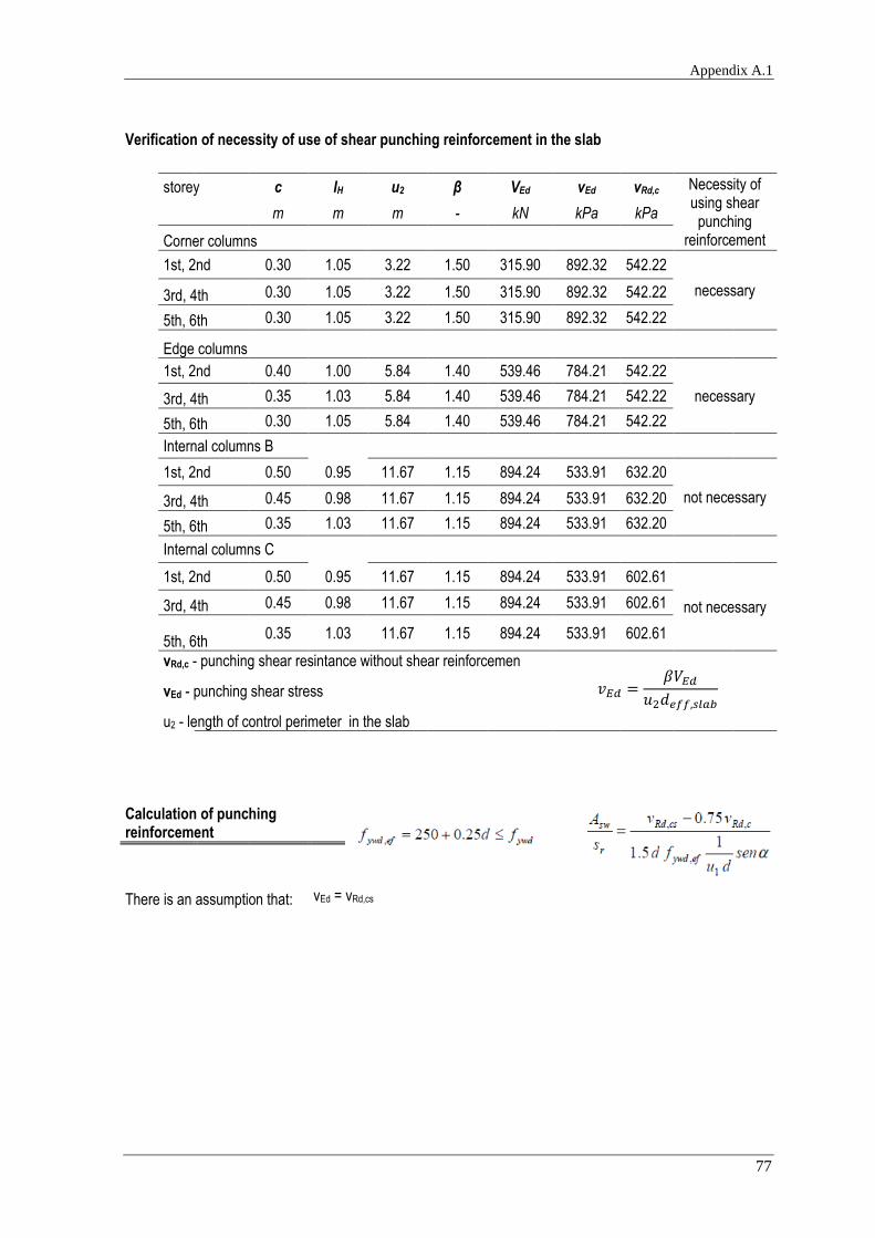
Appendix A.1
77
Verification of necessity of use of shear punching reinforcement in the slab
storey c lH u2 β VEd vEd vRd,c Necessity of using shear
punching reinforcement
m m m - kN kPa kPa
Corner columns
1st, 2nd 0.30 1.05 3.22 1.50 315.90 892.32 542.22
necessary
3rd, 4th 0.30 1.05 3.22 1.50 315.90 892.32 542.22
5th, 6th 0.30 1.05 3.22 1.50 315.90 892.32 542.22
Edge columns
1st, 2nd 0.40 1.00 5.84 1.40 539.46 784.21 542.22
necessary
3rd, 4th 0.35 1.03 5.84 1.40 539.46 784.21 542.22
5th, 6th 0.30 1.05 5.84 1.40 539.46 784.21 542.22
Internal columns B
1st, 2nd 0.50 0.95 11.67 1.15 894.24 533.91 632.20
not necessary
3rd, 4th 0.45 0.98 11.67 1.15 894.24 533.91 632.20
5th, 6th 0.35 1.03 11.67 1.15 894.24 533.91 632.20
Internal columns C
1st, 2nd 0.50 0.95 11.67 1.15 894.24 533.91 602.61
not necessary
3rd, 4th 0.45 0.98 11.67 1.15 894.24 533.91 602.61
5th, 6th
0.35 1.03 11.67 1.15 894.24 533.91 602.61
vRd,c - punching shear resintance without shear reinforcemen
vEd - punching shear stress
u2 - length of control perimeter in the slab
Calculation of punching reinforcement
There is an assumption that: vEd = vRd,cs

Comparative analysis of RC slabs and columns
78
Shear punching reinforcement in the column head
Corner columns
storey u1 vRd,cs vRd,c d fywd,ef α Asw / sr
m kPa kPa m MPa ° cm2/m
1st, 2nd
1.744 746.6 440.47 0.364 341
90
14.19
3rd, 4th
1.744 746.6 440.47 0.364 341 14.19
5th, 6th
1.744 746.6 440.47 0.364 341 14.19
Edge columns
storey u1 vRd,cs vRd,c d fywd,ef α Asw / sr
m kPa kPa m MPa ° cm2/m
1st, 2nd
3.487 595.0 440.47
0.364
341
90
18.04
3rd, 4th
3.337 621.8 440.47 341 19.01
5th, 6th
3.187 651.0 440.47 341 19.98
Internal columns
storey u1 vRd,cs vRd,c d fywd,ef α Asw / sr
m kPa kPa m MPa ° cm2/m
Internal columns B
3rd, 4th
6.374 443.2 440.47 0.364
341 90
14.07
5th, 6th
6.170 457.9 440.47 341 15.38
Internal columns C
3rd, 4th
6.574 443.2 440.47 0.364
341 90
14.51
5th, 6th
6.374 457.9 440.47 341 15.89

Appendix A.1
79
Shear punching reinforcement in the slab
Corner columns
storey u2 vRd,cs vRd,c d fywd,ef α Asw / sr
m kPa kPa m MPa ° cm2/m
1st, 2nd
3.218 892.3 542.22 0.165 291.25 90 35.78
3rd, 4th
3.218 892.3 542.22 0.165 291.25 90 35.78
5th, 6th
3.218 892.3 542.22 0.165 291.25 90 35.78
Edge columns
storey u2 vRd,cs vRd,c d fywd,ef α Asw / sr
m kPa kPa m MPa ° cm2/m
1st, 2nd
5.837 784.2 542.22 0.165 291.25 90 50.44
3rd, 4th
5.837 784.2 542.22 0.165 291.25 90 50.44
5th, 6th
5.837 784.2 542.22 0.165 291.25 90 50.44
head slab
m m
d 0.364 0.165
0.3d 0.109 0.050
0.5d 0.182 0.0825
0.75d 0.273 0.124
kd 0.546 0.248
The distance between the face of a support and the nearest shear reinforcement
The recommended value for k is 1.5. Punching shear reinforcement should be placed between
the column and kd inside the control perimeter at which shear reinforcement is no longer
required. The distance between the face of a support and the nearest shear reinforcement taken into account in the
design should not exceed d/2 (Eurocode 2, 2010) For slabs with enlarged column heads where lH > 2hH control sections both within the head and in the slab should be checked.

Comparative analysis of RC slabs and columns
80
The control perimeter at which shear reinforcement is not required uout
deff,head = dH
deff,slab Lhead,x Lhead,y
m m m m
0.364 0.165 2.40 2.40
Calculation of punching reinforcement in column heads
storey uout
uout,ef rout sr Asw studs
Num
ber
of p
erim
eter
s
Asw / sr
(Asw
/ s r
) MIN
Ver
ifica
tion
of th
e
dist
ance
*
≤ k
d=0.
552m
Ver
ifica
tion
of th
e
spac
ing¹
≤ 2
d=0.
736m
m m m cm2 cm2/m cm2/m m m
Corner columns
1st, 2nd 2.96 1.69 0.270 3.39 3#12 4 12.57 14.19 -0.002 0.591
3rd, 4th 2.96 1.69 0.275 3.39 3#12 4 12.34 14.19 0.013 0.599
5th, 6th 2.96 1.69 0.275 3.39 3#12 4 12.34 14.19 0.013 0.599
Edge columns
1st, 2nd 4.71 1.37 0.27 3.93 5#10 2 14.54 18.04 -0.174 0.403
3rd, 4th 4.71 1.39 0.27 3.93 5#10 3 14.54 19.01 0.055 0.554
5th, 6th 4.71 1.40 0.27 5.65 5#12 3 20.94 19.98 0.014 0.539
Internal columns B
3rd, 4th 6.41 1.90 0.27 5.65 5#12 5 20.94 14.07 0.060 0.628
5th, 6th 6.41 1.93 0.27 5.65 5#12 5 20.94 15.38 0.028 0.551
Internal columns C
3rd, 4th 6.41 1.90 0.27 5.65 5#12 5 20.94 14.51 0.060 0.442
5th, 6th 6.41 1.93 0.27 5.65 5#12 5 20.94 15.89 0.028 0.402
* - the distance between the outermost perimeter of shear reinforcement and the control perimeter uout
¹ - the spacing of link legs around a perimeter should not exceed 2d

Appendix A.1
81
Calculation of punching reinforcement within slab
storey uout
uout,ef rout sr Asw studs
Num
ber
of p
erim
eter
s
Asw / sr
(Asw
/ s r
) MIN
Ver
ifica
tion
of th
e di
stan
ce*
≤ k
d=0.
248m
Ver
ifica
tion
of th
e sp
acin
g**
≤ 2
d=0.
33m
m m m cm2 cm2/m cm2/m m m
Corner columns
1st, 2nd 5.30 3.18 0.250 12.57 16#10 3 50.27 35.78 0.049 0.293
3rd, 4th 5.30 3.18 0.250 12.57 16#10 3 50.27 35.78 0.049 0.293
5th, 6th 5.30 3.18 0.250 12.57 16#10 3 50.27 35.78 0.049 0.293
Edge columns
1st, 2nd 8.44 2.56 0.25 16.08 24#10 2 64.34 50.44 0.420 0.357
3rd, 4th 8.44 2.58 0.25 16.08 24#10 2 64.34 50.44 0.404 0.357
5th, 6th 8.44 2.59 0.25 16.08 24#10 2 64.34 50.44 0.388 0.357
* - the distance between the outermost perimeter of shear reinforcement and the control perimeter uout
** - the spacing of link legs around a perimeter should not exceed 2d
Edge beams
Minimal reinforcement
b
concrete cover
d As,min 0.0013btd As
mm mm mm cm2/m cm2/m - cm2
250 20 368 1.39 1.20 2 Ø12 2.26

Comparative analysis of RC slabs and columns
82
Bottom reinforcement
MEd μ ω As,min As
kNm - - cm2 - cm2/m
V1 28.68 0.043 0.044 1.40 2Ø12 2.26
V2 22.94 0.035 0.035 1.12 2Ø12 2.26
V3 28.68 0.043 0.044 1.40 2Ø12 2.26
Top reinforcement
MEd μ ω As,min As
kNm - - cm2 - cm2/m
V1
edge 27.53 0.042 0.042 1.35 2Ø12 2.26
internal 48.18 0.073 0.076 2.40 2Ø16 4.02
V2
internal 41.29 0.062 0.064 2.04 2Ø12 2.26
internal 41.29 0.062 0.064 2.04 2Ø12 2.26
V3
edge 27.53 0.042 0.042 1.35 2Ø12 2.26
internal 48.18 0.073 0.076 2.40 2Ø16 4.02
Verification of shear force should be defined in proximity of column head.
support VEd
kNm
V1 edge 51.76
internal 62.11
V2 internal 56.94
internal 56.94
V3 edge 51.76
internal 62.11

Appendix A.1
83
Members not requiring design shear reinforcement
Beam fck d CRd,c k b Asl ρl vmin VRd,c
vminb
wd
MPa m - - m cm2 - kPa kN kN
V1
30 0.364 0.12 1.74 0.25 3.77 0.00414 440.47 44.04 40.08 V2
V3
Calculation of shear reinforcement
Maximum longitudinal spacing of the stirrups
d α
cotα sl,max
m ° - m
0.364 90 0 0.273
Minimum reinforcement
fck fyk ρw,min α bw Asw,min/s Asw/s
MPa MPa - ° m cm2/m cm2/m -
30 500 0.00088 90 0.25 2.19 2.26 Ø6 // 0.25 2 legs

Comparative analysis of RC slabs and columns
84
Shear reinforcement
fck αcw bw d z ν1 fcd cotΘ VRd,max
MPa - m m m - MPa - kN
30 1 0.25 0.364 0.328 0.528 20 2.5 298.23
support VEd Asw/s Assumed reinforcement
kN cm2/m cm2/m -
V1 edge 51.76 1.45
2.26 Ø6 // 0.25 2 legs
internal 62.11 1.74
V2 internal 56.94 1.60
internal 56.94 1.60
V3 edge 51.76 1.45
internal 62.11 1.74
Assumed shear reinforcement:
Ø6 // 0.25

Appendix A.3
85
APPENDIX A.3
FLAT PLATE WITH SPANDREL BEAMS
7.2m x7.2m
Materials
Concrete fck fcm fctm Ecm ρc γc Steel fyk Es γs
C30/37 MPa MPa MPa GPa kN/m3 - A500 MPa GPa -
30 38 2.9 33 25.0 1.5 500 210 1.15
Actions
Category of loaded area:
A - Areas for domestic and residential activities
Permanent actions gk
Variable actions qk
kN/m2
kN/m2
Imposed load 5.0
Imposed load 2.0
External walls 3.8
pd
kN/m2
total design load 20.89
Predimensioning of slab
concrete lightly stressed: ρ = 0,5%
l l/d d
m - cm
Slab supported on columns without beams 7.2
24 30.0
l - span
d - effective depth of a cross-section
Dimensioning of slab
Area of slab
Bx By A
m m m2
28.8 14.4 414.72

Comparative analysis of RC slabs and columns
86
Geometry of slab
l/d dslab hslab
- m m
24 0.30 0.33
Dimensioning of columns
column on:
position of column
Ainf β c
m2 - m
ground
, 1st floor
internal 51.84 1.15 0.55
edge 25.92 1.40 0.45
corner 12.96 1.50 0.35
2nd, 3rd
internal 51.84 1.15 0.45
edge 25.92 1.40 0.40
corner 12.96 1.50 0.30
4th, 5th, 6th
internal 51.84 1.15 0.35
edge 25.92 1.40 0.30
corner 12.96 1.50 0.30
Reinforcement ratio assumed in columns: 2%
β - recommended values where adjacent spans do not differ more than 25%
Ultimate limit state
Bending
Bending moments
A
External
Support
B
Internal
Support
C
Internal
Support
A
External
Support
B
Internal
Support
External
Span 1
Ext
erna
l
Spa
n 1
External
frame
Internal
frame
External
frame
Inte
rnal
fram
e
Inte
rnal
fram
e
Inte
rnal
fram
e
Ext
erna
l
fram
e
Ext
erna
l
fram
e
Fra
mes
in x
dire
ctio
n
Frames in y direction
A
External
Support
B
Internal
Support
Ext
erna
l
Spa
n 1
Internal
Span 2
Internal
Span 2
External
Span 1

Appendix A.3
87
Direction x
strip MEd,x,A MEd,x,1 MEd,x,B MEd,x,2 MEd,x,C
kNm kNm kNm kNm kNm
column 227.42 334.16 545.80 311.89 496.18
middle 97.46 222.78 233.91 207.92 212.65
Direction y
strip MEd,A MEd,1 MEd,B
kNm kNm kNm
column 227.42 334.16 606.45
middle 97.46 222.78 259.91
Height of a slab area
Øbotto
m,x Øbottom,
y dslab,x dslab,y cnom h
mm mm mm mm mm mm
16 12 290 304 20 330
Calculation of bottom reinforcement
Minimum reinforcement
b
concrete cover
d As,min 0.0013btd As,min,bottom
mm mm mm cm2/m cm2/m - cm2
1000 20 290 4.37 3.77 Ø8//0.125 4.02
1000 20 304 4.58 3.95 Ø8//0.125 4.02
Distance between bars
s ≥ 0.02m

Comparative analysis of RC slabs and columns
88
Reinforcement in direction x
`
MEd μ ω As,min As,bottom
kNm/m - - cm2/m - cm2/
m
MEd,1 column strip 334.16 0.055 0.057 7.59 Ø12//150 7.54
middle strip 222.78 0.037 0.038 5.01 Ø10//150 5.24
MEd,2 column strip 311.89 0.052 0.053 7.07 Ø12//150 7.54
middle strip 207.92 0.034 0.035 4.67 Ø10//150 5.24
Reinforcement in direction y
MEd μ ω As,min As,bottom
kNm/m - - cm2/
m -
cm2/m
MEd,1 column strip 334.16 0.050 0.052 7.22 Ø12//150 7.54
middle strip 222.78 0.033 0.034 4.77 Ø10//150 5.24
Calculation of top reinforcement
Top reinforcement in direction x
MEd b μ ω As As,top,x
kNm m - - cm2/m - cm2/m
MSd,A
column strip 227.42
3.6
0.038 0.038 5.11 Ø10//125 6.28
middle strip 97.46 0.016 0.016 2.17 Ø10//125 6.28
MSd,B
column strip 545.80 0.090 0.095 12.64 Ø16//150 13.40
middle strip 233.91 0.039 0.039 5.26 Ø10//125 6.28
MSd,C
column strip 496.18 0.082 0.086 11.44 Ø16//150 13.40
middle strip 212.65 0.035 0.036 4.77 Ø10//125 6.28

Appendix A.3
89
Top reinforcement in direction y
MEd b μ ω As As,top,y
kNm m - - cm2/m - cm2/m
MSd,A
column strip 227.42
3.6
0.034 0.035 5.36 Ø10//125 6.28
middle strip 97.46 0.015 0.015 2.27 Ø10//125 6.28
MSd,B
column strip 606.45 0.091 0.096 13.25 Ø16//150 13.40
middle strip 259.91 0.039 0.040 5.52 Ø10//125 6.28
Punching
Vertical force
Dimensions
column position
internal
edge corner
hslab d
VEd kN
1082.94
633.81 363.07
m m
0.33 0.297
Punching shear resintance without shear reinforcement vRd,c
kslab dslab CRd,c
calculated assumed
- - -
1.821 1.821 0.297 0.120

Comparative analysis of RC slabs and columns
90
Punching shear resintance without shear reinforcement in the slab
frame in direction
x support
position of
column As,top,x As,top,y ρl,slab vRd,c vmin
cm2/m cm2/m - kPa kPa
exterior A corner 6.28 6.28 0.002116 404.49
470.93
B edge 13.40 6.28 0.003090 458.94
C edge 13.40 6.28 0.003090 458.94
interior A edge 6.28 13.40 0.003090 458.94
B internal 13.40 13.40 0.004513 520.71
C internal 13.40 13.40 0.004513 520.71
A
External
Support
B
Internal
Support
C
Internal
Support
A
External
Support
B
Internal
Support
External
Span 1
Ext
erna
l
Spa
n 1
External
frame
Internal
frame
External
frame
Inte
rnal
fram
e
Inte
rnal
fram
e
Inte
rnal
fram
e
Ext
erna
l
fram
e
Ext
erna
l
fram
e
Fra
mes
in x
dire
ctio
n
Frames in y direction
A
External
Support
B
Internal
Support
Ext
erna
l
Spa
n 1
Internal
Span 2
Internal
Span 2
External
Span 1

Appendix A.3
91
Verification of necessity of use of shear punching reinforcement in the slab
storey c u1 β VEd vEd vRd,c Necessity of using shear punching reinforcement m m - kN kPa kPa
Corner columns
1st, 2nd 0.35 1.63 1.50 363.07 1122.87 470.93
necessary 3rd, 4th 0.30 1.53 1.50 363.07 1196.12 470.93
5th, 6th 0.30 1.53 1.50 363.07 1196.12 470.93
Edge columns
1st, 2nd 0.45 3.22 1.40 633.81 928.97 470.93
necessary 3rd, 4th 0.40 3.07 1.40 633.81 974.41 470.93
5th, 6th 0.30 2.77 1.40 633.81 1080.09 470.93
Internal columns B
1st, 2nd 0.55 5.93 1.15 1082.94 706.85 520.71
necessary 3rd, 4th 0.45 5.53 1.15 1082.94 757.96 520.71
5th, 6th 0.35 5.13 1.15 1082.94 817.03 520.71
Internal columns C
1st, 2nd 0.55 5.93 1.15 1082.94 706.85 520.71
necessary 3rd, 4th 0.45 5.53 1.15 1082.94 757.96 520.71
5th, 6th 0.35 5.13 1.15 1082.94 817.03 520.71
vRd,c - punching shear resintance without shear reinforcement
vEd - punching shear stress
u1 - length of control perimeter in the slab
Calculation of punching reinforcement
There is an assumption that: vEd = vRd,cs

Comparative analysis of RC slabs and columns
92
Shear punching reinforcement in the slab
Corner columns
storey u2 vRd,cs vRd,c d fywd,ef α Asw / sr
m kPa kPa m MPa ° cm2/m
1st, 2nd
1.633 1122.9 470.93 0.297 324.25 90 25.84
3rd, 4th 1.533 1196.1 470.93 0.297 324.25 90 26.57
5th, 6th 1.533 1196.1 470.93 0.297 324.25 90 26.57
Edge columns
storey u1 vRd,cs vRd,c d fywd,ef α Asw / sr
m kPa kPa m MPa ° cm2/m
1st, 2nd
3.216 929.0 470.93 0.297 324.25 90 38.07
3rd, 4th 3.066 974.4 470.93 0.297 324.25 90 39.16
5th, 6th 2.766 1080.1 470.93 0.297 324.25 90 41.34
Internal columns
support storey VEd u2 vRd,cs vRd,c d fywd,ef α Asw / sr
kN m kPa kPa m MPa ° cm2/m
1st, 2nd
1082.94 5.932 706.85 520.71 0.297 324.25 90 38.58
internal B 3rd, 4th
1082.94 5.532 757.96 520.71 0.297 324.25 90 41.79
5th, 6th
1082.94 5.132 817.03 520.71 0.297 324.25 90 45.00
1st, 2nd
1082.94 5.932 706.85 520.71 0.297 324.25 90 38.58
internal C 3rd, 4th
1082.94 5.532 757.96 520.71 0.297 324.25 90 41.79
5th, 6th
1082.94 5.132 817.03 520.71 0.297 324.25 90 45.00

Appendix A.3
93
m
d 0.297
0.3d 0.089
0.5d 0.1485
0.75d 0.223
kd 0.446
The distance between the face of a support and the nearest shear reinforcement The recommended value for k is 1.5.
Punching shear reinforcement should be placed between the
column and kd inside the control perimeter at which shear reinforcement is no longer
required. The distance between the face of a support and the nearest shear reinforcement taken into account in the
design should not exceed d/2 (Eurocode 2, 2010) For slabs with enlarged column heads where lH > 2hH control sections both within the head and in the slab should be checked.
Shear punching reinforcement in the slab
The control perimeter at which shear reinforcement is not required
storey uout
uout,ef rout c sr Asw Asw / sr (Asw / sr)MIN
m m m m cm2 cm2/m cm2/m
Corner columns
1st, 2nd 3.89 2.26 0.35 0.200 5.65 28.27 25.84
3rd, 4th 3.89 2.29 0.30 0.200 5.65 28.27 26.57
5th, 6th 3.89 2.29 0.30 0.200 5.65 28.27 26.57
Edge columns
1st, 2nd 6.34 1.88 0.45 0.200 10.18 50.89 38.07
3rd, 4th 6.34 1.89 0.40 0.200 10.18 50.89 39.16
5th, 6th 6.34 1.92 0.30 0.200 9.05 45.24 41.34
Internal columns B
1st, 2nd 8.05 1.28 0.55 0.200 7.85 39.27 38.58
3rd, 4th 8.05 1.28 0.45 0.175 7.85 44.88 41.79
5th, 6th 8.05 1.28 0.35 0.150 7.85 52.36 45.00
Internal column C
1st, 2nd 8.05 1.28 0.55 0.200 7.85 39.27 38.58
3rd, 4th 8.05 1.28 0.45 0.175 7.85 44.88 41.79
5th, 6th 8.05 1.28 0.35 0.150 7.85 52.36 45.00

Comparative analysis of RC slabs and columns
94
storey Verification of the
distance* ≤ kd=0.446m
Verification of the
spacing¹ ≤
2d=0.594m
reinforcement per perimeter
Number of perimeters
rassumed robligatory
m m m m
Corner columns
1st, 2nd 0.114 0.602 5#12 9 1.925 1.811
3rd, 4th 0.058 0.594 5#12 9 1.9 1.842
5th, 6th 0.058 0.594 5#12 9 1.9 1.842
Edge columns
1st, 2nd 0.144 0.547 9#12 7 1.575 1.431
3rd, 4th 0.103 0.538 9#12 7 1.55 1.447
5th, 6th 0.022 0.585 8#12 7 1.5 1.478
Internal columns B
1st, 2nd 0.189 0.531 12#10 4 1.025 0.836
3rd, 4th 0.064 0.556 10#10 4 0.9 0.836
5th, 6th 0.089 0.572 10#10 5 0.925 0.836
Internal column C
1st, 2nd 0.189 0.531 12#10 4 1.025 0.836
3rd, 4th 0.064 0.556 10#10 4 0.9 0.836
5th, 6th 0.089 0.572 10#10 5 0.925 0.836
* - the distance between the outermost perimeter of shear reinforcement and the control perimeter uout
¹ - the spacing of link legs around a perimeter should not exceed 2d

Appendix A.3
95
Edge beams
Minimum reinforcement
b
concrete cover
d As,min 0.0013btd As
cm mm cm cm2/m cm2/m - cm2
25 20 37 1.39 1.20 2 Ø12 2.26
Bottom reinforcement
MEd μ ω As,min As
kNm - - cm2 - cm2/m
V1 33.19 0.049 0.050 2.13 2Ø12 2.26
V2 26.55 0.039 0.040 1.69 2Ø12 2.26
V3 33.19 0.049 0.050 2.13 2Ø12 2.26
Top reinforcement
MEd μ ω As,min As
kNm - - cm2 - cm2/m
V1
edge 31.87 0.047 0.048 2.04 2Ø12 2.26
internal 55.76 0.082 0.086 3.65 2Ø16 4.02
V2
internal 47.80 0.071 0.073 3.11 2Ø16 4.02
internal 47.80 0.071 0.073 3.11 2Ø16 4.02
V3
edge 31.87 0.047 0.048 2.04 2Ø12 2.26
internal 55.76 0.082 0.086 3.65 2Ø16 4.02
Verification of shear force should be defined in proximity of column head.
support VEd
kNm
V1 edge 60.99
internal 73.18
V2 internal 67.09
internal 67.09
V3 edge 60.99
internal 73.18

Comparative analysis of RC slabs and columns
96
Members not requiring design shear reinforcement
Beam fck d CRd,c k b Asl ρl vmin VRd,c vminbwd
MPa m - - m cm2 - kPa kN kN
V1
30 0.368 0.12 1.74 0.25 3.77 0.0041 438.94 44.26 40.38 V2
V3
Calculation of shear reinforcement
Maximum longitudinal spacing of the stirrups
d α
cotα sl,max
m ° - m
0.368 90 0 0.276
Minimum reinforcement
fck fyk ρw,min α bw Asw,min/s Asw/s
MPa MPa - ° m cm2/m cm2/m -
30 500 0.00088 90 0.25 2.19 2.26 Ø6 // 0.25 2 legs

Appendix A.3
97
Shear reinforcement
fck αcw bw d z ν1 fcd cotΘ VRd,max
MPa - m m m - MPa - kN 30 1 0.25 0.368 0.331 0.528 20 2.5 301.51
Calculation of shear reinforcement
support VEd Asw/s Assumed reinforcement
kN cm2/m cm2/m -
V1 edge 60.99 1.69
2.26 Ø6 // 0.25
2 legs
internal 73.18 2.03
V2 internal 67.09 1.86
internal 67.09 1.86
V3 edge 60.99 1.69
internal 73.18 2.03
Assumed shear reinforcement:
Ø6 // 0.25

Comparative analysis of RC slabs and columns
98
APPENDIX A.4
TWO-WAY SLAB WITH BEAMS
7.2m x 7.2m
Materials
Concrete fck fcm fctm Ecm ρc γc Steel fyk Es γs
C30/37 MPa MPa MPa GPa kN/m3 -
A500 MPa GPa -
30 38 2.9 33 25.0 1.5 500 210 1.15
Actions
Category of loaded area:
A - Areas for domestic and residential activities
Permanent actions
gk
Variable actions
qk
kN/m2
kN/m2
Imposed load 5.0
Imposed load 2.0
External walls 3.8
Pre-dimensioning of slab
concrete lightly stressed: ρ = 0,5%
l l/d d
m - cm
end span of two-way spanning slab continouos over one long side 7.2 26 27.7
interior span of two-way spanning slab 7.2 30 24.0
l - span
d - effective depth of a cross-section
Height of slab
lx ly l/d Østirrup Øbottom Øtop d cnom h
m m - mm mm mm mm mm mm
7.2 7.2 25.17 0 8 8 286 20 310

Appendix A.4
99
Area of slab
Bx By A
m m m2
28.8 14.4 414.72
Predimensioning of columns
column on:
position of column
Ainf β c
m2 - m
ground, 1st floor
internal 51.84 1.15 0.60
edge 25.92 1.40 0.50
corner 12.96 1.50 0.40
2nd, 3rd
internal 51.84 1.15 0.45
edge 25.92 1.40 0.40
corner 12.96 1.50 0.40
4th, 5th, 6th
internal 51.84 1.15 0.40
edge 25.92 1.40 0.40
corner 12.96 1.50 0.40
β - recommended values where adjacent spans do not differ more than 25%
Bending moments in slab

Comparative analysis of RC slabs and columns
100
β MEd μ ω As
- kNm/m - - cm2/m
Two adjacent edges discontinuous
Negative moment at continuous edge 0.047 49.97 0.0305 0.0310 4.08
Positive moment at mid-span 0.036 38.28 0.0234 0.0237 3.12
One edge discontinuous
Negative moment at continuous edge 0.039 41.47 0.0253 0.0257 3.38
Positive moment at mid-span
0.030 31.90 0.0195 0.0197 2.59
β - bending moment coefficient from BS 8110 : Part 1 : 1997
Moments in direction of x
Cross section
MEd,1-1 MEd,1-2 MEd,2-2 MEd,2-3 MEd,3-3
support mid-span support mid-span support
kNm/m kNm/m kNm/m kNm/m kNm/m
A-A 0.00 38.28 -45.72 31.90 -41.47
Moments in direction of y
Cross section
MEd,a-a MEd,a-b MEd,b-b
support mid-span support
kN/m kN/m kN/m
C-C 0.00 38.28 -45.72
D-D 0.00 31.90 41.47
Ultimate limit state
Bending
Minimal reinforcement in slab
b concrete cover d As,min 0.0013btd Ø10//175
mm mm mm cm2/m cm2/m cm2/m
1000 20 286 4.31 3.72 4.49
Distance among pararel bars
s = 20mm

Appendix A.4
101
Reinforcement in direction of x
Cross section A-A
MEd μ ω As,min As,assumed
kNm/m - - cm2/m cm2/m
MEd,1-1 0.000 0.000 0.000 0.00
Ø10//175 4.49
MEd,1-2 38.277 0.023 0.024 3.12
MEd,2-2 -45.719 0.028 0.028 3.73
MEd,2-3 31.897 0.019 0.020 2.59
MEd,3-3 -41.466 0.025 0.026 3.38
Reinforcement in direction of y
Cross section C-C
MEd μ ω As,min As,assumed
kNm/m - - cm2/m cm2/m
MEd,a-a 0.000 0.000 0.000 0.00
Ø10//175 4.49
MEd,a-b 38.277 0.023 0.024 3.12
MEd,b-b -45.719 0.028 0.028 3.73
Cross section D-D
MEd μ ω As,min As,assumed
kNm/m - - cm2/m cm2/m
MEd,a-a 0.000 0.000 0.000 0.00
Ø10//175 4.49
MEd,a-b 31.897 0.019 0.020 2.59
MEd,b-b 41.466 0.025 0.026 3.38

Comparative analysis of RC slabs and columns
102
Bending moments in beams
Load
gk 12.75 kN/m2
qk 2 kN/m2
beam design dead load 3.80 kN/m
wall design dead load 13.08 kN/m
Edge beam B1
External beam B1 is a 4-span beam.
loading coeficients Partial bending moments
normal loading
triangle loading
wall 1.0*gk 1.5qk + 0.35gk
MEd d
- - kNm kNm kNm kNm m
M1
min 0.000 -0.015 0.00 -35.69 -20.89 -56.58 0.177 max 0.100 0.067 87.50 159.42 93.31 340.23 0.435
MB min -0.121 -0.098 -105.87 -232.23 -135.93 -474.03 0.513
max 0.013 0.009 11.37 21.42 12.53 45.32 0.159
M2 min 0.000 -0.028 0.00 -66.62 -39.00 -105.62 0.242
max 0.080 0.056 70.00 133.25 77.99 281.24 0.395
MC min -0.107 -0.067 -93.62 -159.42 -93.31 -346.36 0.439
max 0.036 0.023 31.50 54.73 32.03 118.26 0.256
dmin 0.513
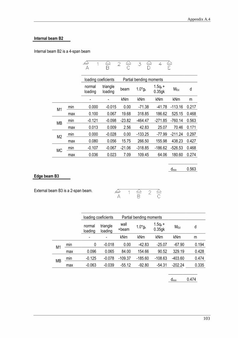
Appendix A.4
103
Internal beam B2
Internal beam B2 is a 4-span beam
loading coeficients Partial bending moments
normal loading
triangle loading
beam 1.0*gk 1.5qk + 0.35gk
MEd d
- - kNm kNm kNm kNm m
M1
min 0.000 -0.015 0.00 -71.38 -41.78 -113.16 0.217 max 0.100 0.067 19.68 318.85 186.62 525.15 0.468
MB min -0.121 -0.098 -23.82 -464.47 -271.85 -760.14 0.563
max 0.013 0.009 2.56 42.83 25.07 70.46 0.171
M2 min 0.000 -0.028 0.00 -133.25 -77.99 -211.24 0.297
max 0.080 0.056 15.75 266.50 155.98 438.23 0.427
MC min -0.107 -0.067 -21.06 -318.85 -186.62 -526.53 0.468
max 0.036 0.023 7.09 109.45 64.06 180.60 0.274
dmin 0.563
Edge beam B3
External beam B3 is a 2-span beam.
loading coeficients Partial bending moments
normal loading
triangle loading
wall +beam
1.0*gk 1.5qk + 0.35gk
MEd d
- - kNm kNm kNm kNm m
M1
min 0 -0.018 0.00 -42.83 -25.07 -67.90 0.194 max 0.096 0.065 84.00 154.66 90.52 329.19 0.428
MB min -0.125 -0.078 -109.37 -185.60 -108.63 -403.60 0.474
max -0.063 -0.039 -55.12 -92.80 -54.31 -202.24 0.335
dmin 0.474

Comparative analysis of RC slabs and columns
104
Internal beam B4
Internal beam B4 is a 2-span beam.
loading coeficients Partial bending moments
normal loading
triangle loading
beam 1.0*gk 1.5qk + 0.35gk
MEd d
- - kNm kNm kNm kNm m
M1 min 0 -0.018 0.00 -85.66 -50.14 -
135.80 0.238 max 0.096 0.065 18.90 309.33 181.05 509.27 0.461
MB
min -0.125 -0.078 -24.60 -371.20 -217.26 -
613.06 0.505
max -0.063 -0.039 -12.40 -185.60 -108.63 -
306.63 0.357
dmin 0.505 Dimensions of beams
h b Ac d
m m
m
B1 0.60 0.30 0.0018 0.560
B2 0.60 0.40 0.0024 0.560
B3 0.60 0.30 0.0018 0.560
B4 0.60 0.40 0.0024 0.560
Calculated reinforcement
Edge beam B1
Bottom reinforcement
MEd μ ω As,min As
kNm - - cm2 - cm2
M1 340.23 0.181 0.202 15.61 2Ø25+2Ø20 16.10
M2 281.24 0.150 0.164 12.62 2Ø25+2Ø16 13.84

Appendix A.4
105
Top reinforcement
MEd μ ω As,min As
kNm - - cm2 - cm2
MB -474.03 0.252 0.298 23.02 5Ø25 24.54
MC -346.36 0.184 0.206 15.93 2Ø25+2Ø20 16.10
Internal beam B2
Bottom reinforcement
MEd μ ω As,min As
kNm - - cm2 - cm2
M1 525.15 0.280 0.339 26.14 6Ø25 29.45
M2 438.23 0.233 0.271 20.94 5Ø25 24.54
Top reinforcement
MEd μ ω As,min As
kNm - - cm2 - cm2
MB -760.14 0.405 0.574 27.74 5Ø25 24.54
MC -526.53 0.280 0.340 16.41 2Ø25+2Ø20 16.10
Edge beam B3
Bottom reinforcement
MEd μ ω As,min As
kNm - - cm2 - cm2
M1 329.19 0.175 0.195 15.04 2Ø25+2Ø20 16.10
Top reinforcement
MEd μ ω As,min As
kNm - - cm2 - cm2
MB -403.60 0.215 0.246 19.00 4Ø25 19.63
Internal beam B4
Bottom reinforcement
MEd μ ω As,min As
kNm - - cm2 - cm2
M1 509.27 0.271 0.326 25.15 6Ø25 29.45

Comparative analysis of RC slabs and columns
106
Top reinforcement
MEd μ ω As,min As
kNm - - cm2 - cm2
MB -613.06 0.326 0.415 20.04 5Ø25 24.54
Shear
Shear forces in beam
Edge beam B1
Internal beam B2
type of loading
type of loading
normal triangle VEd
normal triangl
e VEd
- - kN
- - kN
VA min -0.053 -0.033 -18.57
VA min -0.053 -0.033 -30.69
0.00
0.00
V1B min -0.621 -0.326 -195.24
V1B min -0.621 -0.326 -315.02
max 0.014 0.009 5.01
max 0.014 0.009 8.31
V2B min -0.072 -0.045 -25.28
V2B min -0.072 -0.045 -41.82
max 0.603 0.314 188.65
max 0.603 0.314 304.02
V2C min -0.576 -0.298 -179.49
V2C min -0.576 -0.298 -288.98
max 0.107 0.067 37.62
max 0.107 0.067 62.24
V3C min -0.091 -0.057 -32.00
V3C min -0.091 -0.057 -52.94
max 0.591 0.307 184.62
max 0.591 0.307 297.41
coefficients taken from tables in [1]
coefficients taken from tables in [1]
Edge beam B3
Internal beam B4
type of loading
type of loading
normal triangle VEd
normal triangle VEd
- - kN
- - kN
VA min -0.05 -0.032 -17.83
VA min -0.05 -0.032 -29.59
max 0.45 0.219 135.15
max 0.45 0.219 215.61
V1B min -0.617 -0.323 -193.66
V1B min -0.617 -0.323 -312.33
max 0.017 0.011 6.11
max 0.017 0.011 10.15
V2B min -0.083 -0.053 -29.56
V2B min -0.083 -0.053 -49.03
max 0.583 0.303 182.18
max 0.583 0.303 293.50

Appendix A.4
107
Members not requiring design shear reinforcement
Beam fck d CRd,c k bw Asl ρl vmin VRd,c
VRd,c
min
MPa m - - m cm2 kPa kN kN
B1
30
0.560
0.12
19.907 0.30
3.77
2.2460 538.43 7.57 0.09
B2 0.560 19.907 0.40 1.6845 538.43 9.17 0.12
B3 0.560 19.907 0.30 2.2460 538.43 7.57 0.09
B4 0.560 19.907 0.40 1.6845 538.43 9.17 0.12
Members with vertical shear reinforcement
Shear resistance
Beam fywd αcw bw d z ν1 fcd cotΘ VRd,s VRd,max
MPa - m m m - MPa - kN kN
B1 434.78 1 0.30 0.56 0.5036 0.528 20 2.5 2201 550.08
B2 434.78 1 0.40 0.56 0.5036 0.528 20 2.5 2201 733.45
B3 434.78 1 0.30 0.56 0.5036 0.528 20 2.5 2201 550.08
B4 434.78 1 0.40 0.56 0.5036 0.528 20 2.5 2201 733.45
Calculation of shear reinforcement
Maximum longitudinal spacing of the stirrups
d α
cotα sl,max
m ° - m
0.42 90 0 0.315

Comparative analysis of RC slabs and columns
108
Minimal reinforcement
fck fyk ρw,min α bw Asw,min/s Asw/s
MPa MPa - ° m cm2/m cm2/m -
30 500 0.0009 90 0.30 2.63 4.02 Ø8 // 0.25 2 legs
30 500 0.0009 91 0.40 3.51 3.77 Ø6 // 0.30 4 legs
Shear reinforcement
fck αcw bw d z ν1 fcd cotΘ VRd,max
MPa - m m m - MPa - kN
30 1 0.30 0.56 0.504 0.528 20 2.5 550.08
Edge beam B1
support VEd Asw/s Assumed reinforcement
kN cm2/m cm2/m -
V1B -195.24 3.57 3.77 Ø6 // 0.30 4 legs
V2B 188.65 3.45 3.77 Ø6 // 0.30 4 legs
V2C -179.49 3.28 3.77 Ø6 // 0.30 4 legs
V3C 184.62 3.37 3.77 Ø6 // 0.30 4 legs
Internal beam B2
support VEd Asw/s Assumed reinforcement
kN cm2/m cm2/m -
V1B -315.02 5.76 8.04 Ø8 // 0.25 4 legs
V2B 304.02 5.55 8.04 Ø8 // 0.25 4 legs
V2C -288.98 5.28 8.04 Ø8 // 0.25 4 legs
V3C 297.41 5.43 8.04 Ø8 // 0.25 4 legs

Appendix A.4
109
Edge beam B3
support VEd Asw/s Assumed reinforcement
kN cm2/m cm2/m -
VA 135.15 2.47 3.77 Ø6 // 0.30 4 legs
V1B -193.66 3.54 3.77 Ø6 // 0.30 4 legs
V2B 182.18 3.33 3.77 Ø6 // 0.30 4 legs
Edge beam B4
support VEd Asw/s Assumed reinforcement
kN cm2/m cm2/m -
VA 215.61 3.94 4.02 Ø8 // 0.25 2 legs
V1B -312.33 5.71 8.04 Ø8 // 0.25 4 legs
V2B 293.50 5.36 8.04 Ø8 // 0.25 4 legs

Comparative analysis of RC slabs and columns
110
APPENDIX B
Table B.1: Slab with column heads – span 7.20m
unit quantity price per
unit price
Concrete C30/37
Column heads m
3 18.43 77.50 1428.48
Slab with normal height m3 73.73 77.50 5713.92
Edge beams m3 4.86 77.50 376.65
Steel A500
Ø6
kg 95.56 0.85 81.23
Ø8
kg 0.00 0.83 0.00
Ø10
kg 1707.09 0.80 1365.67
Ø12
kg 6035.32 0.78 4707.55
Ø16
kg 3448.66 0.77 2655.47
Ø20
kg 0.00 0.77 0.00
Formwork
Column heads m2 61.44 11.00 675.84
Slab with normal height m2 368.64 11.00 4055.04
Edge beams m2 61.2 11.00 673.20
Labour
Labor force - concrete pouring
euro/m3 97.02 4.50 436.59
Labor force - placing reinforcement (cutting, , bending, installing)
euro/kg 11286.64 0.17 1918.73
Total: 24088.38€

Appendix A.4
111
Table B.2: Slab with column heads – span 8.00m
unit quantity price per
unit price
Concrete C30/37
Column heads m
3 23.33 77.50 1807.92
Slab with normal height m3 90.74 77.50 7032.04
Edge beams m3 5.36 77.50 415.01
Steel A500
Ø6
kg 106.18 0.85 90.26
Ø8
kg 0.00 0.83 0.00
Ø10
kg 2096.43 0.80 1677.14
Ø12
kg 6499.06 0.78 5069.26
Ø16
kg 116.17 0.77 89.45
Ø20
kg 5099.09 0.77 3926.30
Formwork
Column heads m2 75.60 11.00 831.60
Slab with normal height m2 453.68 11.00 4990.48
Edge beams m2 68 11.00 748.00
Labour
Labor force - concrete pouring
euro/m3 119.42 4.50 537.39
Labor force - placing reinforcement (cutting, , bending, installing)
euro/kg 13916.93 0.17 2365.88
Total: 29580.73€

Comparative analysis of RC slabs and columns
112
Table B.3: Slab with column heads – span 8.80m
unit quantity price per
unit price
Concrete C30/37
Column heads m
3 28.80 77.50 2232.00
Slab with normal height m3 109.50 77.50 8486.56
Edge beams m3 5.85 77.50 453.38
Steel A500
Ø6
kg 116.80 0.85 99.28
Ø10
kg 2525.69 0.80 2020.55
Ø12
kg 5026.56 0.78 3920.72
Ø16
kg 6402.29 0.77 4929.77
Ø20
kg 7661.94 0.77 5899.69
Formwork
Column heads m2 93.12 11.00 1024.32
Slab with normal height m2 547.52 11.00 6022.72
Edge beams m2 80.96 11.00 890.56
Labour
Labor force - concrete pouring
euro/m3 144.15 4.50 648.69
Labor force - placing reinforcement (cutting, , bending, installing)
euro/kg 21733.29 0.17 3694.66
Total: 40322.90€

Appendix A.4
113
Table B.4: Waffle slab - span 7.20m
unit quantity price per
unit price
Concrete C30/37
Column heads
m3 32.77 77.50 2539.52
Slab with normal height m3 107.52 66.56 77.50
Edge beams m3 8.10 77.50 627.75
Steel A500
Ø6
kg 119.46 0.85 101.54
Ø8
kg 0.00 0.83 0.00
Ø10
kg 565.87 0.80 452.70
Ø12
kg 1150.37 0.78 897.29
Ø16
kg 2292.31 0.77 1765.08
Ø20
kg 296.94 0.77 228.65
Ø25 kg
Formwork
Slab
m2 468.72 11.00 5155.92
Molds returnable 0,8x0,8m2
m2 332.8 4.75 1580.80
Labour
Labor force - concrete pouring
euro/m3 107.43 4.50 483.43
Labor force - placing reinforcement (cutting, , bending, installing)
euro/kg 4424.94 0.17 752.24
Total: 19743.30€

Comparative analysis of RC slabs and columns
114
Table B.5: Waffle slab - span 8.00m
unit quantity price per
unit price
Concrete C30/37
Column heads
m3 32.77 77.50 2539.52
Slab with normal height m3 107.52 86.02 77.50
Edge beams m3 9.00 77.50 697.50
Steel A500
Ø6
kg 1242.50 0.85 1056.12
Ø8
kg 802.37 0.83 665.97
Ø10
kg 1179.80 0.80 943.84
Ø12
kg 392.06 0.78 305.81
Ø16
kg 4007.47 0.77 3085.75
Ø20
kg 395.08 0.77 304.21
Ø25 kg
Formwork
Slab
m2 572.00 11.00 6292.00
Molds returnable 0,8x0,8m2
m
2 537.6 430.08 4.75
Labour
Labor force - concrete pouring
euro/m
3 127.78 4.50 575.03
Labor force - placing reinforcement (cutting, , bending, installing)
euro/kg 8019.28 0.17 1363.28
Total: 26538.15€

Appendix A.4
115
Table B.6: Waffle slab - span 8.80m
unit quantity price per
unit price
Concrete C30/37
Column heads
m3 32.77 77.50 2539.52
Slab with normal height m3 107.52 107.52 77.50
Edge beams m3 9.90 77.50 767.25
Steel A500
Ø6
kg 1526.39 0.85 1297.43
Ø8
kg 395.38 0.83 328.16
Ø10
kg 1697.11 0.80 1357.69
Ø12
kg 790.65 0.78 616.71
Ø16
kg 3573.37 0.77 2751.49
Ø20
kg 500.12 0.77 385.09
Ø25 kg
Formwork
Slab
m2 685.52 11.00 7540.72
Molds returnable 0,8x0,8m2
m2 537.6 4.75 2553.60
Labour
Labor force - concrete pouring
euro/m3 150.19 4.50 675.85
Labor force - placing reinforcement (cutting, , bending, installing)
euro/kg 8483.01 0.17 1442.11
Total: 30850.42€

Comparative analysis of RC slabs and columns
116
Table B.7: Flat plate - span 5.60m
unit quantity price per
unit price
Concrete C30/37
Slab
m3 65.23 76.50 4990.00
Edge beams m3 5.60 77.50 434.00
Steel A500
Ø6
kg 74.33 0.85 63.18
Ø10
kg 891.93 0.80 713.55
Ø12
kg 554.06 0.78 432.17
Ø16
kg 1766.88 0.77 1360.50
Formwork
Slab
m2 250.88 11.00 2759.68
Edge beams m2 29.12 11.00 320.32
Labour
Labor force - concrete pouring
euro/m3 70.83 4.50 318.73
Labor force - placing reinforcement (cutting, , bending, installing)
euro/kg 3287.20 0.17 558.82
Total: 11950.95€
Table B.8: Flat plate - span 6.40m
unit quantity price per
unit price
Concrete C30/37
Slab
m3 98.30 76.50 7520.26
Edge beams m3 5.60 6.40 77.50
Steel A500
Ø6
kg 84.95 0.85 72.20
Ø10
kg 2729.37 0.80 2183.50
Ø12
kg 1847.25 0.78 1440.85
Ø16
kg 1429.61 0.77 1100.80
Formwork
Slab
m2 327.68 11.00 3604.48
Edge beams m2 29.12 33.28 11.00
Labour
Labor force - concrete pouring
euro/m3 104.70 4.50 471.17
Labor force - placing reinforcement (cutting, , bending, installing)
euro/kg 6091.18 0.17 1035.50
Total: 18290.84€

Appendix A.4
117
Table B.9: Flat plate - span 7.20m
unit quantity price per
unit price
Concrete C30/37
Slab
m3 136.86 76.50 10469.61
Edge beams m3 5.60 7.20 77.50
Steel A500
Ø6
kg 95.56 0.85 81.23
Ø8
kg 0.00 0.83 0.00
Ø10
kg 3430.82 0.80 2744.66
Ø12
kg 2180.74 0.78 1700.98
Ø16
kg 1894.66 0.77 1458.89
Ø20
kg 0.00 0.77 0.00
Formwork
Slab
m2 414.72 11.00 4561.92
Edge beams m2 37.44 11.00 411.84
Labour
Labor force - concrete pouring
euro/m3 144.06 4.50 648.26
Labor force - placing reinforcement (cutting, , bending, installing)
euro/kg 7601.79 0.17 1292.30
Total: 23927.68€
Table B.10: Slab with beams – span 7.20m
unit quantity price per
unit price
Concrete C30/37
Slab
m3 128.56 77.50 9963.65
Beams m3 5.85 77.50 453.10
Steel A500
Ø6
kg 281.30 0.85 239.10
Ø8
kg 7700.26 0.83 6391.22
Ø12
kg 0.00 0.78 0.00
Ø16
kg 200.03 0.77 154.02
Ø20
kg 585.96 0.77 451.19
Ø25 kg 4303.12 0.77 2514.00
Formwork
Slab
m2 414.72 11.00 4561.92
Beams m2 53.568 11.00 589.25
Labour
Labor force - concrete pouring
euro/m3 134.41 4.50 604.84
Labor force - placing reinforcement (cutting, , bending, installing)
euro/kg 8767.54 0.17 1490.48
Total: 27412.76€

Comparative analysis of RC slabs and columns
118
Table B.11: Slab with beams – span 6.40m
unit quantity price per
unit price
Concrete C30/37
Slab
m3 91.75 77.50 7110.66
Beams m3 3.94 77.50 305.54
Steel A500
Ø6
kg 250.04 0.85 212.53
Ø8
kg 4237.18 0.83 3516.86
Ø16
kg 350.06 0.77 269.54
Ø20
kg 0.00 0.77 0.00
Ø25 kg 4455.72 0.77 2514.00
Formwork
Slab
m2 327.68 11.00 3604.48
Beams m2 53.568 40.448 11.00
Labour
Labor force - concrete pouring
euro/m3 95.69 4.50 430.62
Labor force - placing reinforcement (cutting, , bending, installing)
euro/kg 4837.28 0.17 822.34
Total: 19231.49€
Table B.12: Slab with beams – span 5.60m
unit quantity price per
unit price
Concrete C30/37
Slab
m3 62.72 77.50 4860.80
Beams m3 3.94 2.74 77.50
Steel A500
Ø6
kg 0.00 0.85 0.00
Ø8
kg 3487.15 0.83 2894.34
Ø10
kg 0.00 0.80 0.00
Ø12
kg 0.00 0.78 0.00
Ø16
kg 136.13 0.77 104.82
Ø20
kg 1336.85 0.77 1029.38
Ø25 kg 1614.10 0.77 2514.00
Formwork
Slab
m2 250.88 11.00 2759.68
Beams m2 31.64 11.00 348.04
Labour
Labor force - concrete pouring
euro/m3 65.46 4.50 294.59
Labor force - placing reinforcement (cutting, , bending, installing)
euro/kg 4960.14 0.17 843.22
Total: 15861.53€

Appendix C
119
APPENDIX C
Table C.1: Cost of columns for the slabs with column heads – span 7.20m
Concrete C30/37
m
3 57.02 77.50 4419.36
Steel A500
kg 8553.60 0.78 6671.81
Labour
Labour force - concrete pouring
euro/m3 57.02 4.50 256.61
Labour force - placing reinforcement (cutting, , bending, installing)
euro/kg 8553.60 0.17 1454.11
Formwork
m
2 252.00 11.00 2772.00
Total: 15573.89€
Table C.2: Cost of columns for the slabs with column heads – span 8.00m
Concrete C30/37
m
3 65.05 77.50 5041.53
Steel A500
kg 9757.80 0.78 7611.08
Labour
Labour force - concrete pouring
euro/m3 65.05 4.50 292.73
Labour force - placing reinforcement (cutting, , bending, installing)
euro/kg 9757.80 0.17 1658.83
Formwork
m
2 267.84 11.00 2946.24
Total: 17550.41€

Comparative analysis of RC slabs and columns
120
Table C.3: Cost of columns for the slabs with column heads – span 8.80m
Concrete C30/37
m
3 76.62 77.50 5937.82
Steel A500
kg 11492.55 0.78 8964.19
Labour
Labour force - concrete pouring
euro/m3 76.62 4.50 344.78
Labour force - placing reinforcement (cutting, , bending, installing)
euro/kg 11492.55 0.17 1953.73
Formwork
m
2 291.60 11.00 3207.60
Total: 20408.12€
Table C.4: Cost of columns for the slabs with beams – span 5.60m
Concrete C30/37
m
3 62.32 77.50 4829.49
Steel A500
kg 9347.40 0.85 7945.29
Labour
Labour force - concrete pouring
euro/m3 62.32 4.50 280.42
Labour force - placing reinforcement (cutting, , bending, installing)
euro/kg 9347.40 0.17 1589.06
Formwork
m
2 263.52 11.00 2898.72
Total: 17542.98€
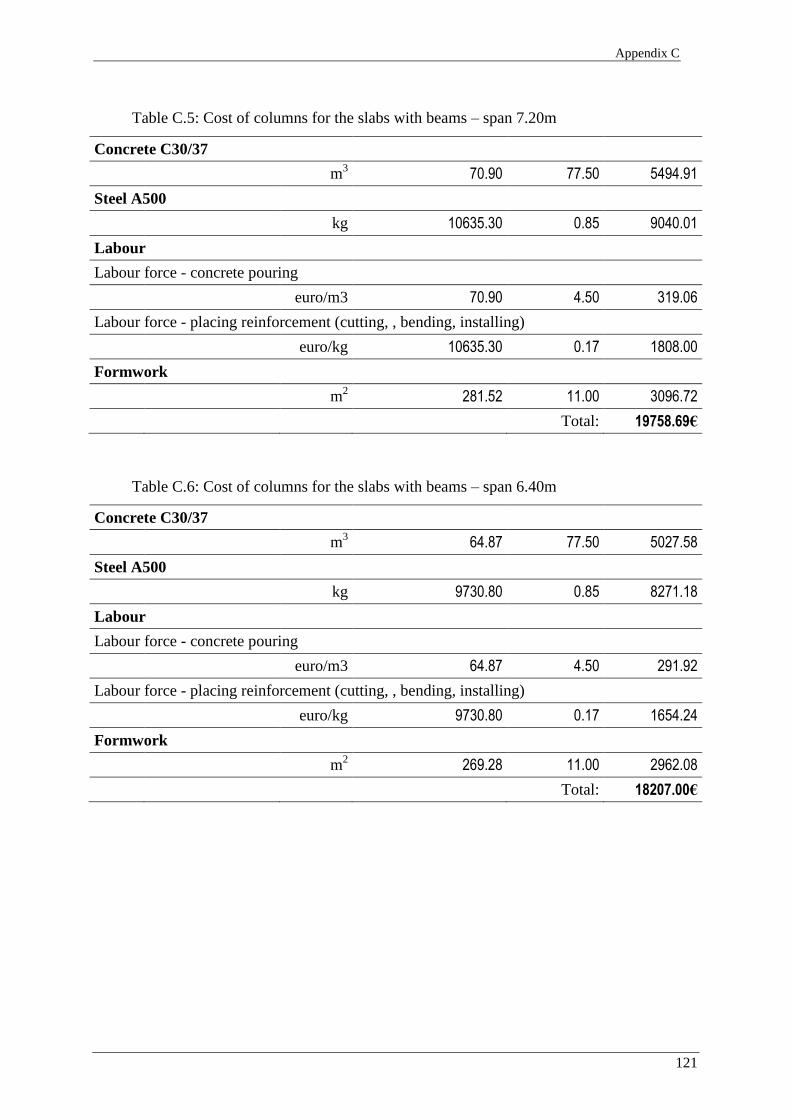
Appendix C
121
Table C.5: Cost of columns for the slabs with beams – span 7.20m
Concrete C30/37
m
3 70.90 77.50 5494.91
Steel A500
kg 10635.30 0.85 9040.01
Labour
Labour force - concrete pouring
euro/m3 70.90 4.50 319.06
Labour force - placing reinforcement (cutting, , bending, installing)
euro/kg 10635.30 0.17 1808.00
Formwork
m
2 281.52 11.00 3096.72
Total: 19758.69€
Table C.6: Cost of columns for the slabs with beams – span 6.40m
Concrete C30/37
m
3 64.87 77.50 5027.58
Steel A500
kg 9730.80 0.85 8271.18
Labour
Labour force - concrete pouring
euro/m3 64.87 4.50 291.92
Labour force - placing reinforcement (cutting, , bending, installing)
euro/kg 9730.80 0.17 1654.24
Formwork
m
2 269.28 11.00 2962.08
Total: 18207.00€

Comparative analysis of RC slabs and columns
122
Table C.7: Cost of columns for the flat plates – span 5.60m
Concrete C30/37
m
3 39.83 77.50 3087.14
Steel A500
kg 5975.10 0.78 4660.58
Labour
Labour force - concrete pouring
euro/m3 39.83 4.50 179.25
Labour force - placing reinforcement (cutting, , bending, installing)
euro/kg 5975.10 0.17 1015.77
Formwork
m
2 210.96 11.00 2320.56
Total: 11263.29€
Table C.8: Cost of columns for the flat plates – span 6.40m
Concrete C30/37
m
3 46.86 77.50 3631.88
Steel A500
kg 7029.45 0.78 5482.97
Labour
Labour force - concrete pouring
euro/m3 46.86 4.50 210.88
Labour force - placing reinforcement (cutting, , bending, installing)
euro/kg 7029.45 0.17 1195.01
Formwork
m
2 228.96 11.00 2518.56
Total: 13039.30€

Appendix C
123
Table C.9: Cost of columns for the flat plates – span 7.20m
Concrete C30/37
m
3 57.02 77.50 4419.36
Steel A500
kg 8553.60 0.78 6671.81
Labour
Labour force - concrete pouring
euro/m3 57.02 4.50 256.61
Labour force - placing reinforcement (cutting, , bending, installing)
euro/kg 8553.60 0.17 1454.11
Formwork
m
2 252.00 11.00 2772.00
Total: 15573.89€
Table C.10: Cost of columns for the waffle slabs – span 7.20m
Concrete C30/37
m
3 55.78 77.50 4323.11
Steel A500
kg 8367.30 0.78 6526.49
Labour
Labour force - concrete pouring
euro/m3 55.78 4.50 251.02
Labour force - placing reinforcement (cutting, , bending, installing)
euro/kg 8367.30 0.17 1422.44
Formwork
m
2 249.84 11.00 2748.24
Total: 15271.30€
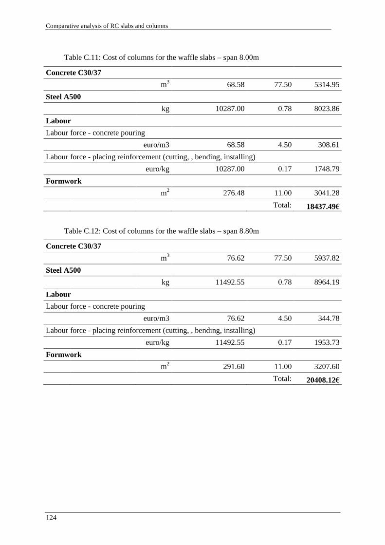
Comparative analysis of RC slabs and columns
124
Table C.11: Cost of columns for the waffle slabs – span 8.00m
Concrete C30/37
m
3 68.58 77.50 5314.95
Steel A500
kg 10287.00 0.78 8023.86
Labour
Labour force - concrete pouring
euro/m3 68.58 4.50 308.61
Labour force - placing reinforcement (cutting, , bending, installing)
euro/kg 10287.00 0.17 1748.79
Formwork
m
2 276.48 11.00 3041.28
Total: 18437.49€
Table C.12: Cost of columns for the waffle slabs – span 8.80m
Concrete C30/37
m
3 76.62 77.50 5937.82
Steel A500
kg 11492.55 0.78 8964.19
Labour
Labour force - concrete pouring
euro/m3 76.62 4.50 344.78
Labour force - placing reinforcement (cutting, , bending, installing)
euro/kg 11492.55 0.17 1953.73
Formwork
m
2 291.60 11.00 3207.60
Total: 20408.12€


![PERFORMANCE DESIGN OF REINFORCED CONCRETE SLABS · PDF filePERFORMANCE DESIGN OF REINFORCED CONCRETE SLABS USING ... concrete structures such as Abaqus [1], ... approach in the performance](https://img.pdfslide.net/doc/110x75/5a6fa32d7f8b9ab6538b47b0/performance-design-of-reinforced-concrete-slabs-nbsppdf-fileperformance.jpg)