Embed Size (px)
Citation preview
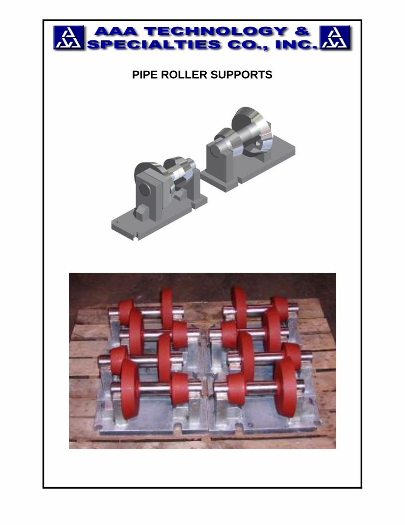
PIPE ROLLER SUPPORTS
Pipe Rollers
Introduction
AAA Technology & Specialties Co., Inc. has the Pipe Roller for yourevery pipeline application need. Pipe Rollers are used to allow thehorizontal expansion or contraction of your pipe due to moderate orextreme temperature variations.
The Pipe Rollers we manufacture are built to handle loads ranging fromlight duty to extra heavy duty. We have a variety of configurations thatcan be supported underneath or hung overhead; whether these arefixed or adjustable.
Our standard roller is manufactured from cast iron that can typicallyhandle up to 450 ⁰F. However our specialty rollers are manufactured inStainless Steel or even Chrome-Moly Alloy Steel to handle temperaturesof up to 1000⁰F.
These Pipe Rollers are manufactured in accordance to ANSI/ASMEB31.3, the MSS Standards SP-58 and SP-69, as well as the FederalSpecification WW-H-171 for Pipe Hangers and Supports.
Please call AAA Technology & Specialties Co., Inc. if you have any otherquestions or specifications. We are industry leaders in resolving yourStress Analysis and specialty roller design needs.
FIGURE 806 Contoured Cast Iron Pipe Roll 1
FIGURE 809 Clevis Roller Hanger 2
FIGURE 812 Two Rod Roll Type Hanger 3
FIGURE 815 Adjustable Support Roller 4
FIGURE 818 Alternate Adjustable Support Roller 5
FIGURE 821 Pipe Roller Chair 6
FIGURE 824 Cast Iron Pipe Roll 7
FIGURE 827 Pipe Roller & Stand 8
FIGURE 830 Adjustable Pipe Roller & Stand 9
FIGURE 833 Roller Support for- Large Diameter Pipe 10
INDEX
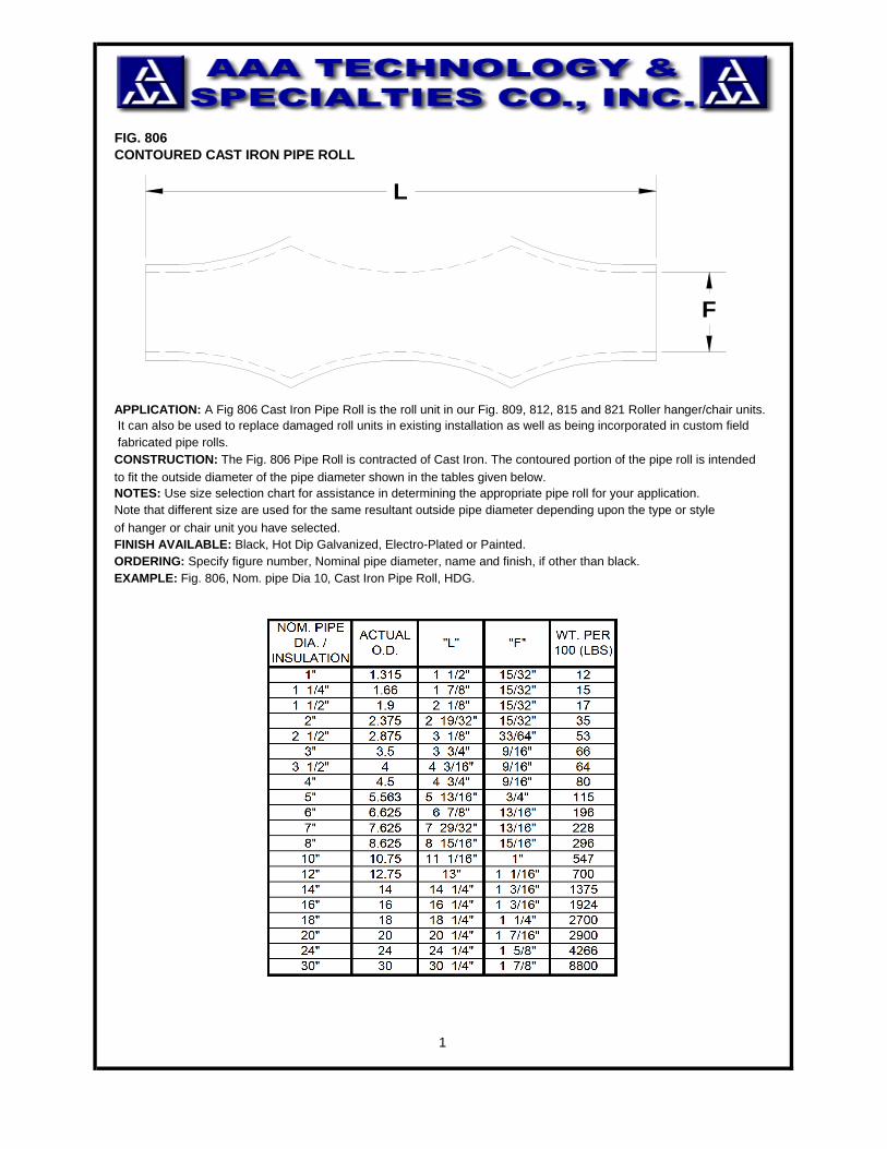
FIG. 806CONTOURED CAST IRON PIPE ROLL
to fit the outside diameter of the pipe diameter shown in the tables given below.
of hanger or chair unit you have selected.FINISH AVAILABLE: Black, Hot Dip Galvanized, Electro-Plated or Painted.ORDERING: Specify figure number, Nominal pipe diameter, name and finish, if other than black.EXAMPLE: Fig. 806, Nom. pipe Dia 10, Cast Iron Pipe Roll, HDG.
1
CONSTRUCTION: The Fig. 806 Pipe Roll is contracted of Cast Iron. The contoured portion of the pipe roll is intended
NOTES: Use size selection chart for assistance in determining the appropriate pipe roll for your application.Note that different size are used for the same resultant outside pipe diameter depending upon the type or style
APPLICATION: A Fig 806 Cast Iron Pipe Roll is the roll unit in our Fig. 809, 812, 815 and 821 Roller hanger/chair units. It can also be used to replace damaged roll units in existing installation as well as being incorporated in custom field fabricated pipe rolls.
F
L
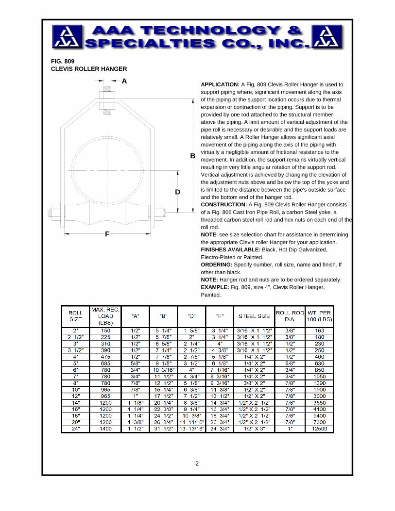
FIG. 809CLEVIS ROLLER HANGER
expansion or contraction of the piping. Support is to beprovided by one rod attached to the structural memberabove the piping. A limit amount of vertical adjustment of thepipe roll is necessary or desirable and the support loads arerelatively small. A Roller Hanger allows significant axialmovement of the piping along the axis of the piping withvirtually a negligible amount of frictional resistance to the movement. In addition, the support remains virtually verticalresulting in very little angular rotation of the support rod.Vertical adjustment is achieved by changing the elevation ofthe adjustment nuts above and below the top of the yoke andis limited to the distance between the pipe's outside surfaceand the bottom end of the hanger rod.CONSTRUCTION: A Fig. 809 Clevis Roller Hanger consistsof a Fig. 806 Cast Iron Pipe Roll, a carbon Steel yoke, athreaded carbon steel roll rod and hex nuts on each end of theroll rod.NOTE: see size selection chart for assistance in determiningthe appropriate Clevis roller Hanger for your application.FINISHES AVAILABLE: Black, Hot Dip Galvanized,Electro-Plated or Painted.ORDERING: Specify number, roll size, name and finish. If other than black.NOTE: Hanger rod and nuts are to be ordered separately.EXAMPLE: Fig. 809, size 4", Clevis Roller Hanger,Painted.
2
APPLICATION: A Fig, 809 Clevis Roller Hanger is used tosupport piping where; significant movement along the axis of the piping at the support location occurs due to thermal
D
B
F
A
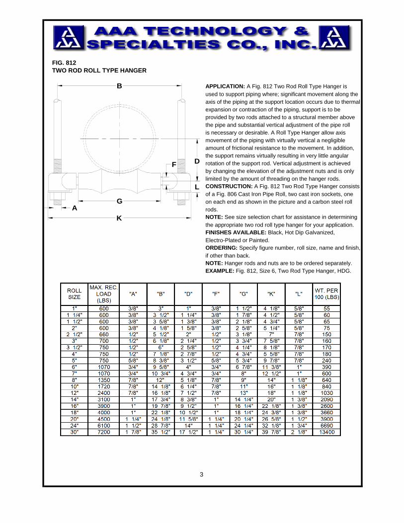
FIG. 812TWO ROD ROLL TYPE HANGER
APPLICATION: A Fig. 812 Two Rod Roll Type Hanger isused to support piping where; significant movement along theaxis of the piping at the support location occurs due to thermalexpansion or contraction of the piping, support is to beprovided by two rods attached to a structural member abovethe pipe and substantial vertical adjustment of the pipe rollis necessary or desirable. A Roll Type Hanger allow axis movement of the piping with virtually vertical a negligible amount of frictional resistance to the movement. In addition,the support remains virtually resulting in very little angularrotation of the support rod. Vertical adjustment is achievedby changing the elevation of the adjustment nuts and is onlylimited by the amount of threading on the hanger rods.CONSTRUCTION: A Fig. 812 Two Rod Type Hanger consistsof a Fig. 806 Cast Iron Pipe Roll, two cast iron sockets, one on each end as shown in the picture and a carbon steel roll rods.NOTE: See size selection chart for assistance in determiningthe appropriate two rod roll type hanger for your application.FINISHES AVAILABLE: Black, Hot Dip Galvanized, Electro-Plated or Painted.ORDERING: Specify figure number, roll size, name and finish,if other than back. NOTE: Hanger rods and nuts are to be ordered separately.EXAMPLE: Fig. 812, Size 6, Two Rod Type Hanger, HDG.
3
A
B
G
L
D
K
F
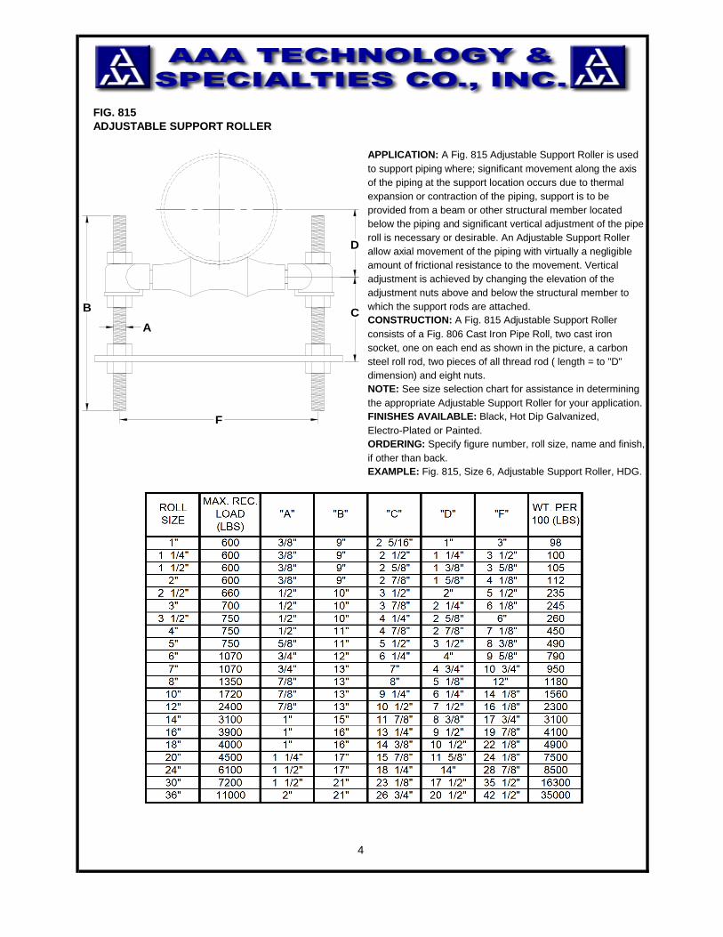
FIG. 815ADJUSTABLE SUPPORT ROLLER
APPLICATION: A Fig. 815 Adjustable Support Roller is usedto support piping where; significant movement along the axisof the piping at the support location occurs due to thermalexpansion or contraction of the piping, support is to beprovided from a beam or other structural member locatedbelow the piping and significant vertical adjustment of the piperoll is necessary or desirable. An Adjustable Support Rollerallow axial movement of the piping with virtually a negligibleamount of frictional resistance to the movement. Verticaladjustment is achieved by changing the elevation of the adjustment nuts above and below the structural member to which the support rods are attached.CONSTRUCTION: A Fig. 815 Adjustable Support Roller consists of a Fig. 806 Cast Iron Pipe Roll, two cast ironsocket, one on each end as shown in the picture, a carbonsteel roll rod, two pieces of all thread rod ( length = to "D"dimension) and eight nuts.NOTE: See size selection chart for assistance in determiningthe appropriate Adjustable Support Roller for your application.FINISHES AVAILABLE: Black, Hot Dip Galvanized, Electro-Plated or Painted.ORDERING: Specify figure number, roll size, name and finish,if other than back. EXAMPLE: Fig. 815, Size 6, Adjustable Support Roller, HDG.
4
D
C
F
A
B
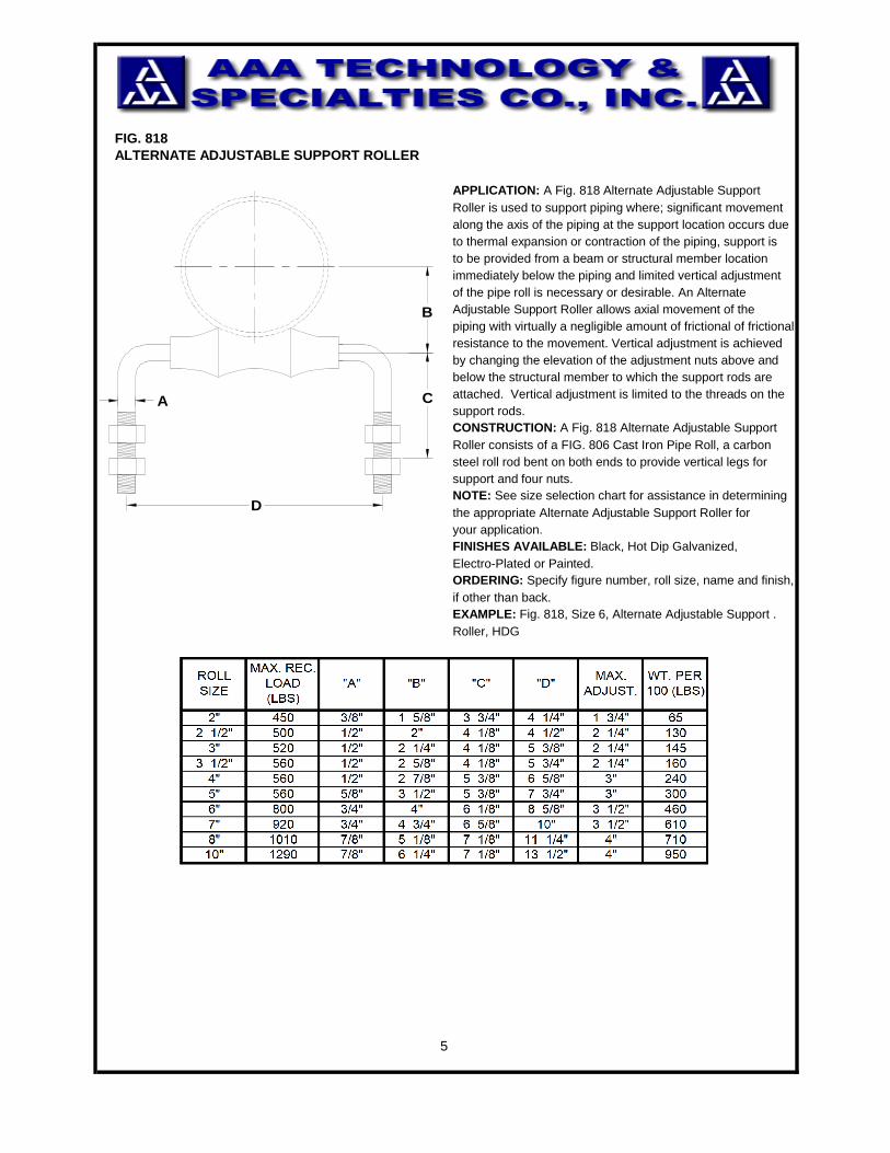
FIG. 818ALTERNATE ADJUSTABLE SUPPORT ROLLER
APPLICATION: A Fig. 818 Alternate Adjustable SupportRoller is used to support piping where; significant movementalong the axis of the piping at the support location occurs dueto thermal expansion or contraction of the piping, support isto be provided from a beam or structural member location immediately below the piping and limited vertical adjustmentof the pipe roll is necessary or desirable. An AlternateAdjustable Support Roller allows axial movement of the piping with virtually a negligible amount of frictional of frictionalresistance to the movement. Vertical adjustment is achievedby changing the elevation of the adjustment nuts above and below the structural member to which the support rods areattached. Vertical adjustment is limited to the threads on thesupport rods.CONSTRUCTION: A Fig. 818 Alternate Adjustable SupportRoller consists of a FIG. 806 Cast Iron Pipe Roll, a carbonsteel roll rod bent on both ends to provide vertical legs forsupport and four nuts.NOTE: See size selection chart for assistance in determiningthe appropriate Alternate Adjustable Support Roller for your application.FINISHES AVAILABLE: Black, Hot Dip Galvanized, Electro-Plated or Painted.ORDERING: Specify figure number, roll size, name and finish,if other than back. EXAMPLE: Fig. 818, Size 6, Alternate Adjustable Support .Roller, HDG
5
B
CA
D
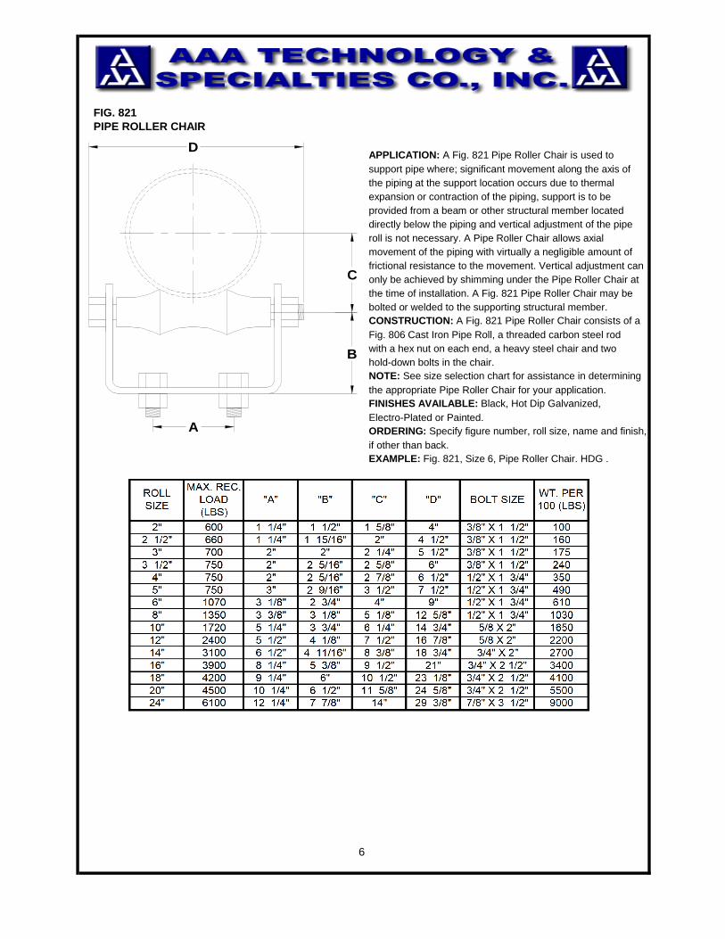
FIG. 821PIPE ROLLER CHAIR
APPLICATION: A Fig. 821 Pipe Roller Chair is used to support pipe where; significant movement along the axis ofthe piping at the support location occurs due to thermalexpansion or contraction of the piping, support is to be provided from a beam or other structural member located directly below the piping and vertical adjustment of the piperoll is not necessary. A Pipe Roller Chair allows axial movement of the piping with virtually a negligible amount offrictional resistance to the movement. Vertical adjustment canonly be achieved by shimming under the Pipe Roller Chair atthe time of installation. A Fig. 821 Pipe Roller Chair may bebolted or welded to the supporting structural member.CONSTRUCTION: A Fig. 821 Pipe Roller Chair consists of aFig. 806 Cast Iron Pipe Roll, a threaded carbon steel rod with a hex nut on each end, a heavy steel chair and two hold-down bolts in the chair.NOTE: See size selection chart for assistance in determiningthe appropriate Pipe Roller Chair for your application. FINISHES AVAILABLE: Black, Hot Dip Galvanized, Electro-Plated or Painted.ORDERING: Specify figure number, roll size, name and finish,if other than back. EXAMPLE: Fig. 821, Size 6, Pipe Roller Chair. HDG .
6
A
C
B
D
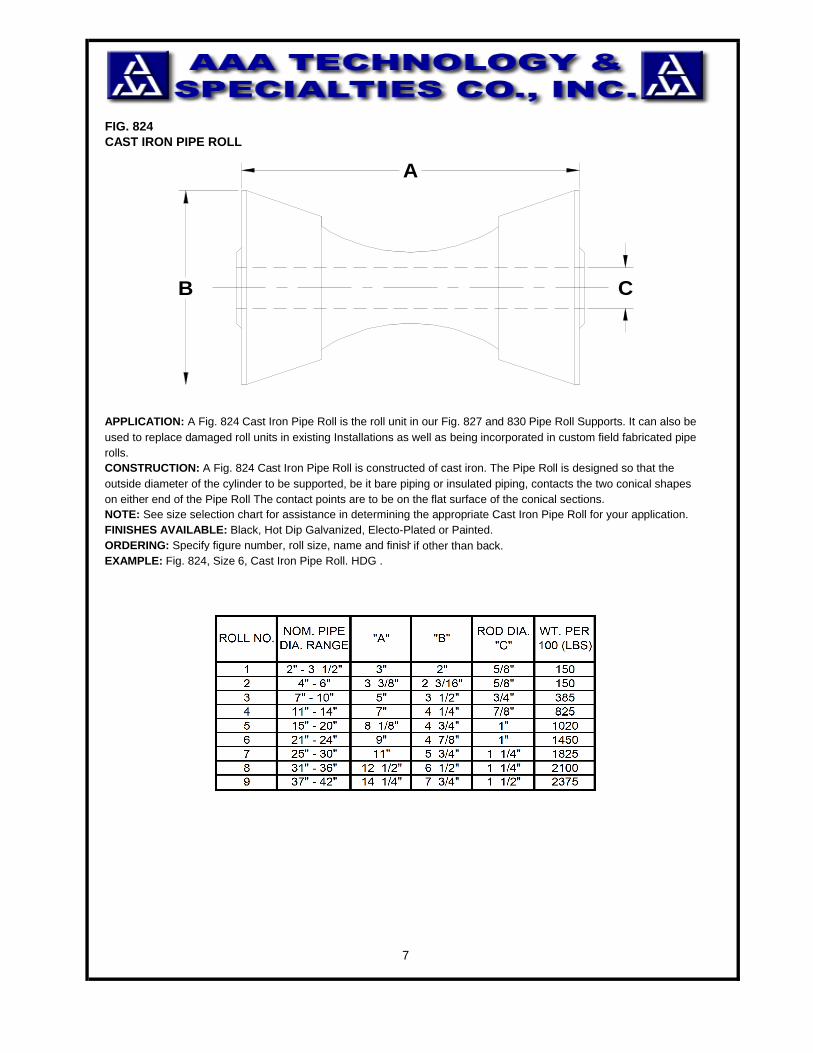
FIG. 824CAST IRON PIPE ROLL
APPLICATION: A Fig. 824 Cast Iron Pipe Roll is the roll unit in our Fig. 827 and 830 Pipe Roll Supports. It can also be used to replace damaged roll units in existing Installations as well as being incorporated in custom field fabricated pipe rolls. CONSTRUCTION: A Fig. 824 Cast Iron Pipe Roll is constructed of cast iron. The Pipe Roll is designed so that the outside diameter of the cylinder to be supported, be it bare piping or insulated piping, contacts the two conical shapeson either end of the Pipe Roll The contact points are to be on the flat surface of the conical sections.NOTE: See size selection chart for assistance in determining the appropriate Cast Iron Pipe Roll for your application.FINISHES AVAILABLE: Black, Hot Dip Galvanized, Electo-Plated or Painted. ORDERING: Specify figure number, roll size, name and finish,if other than back. EXAMPLE: Fig. 824, Size 6, Cast Iron Pipe Roll. HDG .
7
B C
A
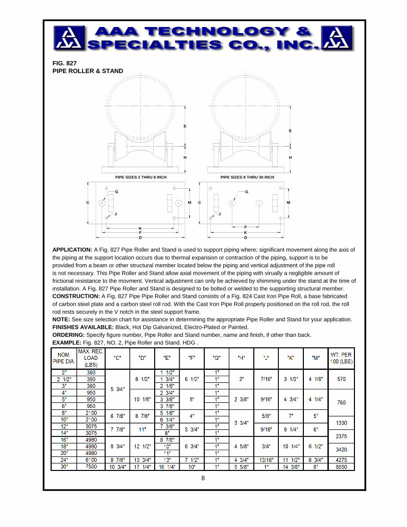
FIG. 827PIPE ROLLER & STAND
APPLICATION: A Fig. 827 Pipe Roller and Stand is used to support piping where; significant movement along the axis ofthe piping at the support location occurs due to thermal expansion or contraction of the piping, support is to be provided from a beam or other structural member located below the piping and vertical adjustment of the pipe roll is not necessary. This Pipe Roller and Stand allow axial movement of the piping with virually a negligible amount offrictional resistance to the movment. Vertical adjustment can only be achieved by shimming under the stand at the time ofinstallation. A Fig. 827 Pipe Roller and Stand is designed to be bolted or welded to the supporting structural member. CONSTRUCTION: A Fig. 827 Pipe Pipe Roller and Stand consists of a Fig. 824 Cast Iron Pipe Roll, a base fabricated of carbon steel plate and a carbon steel roll rod. With the Cast Iron Pipe Roll properly positioned on the roll rod, the roll rod rests securely in the V notch in the steel support frame.NOTE: See size selection chart for assistance in determining the appropriate Pipe Roller and Stand for your application. FINISHES AVAILABLE: Black, Hot Dip Galvanized, Electro-Plated or Painted.ORDERING: Specify figure number, Pipe Roller and Stand number, name and finish, if other than back. EXAMPLE: Fig. 827, NO. 2, Pipe Roller and Stand. HDG .
8
H
E
PIPE SIZES 2 THRU 8 INCH
H
E
PIPE SIZES 8 THRU 30 INCH
MC
F
KD
MC
KFD
J
G
J
G
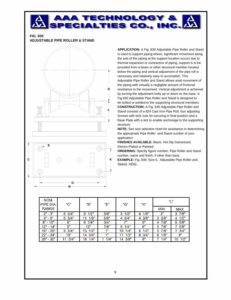
FIG. 830ADJUSTABLE PIPE ROLLER & STAND
APPLICATION: A Fig. 830 Adjustable Pipe Roller and Standis used to support piping where; significant movement alongthe axis of the piping at the support location occurs due tothermal expansion or contraction of piping, support is to beprovided from a beam or other structural member locatedbelow the piping and vertical adjustment of the pipe roll isnecessary and relatively easy to accomplish. This Adjustable Pipe Roller and Stand allows axial movement ofthe piping with virtually a negligible amount of frictional resistance to the movement. Vertical adjustment is achievedby turning the adjustment bolts up or down on the base. A Fig.830 Adjustable Pipe Roller and Stand is designed tobe bolted or welded to the supporting structural members.CONSTRUCTION: A Fig. 830 Adjustable Pipe Roller and Stand consists of a 824 Cast Iron Pipe Roll, four adjustingScrews with lock nuts for securing in final position and a Base Plate with a slot to enable anchorage to the supportingstructure.NOTE: See size selection chart for assistance in determiningthe appropriate Pipe Roller and Stand number of your .applicationFINISHES AVAILABLE: Black, Hot Dip Galvanized, Electro-Plated or Painted.ORDERING: Specify figure number, Pipe Roller and Standnumber, name and finish, if other than back. EXAMPLE: Fig. 830, Size 6, Adjustable Pipe Roller and Stand. HDG .
9
E
L
D
K
GB
C
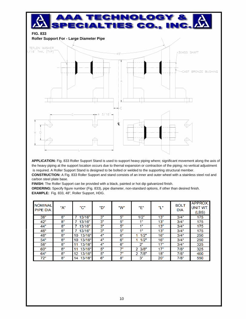
FIG. 833Roller Support For - Large Diameter Pipe
APPLICATION: Fig. 833 Roller Support Stand is used to support heavy piping where; significant movement along the axis of the heavy piping at the support location occurs due to thernal expansion or contraction of the piping; no vertical adjustment is required. A Roller Support Stand is designed to be bolted or welded to the supporting structural member.CONSTRUCTION: A Fig. 833 Roller Support and stand consists of an inner and outer wheel with a stainless steel rod and carbon steel plate base.FINISH: The Roller Support can be provided with a black, painted or hot dip galvanized finish.ORDERING: Specify figure number (Fig. 833), pipe diameter, non-standard options, if other than desired finish.EXAMPLE: Fig. 833, 48", Roller Support, HDG.
10
CL