Embed Size (px)
Citation preview
Fact File No 1
PIPELINE CORROSION RISKS ASSOCIATED WITH AC
VOLTAGES
Cathodic Protection Co Ltd
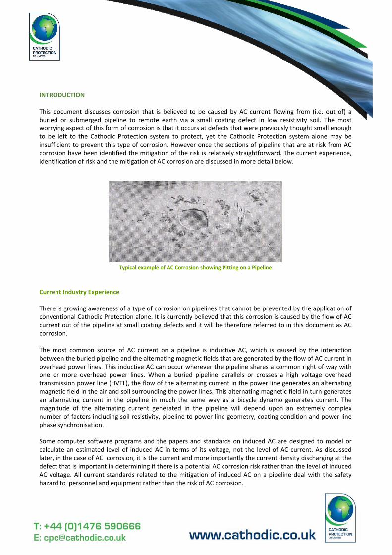
INTRODUCTION
This document discusses corrosion that is believed to be caused by AC current flowing from (i.e. out of) aburied or submerged pipeline to remote earth via a small coating defect in low resistivity soil. The mostworrying aspect of this form of corrosion is that it occurs at defects that were previously thought small enoughto be left to the Cathodic Protection system to protect, yet the Cathodic Protection system alone may beinsufficient to prevent this type of corrosion. However once the sections of pipeline that are at risk from ACcorrosion have been identified the mitigation of the risk is relatively straightforward. The current experience,identification of risk and the mitigation of AC corrosion are discussed in more detail below.
Typical example of AC Corrosion showing Pitting on a Pipeline
Current Industry Experience
There is growing awareness of a type of corrosion on pipelines that cannot be prevented by the application ofconventional Cathodic Protection alone. It is currently believed that this corrosion is caused by the flow of ACcurrent out of the pipeline at small coating defects and it will be therefore referred to in this document as ACcorrosion.
The most common source of AC current on a pipeline is inductive AC, which is caused by the interactionbetween the buried pipeline and the alternating magnetic fields that are generated by the flow of AC current inoverhead power lines. This inductive AC can occur wherever the pipeline shares a common right of way withone or more overhead power lines. When a buried pipeline parallels or crosses a high voltage overheadtransmission power line (HVTL), the flow of the alternating current in the power line generates an alternatingmagnetic field in the air and soil surrounding the power lines. This alternating magnetic field in turn generatesan alternating current in the pipeline in much the same way as a bicycle dynamo generates current. Themagnitude of the alternating current generated in the pipeline will depend upon an extremely complexnumber of factors including soil resistivity, pipeline to power line geometry, coating condition and power linephase synchronisation.
Some computer software programs and the papers and standards on induced AC are designed to model orcalculate an estimated level of induced AC in terms of its voltage, not the level of AC current. As discussedlater, in the case of AC corrosion, it is the current and more importantly the current density discharging at thedefect that is important in determining if there is a potential AC corrosion risk rather than the level of inducedAC voltage. All current standards related to the mitigation of induced AC on a pipeline deal with the safetyhazard to personnel and equipment rather than the risk of AC corrosion.
Research in Germany, North America and the UK indicates that AC corrosion is very dependent upon thefollowing factors:
A source of AC current on the line.Small coating defects in the pipeline coating.Low soil resistivity at these defects.High AC current density at the defects.
As stated above the most common source of AC current on a pipeline is caused by the pipeline paralleling orcrossing an overhead power line, which results in the inductive generation of AC on the pipeline. Other sourcesinclude AC rail traction and possibly the AC ripple generated by the Transformer Rectifier units of the CPsystem itself.
The size of the coating defect appears to be very important as well. The exact mechanism of AC corrosion isnot fully understood and more research is required, however it appears that the optimum size of defect is inthe area of 1cm2. lt is possible that this is related to the defect‘s ability to pass current and the resultingcurrent density being passed. It seems that if the defects are large the AC current can pass to earth withoutcausing corrosion whilst if the defect is too small the AC current takes an alternative (lower resistance) route.As with any form of corrosion the lower the circuit resistance the more corrosion and this is true for ACcorrosion. AC corrosion occurs when the AC current goes to remote earth and it is more likely to do this atdefects in contact with low resistivity soil.
Research indicates that the following current densities appear to be important for AC corrosion:
20 A/m2 ‐ Little possibility of corrosion, monitor the situation but no further action required;
10O A/m2 ‐ AC corrosion is becoming a possibility, consideration should be given to mitigation measures.
150 A/m2 ‐ AC corrosion is now a distinct possibility, mitigation measures should be put in place.
lt has been found that AC current densities high enough to cause AC corrosion can occur with AC voltages aslow as 4 Vac and even lower and that the controlling factors are the size of the defect and the soil resistivity.Therefore as stated above remember that the stated limit of 15 Vac is with respect to safety issues and notassociated with AC corrosion.
To help explain this better, a number of examples are discussed below:
Imagine a large coating defect in high resistivity soil and that there is a fixed level of AC current flowing on thepipeline, say 1 A AC. At such a defect the limiting factor to the amount of current that will flow of the pipelineat this point is the soil resistivity, i.e. the high soil resistivity prevents the AC current from flowing off thepipeline thereby keeping the current density at the defect low. Therefore the risk of AC corrosion at such adefect is low.
lmagine the same large coating defect in low resistivity soil with the same 1 A AC flowing on the pipeline. Thelarge surface area of the coating defect means that even though all of the AC current flows off the pipeline atthis point the current density is still low and therefore the risk of AC corrosion is low.
Assuming we have the same 1 A AC but that this time the coating defect is small and the soil resistivity is lowthen the risk of AC corrosion will be high. This is because the low soil resistivity represents a low resistancepath to remote earth that will be attractive to the AC current and it will try to leave the pipeline here. Whenthis is combined with a small coating defect, the current density becomes very high and the risk of ACcorrosion is proportionally higher.
Once again if we take the same 1 A AC but this time assume that it is a small coating defect in high resistivitysoil then the limiting factor to the flow of AC current to remote earth will be the soil resistivity. This means thaton a small coating defect the resistance at the interface between the steel and the soil will be almost infinitethereby limiting the current flow and hence current density to safe limits.
As discussed above research seems to indicate that there is an optimum size of coating defect, which will be atrisk from AC corrosion. lf the defect is much bigger than this the risk of AC corrosion is limited because thecurrent density decreases.
Much smaller than this and the AC corrosion risk also decreases probably because the boundary resistance toremote earth between the bare steel and the soil even through low resistivity soil approaches infinity and thislimits the flow of current to a safe level.
How do we identify AC Corrosion in the field?
The following procedure has been established:
Identify those areas of the pipeline where induced AC is likely to occur, i.e. parallelisms or crossings of HVTL.
Establish the true level of induced AC in the area(s) of concern. This is done by measuring the levels of inducedAC versus time over a period of time, for example over a minimum of seven days for twenty‐four hours a day.In this way the variation over a typical day during a typical week can be accurately assessed. There can besignificant variations in the levels of induced AC throughout the day and throughout the week that are causedby variations in the level of demand placed upon the power grid by electricity consumers. For exampleelectricity consumption is higher in the evenings when people are cooking and watching television than atother times of the day. Therefore the load on the power lines is higher and the induced AC is proportionallyincreased as well.
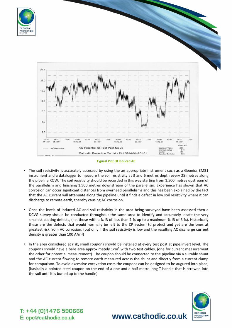
Typical Plot Of Induced AC
• The soil resistivity is accurately accessed by using the an appropriate instrument such as a Geonics EM31instrument and a datalogger to measure the soil resistivity at 3 and 6 metres depth every 25 metres alongthe pipeline ROW. The soil resistivity should be recorded in this way starting from 1,500 metres upstream ofthe parallelism and finishing 1,500 metres downstream of the parallelism. Experience has shown that ACcorrosion can occur significant distances from overhead parallelisms and this has been explained by the factthat the AC current will attenuate along the pipeline until it finds a defect in low soil resistivity where it candischarge to remote earth, thereby causing AC corrosion.
• Once the levels of induced AC and soil resistivity in the area being surveyed have been assessed then aDCVG survey should be conducted throughout the same area to identify and accurately locate the verysmallest coating defects, (i.e. those with a % lR of less than 1 % up to a maximum % IR of 3 %). Historicallythese are the defects that would normally be left to the CP system to protect and yet are the ones atgreatest risk from AC corrosion, (but only if the soil resistivity is low and the resulting AC discharge currentdensity is greater than 100 A/m2)
• ln the area considered at risk, small coupons should be installed at every test post at pipe invert level. Thecoupons should have a bare area approximately 1cm2 with two test cables, (one for current measurementthe other for potential measurement). The coupon should be connected to the pipeline via a suitable shuntand the AC current flowing to remote earth measured across the shunt and directly from a current clampfor comparison. To avoid excessive excavation costs the coupons can be designed to be augured into place,(basically a pointed steel coupon on the end of a one and a half metre long T‐handle that is screwed intothe soil until it is buried up to the handle).
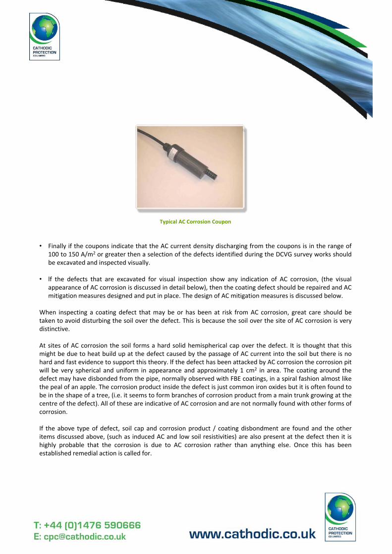
Typical AC Corrosion Coupon
• Finally if the coupons indicate that the AC current density discharging from the coupons is in the range of100 to 150 A/m2 or greater then a selection of the defects identified during the DCVG survey works shouldbe excavated and inspected visually.
• lf the defects that are excavated for visual inspection show any indication of AC corrosion, (the visualappearance of AC corrosion is discussed in detail below), then the coating defect should be repaired and ACmitigation measures designed and put in place. The design of AC mitigation measures is discussed below.
When inspecting a coating defect that may be or has been at risk from AC corrosion, great care should betaken to avoid disturbing the soil over the defect. This is because the soil over the site of AC corrosion is verydistinctive.
At sites of AC corrosion the soil forms a hard solid hemispherical cap over the defect. It is thought that thismight be due to heat build up at the defect caused by the passage of AC current into the soil but there is nohard and fast evidence to support this theory. lf the defect has been attacked by AC corrosion the corrosion pitwill be very spherical and uniform in appearance and approximately 1 cm2 in area. The coating around thedefect may have disbonded from the pipe, normally observed with FBE coatings, in a spiral fashion almost likethe peal of an apple. The corrosion product inside the defect is just common iron oxides but it is often found tobe in the shape of a tree, (i.e. it seems to form branches of corrosion product from a main trunk growing at thecentre of the defect). All of these are indicative of AC corrosion and are not normally found with other forms ofcorrosion.
If the above type of defect, soil cap and corrosion product / coating disbondment are found and the otheritems discussed above, (such as induced AC and low soil resistivities) are also present at the defect then it ishighly probable that the corrosion is due to AC corrosion rather than anything else. Once this has beenestablished remedial action is called for.
How is AC corrosion prevented?
Thankfully the mitigation of AC corrosion is relatively simple as it uses the same materials and techniques asthe mitigation of induced AC. If the induced AC and any other sources of AC on the pipeline can be removedthen the pipeline will no longer be at risk from AC corrosion. Having established that the pipeline is at risk, thatthere is induced AC and /or other sources and that there are defects of the correct size to propagate ACcorrosion then the following formula can be used to calculate the minimum level of AC voltage at which ACcorrosion will occur:
iac = 8.Vac / ρ.π.d
Where: iac = ac current density (Amps /m2)Vac = pipe ac voltage to remote earth (Volts AC)ρ = soil resistivity (Ohm.m)π = 3.142d = defect diameter of a circular defect with an area of 1 cm2
Example:
Assuming that we wish to calculate the AC potential required to generate a 100 A/m2discharge from a 1 cm2
defect in 10 Ohm.m (1,000 Ohm.cm) resistivity soil we would use the above formula as follows:
Vac = 100 x 10 x 3.142 x 0.113 / 8Vac = 4.4 Vac
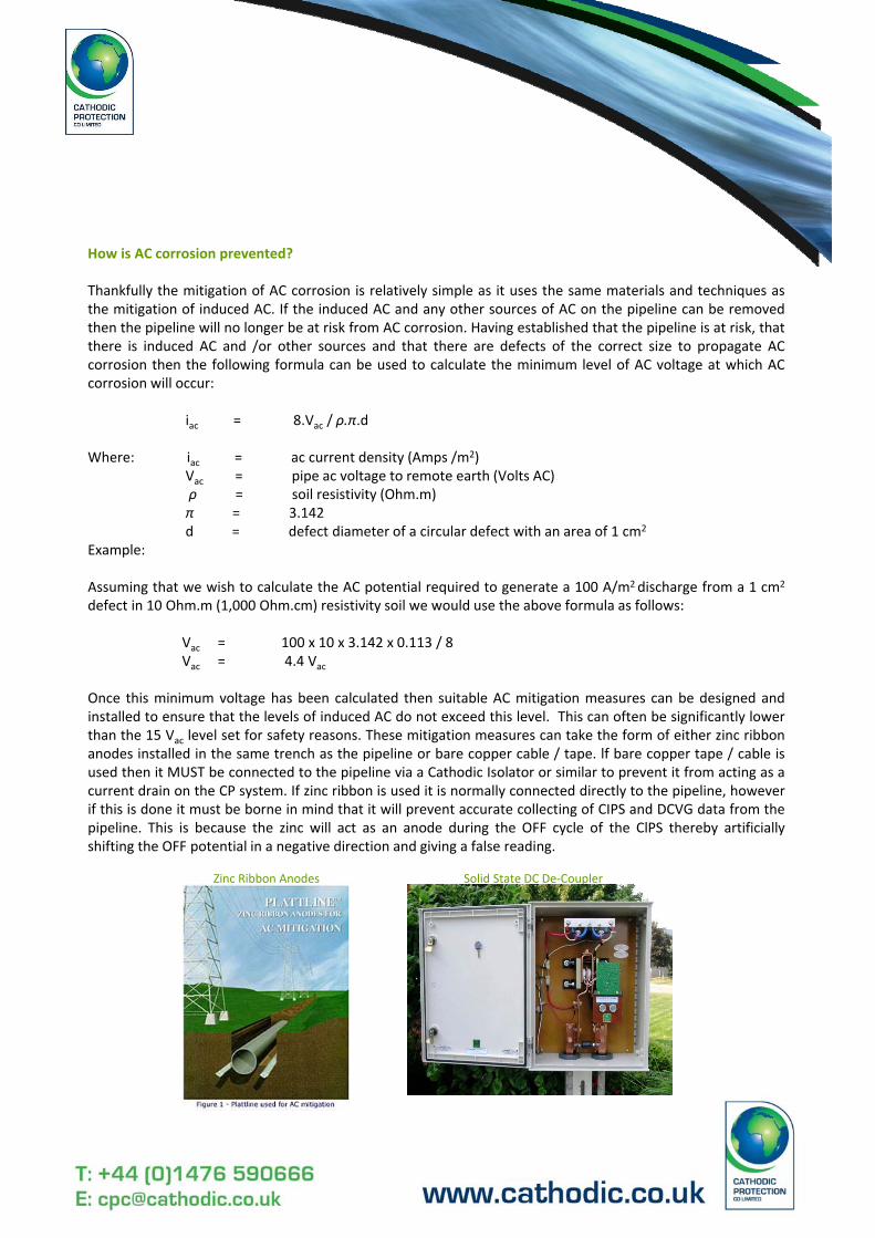
Once this minimum voltage has been calculated then suitable AC mitigation measures can be designed andinstalled to ensure that the levels of induced AC do not exceed this level. This can often be significantly lowerthan the 15 Vac level set for safety reasons. These mitigation measures can take the form of either zinc ribbonanodes installed in the same trench as the pipeline or bare copper cable / tape. lf bare copper tape / cable isused then it MUST be connected to the pipeline via a Cathodic Isolator or similar to prevent it from acting as acurrent drain on the CP system. If zinc ribbon is used it is normally connected directly to the pipeline, howeverif this is done it must be borne in mind that it will prevent accurate collecting of CIPS and DCVG data from thepipeline. This is because the zinc will act as an anode during the OFF cycle of the ClPS thereby artificiallyshifting the OFF potential in a negative direction and giving a false reading.
Zinc Ribbon Anodes Solid State DC De‐Coupler

In the case of DCVG survey works the zinc ribbon acts like a huge coating defect preventing the surveyor fromlocating the real defects. To avoid this zinc ribbon can be connected to the pipeline via a Cathodic lsolator orsimilar. To ensure that the above measures are effective permanent coupons should be installed along thesame section of pipeline where the mitigation measures are installed. These coupons should have a bare areaof approximately 1cm2, two cables and a suitably rated shunt.
lf the mitigation measures have been successful then the induced AC voltage should be lower than the levelcalculated above and more importantly the current density figure for AC current discharging at the couponsshould be significantly less than 100 A/m2. However it should be borne in mind that the levels of induced ACare time dependant and will vary with the load on the overhead power lines. Therefore the levels of inducedAC and AC current discharge at the coupons should be recorded for a minimum of seven days for twenty‐fourhours a day. If the induced AC voltage and Current density figures stay below the criteria discussed above thenthe mitigation measures can be considered to be successful. However they should be monitored routinelythroughout the life of the pipeline to ensure that any changes that might result in the pipeline being at riskagain from AC corrosion are immediately identified and corrected.