Embed Size (px)
Citation preview
Pipelining• Two forms of pipelining
– Instruction unit• overlap fetch-execute cycle so that multiple instructions are being processed
at the same time, each instruction in a different portion of the fetch-execute cycle
– Operation unit• overlap execution of ALU operations• only useful if execution takes > 1 cycle
– e.g., floating point operations
• We will concentrate mostly on instruction unit-level• Terms
– Stage – a portion of the pipeline that can accommodate one instruction, the length of the pipeline is in stages
– Throughput – how often the pipeline delivers a completed instruction, our goal is 1.0 (or less!), that is, one instruction leaves the pipeline at the end of each clock cycle (this would give us an ideal CPI of 1.0)
– Stall – the need to postpone instructions from moving down the pipeline, stalls are caused by hazards
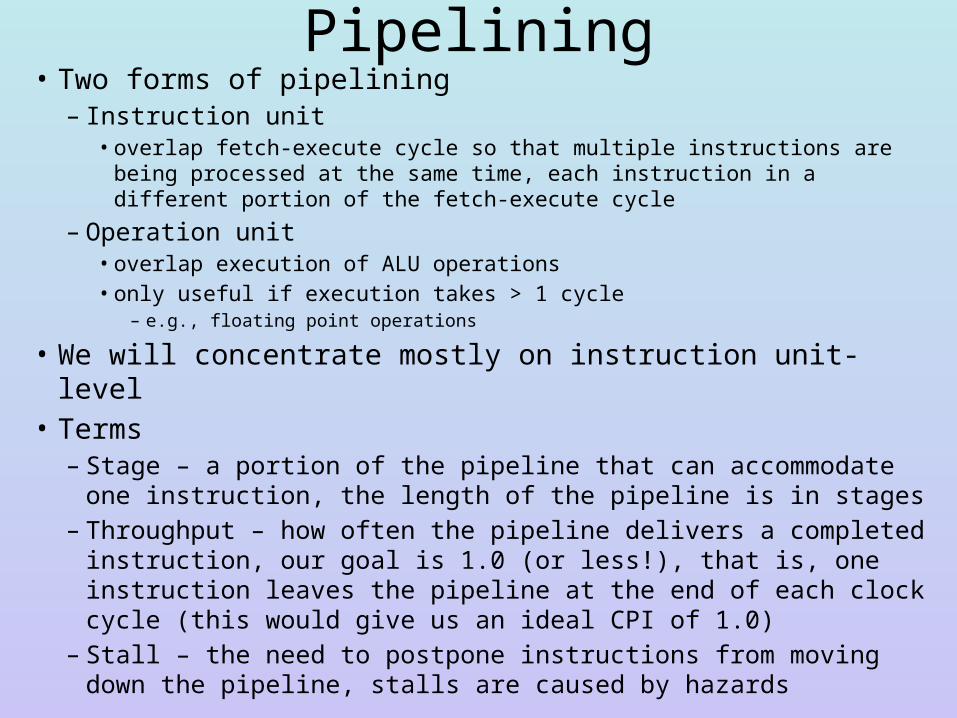
From Non-pipelined to Pipelined
We add latches betweenstages to control whenthe instruction can moveinto the new pipe stage
Latches will also containlogic which will be used tohandle forwarding and insertstalls
Latches are registers,Denoted as IF/ID.IRAnd ID/EX.A for example
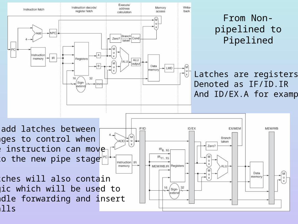
MIPS Pipeline• The MIPS pipeline is a 5-stage pipeline– Performance = (n + k – 1 + s) * overhead
• n = number of instructions• k = 5 (number of stages)• s = stalls, number of stalls inserted is based on the code• overhead = the pipeline latency, which primarily is the time
it takes for the logic in the latches to compute as well as extra time to open latches, etc
Problems with the Pipeline• Two instructions might try to alter the PC at the same time
– PC incremented in IF– A branch instruction in EX could alter the PC
• Two instructions could attempt to access memory at the same time– Instruction fetch in IF and data access in MEM– We will use two separate caches to avoid this problem (instruction
cache accessed by IF stage, data cache accessed by MEM stage)
• The stages differ in the time it takes to perform their operation – IF and MEM are the longest due to cache access time, so we have
to slow the clock speed down to this rate
• Hazards– Covered in a bit, these result in stalls which lengthens the CPI
from an ideal CPI of 1 to something larger (1 + stalls/instruction)
Pipelined vs Non-pipelined MIPS• Assume 1 ns (1 GHz) clock speed but the pipeline
accrues an added .2 ns overhead• Assume benchmark of – 40% ALU, 20% branches, 40% for loads and stores– CPI for unpipelined machine is 4 cycles for ALU and
branches and 5 for loads and stores
• How much faster is the pipelined machine assuming no stalls?– Non-pipelined machine has average CPI = .40 * 5 + .60 * 4
= 4.4– Pipelined machine has CPI = 1– Non-pipelined CPU time = 1 ns * 4.4 * IC– Pipelined CPU time = 1.2 ns * 1 * IC
• Pipelined machine is faster by 4.4 / 1.2 = 3.7
Another Example• For a non-pipelined version of MIPS, there is
no reason to tune each stage to the same time– Assume IF & MEM take 1 ns each, ID, WB take .7
ns and EX takes .8 ns– For the pipelined version, we set the system clock
speed at the longest stage, 1 ns, and assume an additional .2 ns overhead
• What is the speedup of our pipelined machine?– Non-pipelined machine executes 1 instruction n 1
+ .7 + .8 + 1 + .7 = 4.2 ns– Pipelined machine averages 1.2 ns per instruction– Speedup = 4.2 / 1.2 = 3.5
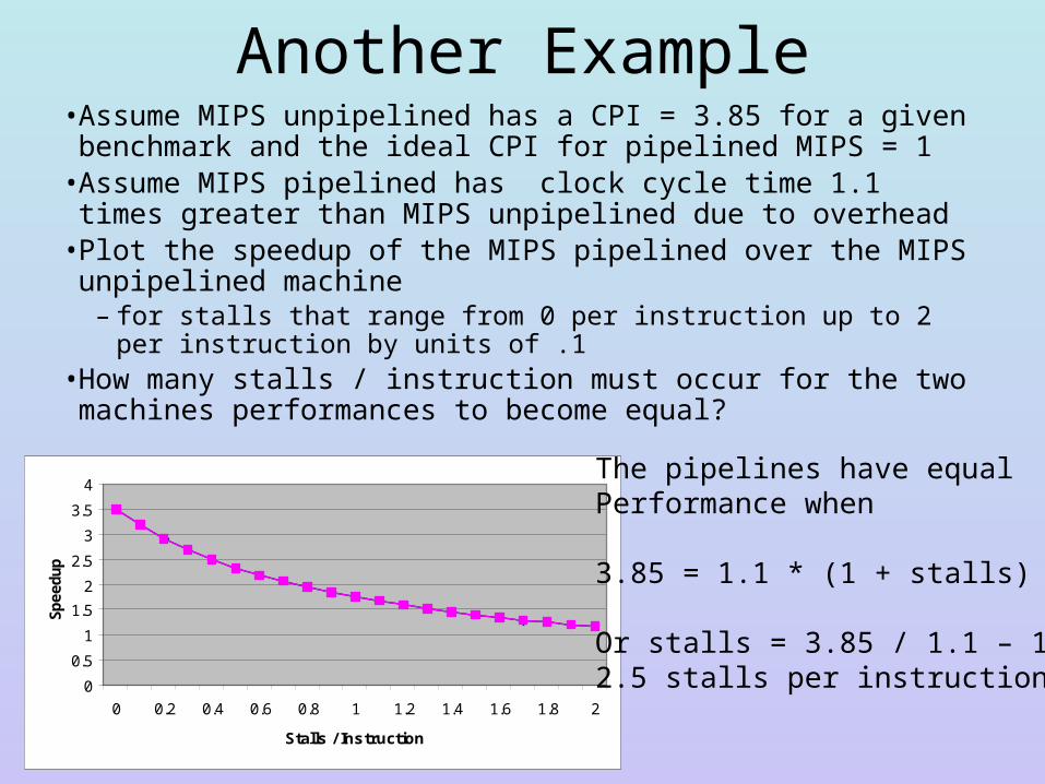
Another Example• Assume MIPS unpipelined has a CPI = 3.85 for a given benchmark
and the ideal CPI for pipelined MIPS = 1• Assume MIPS pipelined has clock cycle time 1.1 times greater than
MIPS unpipelined due to overhead• Plot the speedup of the MIPS pipelined over the MIPS unpipelined
machine – for stalls that range from 0 per instruction up to 2 per instruction by
units of .1• How many stalls / instruction must occur for the two machines
performances to become equal?
0
0.5
1
1.5
2
2.5
3
3.5
4
0 0.2 0.4 0.6 0.8 1 1.2 1.4 1.6 1.8 2
Stalls / Instruction
Sp
eed
up
The pipelines have equalPerformance when
3.85 = 1.1 * (1 + stalls)
Or stalls = 3.85 / 1.1 – 1 = 2.5 stalls per instruction
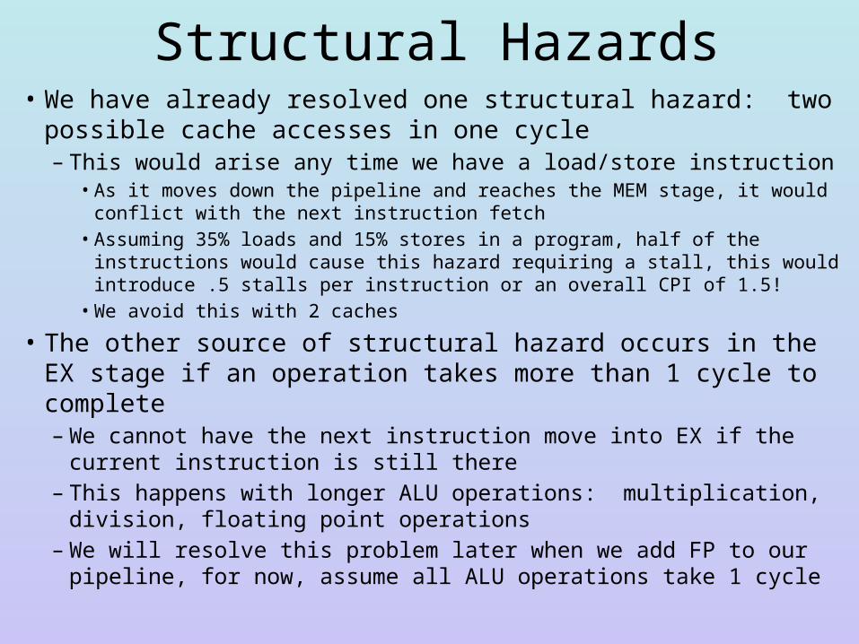
Structural Hazards• We have already resolved one structural hazard: two possible
cache accesses in one cycle– This would arise any time we have a load/store instruction
• As it moves down the pipeline and reaches the MEM stage, it would conflict with the next instruction fetch
• Assuming 35% loads and 15% stores in a program, half of the instructions would cause this hazard requiring a stall, this would introduce .5 stalls per instruction or an overall CPI of 1.5!
• We avoid this with 2 caches
• The other source of structural hazard occurs in the EX stage if an operation takes more than 1 cycle to complete– We cannot have the next instruction move into EX if the current
instruction is still there– This happens with longer ALU operations: multiplication, division,
floating point operations– We will resolve this problem later when we add FP to our pipeline, for
now, assume all ALU operations take 1 cycle
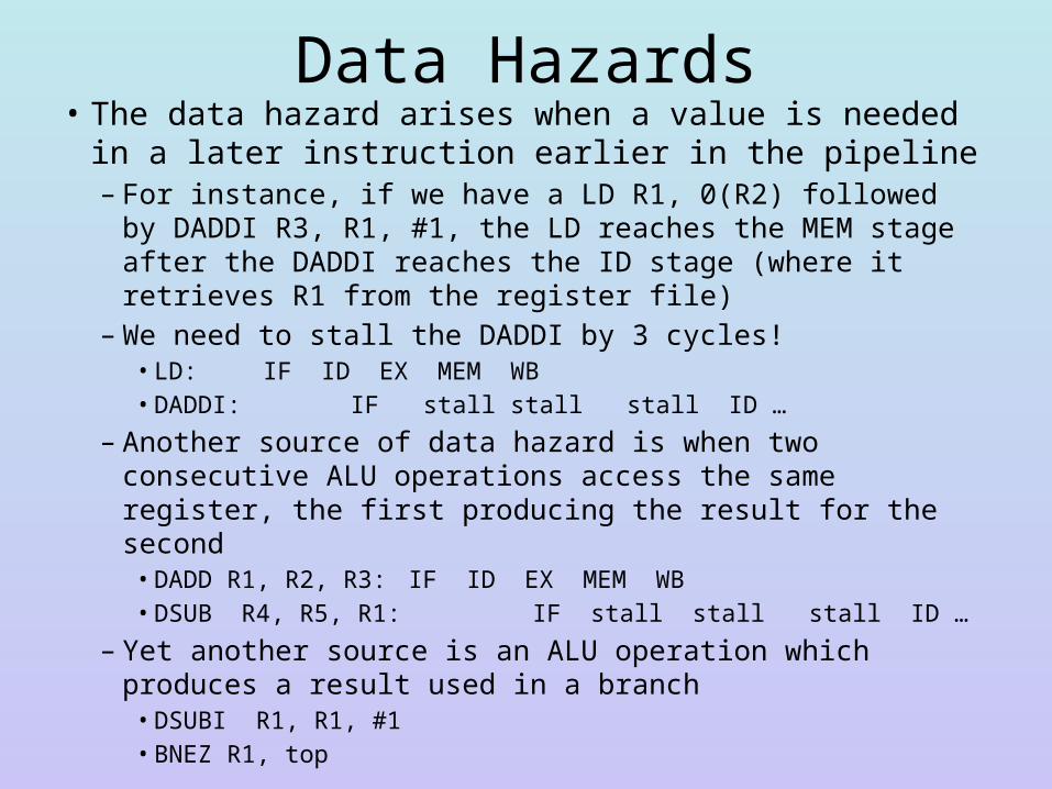
Data Hazards• The data hazard arises when a value is needed in a later
instruction earlier in the pipeline– For instance, if we have a LD R1, 0(R2) followed by DADDI
R3, R1, #1, the LD reaches the MEM stage after the DADDI reaches the ID stage (where it retrieves R1 from the register file)
– We need to stall the DADDI by 3 cycles!• LD: IF ID EX MEM WB• DADDI: IF stall stall stall ID …
– Another source of data hazard is when two consecutive ALU operations access the same register, the first producing the result for the second• DADD R1, R2, R3: IF ID EX MEM WB• DSUB R4, R5, R1: IF stall stall stall ID …
– Yet another source is an ALU operation which produces a result used in a branch• DSUBI R1, R1, #1• BNEZ R1, top
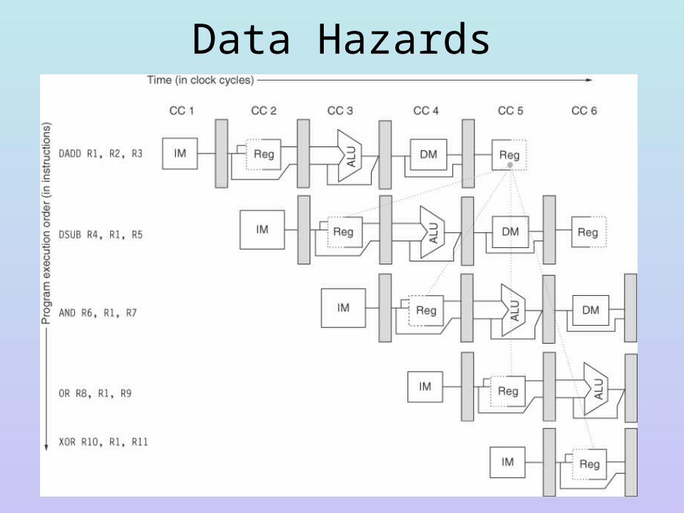
Data Hazards
Solutions• We will implement 3 solutions to data hazards– First, we will only access registers in the first half of the
cycle in WB and the second half of the cycle in ID• this permits an instruction to place a result in the register file
and in the same cycle another instruction can read the same register to get the new value
– Second, we will implement forwarding (covered in the next slide) • this will shunt a value directly from the ALU as output directly
into the ALU as input• this will shunt a value received from memory directly into the
ALU as input or directly back to memory
– Third, we will let the compiler fill any remaining stalls with neutral instructions, this is called compiler scheduling
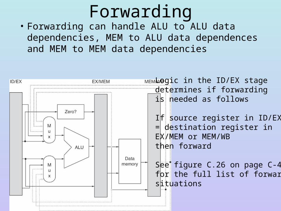
Forwarding• Forwarding can handle ALU to ALU data dependencies,
MEM to ALU data dependences and MEM to MEM data dependencies
Logic in the ID/EX stagedetermines if forwardingis needed as follows
If source register in ID/EX = destination register in EX/MEM or MEM/WBthen forward
See figure C.26 on page C-40for the full list of forwarding situations
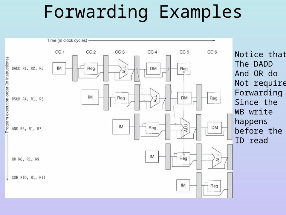
Forwarding Examples
Notice thatThe DADDAnd OR do Not requireForwardingSince theWB writehappensbefore the ID read
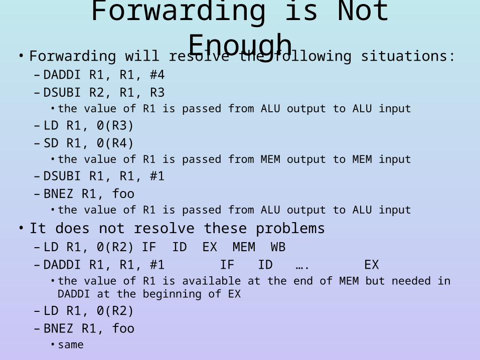
Forwarding is Not Enough• Forwarding will resolve the following situations:
– DADDI R1, R1, #4– DSUBI R2, R1, R3
• the value of R1 is passed from ALU output to ALU input
– LD R1, 0(R3)– SD R1, 0(R4)
• the value of R1 is passed from MEM output to MEM input
– DSUBI R1, R1, #1– BNEZ R1, foo
• the value of R1 is passed from ALU output to ALU input
• It does not resolve these problems– LD R1, 0(R2) IF ID EX MEM WB– DADDI R1, R1, #1 IF ID …. EX
• the value of R1 is available at the end of MEM but needed in DADDI at the beginning of EX
– LD R1, 0(R2)– BNEZ R1, foo
• same
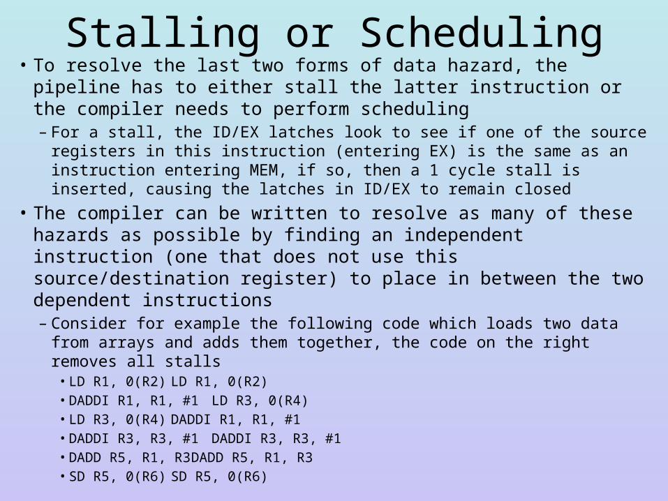
Stalling or Scheduling• To resolve the last two forms of data hazard, the pipeline has to either
stall the latter instruction or the compiler needs to perform scheduling– For a stall, the ID/EX latches look to see if one of the source registers in
this instruction (entering EX) is the same as an instruction entering MEM, if so, then a 1 cycle stall is inserted, causing the latches in ID/EX to remain closed
• The compiler can be written to resolve as many of these hazards as possible by finding an independent instruction (one that does not use this source/destination register) to place in between the two dependent instructions– Consider for example the following code which loads two data from arrays
and adds them together, the code on the right removes all stalls• LD R1, 0(R2) LD R1, 0(R2)• DADDI R1, R1, #1 LD R3, 0(R4)• LD R3, 0(R4) DADDI R1, R1, #1• DADDI R3, R3, #1 DADDI R3, R3, #1• DADD R5, R1, R3 DADD R5, R1, R3• SD R5, 0(R6) SD R5, 0(R6)
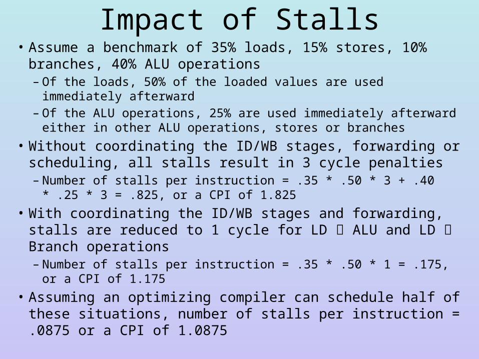
Impact of Stalls• Assume a benchmark of 35% loads, 15% stores, 10% branches,
40% ALU operations– Of the loads, 50% of the loaded values are used immediately afterward– Of the ALU operations, 25% are used immediately afterward either in
other ALU operations, stores or branches
• Without coordinating the ID/WB stages, forwarding or scheduling, all stalls result in 3 cycle penalties– Number of stalls per instruction = .35 * .50 * 3 + .40 * .25 * 3 = .825,
or a CPI of 1.825
• With coordinating the ID/WB stages and forwarding, stalls are reduced to 1 cycle for LD ALU and LD Branch operations– Number of stalls per instruction = .35 * .50 * 1 = .175, or a CPI of
1.175
• Assuming an optimizing compiler can schedule half of these situations, number of stalls per instruction = .0875 or a CPI of 1.0875
Branch Hazards• The last form of stall occurs with any branch that is taken
– Unconditional branches are always taken– Conditional branches are taken when the condition is true
• Why is the branch a problem? – Branch conditions (conditional branches) and branch target
locations (PC + offset) are both computed in the EX stage (we do not reset the PC until the MEM stage, but let’s move that MUX into the EX stage to further reduce the penalty by 1)• We have a 2 cycle penalty because we fetched two instructions in the
meantime (one is in IF, one is in ID)
– If the branch is taken, those 2 instructions need to be flushed from the pipeline, thus taken branches cause a penalty of 2 cycles
– There are several ways to handle the 2 cycle penalty, both through hardware and software
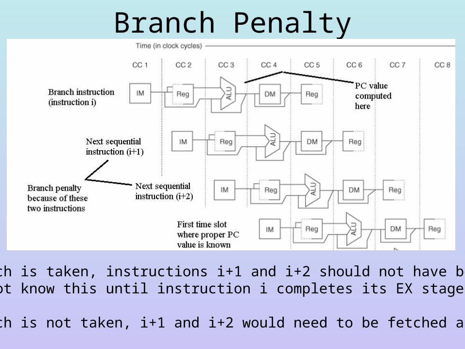
Branch Penalty
If the branch is taken, instructions i+1 and i+2 should not have been fetched, but we do not know this until instruction i completes its EX stage
If the branch is not taken, i+1 and i+2 would need to be fetched anyway,no penalty
MIPS Solutions to the Branch Penalty• Hardware solution– There is no particular reason why the PC + offset and
condition evaluation have to wait until the EX stage– Let’s add an ADDER to the ID stage to do PC + offset– We can also move the zero tester into the ID stage so that
the comparison takes place after registers are read• recall that the ID stage is one of the two shortest (time-wise) in
the pipeline, we should have enough time in this stage to read from registers and do the zero test
– If the branches are now being determined in the ID stage, it reduces the branch penalty to 1
• Software solution– The compiler can try to move a neutral instruction into
that penalty location, known as the branch delay slot
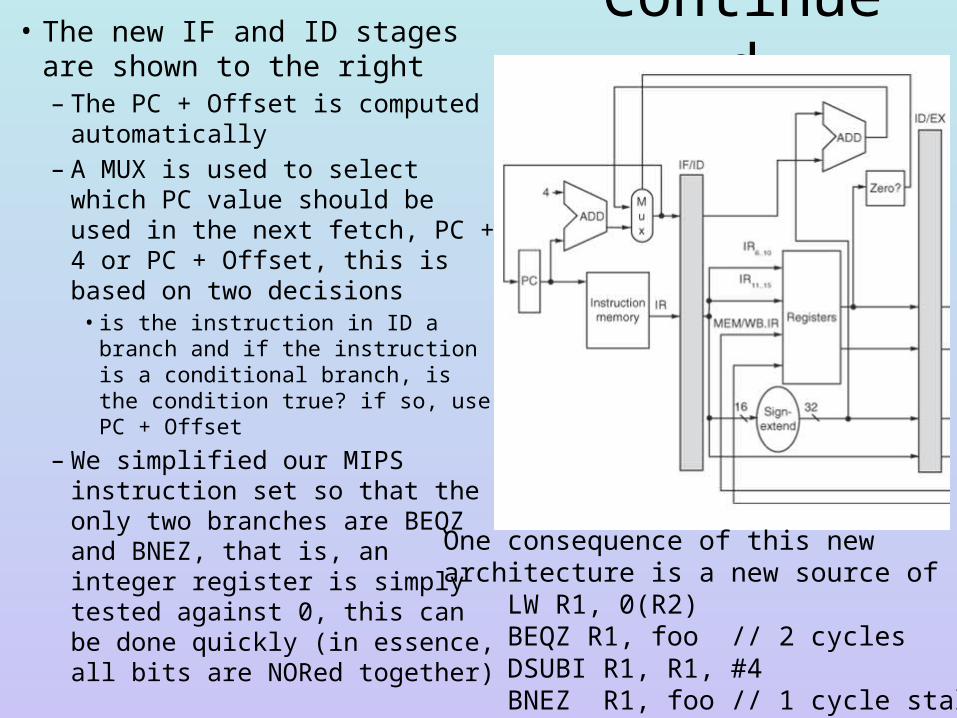
Continued• The new IF and ID stages are shown to the right– The PC + Offset is computed
automatically– A MUX is used to select which
PC value should be used in the next fetch, PC + 4 or PC + Offset, this is based on two decisions• is the instruction in ID a branch
and if the instruction is a conditional branch, is the condition true? if so, use PC + Offset
– We simplified our MIPS instruction set so that the only two branches are BEQZ and BNEZ, that is, an integer register is simply tested against 0, this can be done quickly (in essence, all bits are NORed together)
One consequence of this newarchitecture is a new source of stall LW R1, 0(R2) BEQZ R1, foo // 2 cycles DSUBI R1, R1, #4 BNEZ R1, foo // 1 cycle stall
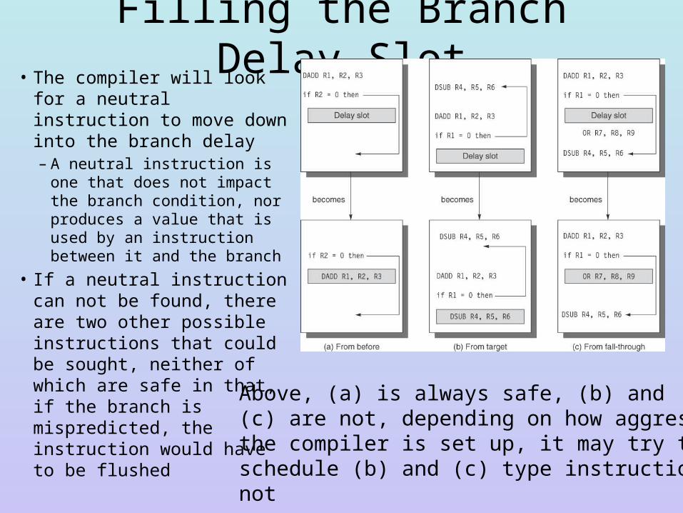
Filling the Branch Delay Slot• The compiler will look for a
neutral instruction to move down into the branch delay– A neutral instruction is one
that does not impact the branch condition, nor produces a value that is used by an instruction between it and the branch
• If a neutral instruction can not be found, there are two other possible instructions that could be sought, neither of which are safe in that, if the branch is mispredicted, the instruction would have to be flushed
Above, (a) is always safe, (b) and(c) are not, depending on how aggressivelythe compiler is set up, it may try to schedule (b) and (c) type instructions ornot
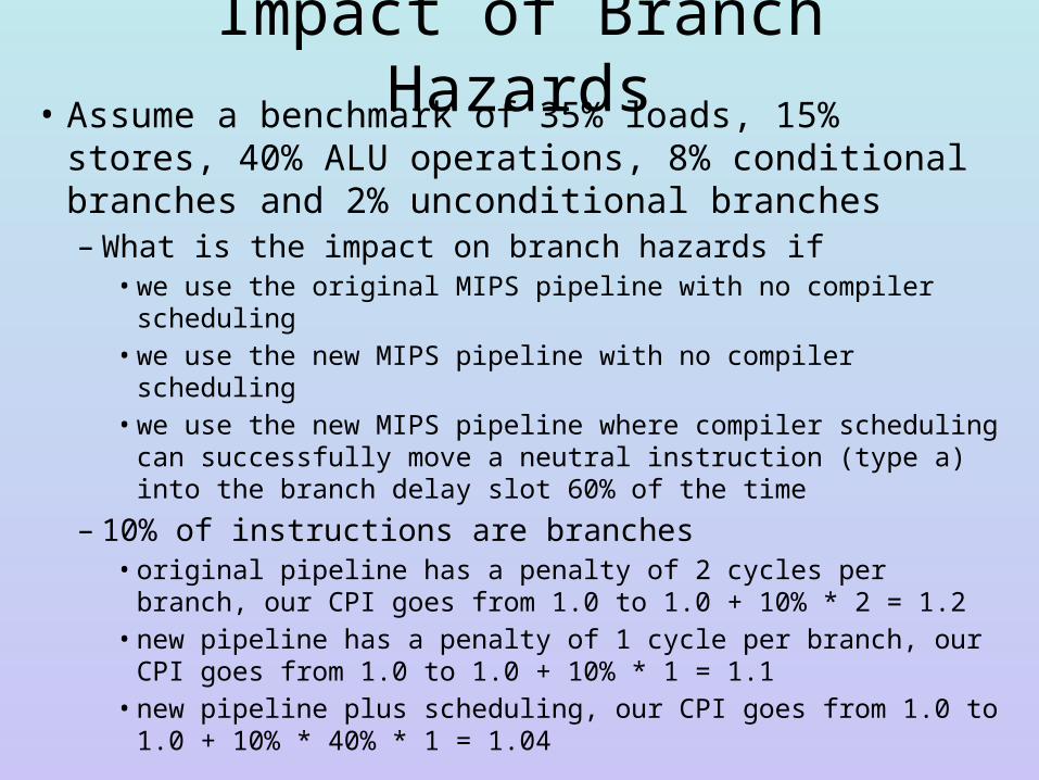
Impact of Branch Hazards• Assume a benchmark of 35% loads, 15% stores, 40%
ALU operations, 8% conditional branches and 2% unconditional branches– What is the impact on branch hazards if
• we use the original MIPS pipeline with no compiler scheduling• we use the new MIPS pipeline with no compiler scheduling• we use the new MIPS pipeline where compiler scheduling can
successfully move a neutral instruction (type a) into the branch delay slot 60% of the time
– 10% of instructions are branches• original pipeline has a penalty of 2 cycles per branch, our CPI goes
from 1.0 to 1.0 + 10% * 2 = 1.2• new pipeline has a penalty of 1 cycle per branch, our CPI goes from
1.0 to 1.0 + 10% * 1 = 1.1• new pipeline plus scheduling, our CPI goes from 1.0 to 1.0 + 10% *
40% * 1 = 1.04
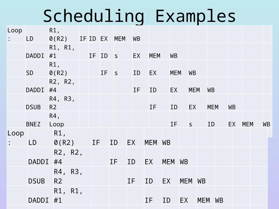
Scheduling Examples
• Stalls arise after the LD (data hazard), after the DSUB (data hazard caused by moving the branch computation to ID) and after the BEQZ (branch hazard)
• Below, the code has been scheduled by the compiler to remove all stalls with the SD filling the branch delay slot
Loop: LD R1, 0(R2) IF ID EX MEM WB DADDI R1, R1, #1 IF ID s EX MEM WB SD R1, 0(R2) IF s ID EX MEM WB DADDI R2, R2, #4 IF ID EX MEM WB DSUB R4, R3, R2 IF ID EX MEM WB BNEZ R4, Loop IF s ID EX MEM WBbranch delay (LD or next instruction sequential) s IF …
Loop: LD R1, 0(R2) IF ID EX MEM WB
DADDI R2, R2, #4 IF ID EX MEM WB
DSUB R4, R3, R2 IF ID EX MEM WB
DADDI R1, R1, #1 IF ID EX MEM WB
BNEZ R4, Loop IF ID EX MEM WB
SD R1, -4(R2) IF ID EX MEM WB
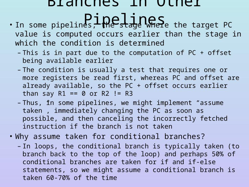
Branches in Other Pipelines• In some pipelines, the stage where the target PC value is
computed occurs earlier than the stage in which the condition is determined– This is in part due to the computation of PC + offset being available
earlier– The condition is usually a test that requires one or more registers be
read first, whereas PC and offset are already available, so the PC + offset occurs earlier than say R1 == 0 or R2 != R3
– Thus, in some pipelines, we might implement “assume taken”, immediately changing the PC as soon as possible, and then canceling the incorrectly fetched instruction if the branch is not taken
• Why assume taken for conditional branches?– In loops, the conditional branch is typically taken (to branch back to
the top of the loop) and perhaps 50% of conditional branches are taken for if and if-else statements, so we might assume a conditional branch is taken 60-70% of the time
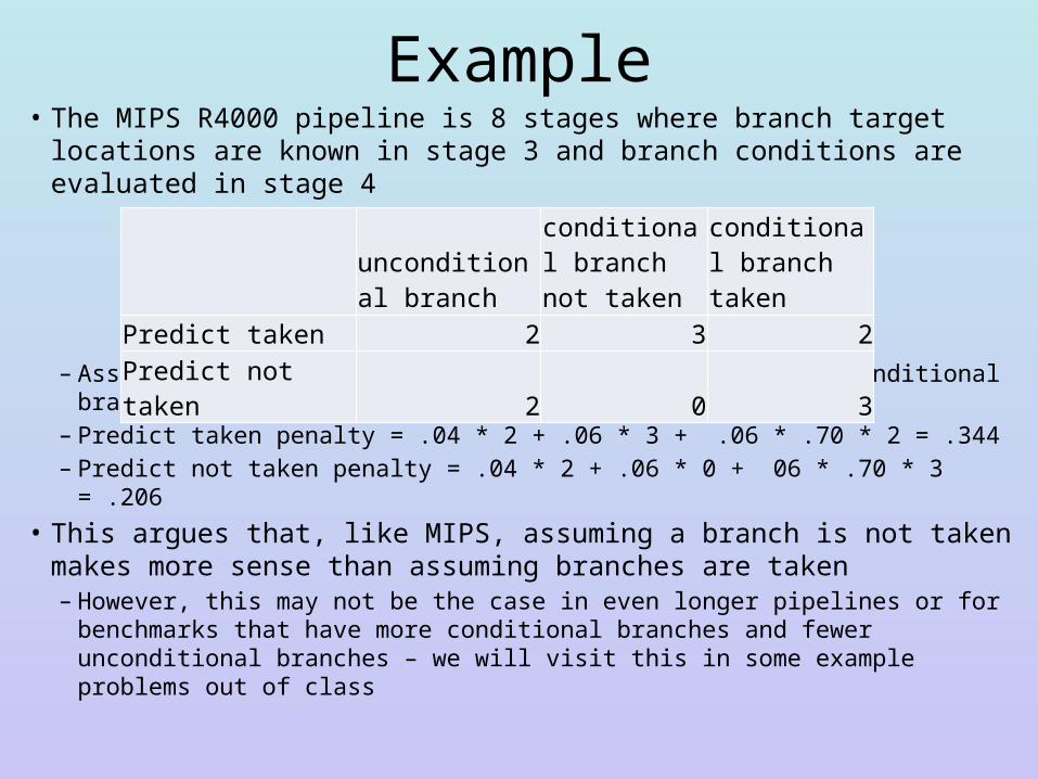
Example• The MIPS R4000 pipeline is 8 stages where branch target locations
are known in stage 3 and branch conditions are evaluated in stage 4
– Assume a benchmark with 4% unconditional branches, 6% conditional branches not taken and 70% conditional branches taken
– Predict taken penalty = .04 * 2 + .06 * 3 + .06 * .70 * 2 = .344– Predict not taken penalty = .04 * 2 + .06 * 0 + 06 * .70 * 3 = .206
• This argues that, like MIPS, assuming a branch is not taken makes more sense than assuming branches are taken– However, this may not be the case in even longer pipelines or for
benchmarks that have more conditional branches and fewer unconditional branches – we will visit this in some example problems out of class
unconditional branch
conditional branch not taken
conditional branch taken
Predict taken 2 3 2Predict not taken 2 0 3
Adding Floating Point to MIPS• FP operations take longer than integer
– Even a FP addition takes more time because we have to normalize both numbers (line up their decimal point) and then put them back into FP notation when done with the operation
– We could either lengthen the clock cycle time• this impacts all operations
– Or alter our EX stage to handle variable lengths– We choose the latter approach as it has less impact on the CPU’s
performance although it causes new problems with handling exceptions
• We will replace the current EX stage with a 4-device EX stage– The integer ALU– An FP adder– An FP multiplier (which will also be used for int multiplies)– An FP divider
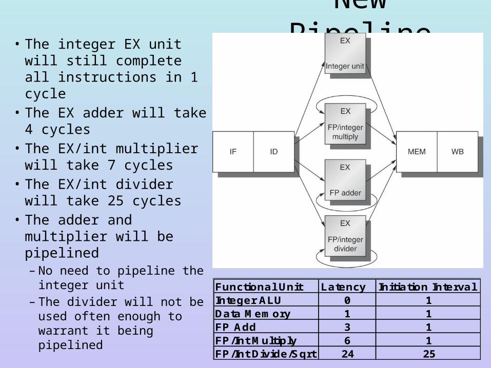
New Pipeline• The integer EX unit will
still complete all instructions in 1 cycle
• The EX adder will take 4 cycles
• The EX/int multiplier will take 7 cycles
• The EX/int divider will take 25 cycles
• The adder and multiplier will be pipelined– No need to pipeline the
integer unit– The divider will not be
used often enough to warrant it being pipelined
Functional Unit Latency Initiation IntervalInteger ALU 0 1Data Memory 1 1FP Add 3 1FP/Int Multiply 6 1FP/Int Divide/Sqrt 24 25
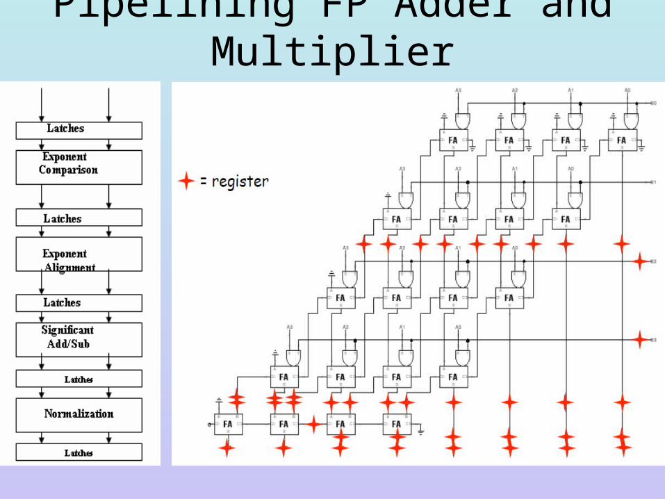
Pipelining FP Adder and Multiplier
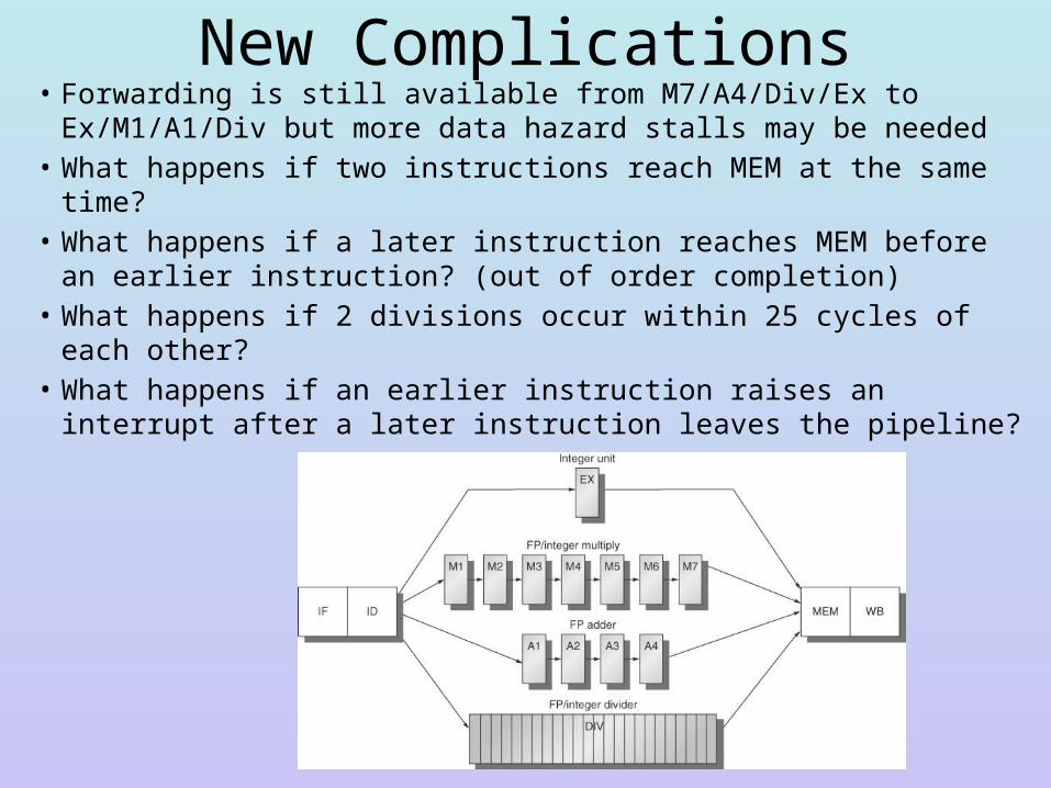
New Complications• Forwarding is still available from M7/A4/Div/Ex to
Ex/M1/A1/Div but more data hazard stalls may be needed• What happens if two instructions reach MEM at the same time? • What happens if a later instruction reaches MEM before an
earlier instruction? (out of order completion)• What happens if 2 divisions occur within 25 cycles of each other?• What happens if an earlier instruction raises an interrupt after a
later instruction leaves the pipeline?
The Need for Stalls
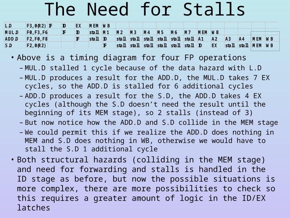
• Above is a timing diagram for four FP operations– MUL.D stalled 1 cycle because of the data hazard with L.D– MUL.D produces a result for the ADD.D, the MUL.D takes 7 EX cycles, so
the ADD.D is stalled for 6 additional cycles– ADD.D produces a result for the S.D, the ADD.D takes 4 EX cycles
(although the S.D doesn’t need the result until the beginning of its MEM stage), so 2 stalls (instead of 3)
– But now notice how the ADD.D and S.D collide in the MEM stage– We could permit this if we realize the ADD.D does nothing in MEM and
S.D does nothing in WB, otherwise we would have to stall the S.D 1 additional cycle
• Both structural hazards (colliding in the MEM stage) and need for forwarding and stalls is handled in the ID stage as before, but now the possible situations is more complex, there are more possibilities to check so this requires a greater amount of logic in the ID/EX latches
L.D F3, 0(R2) IF ID EX MEM WBMUL.D F0, F3, F6 IF ID stall M1 M2 M3 M4 M5 M6 M7 MEM WBADD.D F2, F0, F8 IF stall ID stall stall stall stall stall stall A1 A2 A3 A4 MEM WBS.D F2, 0(R2) IF stall stall stall stall stall stall ID EX stall stall MEM WB
Another Problem – WAW Hazards• We classify data hazards into three categories– RAW (read after write) – this is the type we have seen
earlier, an instruction needs to read from a register but the write takes place later, so we have to use forwarding and stalls to enforce the read after the write
– WAW (write after write) – the same register is written to by 2 instructions, but the order of the writes happen in the wrong order
– WAR (write after read) – this does not happen in MIPS and we will hold off on discussing it for now
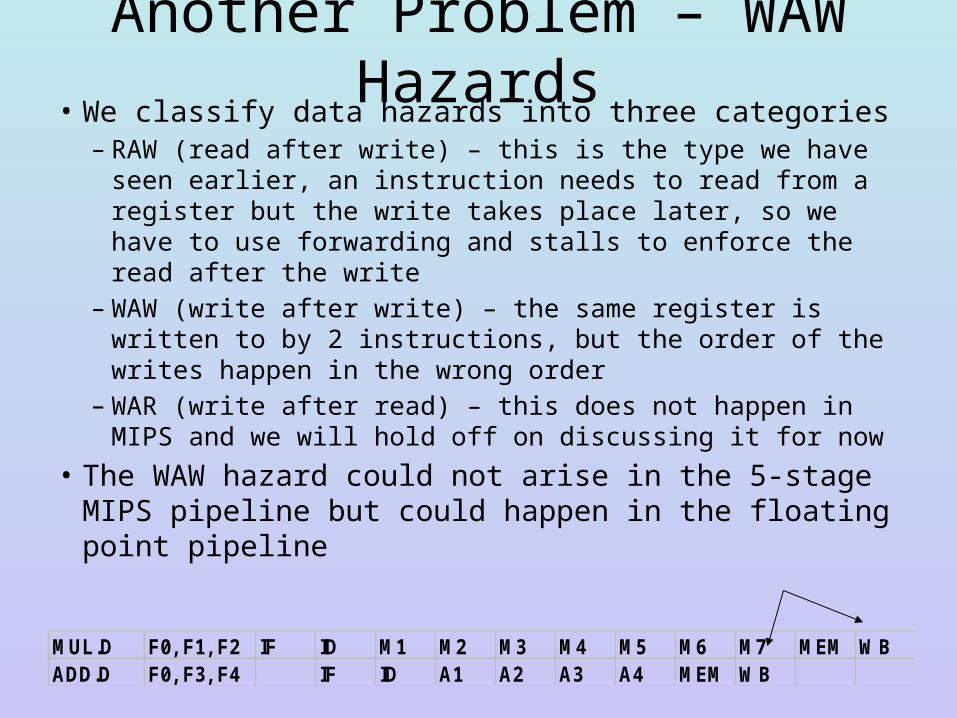
• The WAW hazard could not arise in the 5-stage MIPS pipeline but could happen in the floating point pipeline
MUL.D F0, F1, F2 IF ID M1 M2 M3 M4 M5 M6 M7 MEM WBADD.D F0, F3, F4 IF ID A1 A2 A3 A4 MEM WB
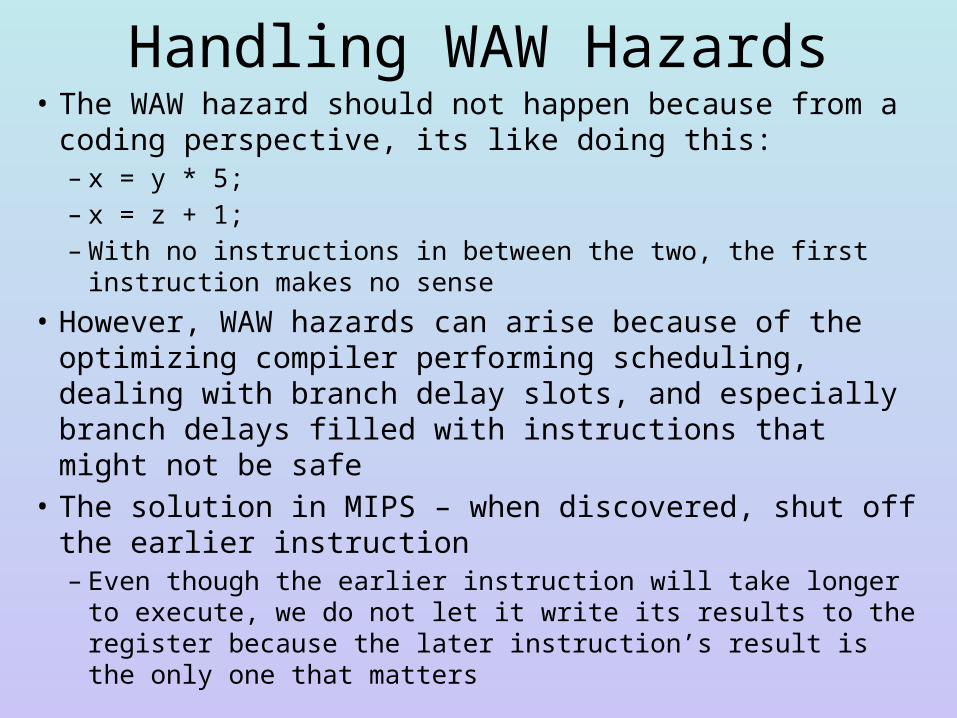
Handling WAW Hazards• The WAW hazard should not happen because from a coding
perspective, its like doing this:– x = y * 5;– x = z + 1;– With no instructions in between the two, the first instruction makes
no sense
• However, WAW hazards can arise because of the optimizing compiler performing scheduling, dealing with branch delay slots, and especially branch delays filled with instructions that might not be safe
• The solution in MIPS – when discovered, shut off the earlier instruction – Even though the earlier instruction will take longer to execute, we
do not let it write its results to the register because the later instruction’s result is the only one that matters
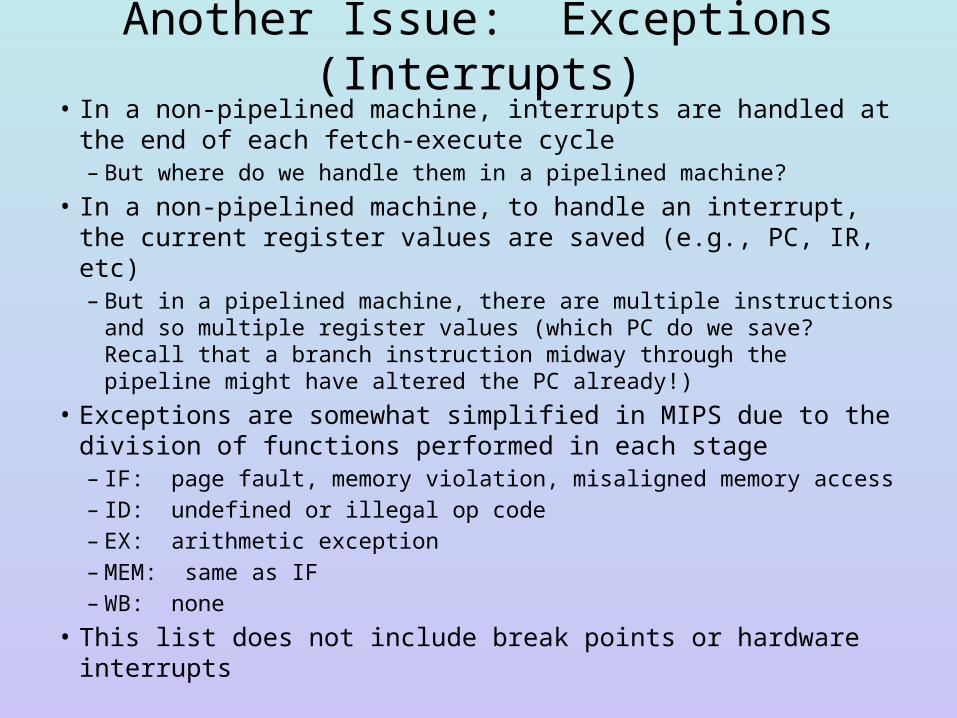
Another Issue: Exceptions (Interrupts)• In a non-pipelined machine, interrupts are handled at the end of
each fetch-execute cycle– But where do we handle them in a pipelined machine?
• In a non-pipelined machine, to handle an interrupt, the current register values are saved (e.g., PC, IR, etc)– But in a pipelined machine, there are multiple instructions and so
multiple register values (which PC do we save? Recall that a branch instruction midway through the pipeline might have altered the PC already!)
• Exceptions are somewhat simplified in MIPS due to the division of functions performed in each stage– IF: page fault, memory violation, misaligned memory access– ID: undefined or illegal op code– EX: arithmetic exception– MEM: same as IF– WB: none
• This list does not include break points or hardware interrupts
Simple Solution• At the stage an interrupt arises– Shut down all register writes and memory writes for
instructions from that point back to the beginning of the pipeline• Instructions further down the pipeline can complete (MEM and WB
stages)
– Insert a TRAP instruction in the next IF stage rather than an instruction fetch
– Save the PC of the faulting instruction when the TRAP is executed
• Problem: what if the faulting instruction is in the branch delay slot? In such a case, if the branch is taken, the PC value is already replaced with the branch target location– To resolve this problem, we can pass the old PC value down
the pipeline in the latches
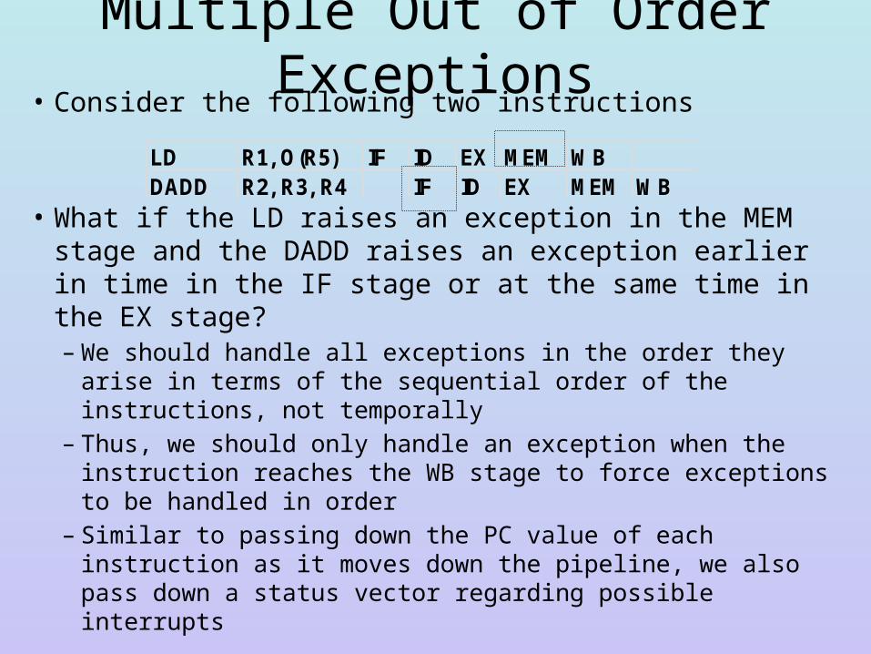
Multiple Out of Order Exceptions• Consider the following two instructions
• What if the LD raises an exception in the MEM stage and the DADD raises an exception earlier in time in the IF stage or at the same time in the EX stage?– We should handle all exceptions in the order they arise in terms
of the sequential order of the instructions, not temporally – Thus, we should only handle an exception when the instruction
reaches the WB stage to force exceptions to be handled in order– Similar to passing down the PC value of each instruction as it
moves down the pipeline, we also pass down a status vector regarding possible interrupts
LD R1, O(R5) IF ID EX MEM WBDADD R2, R3, R4 IF ID EX MEM WB
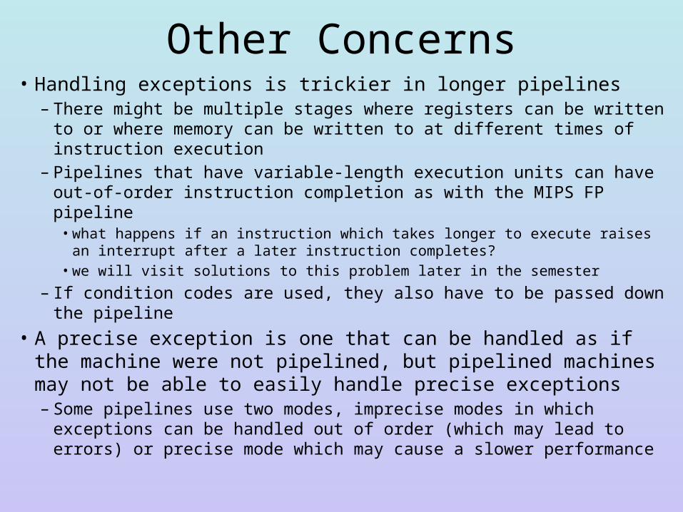
Other Concerns• Handling exceptions is trickier in longer pipelines
– There might be multiple stages where registers can be written to or where memory can be written to at different times of instruction execution
– Pipelines that have variable-length execution units can have out-of-order instruction completion as with the MIPS FP pipeline• what happens if an instruction which takes longer to execute raises an interrupt
after a later instruction completes? • we will visit solutions to this problem later in the semester
– If condition codes are used, they also have to be passed down the pipeline
• A precise exception is one that can be handled as if the machine were not pipelined, but pipelined machines may not be able to easily handle precise exceptions– Some pipelines use two modes, imprecise modes in which exceptions
can be handled out of order (which may lead to errors) or precise mode which may cause a slower performance


![Pipelining & Parallel Processing - ics.kaist.ac.krics.kaist.ac.kr/ee878_2018f/[EE878]3 Pipelining and Parallel Processing.pdf · Pipelining processing By using pipelining latches](https://img.pdfslide.net/doc/110x75/5d40e26d88c99391748d47fb/pipelining-parallel-processing-icskaistackricskaistackree8782018fee8783.jpg)