Embed Size (px)
Citation preview

1716
Korean J. Chem. Eng., 35(8), 1716-1725 (2018)DOI: 10.1007/s11814-018-0064-2
INVITED REVIEW PAPER
pISSN: 0256-1115eISSN: 1975-7220
INVITED REVIEW PAPER
†To whom correspondence should be addressed.E-mail: [email protected], [email protected] by The Korean Institute of Chemical Engineers.
Developing homogeneous ion exchange membranes derived from sulfonatedpolyethersulfone/N-phthaloyl-chitosan for improved hydrophilic
and controllable porosity
Zhixue Li*, Zhun Ma*,†, Yuting Xu*, Xiaomeng Wang*, Yongchao Sun*, Rong Wang*,Jian Wang**, Xueli Gao***,†, and Jun Gao*
*College of Chemical and Environmental Engineering, Shandong University of Science and Technology,Qingdao 266590, P. R. China
**The Institute of Seawater Desalination and Multipurpose Utilization, SOA, Tianjin 300192, P. R. China***Key Laboratory of Marine Chemistry Theory and Technology, Ministry of Education,
College of Chemistry and Chemical Engineering, Ocean University of China, Qingdao 266100, P. R. China(Received 28 November 2017 • accepted 10 April 2018)
AbstractIon exchange membranes (IEMs) composed of sulfonated poly (ether sulfone) (SPES) and N-phthaloyl chi-tosan (NPHCs) were synthesized. NPHCs was employed in membrane fabrication to improve the porosity and hydro-philicity of membranes. The effect of blend ratio of sulfonation (DS) and NPHCs content on physico-chemicalcharacteristics of home-made membranes was investigated. The morphology of prepared membranes was investigatedby Fourier transform infrared spectroscopy (FTIR), X-ray diffractometer (XRD) and scanning electron microscopy(SEM). SEM images revealed the formation of a more porous membrane structure and smoother surface. The electro-chemical and physical properties of CEMs were characterized comprising water content, contact angle, ion exchangecapacity (IEC) and thermal stability. Membrane water content, surface hydrophilicity and IEC were enhanced withincrease of DS and NPHCs blend ratios in casting solution. Furthermore, the diffusion coefficient was also improvedslightly with increase of DS and NPHCs blend ratios in prepared membranes. Membrane potential, permselectivity,transport number and areal membrane resistance all showed decreasing trends by the increase in NPHCs blend ratioin casting solution. These results indicated that the prepared membrane has good prospective and great potential fordesalination in electrodialysis applications.Keywords: Ion Exchange Membrane, Porous Structure, Homogeneous, Electrodialysis, Desalination
INTRODUCTION
Ion exchange membranes (IEMs) are widely studied and em-ployed as active separators in diverse electro-driven processes. Inthis kind of membrane, ion-functionalized groups attached to poly-mer backbone will dissociate after the permeation of sufficientwater molecules, releasing cations or anions for the transfer of cor-responding ions under the influence of an electrical potential dif-ference [1]. IEMs are efficient tools in industrial fields includingwater purification, food processing and many more processes [1-5].
Particularly, for desalination and ionic separation, IEMs shouldhave high ionic conductivity and permselectivity as well as goodthermal, chemical and mechanical stability, and high cost-effective-ness [6-13]. To achieve these properties, selection of preparationmethods, different polymeric matrix, variation of functional groupsand use of various additives are utilized as strategic tools. Amongthem, blend method for membrane modification is simple andeasy to operate, and this method is a technique to improve the elec-trical and physical properties of homopolymers [4-6]. Simultane-
ously, preparing porous ion exchange membranes may be a vitalstep in these applications [1,21,33].
High performance polymers with polyaryl skeletons such aspolyarylsulfone, polyphenylsulfide and poly(ether ether) ketone havebeen largely designed as alternative materials to IEMs [14-17].Among these high performance polymers, polyethersulfone (PES)has been regarded as a desirable polymer matrix candidate formembrane formation due to its good flexibility, mechanically sta-ble and low cost [7,18]. However, this polymer is a hydrophobicmaterial and consequently does not dissolve in conventional dipo-lar solvents, which restricts its application. To improve solubility indipolar solvents, PES was modified by various electrophilic substi-tutions. Among the PES derivatives, aryl substituted sulfonated PES(SPES) is a desired polymer which has been employed as a mem-brane material for gas separation, reverse osmosis, ultrafiltration, andcation exchange membranes. Mabrouk et al. studied the effect ofSPES on electrochemical applications [19], but these membraneshave a dense membrane structure that affects membrane proper-ties [21]. In recent years, polymer blending membranes have pro-duced significant results in electrodialysis. Amado et al. synthesizedpolystyrene/polyaniline composite membranes and obtained a bet-ter performance membrane with good zinc ion transport capacity[20]. In porous membrane research, Klaysom et al. exploited SPES

Developing homogeneous IEMs derived from SPES/HPHCs for improved hydrophilic and controllable porosity 1717
Korean J. Chem. Eng.(Vol. 35, No. 8)
as a membrane matrix to prepare the surface functionalized meso-porous silica porous ion exchange membrane, which enhancedionic conductivity of the membrane [21]. However, the prepara-tion process of these mesoporous silica membrane materials iscumbersome and sophisticated, so looking for a membrane mate-rial with simple preparation method is a problem to be solved inthis study.
Chitosan (CS), a cost-effective and eco-friendly polymer from theexoskeleton of crustaceans such as crabs and shrimps and fromthe cell walls of fungi, has been used as membrane material for thepreparation of ion exchange membrane due to its excellent bio-compatibility, biodegradability, non-toxicity, chemical and thermalstability [22-24]. CS is a cyclo-aliphatic polymer that contains cer-tain functional groups--amino groups (-NH2) and hydroxyl groups(-OH) that can provide CS with high hydrophilicity [25-28]. More-over, these functional groups allow chemical modification to im-prove the properties of chitosan membrane. However, since thereare no mobile hydroxyl ions in its structure, the pristine CS mem-brane shows much lower ionic conductivity, which limits the appli-cation of the material in various fields [24]. To improve the per-formance of chitosan membrane, chemical modification was em-ployed to modify the chitosan properties for preparing compositemembranes with better hydrophilicity, surface charge and biologi-cal compatibility by many researchers [29,30]. Nevertheless, thereare very limited works investigating the use of CS for membranedesign, especially porous IEMs suitable for various applications suchas electrodialysis, fuel cell, desalination and water purification [31-33].
The objective of this work was to prepare homogeneous ionexchange membranes with controllable porosities and structuresby blending SPES and NPHCs. The simplicity of the blending tech-nique allows the membrane to be cost-effective, provides the poten-tial for combining the attractive features of each blend componentwhile at the same time reducing their deficient characteristics. Theeffects of DS and NPHCs content on physicochemical, morpho-logical and ion exchange properties of the prepared membraneshave been evaluated. The structural composition, morphologies andthermal stability were characterized by Fourier transform infraredspectroscopy (FT-IR), X-ray diffractometer (XRD), scanning elec-tron microscopy (SEM), differential scanning calorimetry (DSC);and the basic membrane properties such as water content, contactangle, ion exchange capacity (IEC) and diffusion potential of NaClwere investigated by chemical and electrical methods. The resultsare valuable for further studies on the use of chitosan to improvethe dense structure of IEMs.
EXPERIMENTAL
1. MaterialsChitosan (80-95% degree of deacetylation) was purchased from
Sinopharm Chemical Reagent Company Ltd., China. Polyethersul-fone (PES, molecular weight is about 50000) flakes (ULTRASON®
E 6020 P, BASF) were dried 24 h at 80 oC in a vacuum before thereaction. Phthalic anhydride (99.7%) (Bodi, Tianjin), Dichloro-methane (Fuyu, Tianjin), N,N-dimethylformamide (DMF) (Bodi,Tianjin) and N-methylpyrrolidone (NMP) (Kermel, Tianjin) wereof analytical reagent. Chlorosulfonic acid and G4 sand filters were
provided by Qingdao Jingke Chemicals Co. (Shangdong, China).All other chemicals were of analytical reagent by Chengdu KeshiCo. (Chengdu, Sichuan).2. Sulfonated Polyethersulfone Preparation
Polyethersulfone (PES) was sulfonated according to the proce-dure reported in the literature [33]. The synthetic path is presentedin Scheme 1. Briefly, 4 g of PES was added to 50 g of dichlorometh-ane in a three-necked reaction flask under N2 atmosphere, anddissolved by stirring at room temperature to form homogeneoussolution. 5-10 mL of chlorosulfonic acid was transferred into aconstant pressure funnel, and then gradually and slowly added tothe solution at a period of time. After a determined stirred time,the mixture was precipitated into cold water under agitation, andthe products were recovered by filtration and washed with deion-ized water until pH was approximately 6-7. Finally, the sulfonatedpolyethersulfone (SPES) was dried under vacuum at 60 oC for twodays.
Degree of sulfonation (DS) is the fraction of the sulfonated mono-mer units after the reaction. It was determined as follows [34]. First,0.3 g of SPES was stirred in 30 ml of 2 M NaCl solution for 24 h torelease the H+ ions. Then the mixture was titrated with standard-ized 0.1 M NaOH solution using phenolphthalein as an indicator.The DS was calculated according to Eq. (1):
(1)
where MNaOH, VNaOH and W are the concentration of standardNaOH solution, volume of NaOH and weight of dry SPES, respec-tively. 244 g/mol is the molecular weight of PES repeat unit and 81is the molar mass of the SO3H group.3. N-phthaloyl Chitosan Preparation
N-phthaloyl chitosan (NPHCs) was prepared according to theprocedure reported in the literature [32,35]. The synthetic path ispresented in Scheme 2. In brief, 1 g chitosan was reacted with 4.48 gphthalic anhydride in 20ml DMF. The mixture was stirred at 130 oCfor 6 h, and then was poured into a large amount of ice-cold water
DS 0.244 MNaOH VNaOH
W 0.081 MNaOH VNaOH --------------------------------------------------------------- 100%
Scheme 1. Schematic representation of sulfonation of polyethersul-fone.

1718 Z. Li et al.
August, 2018
to give NPHCs. The product was purified by ethanol and ethylether; then was dried at 40 oC under vacuum for 24 h.4. Membrane Preparation
Several ratios of SPES and NPHCs were dissolved in NMP andstirred at 60 oC in a closed flask until a clear solution was obtained,then the stopper was removed and stirring continued for 10 h. Theviscous solution was filtered with G4 sand filter immediately andthen set for 24 hours. Membrane was prepared by casting viscoussolution on a glass plate and spread slowly to form a homogeneousliquid state, before being dried in an oven at 100 oC for 24 hoursand then under vacuum at 40 oC for 12 hours. The glass plate wasremoved and immersed in deionized water to separate the mem-brane from the glass plate. To discuss the effects of sulfonation degreeon the properties of composite membranes, different DS of SPESand NPHCs composite membranes were prepared in the samemanner.5. Polymers and Membrane Characterization5-1. Morphological and Structural Studies
Morphology of the membranes was observed using scanning elec-tron microscope (Hitachi S4800, Japan). Membrane surface wasplated with gold using a sputter coater. The potential was 10 kV andthe magnification of 50.0 k. To obtain sharp cross-sectional surfacefracture, the samples were cut in liquid nitrogen, then the capturedwater was dried in an oven at 40 oC overnight.
The functional groups of SPES, NPHCs and composite mem-branes were analyzed by using FT-IR Spectrometer (Nicolet 380,America). FT-IR scans were taken between 400 and 4,000 cm1 inabsorbance mode. The crystalline structure of samples was charac-terized by the X-ray diffractometer (Utima IV, Japan). XRD exper-iment was scanned between 5o and 50o at a rate of 8o/min.5-2. Water Content
Water content was determined by measuring the weight changebefore and after expansion in the distilled water [16]. The mem-
brane surface was washed with distilled water and then the mem-brane was dried in a vacuum desiccator for 48 hours, and the weightwas Wdry. The dried membrane was immersed in distilled waterfor 48 hours, and then the membrane was removed with absor-bent paper to dry the surface moisture, and the weight of Wwet wasrecorded. Water content was obtained from Eq. (2):
(2)
To reduce the experimental error, each sample was measuredthree times and their average value was recorded.5-3. Water Contact Angle Measurements
The contact angle of the membrane surface was measured bymeasurement apparatus (Krüss DSA100, Germany) according tothe fixed droplet method. Briefly, a water droplet (about 3L) on aflat dried membrane surface and the image was captured 5 secondsafter introducing the droplet. Deionized water was used as theprobe liquid in all measurements. At least five angles were meas-ured for each sample and then the average value was calculatedand used in this work. All experiments were carried out in theambient conditions.5-4. Thermal Stability of Membranes
The thermal properties of the blend membranes were exam-ined by the differential scanning calorimeter (Mettler Toledo DSC1, Switzerland) in nitrogen atmosphere. 10 mg samples were meas-ured in an Al crucible with a small hole. The samples were heatedfrom 30 oC to 300 oC at a heating rate of 10 oC·min1.5-5. Ion Exchange Capacity (IEC) and Fixed Ion Concentration(FIC)
Ion exchange capacity can reflect the concentration of activegroups within the membrane, but also reflect its ability to exchangewith the anti-ion level. IEC value was determined by titration [36].Briefly, the membrane was washed repeatedly with 1 M HCl andsoaked for 24 hours, and followed by washing with deionized waterto remove the H+ contained in the surface, immersing the mem-brane in 2 M NaCl for 48 hours. Then the solution was titratedwith NaOH using phenolphthalein as an indicator. The IEC valuewas obtained from Eq. (3):
(3)
where CNaOH (mol/L) is the concentration of NaOH, VNaOH (mL)refers to the volume of NaOH solution required for neutralization;Wdry is the weight of the dry membrane.
The fixed ion concentration (FIC) can be calculated by Eq. (4):
(4)
5-6. Diffusion CoefficientDiffusion coefficient reflects the ability of the electrolyte to pass
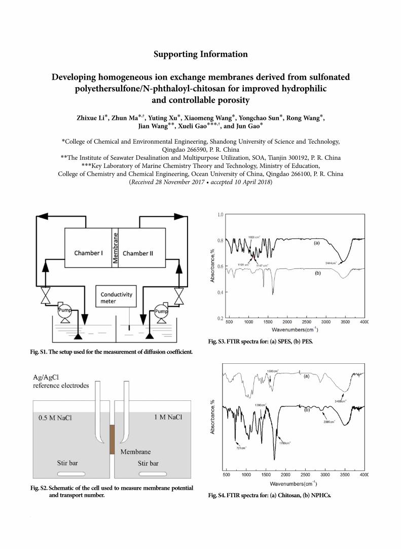
through the membrane under the effect of concentration, and hasa certain correlation with the membrane porosity. As shown inFig. S1, blend cation-exchange membranes were fixed in the mid-dle and contacted with circulating NaCl solution (chamber I) andcirculating deionized water (chamber II) on both sides. The con-ductivity of the deionized water was measured and recorded by a
Water content% Wwet Wdry
Wdry--------------------------- 100%
IEC CNaOH VNaOH
Wdry----------------------------------
FIC IEC
Water content----------------------------------
Scheme 2. Schematic representation of the prepared N-phthloyl chi-tosan.
Developing homogeneous IEMs derived from SPES/HPHCs for improved hydrophilic and controllable porosity 1719
Korean J. Chem. Eng.(Vol. 35, No. 8)
conductivity meter. Use the following formula (5) to calculate theresults [37,38].
(5)
where Ks is permeability coefficient of NaCl; D is diffusion con-stant of NaCl; tm is the thickness of membrane; v is volume ofNaCl solution; is slope of the linear relation between conductiv-ity and concentration at the deionized water side; K is the slope ofthe linear relation between time and conductivity at the deionizedwater side; s is the effective membrane area; C0 is concentrationdifference across the blend membrane.5-7. Membrane Electrochemical Properties 5-7-1. Membrane Resistance
The electrical resistance of the membranes was measured byusing a hand-made acrylic plastic cell composed of two parts sep-arated by a membrane, as described earlier [39,40]. The preparedmembrane was equilibrated in 0.5 M NaCl before being mountedin the cell between platinum electrodes with effective area of 1 cm2.The resistance of the membrane was measured at room tempera-ture by LCR meter operated at 10 KHz AC (TH2810D, Chang-zhou Tonghui Electronic Co., Ltd.). The membrane resistance iscalculated by using difference resistance between the cell (Rc) andelectrolyte solution (Rs) (Rm=RcRs).5-7-2. Membrane Potential and Transport Number
Membrane potential was measured in two compartment cells,in which a vertical membrane of 3.0 cm2 effective area separated twosolutions of 0.5 M NaCl and 1.0 M NaCl, respectively. The experi-mental setup is shown in Fig. S2. The potential difference acrossthe membrane was measured using a digital multimeter (Victor,model VC890D, China) which was connected to Ag/AgCl refer-ence electrodes. The measurement was repeated until a constantvalue was obtained. The transport number, ti
m, was then calcu-lated using the following modified Nernst equation [33]:
(6)
where tim is the transport number, Em is the measured potential
(V), R is the gas constant, T is the temperature (K), F is the Fara-day constant, n is the electrovalence of counter-ion and a1 and a2
are solutions electrolyte activities in contact membrane surfaces.The ionic permselectivity of membranes also is quantitatively ex-pressed based on the migration of counterion through the ion-exchange membrane as follows [41].
(7)
where t0 is the transport number of counter ions in the solutionphase.
RESULTS AND DISCUSSION
1. Membrane Structure--chemistryIR spectroscopy was used for the qualitative analysis; by identi-
fying specific absorption peaks for particular groups, the chemicalnature of materials such as chemical bonds can be evaluated. Hence
each substance was analyzed by using FT-IR to determine if theproduct had been synthesized successfully.
Fig. S3 shows the FT-IR spectrum of PES and SPES; the pres-ence of strong peak at 1,240 cm1 is assigned to the ether C-O-Cstretch of the PES moiety and the peak at 1,101cm1 due to O=S=Ostretching. Aromatic C-H bond could be detected at 1,068 cm1.After the sulfonation process, the bands at 1,026 cm1 and 1,147cm1 in the SPES spectrum could be assigned to the symmetricaland asymmetrical stretching vibrations of sulfonic groups, respec-tively [42,43]. Also, the increase in absorption peak at 3,444 cm1
was the result of stretching of the OH (-SO3H) groups [43].Fig. S4 presents the FT-IR spectrum of chitosan and NPHCs.
Absorption peak at 1,599 cm1 is related to -NH2 bending vibra-tion, and absorption at 2,885 cm1 is responsible for C-H bond.The broad peaks at 3,469 cm1 are substantially overlapping withchitosan, which is the combined band of O-H in the molecule andthe N-H vibrational peak in the amide. 1,780 cm1 is the charac-teristic peak of NPHCs. Absorption peak at 721 cm1 is the out-of-
Ks Dtm-----
vksC0------------
Em 2tim
1 RTnF------- a1
a2---- ln
Ps ti
m t0
1 t0-------------
Fig. 1. FT-IR spectra for different DS of SPES/NPHCs blend mem-branes (at SPES/NPHCs 90 : 10): (a) 15%DS, (b) 20%DS, (c)25%DS, (d) 30%DS.
Fig. 2. FT-IR spectra for different ratio of SPES/NPHCs blend mem-branes (at 30%DS): (a) 80 : 20, (b) 85 : 15, (c) 90 : 10, (d) 95 : 5.
1720 Z. Li et al.
August, 2018
intermolecular hydrogen bonds [45]. The decrease of peak valuein NPHCs implies the decrease of crystallinity, which is due to theacylation reaction promoting the destruction of hydrogen bond-ing involving -NH2 group. Simultaneously, the obtained NPHCsexhibited affinity for organic solvents consistent with previousresults, which makes the foundation for the blending of the twomaterials [46].
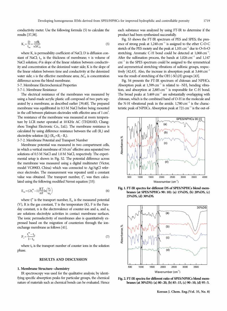
The X-ray diffractograms of the membranes prepared usingdifferent DS and SPES/NPHCs in various ratios are shown in Fig.3 and Fig. 4 respectively. From the XRD patterns of the membranes,the diffraction peaks were shifted at different degrees after the twomaterials were mixed (SPES shows broad bands at 2=20o, notshown in the literature [31]), indicating that there may exist inter-actions between SPES and NPHCs.
Fig. 3 shows the effect of DS on the crystallinity of the blendmembranes. With the increase of DS, the intensity of the crystal-line peak value at 2=17o decreased due to the hydrophilic group-SO3H. As presented in Fig. 4, NPHCs content in the blend mem-brane increases and the strength of the peak value at 2=22o de-creases, indicating that modified chitosan destroys the rigid struc-ture and makes the polymer transition from crystalline nature toamorphous nature. The crystalline portion of the membrane usu-ally prevents water from entering the membrane; thus the mostamorphous membrane is the most promising membrane in thedesalination process.2. Membrane Structure--thermal Stability
DSC is a commonly used thermal analysis tool that helps tofind the glass transition temperature (Tg) and analyzes the thermalstability of the material. Tg of the polymer is an important crite-rion for the compatibility of polymer components. The completelymiscible polymer blend has a single Tg, while the immiscible poly-mer blend has a plurality of Tg values [47,48].
The DSC curves of blend membranes with different DS and
plane bending vibration peak of O-substituted benzene in NPHCs,which confirms the presence of benzene rings and two imidegroups in the derivatives. Vibration of C-N bond at 1,390 cm1 wassignificantly enhanced, indicating that the reaction occurred mainlyon the amino group [44].
Fig. 1 and Fig. 2 represent the FT-IR of the different blendmembranes. Absorption peak at 1,780 cm1 indicates the presenceof NPHCs in the polymeric matrix. Absorption peak at 1,026 cm1
related to sulfonic groups confirms the presence of SPES in themembrane.
XRD patterns were used to determine the change of materialcrystalline nature. The crystalline nature plays a very important rolein understanding the substance’s solubility. Therefore, the XRDpatterns of each polymer were studied.
Fig. S5 represents the XRD pattern of NPHCs and chitosan. Chi-tosan shows broad bands at 2=20o due to intramolecular and
Fig. 3. X-ray diffractogram for different DS of SPES/NPHCs blendmembranes (at SPES/NPHCs 95 : 5): (a) 15%DS, (b) 20%DS,(c) 25%DS, (d) 30%DS.
Fig. 4. X-ray diffractogram for different ratio of SPES/NPHCs blendmembranes (at 30%DS): (a) 80 : 20, (b) 85 : 15, (c) 90 : 10, (d)95 : 5.
Fig. 5. DSC curves for different DS of SPES/NPHCs blend mem-branes (at SPES/NPHCs 95 : 5): (a) 15%DS, (b) 20%DS, (c)25%DS, (d) 30%DS.
Developing homogeneous IEMs derived from SPES/HPHCs for improved hydrophilic and controllable porosity 1721
Korean J. Chem. Eng.(Vol. 35, No. 8)
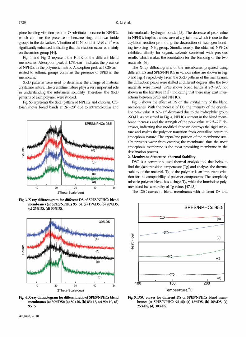
a single Tg value, indicating good miscibility between SPES andNPHCs due to the formation of van der Waals interactions. In Fig.6, with the increase of NPHCs content, the Tg of the blend mem-brane decreases, which means that the thermal stability of the mem-brane decreases with the increase of NPHCs content. The differencein Tg values is due to the polymer domain interactions producedby the different forms of various NPHCs content and also to thedifferences in the mechanical properties of the blend membranes.Moreover, SPES/NPHCs 80 : 20 have two Tg which may be attri-buted to the presence of ionic cluster [50].3. Membrane Structure-morphology
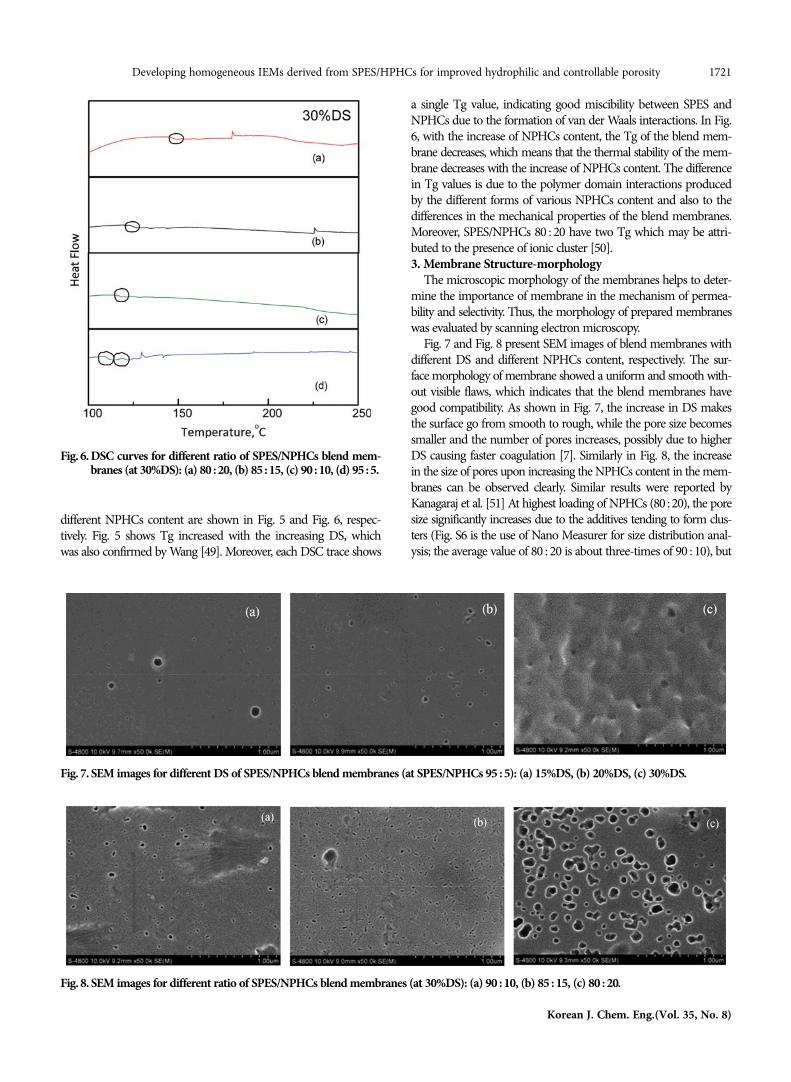
The microscopic morphology of the membranes helps to deter-mine the importance of membrane in the mechanism of permea-bility and selectivity. Thus, the morphology of prepared membraneswas evaluated by scanning electron microscopy.
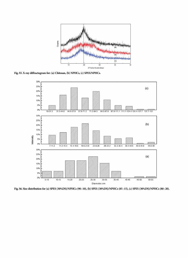
Fig. 7 and Fig. 8 present SEM images of blend membranes withdifferent DS and different NPHCs content, respectively. The sur-face morphology of membrane showed a uniform and smooth with-out visible flaws, which indicates that the blend membranes havegood compatibility. As shown in Fig. 7, the increase in DS makesthe surface go from smooth to rough, while the pore size becomessmaller and the number of pores increases, possibly due to higherDS causing faster coagulation [7]. Similarly in Fig. 8, the increasein the size of pores upon increasing the NPHCs content in the mem-branes can be observed clearly. Similar results were reported byKanagaraj et al. [51] At highest loading of NPHCs (80 : 20), the poresize significantly increases due to the additives tending to form clus-ters (Fig. S6 is the use of Nano Measurer for size distribution anal-ysis; the average value of 80 : 20 is about three-times of 90 : 10), but
different NPHCs content are shown in Fig. 5 and Fig. 6, respec-tively. Fig. 5 shows Tg increased with the increasing DS, whichwas also confirmed by Wang [49]. Moreover, each DSC trace shows
Fig. 6. DSC curves for different ratio of SPES/NPHCs blend mem-branes (at 30%DS): (a) 80 : 20, (b) 85 : 15, (c) 90 : 10, (d) 95 : 5.
Fig. 8. SEM images for different ratio of SPES/NPHCs blend membranes (at 30%DS): (a) 90 : 10, (b) 85 : 15, (c) 80 : 20.
Fig. 7. SEM images for different DS of SPES/NPHCs blend membranes (at SPES/NPHCs 95 : 5): (a) 15%DS, (b) 20%DS, (c) 30%DS.
1722 Z. Li et al.
August, 2018
the distribution of these is still relatively uniform. Under the prem-ise of ensuring the mechanical strength and thermal stability ofthe membrane, the porous ion exchange membrane has signifi-cant effect on the diffusion behavior and exhibits excellent perfor-mance in the electrodialysis process [21].4. Water Content and Ion-exchange Capacity (IEC)
A large number of hydrophilic functional groups in the ion ex-change membrane adsorb water molecules. Water molecules actas ion transport carriers, which directly affects the membrane sep-aration performance. Hence, it is important to select membraneswith the appropriate water content. Water content increases fromlower to higher sulfonation degree (from 15% to 30%, Table 1)due to more hydrophilic sulfonic acid groups in the membrane.NPHCs as a chitosan derivative contains polar functional groupslike hydroxyl, and ether groups can improve water content. In Table2, with the introduction of NPHCs, the water attracting capacityof membrane increases.
The data in the table indicate that water content is proportionalto the IEC. Likewise, NPHCs and sulfonation degree all affect themembrane ion exchange performance. Sulfonic acid groups andNPHCs provide active sites for proper interaction between ionsand the membrane surface, thereby enhancing the feasibility of ionexchange [52].5. Fixed Ion Concentration (FIC)
Membrane efficiency is affected by IEC and water content. HighIEC and water content can effectively reduce the membrane resis-tance, but also can cause excessive swelling of the membrane toreduce its ion selectivity and mechanical strength. So the mem-brane needs to have the appropriate IEC and water content. Oneimportant indicator of the synergistic effect of these two parame-ters is the membrane fixed ion concentration (FIC). Table 1 showsthe effect of DS on FIC of the prepared membranes. When the DSof SPES is 20%, the FIC value is 5.46 due to relatively high IEC andsuitable water content. Table 2 shows the effect of NPHCs contenton FIC of the prepared membranes. As the amount of NPHCsincreases, the FIC value decreases due to the swelling of the func-
tional groups [53]. FIC value increased first and then decreasedwith the increase of NPHCs content. At SPES : NPHCs 85 : 15, themembrane exhibited a suitable FIC compared to the others. Thehigh fixed ion concentration can have better control the pathwaysof counter ions traffic in the matrix of membrane and, therefore,increases the ionic selectivity.6. Membrane Potential, Transport Number and Permselectivity
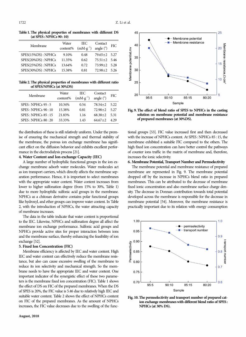
The membrane potential and membrane resistance of preparedmembrane are represented in Fig. 9. The membrane potentialdropped off by the increase in NPHCs blend ratio in preparedmembranes. This can be attributed to the decrease of membranefixed ionic concentration and also membrane surface charge den-sity. The decrease in Donnan contribution towards total potentialdeveloped across the membrane is responsible for the decrease inmembrane potential [54]. Moreover, the membrane resistance ispractically important due to its relation with energy consumption
Table 1. The physical properties of membranes with different DS(at SPES : NPHCs 90 : 10)
Membrane Watercontent%
IEC(mM·g1)
Contactangle (o) FIC
SPES(15%DS) : NPHCs 09.10% 0.48 79.65±2 5.27SPES(20%DS) : NPHCs 11.35% 0.62 75.51±2 5.46SPES(25%DS) : NPHCs 13.64% 0.72 73.99±2 5.28SPES(30%DS) : NPHCs 15.38% 0.81 72.98±2 5.26
Table 2. The physical properties of membranes with different ratioof SPES/NPHCs (at 30%DS)
Membrane Watercontent%
IEC(mM·g1)
Contactangle (o) FIC
SPES : NPHCs 95 : 50 10.34% 0.54 78.54±2 5.22SPES : NPHCs 90 : 10 15.38% 0.81 72.98±2 5.27SPES : NPHCs 85 : 15 21.83% 1.16 68.38±2 5.31SPES : NPHCs 80 : 20 33.33% 1.43 64.67±2 4.29
Fig. 9. The effect of blend ratio of SPES to NPHCs in the castingsolution on membrane potential and membrane resistanceof prepared membranes (at 30%DS).
Fig. 10. The permselectivity and transport number of prepared cat-ion exchange membranes with different blend ratio of SPES :NPHCs (at 30% DS).

Developing homogeneous IEMs derived from SPES/HPHCs for improved hydrophilic and controllable porosity 1723
Korean J. Chem. Eng.(Vol. 35, No. 8)
in the process. The membrane resistance declined with increasingof NPHCs blend ratio in casting solution (Fig. 9). This could beascribed to the increase in the ion exchange functional groups andan increase in the suitable ion conducting pathways throughoutthe membrane matrixes. This makes wide ionic transfer channelsin membrane matrix and improves the ions transportation, and soreduces the areal electrical resistance [39,40,54].
Both transport number and permselectivity of the prepared mem-branes are depicted in Fig. 10. It is evidenced that the transport num-ber and the permselectivity of the membrane tended to decreasewith increase of NPHCs blend ratio of the casting solution Thisresult can be explained with respect to the decrease in ionic con-centration, which facilitates the co-ion percolation through the mem-brane matrix and so reduces the selectivity and transport number.In addition, the increases of membrane water content and IECwith increase of NPHCs blend ratio in prepared membranes (dueto the NPHCs hydrophilic characteristic) makes wide ionic trans-fer pathways in membrane matrix and reduces the ionic sites domi-nation on ion traffic. This reduces the membrane selectivity andtransport number [41,54].7. Membrane Hydrophilicity
Contact angle is used to characterize the outermost changes inmembrane modification to evaluate the hydrophilicity of the mem-brane. The contact angle data of different DS and different NPHCscontent are reflected in Table 1 and Table 2, respectively. In Table 1the contact angle decreases as the DS increases, indicating theincrease in hydrophilicity of the blend membrane [55]. This canbe ascribed to the hydrophilic SO3H polar groups. NPHCs in theblend membrane can increase the hydrophilicity of the membraneobserved from Table 2. The value increases with the increase ofNPHCs content. The presence of polar carbonyl (OH) groups inNPHCs leads to membrane with higher surface hydrophilicity.Similar results were reported for polysulfone/N-phthaloyl chitosancomposite membranes by Padaki et al. [32].8. Membrane Porosity
As mentioned [21], porous ion exchange membranes have good
properties. The diffusion effect depends on the presence of activeion exchange groups and pores in the membrane. Therefore, toinvestigate the change in porosity of the prepared membranes underdifferent reaction conditions, the diffusion coefficient was meas-ured [56,57].
As seen in Fig. 11, the NaCl diffusion behavior increased withthe increase of DS, especially for M4, a large number of hydrophilicgroups (sulfonic acid groups) on the membrane surface contrib-ute to the transport of the electrolyte through the membrane. InFig. 12, the permeability coefficients of ion through the cation ex-change membrane with more NPHCs content were reported toincrease, which means that the porosity of the composite mem-branes increased by the effect of NPHCs. The increase in NPHCscontent makes the membrane porosity to accumulate more elec-trolyte ions and the diffusion of Na+ is strengthened, which is con-sistent with above-mentioned IEC experiments. As the NPHCscontent increases, the mechanical properties of the membrane arereduced, so the diffusion coefficient of the membrane 80 : 20 is notmeasured. The membrane M3 was facilitated when compared withthat of membrane in the literature [37], this study has gained moresatisfactory results.
CONCLUSIONS
Homogeneous ion exchange membranes by blending SPES andNPHCs with controllable porosity and improvement of hydrophilicwere successfully prepared. The characterization of membranes byFTIR, XRD and DSC reveals successful reaction and good com-patibility between SPES and NPHCs. The porous and smooth mor-phology of fabricated membranes was confirmed by SEM and dif-fusion coefficient. The electrochemical and physical properties ofblend membrane were affected by the sulfonation degree of theSPES and the content of NPCHs. Based on the results, the opti-mized blending ratio of membrane and sulfonation degree of theSPES should be 85 : 15 (SPES : NPHCs) and 30%, respectively. Inaddition, high DS and appropriate NPHCs content indeed improve
Fig. 11. The effect of DS on NaCl diffusion behavior of prepared ionexchange membranes (at SPES/NPHCs 95 : 5): M1, 15%DS;M2, 20%DS; M3, 25%DS; M4, 30%DS.
Fig. 12. The effect of NPHCs content on NaCl diffusion behavior ofprepared ion exchange membranes (at 30%DS): M1, SPES/NPHCs 95 : 5; M2, SPES/NPHCs 90 : 10; M3, SPES/NPHCs85 : 15.
1724 Z. Li et al.
August, 2018
hydrophilic and porosity of membrane. Membrane potential, perm-selectivity, transport number and membrane resistance all droppedoff with the increase of NPHCs blend ratio in home-made mem-brane. Although the molecular weight of chitosan, chitosan deacetyl-ation and many other factors will interfere with membrane per-formance, this work also provides some illumination for the prep-aration of porous ion-exchange membrane for the electrodialysisprocess.
ACKNOWLEDGEMENTS
Financial support by the Key Research Project of ShandongProvince (NO. 2017CXGC1004), Young Taishan Scholars Programof Shandong Province and Scientific Research Foundation for theReturned Overseas Chinese Scholars, State Education Ministry isgratefully acknowledged.
SUPPORTING INFORMATION
Additional information as noted in the text. This information isavailable via the Internet at http://www.springer.com/chemistry/journal/11814.
REFERENCES
1. J. Ran, L. Wu, Y. He, Z. Yang, Y. Wang, C. Jiang, L. Ge, E. Bakan-gura and T. Xu, J. Membr. Sci., 522, 267 (2017).
2. C. Vogel and J. Meier-Haack, Desalination, 342, 156 (2014).3. K. H. Choi and T. Y. Jeoung, Korean J. Chem. Eng., 19, 107 (2002).4. R.W. Baker, Membrane Technology and Applications, 2nd Ed. England,
Wiley (2004).5. S. Hosseini, A. Hamidi, A. Moghadassi, F. Parvizian and S. S.
Madaeni, Korean J. Chem. Eng., 32, 1827 (2015).6. J. Schauer and L. Brozova, J. Membr. Sci., 250, 151 (2005).7. M. Ghasemi, W. R. W. Daud, J. Alam, H. Ilbeygi, M. Sedighi, A. F.
Ismail, M. H. Yazdi and S. A. Aljlil, Energy, 96, 303 (2016).8. T. Chakrabarty, A. M. Rajesh, A. Jasti, A. K. Thakur, A. K. Singh, S.
Prakash, V. Kulshrestha and V. K. Shahi, Desalination, 282, 2 (2011).9. M. Zarrinkhameh, A. Zendehnam and S. M. Hosseini, Korean J.
Chem. Eng., 31, 1187 (2014).10. M. Reig, H. Farrokhzad, B. Van der Bruggen, O. Gibert and J. Luis
Cortina, Desalination, 375, 1 (2015).11. H. Farrokhzad, S. Darvishmanesh, G. Genduso, T. Van Gerven
and B. Van der Bruggen, Electrochim. Acta, 158, 64 (2015).12. F. Q. Mir and A. Shukla, Desalination, 372, 1 (2015).13. E. Y. Choi and S. H. Moon, Desalination, Korean J. Chem. Eng., 25,
1151 (2008).14. T. Chakrabarty, A. M. Rajesh, A. Jasti, A. K. Thakur, A. K. Singh, S.
Prakash, V. Kulshrestha and V. K. Shahi, Desalination, 282, 2 (2011).15. Y. Li, X. Zhang, G. He and F. Zhang, Int. J. Hydrogen Energy, 42,
2360 (2016).16. H. J. Cassady, E. C. Cimino, M. Kumar and M. A. Hickner, J.
Membr. Sci., 508, 146 (2016).17. L. Lei, X. Zhu, J. Xu, H. Qian, Z. Zou and H. Yang, J. Power Sources,
350, 41 (2017).18. A. Saleem, L. Frormann and A. Iqbal, Polym. Compos., 28, 785
(2007).19. W. Mabrouk, L. Ogier, S. Vidal, C. Sollogoub and J. F. Fauvarque, J.
Membr. Sci., 452, 263 (2014).20. F. D. R. Amado, E. Gondran, J. Z. Ferreira, M. A. S. Rodrigues and
C. A. Ferreira, J. Membr. Sci., 234, 139 (2004).21. C. Klaysom, R. Marschall, S. Moon, B. P. Ladewig, G. Q. M. Lu
and L. Wang, J. Mater. Chem., 21, 7401 (2011).22. J. Ma and Y. Sahai, Carbohydr. Polym., 92, 955 (2013).23. Y. Mansourpanah, A. Kakanejadifard, F. G. Dehrizi, M. Tabatabaei
and H. S. Afarani, Korean J. Chem. Eng., 32, 149 (2015).24. P. Srinophakun, A. Thanapimmetha, S. Plangsri, S. Vetchayakun-
chai and M. Saisriyoot, J. Clean Prod., 142, 1274 (2017).25. P. Mukoma, B. R. Jooste and H. C. M. Vosloo, J. Power Sources,
136, 16 (2004).26. R. Kumar, A. M. Isloor and A. F. Ismail, Desalination, 350, 102
(2014).27. S. S. Shenvi, S. A. Rashid, A. F. Ismail, M. A. Kassim and A. M.
Isloor, Desalination, 315, 135 (2013).28. H. S. Tsai and Y. Z. Wang, Polym. Bull., 60, 103 (2008).29. N. Yuana, R. Tsaia, M. Hob, D. Wanga, J. Laic and H. Hsieha,
Desalination, 234, 166 (2008).30. V. Tangpasuthadol, N. Pongchaisirikul and V. P. Hoven, Carbohydr.
Res., 338, 937 (2003).31. A. Muthumeenal, S. Neelakandan, P. Kanagaraj and A. Nagen-
dran, Renew. Energy, 86, 922 (2016).32. M. Padaki, A. M. Isloor and P. Wanichapichart, Desalination, 279,
409 (2011).33. C. Klaysom, S. Moon, B. P. Ladewig, G. Q. M. Lu and L. Wang, J.
Membr. Sci., 371, 37 (2011).34. C. Klaysom, B. P. Ladewig, G. Q. M. Lu and L. Wang, J. Membr.
Sci., 368, 48 (2011).35. R. Yoksan and S. Chirachanchai, Bioorg. Med. Chem., 16, 2687
(2008).36. M. Zhou, X. Chen, J. Pan, S. Yang, B. Han, L. Xue, J. Shen, C. Gao
and B. V. Bruggen, Desalination, 415, 29 (2017).37. H. L. Yeager and A. Steck, J. Electrochem. Soc., 128, 1880 (1981).38. M. Wang, Y. Jia, T. Yao and K. Wang, J. Membr. Sci., 442, 39 (2013).39. S. M. Hosseini, S. S. Madaeni and A. R. Khodabakhshi, Sep. Sci.
Technol., 46, 794 (2011).40. S. M. Hosseini, S. S. Madaeni, A. R. Heidari and A. Amirimehr,
Desalination, 284, 191 (2012).41. G. S. Gohil, V. V. Binsu and V. K. Shahi, J. Membr. Sci., 280, 210
(2006).42. W. Zhao, Q. Mou, X. Zhang, J. Shi, S. Sun and C. Zhao, Eur.
Polym. J., 49, 738 (2013).43. S. Sahebi, S. Phuntsho, Y. C. Woo, M. J. Park, L. D. Tijing, S. Hong
and H. K. Shon, Desalination, 389, 129 (2016).44. A. Zhu, T. Chen, L. Yuan, H. Wu and P. Lu, Carbohydr. Polym., 66,
274 (2006).45. R. J. Samuels, J. Polym. Sci., Part B: Polym. Phys., 19, 1081 (1981).46. K. Kurita, H. Ikeda, M. Shimojoh and M. Harata, Biomacromole-
cules, 3, 1 (2002).47. A. Behboudi, Y. Jafarzadeh and R. Yegani, J. Membr. Sci., 534, 18
(2017).48. Q. F. Alsalhy, Desalination, 294, 44 (2012).49. F. Wang, M. Hickner, Y. S. Kima, T. A. Zawodzinski and J. E.
Developing homogeneous IEMs derived from SPES/HPHCs for improved hydrophilic and controllable porosity 1725
Korean J. Chem. Eng.(Vol. 35, No. 8)
McGratha, J. Membr. Sci., 197, 231 (2002).50. E. B. Orler, D. J. Yontz and R. B. Moore, Macromolecules, 26, 5157
(1993).51. P. Kanagaraj, A. Nagendran, D. Rana, T. Matsuura, S. Neelakan-
dan, T. Karthikkumar and A. Muthumeenal, Appl. Surf. Sci., 329,165 (2015).
52. F. Heidary, A. R. Khodabakhshi and A. N. Kharat, Korean J. Chem.Eng., 33, 1380 (2016).
53. B. Tong, Md. M. Hossain, Z. Yang, C. Cheng, Y. Wang, C. Jiang
and T. Xu, J. Taiwan Inst. Chem. E., 67, 435 (2016).54. S. M. Hosseini, A. Gholami, S. S. Madaeni, A. R. Moghadassi and
A. R. Hamidi, Desalination, 306, 51 (2012).55. R. Guan, H. Zou, D. Lu, C. Gong and Y. Liu, Eur. Polym. J., 41,
1554 (2005).56. T. Sata, T. Funakoshi and K. Akai, Macromolecules, 29, 4029 (1996).57. T. Sata, Y. Ishii, K. Kawamura and K. Matsusaki, J. Electrochem.
Soc., 146, 585 (1999).
1726 Z. Li et al.
August, 2018
Supporting Information
Developing homogeneous ion exchange membranes derived from sulfonatedpolyethersulfone/N-phthaloyl-chitosan for improved hydrophilic
and controllable porosity
Zhixue Li*, Zhun Ma*,†, Yuting Xu*, Xiaomeng Wang*, Yongchao Sun*, Rong Wang*,Jian Wang**, Xueli Gao***,†, and Jun Gao*
*College of Chemical and Environmental Engineering, Shandong University of Science and Technology,Qingdao 266590, P. R. China
**The Institute of Seawater Desalination and Multipurpose Utilization, SOA, Tianjin 300192, P. R. China***Key Laboratory of Marine Chemistry Theory and Technology, Ministry of Education,
College of Chemistry and Chemical Engineering, Ocean University of China, Qingdao 266100, P. R. China(Received 28 November 2017 • accepted 10 April 2018)
Fig. S1. The setup used for the measurement of diffusion coefficient.
Fig. S2. Schematic of the cell used to measure membrane potentialand transport number.
Fig. S3. FTIR spectra for: (a) SPES, (b) PES.
Fig. S4. FTIR spectra for: (a) Chitosan, (b) NPHCs.
Developing homogeneous IEMs derived from SPES/HPHCs for improved hydrophilic and controllable porosity 1727
Korean J. Chem. Eng.(Vol. 35, No. 8)
Fig. S5. X-ray diffractogram for: (a) Chitosan, (b) NPHCs, (c) SPES/NPHCs.
Fig. S6. Size distribution for (a) SPES (30%DS)/NPHCs (90 : 10), (b) SPES (30%DS)/NPHCs (85 : 15), (c) SPES (30%DS)/NPHCs (80 : 20).

![pISSN: 0256-1115 DOI: 10.1007/s11814-014-0274-1 INVITED ... · cellulose, cow leather, wool fiber, NR, etc [4-8]. For example, graft-ing butyl acrylate onto cellulose enhances its](https://img.pdfslide.net/doc/110x75/5e1ea453d4a5ba6aa702865c/pissn-0256-1115-doi-101007s11814-014-0274-1-invited-cellulose-cow-leather.jpg)


![pISSN: 0256-1115 DOI: 10.1007/s11814-015-0179-7 ...346 J. Kim et al. January, 2016 cursor material for the backbone. In our previous works [11,12], the gold ion was directly mixed](https://img.pdfslide.net/doc/110x75/5f9a5e6683d5896bcf3a659d/pissn-0256-1115-doi-101007s11814-015-0179-7-346-j-kim-et-al-january-2016.jpg)