Embed Size (px)
Citation preview
Radian Corporation Report: MP-100 Line 28 February 92 Bruce F. Stacy, Consultant
INTRODUCTION The MP-100 system is an overhead conveyorized deep tank nickel/gold printed circuit plating system. Its main benefits are high production with less labor than conventional automatic or manual plating lines. The equipment was set up at Radian Corporation during November/December 1991. Nickel and gold plating processes were then installed by Engelhard and formulated to their specification (see Appendix I). Product plated on this equipment since start up, in December 1991, exhibited deposit pitting. PITTING ON VERTICAL VS. HORIZONTAL TABS It was discovered that only vertical tab configured product (product with finger tab rows perpendicular to the direction of travel in the MP-100) exhibited pitting when plated. Product with horizontal tab rows (product with finger tab rows parallel to the direction of travel) did not pit. Qualification and production of boards having only horizontal tab arrays commenced immediately after this discovery. The following test matrix was run to help isolate the cause of the pitting:1 1) 3521 circuit boards were turned 90 and then plated. Regardless of board design,
those tab arrays plated vertically pitted, those plated horizontally did not. 2) 3521's were plated at Radian, pits were present on the vertical tab arrays, but not
the horizontal arrays. This same product was also plated on Endicott's Deep Tank line and no pitting was present on any of the tab configurations.
3) 3521's were plated in the nickel and gold strike. They were then removed from
the line, turned 90, and plated with hard gold. Both vertical and horizontal tab configurations exhibited pitting.
4) 3521's were plated at four feet per minute. The current density in the nickel was
reduced from 156 ASF to 52 ASF and in the gold from 80 ASF to 27 ASF. The degree of pitting decreased noticeably, though gold and nickel thicknesses were below specification (a mean of 75u" Ni and 45u" Au).2
EQUIPMENT VARIABLES
Radian's MP-100 is unique in many respects. First, it was built as a "drop in" type cell. This means that solution flows over the sides of the cells as well as where the product for plating enters and exits. This leads to excessive aeration of the electrolyte,
1 Unless stated otherwise line speed = 4'/min., hard gold current density = 80 ASF, nickel current density = 156 ASF 2 This test was originally designed with only the gold current density decreased to better isolate the problem, these instructions
were not followed by production. Follow up tests were requested, where only one variable would be changed at a time, but the
decision was made to dump the nickel and gold chemistry before these could be carried out.
2
Radian Corporation Report: MP-100 Line 28 February 92 Bruce F. Stacy, Consultant
which causes higher electrical resistance across the cell, making current densities higher, causing deposit pitting. Microplate responded to this by installing solution deflectors in the nickel cell (this should be duplicated in the gold cell) which noticeably curbed aeration of the electrolyte. Second, the plating cells are twenty eight inches deep, while the other deep tank lines made by Microplate have cells only twenty four inches deep. It is presently unknown how this variable affects plating. Third, the nickel cell has higher agitation. There are three 5-HP pumps enabling solution pressures of 10psi, while Endicott has only two 5-HP pumps and utilizes solution pressures of 3-5psi. When the pumps at Radian were throttled back to 5psi, there was no difference in the degree of pitting. Fourth, sparger tubes run along each side of the tank, from top to bottom, and are perpendicular to the direction of board travel. Holes are 0.125" in diameter (they are 0.156" on Endicott's line) and spaced every two inches up the length of each sparger leg. In the front of the machine they are faced at the boards at a 45 angle in the direction of work flow. In the back of the machine they are pointed at the cathodes at a 45 angle into the direction the work comes from. These were pointed so the solution impinged directly on the boards to be plated (solution flow 90 to the direction of travel). Pitting was still present. CHEMICAL/PROCESS VARIABLES Initial plating bath formulations used on line were per Engelhard specification (see Appendix I) and varied from the specification established at IBM/Endicott. In February all plating baths were dumped and new ones formulated to Endicott specifications (see Appendix II). An oil like film identified to contain mainly silicon3 was found on the surface of both old and new baths, in line filters were downsized from ten to three micron to help eliminate this as a possible source of pitting. 1) Nickel Bath (cell length 8') The old nickel bath contained nickel bromide as an anode activator and NPA© Wetting Agent. The use of an anode activator did not appear to help anode corrosion. Periodic additions of wetting agent did not resolve the pitting problem. The old nickel bath utilized Inco S-Rounds© in the anode baskets, the new one Inco S-Pellets©, as recommended by IBM/Endicott. The S-Pellets© are small spheres varying in size from 0.125" to 0.500". The S-Rounds© are one inch diameter bottle cap shaped ingots. Theoretically the S-Pellets© provide greater surface area, better anode corrosion, and lower the voltage gradient across the nickel cell, decreasing the high current density effect seen by vertical tab rows. Observation is needed to determine the affect of S-pellets©. Cathode current densities used in the nickel at Radian were approximately 20 - 30
3
Silicon - a contaminant in plating baths. Causes deposit pitting and porosity problems. Method of removal - filtration.
3
Radian Corporation Report: MP-100 Line 28 February 92 Bruce F. Stacy, Consultant
% higher than those used in Endicott to plate the same nickel thickness (150 - 160u" mean) at four feet per minute. A 3521 plated in Endicott requires 35 amps/side (103 ASF) while at Radian requires 53 amps/side (156 ASF). 2) Gold Strike Bath (cell length 2') The old EAS© gold strike was a standard citrate gold bath. The new gold strike is the same citrate/oxalate formula used at IBM/Endicott. The oxalate should be maintained between 20 - 35 g/l. The presence of the oxalate gives this bath a greater degree of tolerance to metallic impurities, such as nickel. Cathode current densities were maintained at 10 ASF in both the new and the old strike bath. 3) Hard Gold Bath (cell length 4') The main difference in the old versus new hard gold bath formulations was the amount of cobalt added on make up. The old bath contained 1000 ppm of cobalt in solution, the new 700 ppm. The lower concentration of cobalt improves the cathode efficiency of the process, while still allowing the deposit to meet hardness and purity specifications. In the old hard gold bath, cathode current densities at Radian were 20% - 40% higher than those used at Endicott to plate the same gold thickness at four feet per minute. 4) New Plating Baths Made to IBM/Endicott Specification The old plating baths were dumped and new ones installed when: a) The cathode efficiency of the hard gold began to fall and nominal thicknesses could
not be met by increasing current density and reducing line speed. b) Pitting began to occur on horizontal tab arrays. c) Contamination was suspected of causing the low plating rate and contributing to
deposit pitting. The following test matrix was run after installation of the new baths: a) 3521's were run four feet per minute at 156 ASF in nickel, 10 ASF in gold strike,
and 80 ASF in the hard gold. A mean nickel thickness of 168u" was attained and gold thickness averaged 64u". The panel displayed gross pitting on vertical tab areas and slight pitting on horizontal tab areas.
b) The previous test was repeated using the same parameters, except the current
density in the hard gold was decreased to 60 ASF. Panels exhibited virtually no
4
Radian Corporation Report: MP-100 Line 28 February 92 Bruce F. Stacy, Consultant
pitting. It was remarked that these were the best 3521's seen off the line yet. Gold thickness averaged 54u".
c) The line speed was reduced to three feet per minute and 3521's were plated at 100
ASF in the nickel, 10 ASF in the gold strike, and 40 ASF in the hard gold. Average gold thickness was 60u" and average nickel thickness was 162u". There was virtually no pitting on vertical or horizontal tab arrays. A nitric acid vapor test was done according to IPC specifications on three sections of vertical tab areas. No pores were observed.
d) A Blue Bonnet─a board highly sensitive to pitting, because of its vertical tab
arrays─was plated under the same conditions as the previous test. Gold thickness ranged from 50 - 60u" and nickel thickness ranged from 95 - 135u" (lower than specification). Visual inspection at 30x revealed a marked decrease in the amount of pitting. When tab sections were subjected to nitric acid vapor testing, some pores less than 1 mil in diameter were found at 20x. This test was to be repeated to determine whether low nickel thickness caused the porosity.
CATHODE EFFICIENCY STUDIES Cathode efficiency testing was done in the lab on 1 liter samples of the old gold and nickel electrolytes (see Appendix III). Results showed the nickel chemistry to be performing at 100% cathode efficiency, these results were confirmed by Engelhard. The gold bath was 60% efficient at 40 ASF and 30% efficient at 75 ASF. Cathode efficiency in the actual plating cell was estimated for both nickel and gold (see Appendix IV) on both old and new bath chemistries. At 40 ASF the new gold was 20% more efficient than the old gold and at 80 ASF was 87% more efficient. From 100 to 156 ASF the new nickel bath is approximately 60% efficient, the old nickel from 75% to 60% over the same range. CONCLUSIONS Tests to verify which process, both nickel and gold or just one of them, was responsible for the pitting, though requested, were never run. Only one experiment came close (see New Plating Baths Made to IBM/Endicott Specification, page 4, experiments a & b), the current density on only the new hard gold bath was decreased 25% from the previous run and there was virtually no pitting on any tabs. Old bath formulations may have been capable of producing non-pitted deposits at lower line speeds and current densities, but requests to evaluate this were never met (see Pitting on Vertical Vs. Horizontal Tabs, page 1, test #4). Current densities exceeding chemical/equipment capabilities may have caused
5
Radian Corporation Report: MP-100 Line 28 February 92 Bruce F. Stacy, Consultant
premature decomposition of the plating baths, particularly the hard gold.4 The main cause of pitting in nickel/gold deposits is current density related. Vertical tab arrays are high current density areas. Pitting can be eliminated by: 1) Increasing the cathode efficiencies of the nickel and/or gold plating processes. 2) Increasing the hard gold efficiency and utilizing the nickel bath formulation and
operating parameters recommended by IBM/Endicott. 3) Reducing current densities and/or line speeds by 20 - 30% in both nickel and hard
gold plate. Cathode efficiency tests done off line are irrelevant to what is actually occurring in the MP-100 plating cells. A reliable method for testing cathode efficiency on line would be useful in controlling plating processes on this equipment. Development of a method is detailed in Appendix IV. Electrolytes formulated to IBM/Endicott specifications appear better suited to the MP-100 equipment than those recommended by Engelhard. There was a noticeable increase in the cathode efficiency of the new hard gold, closely matching the performance of the hard gold at IBM/Endicott. Use of S-Pellets© in the nickel bath appears to increase anode corrosion and may allow higher current densities, though more data is needed to confirm this. Maximizing cathode efficiency in the gold bath can be done by increasing gold content to 12 g/l. To achieve maximum efficiency in the nickel bath, redesign of process equipment may be necessary: i.e., an alteration in anode geometry/configuration, a further decrease in aeration, or redesign of the sparger system. There are equipment differences between Endicott and Radian that appear to give Radian a smaller operating window. This is particularly noticeable in the nickel plating cell. RECOMMENDATIONS 1) Increase cooperation between engineering and production departments so
problems on line can be solved in a scientific manner. This will save down time and allow collection of data that will prevent a repeat of past mistakes.
2) Dummy nickel bath every morning for 30 minutes at 100 amps with copper panels.
4 Decomposition was noticeable in the hard gold bath by the formation of a yellow precipitate (an insoluble gold/cyanide
compound), but could not be confirmed in the nickel bath due to the inability to get an ammonia analysis run.
6
Radian Corporation Report: MP-100 Line 28 February 92 Bruce F. Stacy, Consultant
This is to activate anodes. 3) Install solution deflectors in hard gold cell to retard solution aeration. 4) Increase gold content of E-75© hard gold bath to 12 g/l5. 5) Mask off exposed discontinuous copper on circuit boards to prevent copper
contamination of plating baths. 6) Increase operating range of oxalate in hard gold to 20 - 40 g/l from 25 - 35 g/l. 7) Maintain oxalate in gold strike bath at 20 - 35 g/l. 8) Analyze nickel bath for Fe, Cu, NH4, once per week and analyze gold baths for Ni,
Fe, Cu, once per week. 9) Execute cathode efficiency test on hard gold solution once a week, at 40 ASF and
80 ASF. This is a qualitative method of detecting a change in plating rate. 10) Run hull cell test of nickel bath twice per week at 5 amps for 5 minutes. 11) Carbon polish, using carbon filters, all plating baths once a week. Increase to
twice a week if plating rate of baths decline or when gold consumption is greater than 40 ounces or more per week.
12) Batch carbon treat nickel and gold baths every three months. When gold
consumption increases to over 40 ounces or more per week, batch treat every ninety days.
13) Install conveyor gutters to prevent debris from contaminating plating baths. 14) If a noticeable drop in plating rate occurs, determine why, don't just increase
operating current density. This reaction can shorten plating bath life and cause anode polarization.
15) When plating through holes, like Fast Track product, use lower current densities
and line speeds.
5 An increase in cobalt content of 50 - 200 ppm may also be necessary to maintain deposit brightness, hardness, and purity.
Radian Corporation Report: MP-100 Line 28 February 92 Bruce F. Stacy, Consultant
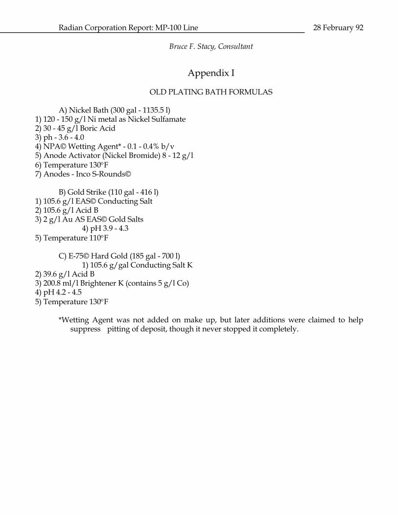
Appendix I OLD PLATING BATH FORMULAS A) Nickel Bath (300 gal - 1135.5 l)
1) 120 - 150 g/l Ni metal as Nickel Sulfamate 2) 30 - 45 g/l Boric Acid 3) ph - 3.6 - 4.0 4) NPA© Wetting Agent* - 0.1 - 0.4% b/v 5) Anode Activator (Nickel Bromide) 8 - 12 g/l 6) Temperature 130F 7) Anodes - Inco S-Rounds©
B) Gold Strike (110 gal - 416 l)
1) 105.6 g/l EAS© Conducting Salt 2) 105.6 g/l Acid B 3) 2 g/l Au AS EAS© Gold Salts
4) pH 3.9 - 4.3 5) Temperature 110F
C) E-75© Hard Gold (185 gal - 700 l) 1) 105.6 g/gal Conducting Salt K
2) 39.6 g/l Acid B 3) 200.8 ml/l Brightener K (contains 5 g/l Co) 4) pH 4.2 - 4.5 5) Temperature 130F
*Wetting Agent was not added on make up, but later additions were claimed to help
suppress pitting of deposit, though it never stopped it completely.
Radian Corporation Report: MP-100 Line 28 February 92 Bruce F. Stacy, Consultant
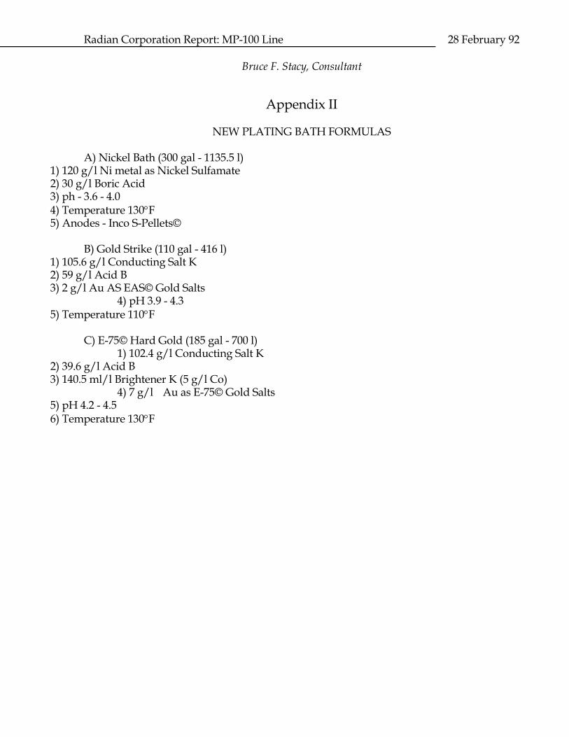
Appendix II NEW PLATING BATH FORMULAS A) Nickel Bath (300 gal - 1135.5 l)
1) 120 g/l Ni metal as Nickel Sulfamate 2) 30 g/l Boric Acid 3) ph - 3.6 - 4.0 4) Temperature 130F 5) Anodes - Inco S-Pellets©
B) Gold Strike (110 gal - 416 l)
1) 105.6 g/l Conducting Salt K 2) 59 g/l Acid B 3) 2 g/l Au AS EAS© Gold Salts
4) pH 3.9 - 4.3 5) Temperature 110F
C) E-75© Hard Gold (185 gal - 700 l) 1) 102.4 g/l Conducting Salt K
2) 39.6 g/l Acid B 3) 140.5 ml/l Brightener K (5 g/l Co)
4) 7 g/l Au as E-75© Gold Salts 5) pH 4.2 - 4.5 6) Temperature 130F
9
Radian Corporation Report: MP-100 Line 28 February 92 Bruce F. Stacy, Consultant
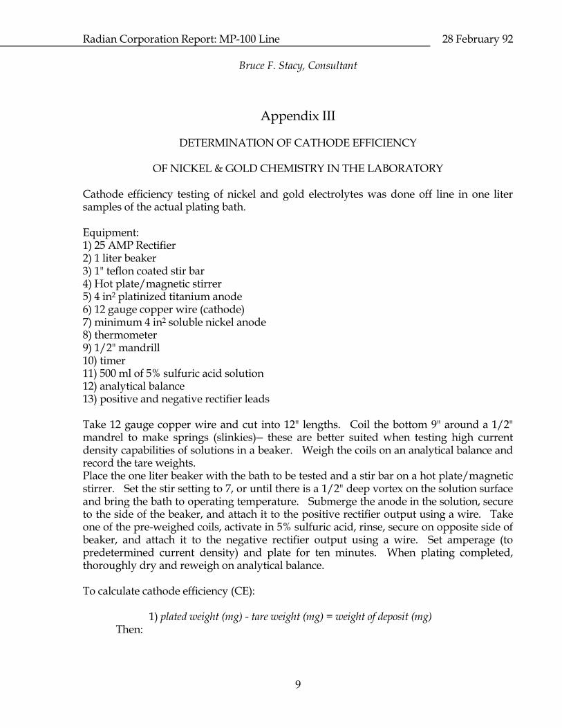
Appendix III DETERMINATION OF CATHODE EFFICIENCY OF NICKEL & GOLD CHEMISTRY IN THE LABORATORY Cathode efficiency testing of nickel and gold electrolytes was done off line in one liter samples of the actual plating bath. Equipment: 1) 25 AMP Rectifier 2) 1 liter beaker 3) 1" teflon coated stir bar 4) Hot plate/magnetic stirrer 5) 4 in2 platinized titanium anode 6) 12 gauge copper wire (cathode) 7) minimum 4 in2 soluble nickel anode 8) thermometer 9) 1/2" mandrill 10) timer 11) 500 ml of 5% sulfuric acid solution 12) analytical balance 13) positive and negative rectifier leads Take 12 gauge copper wire and cut into 12" lengths. Coil the bottom 9" around a 1/2" mandrel to make springs (slinkies)─ these are better suited when testing high current density capabilities of solutions in a beaker. Weigh the coils on an analytical balance and record the tare weights. Place the one liter beaker with the bath to be tested and a stir bar on a hot plate/magnetic stirrer. Set the stir setting to 7, or until there is a 1/2" deep vortex on the solution surface and bring the bath to operating temperature. Submerge the anode in the solution, secure to the side of the beaker, and attach it to the positive rectifier output using a wire. Take one of the pre-weighed coils, activate in 5% sulfuric acid, rinse, secure on opposite side of beaker, and attach it to the negative rectifier output using a wire. Set amperage (to predetermined current density) and plate for ten minutes. When plating completed, thoroughly dry and reweigh on analytical balance. To calculate cathode efficiency (CE): 1) plated weight (mg) - tare weight (mg) = weight of deposit (mg) Then:
10
Radian Corporation Report: MP-100 Line 28 February 92 Bruce F. Stacy, Consultant
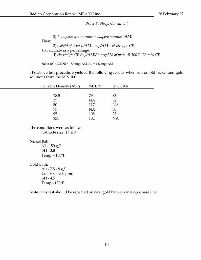
2) # amperes x # minutes = ampere minutes (AM) Then: 3) weight of deposit/AM = mg/AM = electrolyte CE To calculate as a percentage: 4) electrolyte CE (mg/AM)/ # mg/AM of metal @ 100% CE = % CE Note: 100% CE Ni = 18.3 mg/AM, Au = 122 mg/AM
The above test procedure yielded the following results when run on old nickel and gold solutions from the MP-100: Current Density (ASF) %CE Ni % CE Au 18.5 79 83 37 NA 52 50 117 NA 75 NA 30 95 108 23 151 102 NA The conditions were as follows: Cathode size: 1.5 in2 Nickel Bath: Ni - 150 g/l pH - 3.8 Temp. - 130F Gold Bath: Au - 7.5 - 8 g/l Co - 800 - 900 ppm pH - 4.5 Temp.- 130F Note: This test should be repeated on new gold bath to develop a base line.
11
Radian Corporation Report: MP-100 Line 28 February 92 Bruce F. Stacy, Consultant
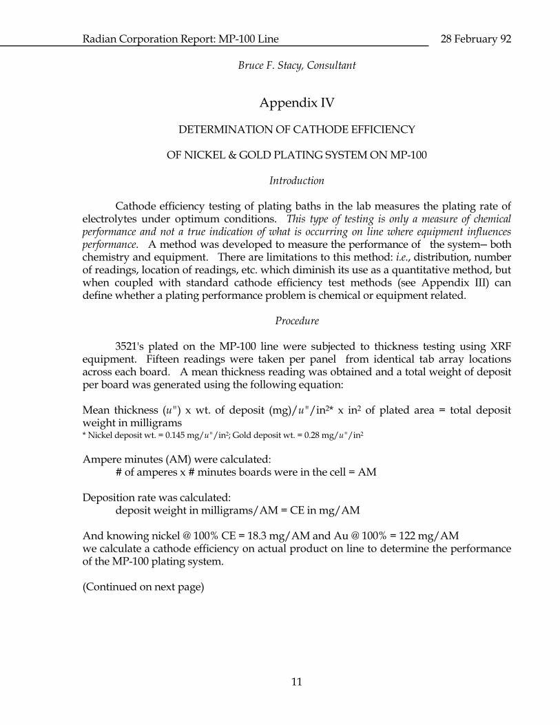
Appendix IV DETERMINATION OF CATHODE EFFICIENCY OF NICKEL & GOLD PLATING SYSTEM ON MP-100 Introduction Cathode efficiency testing of plating baths in the lab measures the plating rate of electrolytes under optimum conditions. This type of testing is only a measure of chemical performance and not a true indication of what is occurring on line where equipment influences performance. A method was developed to measure the performance of the system─ both chemistry and equipment. There are limitations to this method: i.e., distribution, number of readings, location of readings, etc. which diminish its use as a quantitative method, but when coupled with standard cathode efficiency test methods (see Appendix III) can define whether a plating performance problem is chemical or equipment related. Procedure 3521's plated on the MP-100 line were subjected to thickness testing using XRF equipment. Fifteen readings were taken per panel from identical tab array locations across each board. A mean thickness reading was obtained and a total weight of deposit per board was generated using the following equation: Mean thickness (u") x wt. of deposit (mg)/u"/in2* x in2 of plated area = total deposit weight in milligrams * Nickel deposit wt. = 0.145 mg/u"/in2; Gold deposit wt. = 0.28 mg/u"/in2 Ampere minutes (AM) were calculated: # of amperes x # minutes boards were in the cell = AM Deposition rate was calculated: deposit weight in milligrams/AM = CE in mg/AM And knowing nickel @ 100% CE = 18.3 mg/AM and Au @ 100% = 122 mg/AM we calculate a cathode efficiency on actual product on line to determine the performance of the MP-100 plating system. (Continued on next page)
12
Radian Corporation Report: MP-100 Line 28 February 92 Bruce F. Stacy, Consultant
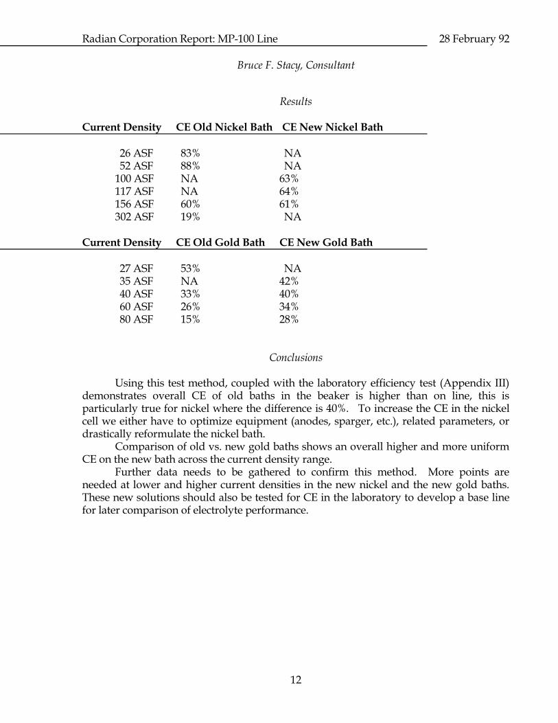
Results Current Density CE Old Nickel Bath CE New Nickel Bath 26 ASF 83% NA 52 ASF 88% NA 100 ASF NA 63% 117 ASF NA 64% 156 ASF 60% 61% 302 ASF 19% NA Current Density CE Old Gold Bath CE New Gold Bath 27 ASF 53% NA 35 ASF NA 42% 40 ASF 33% 40% 60 ASF 26% 34% 80 ASF 15% 28% Conclusions Using this test method, coupled with the laboratory efficiency test (Appendix III) demonstrates overall CE of old baths in the beaker is higher than on line, this is particularly true for nickel where the difference is 40%. To increase the CE in the nickel cell we either have to optimize equipment (anodes, sparger, etc.), related parameters, or drastically reformulate the nickel bath. Comparison of old vs. new gold baths shows an overall higher and more uniform CE on the new bath across the current density range. Further data needs to be gathered to confirm this method. More points are needed at lower and higher current densities in the new nickel and the new gold baths. These new solutions should also be tested for CE in the laboratory to develop a base line for later comparison of electrolyte performance.

13
Radian Corporation Report: MP-100 Line 28 February 92 Bruce F. Stacy, Consultant
Report for Radian Corporation:
RESOLUTION OF NICKEL/GOLD DEPOSIT PITTING ON MP-100 LINE 28 February 92
15
Radian Corporation Report: MP-100 Line 28 February 92 Bruce F. Stacy, Consultant


