Embed Size (px)
Citation preview
March 1991 Supersedes Price List 30-190, pages 1-16, dated March 15, 1990 Mailed to: E, D, C/30-100A
Hinge Assembly
• Ql '
Westinghouse Electric Corporation Distribution and Control Business Unit Standard Distribution Products Division Pitts burgh, Pennsylvania, U.S.A. 15220
Arc Chutes
Latch Kit
Renewal Parts Data 30-190
Page 1
Safety Switch Renewal Parts
• General Duty • Heavy Duty
Upper Base Assembly DOll
Spring and Lever Assembly
RHFN362
Terminals
Lower Fuse Block Assembly
. I I
www . El
ectric
alPar
tMan
uals
. com
Renewal Parts Data 30-190
Page 2
Heavy Duty Safety Switches Features
Instruction label for
Star mounting holes at top and bottom for easy ·mstallation
Unbreakable steel cross arm controls contacts; provides positive blade alignment
Easily-accessible fuse clips are reinforced
De-ion arc chute interrupts and cools arcs for longer switch life
Diamond pointed jaws prevent burning and pitting of current-carrying surfaces
Door latch securely holds door closed; permits padlocking in closed position
Door interlock prevents cover from being opened when switch is energized
Insulated shield prevents ---- accidental contact with
line terminals
in open or closed position
Front-operated handle th high-visibility
red vinyl sleeve
Ample knockouts n all four sides
and at rear of enclosure
for lower operating temperatures and long-life performance
Pressure-type aluminum line and load terminals can be used with copper or aluminum wire
Underwriters Laboratory Label
Line and load bases constructed of high-impact phenolic
DANGER: Hazard of electrical shock or burn. Be sure to TURN OFF POWER supply before working on equipment.
March 1991
www . El
ectric
alPar
tMan
uals
. com

March 1991
Rating Identification: Embossed nameplate enhances appearance and permanently identifies Westinghouse name, catalog numbers, volts ampere and horsepower ratings. No need to open door to obtain data.
Durable Finish: Entire enclosure is bonderized inside and out and coated with baked on enamel for maximum durability and resistance to rust. Scratches cannot spread even though they extend through to the bare metal.
Front Operated Handle: An integral part of switch mechanism, the easily accessible handle permanently controls contacts, permits close ganging, does not disconnect when door is opened. Red vinyl sleeve provides high visibility; indicates handle position (down for OFF; up for ON).
Padlocking: Operating handle can be padlocked in OFF position by three padlocks with %" hasps. Prevents closing of contacts- an essential requirement for heavyduty industrial applications. Handle can be padlocked in ON position by drilling hole in handle at position marked "X".
Removable Interior Parts: All interior parts are easily removable from the front if replacement is necessary.
Renewal Parts Data
30-190
Page 3
Heavy Duty Safety Switches Features
Dual Purpose Interlock: Prevents switch from being thrown ON with cover open; prevents cover from being opened unless switch is OFF. Authorized personnel can bypass both conditions by inserting screwdriver into interlock defeater (cover slot located above handle.)
Teaseproof Switch Mechanism: Over-center design with positive drive spring action maximizes strength of quick-make, quickbreak switch mechanism. Prevents contact teasing. Handle operates independently of cam and crossbar, allowing cover to be opened or closed in the unlikely event of drive spring breakage.
Steel Cross Arm and Yokes: Steel yokes in an impact-resistant glass polyester insulating block firmly engage steel crossarm that drives the moving blades and provides positive blade alignment.
Diamond-Pointed Break-Jaws: Moving contacts extend beyond the break-jaws, permitting the breaking arc to travel along the outside non current-carrying edges of jaws and blades. Prevents burning and pitting of current-carrying surfaces.
De-lon Arc Chute: Prevents arc damage by interrupting and cooling hot arcs. Molded material of chute is carbonizing and track resistant. Prolongs switch life; allows maximum horsepower ratings permitted by UL. www .
Elec
tricalP
artM
anua
ls . c
om
Renewal Parts Data 30-190
Page 4
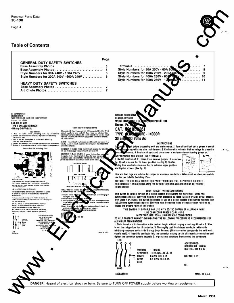
Table of Contents
Page GENERAL DUTY SAFETY SWITCHES Base Assembly Photos . . . . . . . . . . . . . . . . . . . . . . . . . . . . . . . 5 Base Assembly Photos . . . . . . . . . . . . . . . . . . . . . . . . . . . . . . . 5 Style Numbers for 30A 240V - 1 OOA 240V . . . . . . . . . . . . . . 6 Style Numbers for 200A 240V -600A 240V . . . . . . . . . . . . . 6
HEAVY DUTY SAFETY SWITCHES Base Assembly Photos . . . . . . . . . . . . . . . . . . . . . . . . . . . . . . . 7 Arc Chute Photos. . . . . . . . . . . . . . . . . . . . . . . . . . . . . . . . . . . . . 7
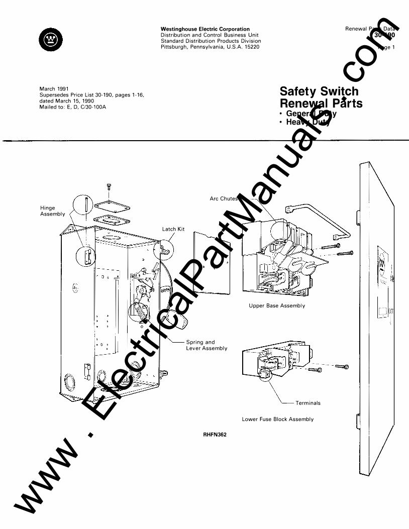
CIRCUIT PROTECTIVE DE VICES DIVISION WESTINGHOUSE ELECTRIC CORPORATION Beaver, Pa. 15009 CAT. NO. HFN265 TYPE 1 ENCLOSURE-INDOOR 400 Amp 240 Volts Ac
INSTRUCTIONS L Turn oil switch before proceeding with any maintenance. 2. Confirm with voltmeter that no voltage Is present before removing
or ins!�!ling fuses. 3. Turn oil and lock out all power to switch belm� proceedmg
with any other maintenance. 4.Conflrm wrth vollmeter that no voltage ls presant ln llneside terminals. 5. Replace all parts and close cover of enclosurebelore turning poweron.
Instructions for Installing Fuse
Loosenluae�lampbol1sa.u111clen11ytomoveclamp 1/4turnu shown lntenter pole plcture.Note: n11 nornecasurytoremovebolts
lnser11use and rtlurncllmpsloutremeposlllo n a sthownln lett pole plcturelhantlghtllllbolts.
lugs artsultableforcopptrconductors onfv
FOAFUSIBLE SWITC"ES.CONTINOUSLOAO CUAAEN T N O T T O EXCEEO
BOPERCENT OFTHE RATING OF FUSES EMPLOYEDIN OTHER THEN
MOTOR CIRCUITS
Forlusibl•swltcllaslha starting currant olmototlolmore than tlla
s�ndar d hornpower ratmgs may requl r a t h e u u o f lusuwlthappropriale
timadalaycharacterlstics
SUHABlfFOR UstAS SERVICE EGUIPMENTWHEN NEUTRALIS
PRD VIOED OR ORDERGROUNDING KIT GNK60FOIISEIIVICE
GROUND ANOGROUNDING ELECTROOE CDNNECTIONS
NOTFOR USEAS MOTOR CONTROLLEIIOVEII tOO HORSEPOWER
THISSWITCH IS SU!TABLE FOR USE WITH60/75COPPEIIWIRE
LINE
�' f' r , ... , .... h Groundable
l : ����� Used]
LOAD
5099A92H01
liNE CONNECTOR RANGES 2S0-750MCM CU ONLY
2 -300MCM3/0 •MAIN WIRE SIZE I!.TDROU£1Nf0
250750MCM-!iOOIN LBS
2-300MCM·3/0
NEUTRAL WIAE SIZEI!.TORQUEINFO H4750MCM CU AL
OR2250MCM1/0 3751NlBS
SHORT CIRCUIT WITHSTAND RATING
Whenused wllhCiass R fuusand wilh lield convarsion kiiCai.No.RFK·5 properly imlalled or when used with Class J fuses and with lower bsse assembly properly reposllioned.lhis switch ls sultablefor use on a clrcult capable of delivering not more than 100.000 RMS symmetrical ampera. 240 volts maximum.
DANGER· tlrtltUGiass R or J fuses are uslld.thls swllch may become afi1 t casualty ha,ard on circulls capable of dehverlng more than ID.OOORMS symmetrlcai amperes.
CONVERSION TO CLASS R FUSE S ·Install Class R rejection pins to the LINE side fuse holders as per inslruclions wllh convenion kit.
CONVERSION TO CLASS J FUSES · I. LDosen the lower base assambly by disengaging its two mounting bolls. 2. Move the lower base assembly towards the upper base assembtlesandresecurein lheset ol holesthatwlll provide the dlmension between luse holders shownbeiow:
A l501NC>< "" SWITCtl
IMPORTANT INFO. FOR ALUMINUM WIRE CONNECTIONS.
TO HE LP PROTECT AGAINST OVE RHE ATING THE FOLLOWING PROCE DURE IS RECOMMENDED FOR ALUMINUM TERMINATIONS
l.Strlp the wire ol ils insulation to the deslred length wilhout rlnglng or nicking the wire.
2. Wlre brushthe strlpped porlion ol conductor. 3. Thoroughly coat the slripped conductor wllh oxide inhibiting compound
such as theBurndyCorp.Penetrox(there are othar compounds thatwill work equally well).
4.1nsort the conductor into the connector making cerlain all strands are contained and lighten the cunnector screws securely.
5 Wipe excess compound from around the connectors.
ACCE SSORIES: GROUND KIT GNK-60 NE UTRAL Kll NK 400 or fiNK 400
INSTALUt; trf.
TEL
MADI: IN U.S.A
Terminals . . . . . . . . . . . . . . . . . . . . . . . . . . . . . . . . . . . . . . . . . . . . 7 Style Numbers for 30A 250V - GOA 600V . . . . . . . . . . . . . . . 8 Style Numbers for 100A 250V -200A 600V ............. 9 Style Numbers for 400A 250V -600A 600V . . . . . . . . . . . . . 10 Style Numbers for 800A 250V -1200A GOOV ............ 11
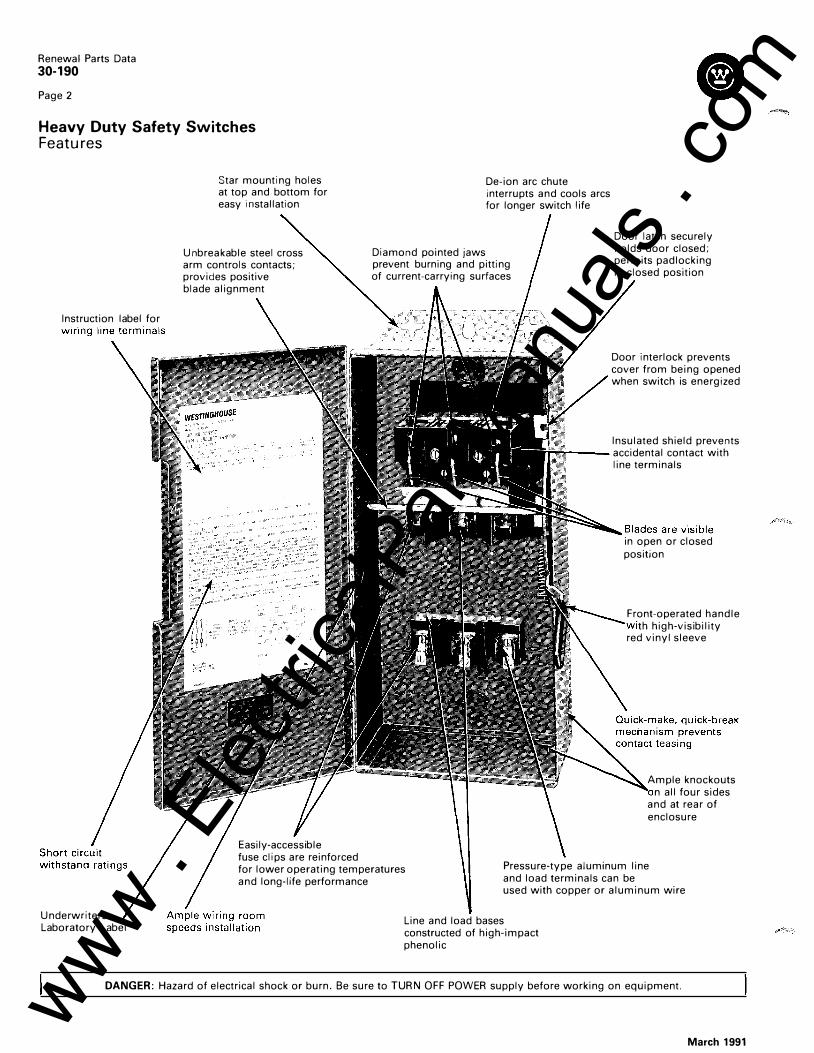
CIRCUIT PROTECTIVE DEVICES DIVISION WESTINGHOUSE ELECTRIC CORPORATION Beaver. Pa. 15009 CAT. NO. HUN361 TYPE 1 ENCLOSURE - INDOOR 30 amp 600 Volts Ac
INSTRUCTIONS 1. Turn off switch before proceeding with any maintenance. 2. Turn off and lock out al power to switch before proceeding with any other maintenance. 3. Confirm with voltmeter that no voltage Is present In line side lermlnals. 4. Replace all parts and close cover of enclosure bafore turning oowar on.
INSTRUCTIONS FOR WIRING LINE TERMINALS !"'"f.;�� l ::."•""':_---: l. Switch musl De off. 2. Loosen 2 arc screws lapprox. 5 lurns)(see I�• · -1 t··-.� .
.
tf ! fig. II and slide arc box to lower position lsaa fig. 2). 3 After ' _' · ,c, ., �-=C� wiring line lermlnala raturn arc box to exlreme upper position �{j' i ,,;:, _>·: - , and tighten screws. I See fig. 11. -=.;,.-;.::=_; o ' < � Line and load lugs are suitable lor copper or aluminum conductors. When uiaa as a two pol�·�wllch. use the two outside Switching Poles.
SUITABLE FOR USE AS A SERVICE EQUIPMENT WHEN NEUTRAL IS PROVIDED OR ORDER GROUNDING KIT GNK-6 130-60 AM PI FOR SERVICE GROUND ANO GROUNDING ELECTRODE CONNECTIONS.
SHORT CIRCUIT WITHSTAND RATING This switch Is suitable for use on a circuit capable of delivering nol more than 10.000 rms symmetrical amperas. 600 volls maximum when protacted by fuses !Class H or KJ or circuli breaker. Wllh Class R or J fuses. lhls switch Is sullable for use on a circuli capable of delivering nol more than I 00.000 rms symmetrical amperes. 600 volts max. Protective fuses or clrcll breaker rated not to exceed lhe ampere rating olthls swllch.
THIS SWITCH IS SUITABLE FOR USE WITH 60/75C COPPER OR ALUMINUM WIRE. LINE CONNECTOR RANGES CU-AL #14-2
IMPORTANT INFO. FOR ALUMIMUM WIRE CONNECTIONS. TO HELP PROTECT AGAINST OVERHEATING THE FOLLOWING PROCEDURE IS RECOMMENDED FOR ALUMINUM TERMINATIONS. 1. Slrlp lhe wire o! lis Insulation to lhe desired length wllhout ringing or nicking lilt! wire. 2. Wire brush the stripped portion of conductor. 3. Thoroughly coat the stripped conductor with oxide lnhlblllng compound such as the Burndy Corp. Penelrox !There are other compounds that will work equally wellj. 4. Insert tha conductor Into lhe connector making certain all strands are contained and tighten lhe connector screws securely. 5. wipe excess compound !rom around the connectors.
LINE
j{j� LOAD
509BA88H01
Insulated Groundable Neulral !when used)
'TORQUE 14-10 AWG. 35 LB. IN_ B AWG. 40 LB. IN. 6-4 AWG. 45 LB. IN.
ACCESSORIES: GROUND KIT GNK-6 NEUTRAL KIT IlK 60
INSTALLED BY:
TEL:
MADE IN U.S.A.
DANGER: Hazard of electrical shock or burn. Be sure to TURN OFF POWER supply before working on equipment.
March 1991 www . El
ectric
alPar
tMan
uals
. com
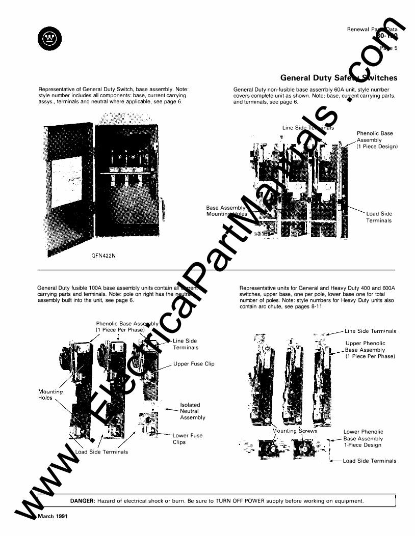
Representative of General Duty Switch, base assembly. Note: style number includes all components: base, current carrying assys., terminals and neutral where applicable, see page 6.
l
General Duty fusible 1 OOA base assembly units contain all current carrying parts and terminals. Note: pole on right has the neutral assembly built into the unit, see page 6.
Phenolic Base Assembly (1 Piece Per Phase)
Line Side Terminals
Renewal Parts Data 30-190
Page 5
General Duty Safety Switches
General Duty non-fusible base assembly 60A unit, style number covers complete unit as shown. Note: base, current carrying parts, and terminals, see page 6.
Base Assembly Mounting Holes
Line Side Terminals Phenolic Base Assembly (1 Piece Design)
Load Side Terminals
Representative units for General and Heavy Duty 400 and 600A switches, upper base, one per pole, lower base one for total number of poles. Note: style numbers for Heavy Duty units also contain arc chute, see pages 8-11.
Upper Phenolic Base Assembly (1 Piece Per Phase)
Upper Fuse Clip
March 1991
Load Side Terminals
Isolated -Neutral
Assembly
Lower Fuse Clips
Lower Phenolic - Base Assembly
i 1-Piece Design
r '+----Load Side Terminals
DANGER: Hazard of electrical shock or burn. Be sure to TURN OFF POWER supply before working on equipment. www . El
ectric
alPar
tMan
uals
. com

Renewal Parts Data 30-190
Page 6
General Duty Safety Switches --------,---�----,
1 Catalog Qty. Base Assy. Qty. Base Assy. Qty. Number : Req'd. Style No. Req'd. w/Neutral Req'd.
30A 240V
GFN221 RGFN221
GFN321N i RGFN321N,
GFN421N RGFN421N
I ��-�-�2
_:�_: _ -GOA 240V
GFN322N �� RGFN322N
GFN422N , RGFN422N RGUN222 , 1
GUN322 RGUN322
371D884G11 371D884G11
3710884G10 3710884G14 371 D884G14
3720150G10 3720150G12 3720150G12
I � j 1 '1
Style No.
3710884G13 3710884G13 371D884G15 I
I: L 6
3710884G15
�,
372D150G 11 6 3720150G11 6 372D150G13 6 3720150G13 6
6 6
-- �
Line & Load Terminals CD Style No.
750B437G06 7508437G06 750B437G06
627B213G03 627B213G03 627B213G03 627B213G03 627B213G03 627B213G03 627B213G03
tFor a complete description of catalog numbers see Safety Switch Catalog 30-150, Price List 30-125.
CD Each style number represents one terminal. Standard package quantity is (6) terminals.
,------::---
talog , Qty. Base Assy. Qty. Base Assy. Oty. mber , Req'd. Style No. Req'd. w/Neutral Req'd.
_ __ l _____ ____: ___ st_._y_le_
N_o
_. ____)__
100A 240V
GFN323N 1 RGFN323N 1
GFN423N 2 RGFN423N !2
GUN323 3 RGUN323 3
200A 240V
GFN324N 1 RGFN324N 1 1
GFN424N 2 RGFN424N 12
GUN324 3 RGUN324
505C044G06 505C044G06 505C044G06 505C044G06 , 1 505C044G07 ! 505C044G07
505C127G06 1 505C127G06 1 505C127G06 , 1 505C127G06 ' 1 505C127G07 505C127G07
505C044G05 1.
6:
6
505C044G05 505C044G05 505C044G05
16 6
505C127G05 6 505C127G05 6 505C127G05 6 505C127G05 ': 6
6 6
Line & Load Terminals CD Style No.
276A380G01 276A380G01 276A380G01 276A380G01 2760380G01 2760380G01
276A097G01 276A097G01 276A097G01 276A097G01 276A097G01 276A097G01
1 Catalog Number
Qty. Req'd.
Upper Base Assy. Style No.
Qty. Req'd.
Arc Chute Style No.
Qty. Req'd.
Lower Qty. Line & Load
i f---
400A 240V
IGFN325N@ 2
I RGFN325N@ 2 GFN325 3
! RGFN325 3 I GFN425N® 3 ' RGFN425NGJ 3
GUN325 3 RGUN325 3 ---�----
L600A 240V
I �FN326N�J
I RGFN326N®
GFN326 I RGFN326 GFN426N® RGFN426N®
GUN326 RGUN326
2 2 3 3 3 3 3 3
1229C81G15 1229C81G15 1229C81G15 1229C81G15 1229C81G15 1229C81G15 1229C81G16 1229C81G16
1229C82G15 1229C82G15 1229C82G15 1229C82G15 1229C82G15 1229C82G15 1229C82G16 1229C82G16
3
3 :3 3 3
-----------�--
4974022G02 4974022G02 4974D22G02 4974D22G02 4974022G02 4974D22G02 4974022G02 4974D22G02
4974022G02 4974022G02 4974022G02 4974022G02 4974D22G02 4974D22G02 4974D22G02 4974D22G02
tFor a complete description of catalog numbers see Safety Switch Catalog 30-150, Pnce List 30-125. CD Each style number represents one terminal. Standard package quantity is (6) terminals. 0 For Neutral order- 176C300G08 for NEMA 1 & NEMA 3R (After 1987) 0 For Neutral order- 176C300G09 for NEMA 3R (Prior to 1988) ® For Neutral order- 176C300G1 0 for NEMA 1 ® For Neutral order- 176C300G1 0 for NEMA 3R
Fuse Block Req'd. TerminalsCD
_______ S_t._ y _le _N_o_. __ ..L__�-----------S_ty._l _e _N _o _. _ __,
�---J 1229C83G05 1229C83G05 1229C83G06 1229C83G06 1229C83G06 1229C83G06
1229C83G07 1229C83G07 1229C83G08 1229C83G08 1229C83G08 1229C83G08
6 6 6 6 6 6 6 6
6 6 6
6 6 6
676B732G04 I 676B732G04 676B732G04 676B732G04 676B732G04 676B732G04 676B732G04 676B732G04
676B731G03 676B731G03 6768731G03 676B731G03 676B731G03 676B731G03 6768731G03 6768731G03
DANGER: Hazard of electrical shock or burn. Be sure to TURN OFF POWER supply before working on equipment.
March 1991 www . El
ectric
alPar
tMan
uals
. com
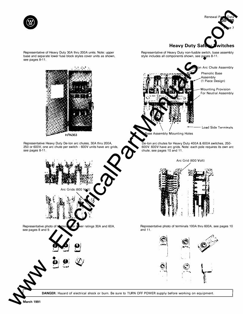
Representative of Heavy Duty 30A thru 200A units. Note: upper base and separate lower fuse block styles cover units as shown, see pages 8-11 .
Representative Heavy Duty De-ion arc chutes, 30A thru 200A, 250 or 600V, one arc chute per switch - 600V units have arc grids, see pages 8-11 .
Arc Grids (600 Volt)
Representative photo of terminals for lower ratings 30A and 60A, see pages 8 and 9.
Renewal Parts Data 30-190
Page 7
Heavy Duty Safety Switches
Representative of Heavy Duty non-fusible switch, base assembly style includes all components shown, see pages 8-11.
De-lon Arc Chute Assembly
Base Assembly Mounting Holes
Phenolic Base Assembly (1 Piece Design)
Mounting Provision For Neutral Assembly
De-ion arc chutes for Heavy Duty 400A & 600A switches, 250-600V. 600V have arc grids. Note: each pole requires its own arc chute, see pages 10 and 11.
Arc Grid (600 Volt)
Representative photo of terminals 1 OOA thru 600A, see pages 1 0 and 11.
�I -�
I
\r DANGER: Hazard of electrical shock or burn. Be sure to TURN OFF POWER supply before working on equipment.
March 1991 www . El
ectric
alPar
tMan
uals
. com
Renewal Parts Data 30-190
Page 8
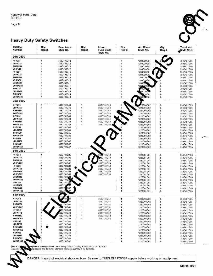
Heavy Duty Safety Switches
I Catalog ! Qty. Base Assy. Number
I Req'd. Style No.
30A 250V
HFN221 1 369D496G12 JHFN221 1 369D496G12 RHFN221 1 369D496G12 WHFN221 1 369D496G12 HFN321 1 369D496G15 JHFN321 1 369D496G15 RHFN321 1 369D496G15 I WHFN321 1 369D496G15 JHUN221 1 369D496G11
I WHUN221 1 369D496G11 HUN321 1 369D496G14 JHUN321 1 369D496G14 RHUN321 1 369D496G14 WHUN321 1 369D496G14
30A 600V
HFN261 1 368D741G46 JHFN261 1 368D741G46 RHFN261 1 368D741G46 WHFN261 1 368D741G46 HFN361 1 368D741G48 JHFN361 1 368D741G48 RHFN361 1 368D741G48 WHFN361 1 368D741G48 HUN261 1 368D741G45 JHUN261 1 368D741G45 RHUN261 1 368D741G45 WHUN261 1 368D741G45 HUN361 1 368D741G47 JHUN361 1 368D741G47 RHUN361 1 368D741G47 WHUN361 1 368D741G47
Qty. Req'd.
1 1 1 1 1 1 1 1
___ , ___ , ___ ------
I 60A
._25"-' 0'---V��
��
�������
�--��
HFN222 JHFN222 RHFN222 WHFN222 HFN322 JHFN322 RHFN322 WHFN322 JHUN222 WHUN222 HUN322 JHUN322 RHUN322
368D741G35
j WHUN322
�oo�v------�--� I JHFN262 , RHFN262
WHFN262 HFN362 JHFN362 RHFN362 WHFN362 HUN262 JHUN262 RHUN262 WHUN262 HUN362 JHUN362 RHUN362 WHUN362
368D741G35 368D741G35 368D741G35 368D741G38 368D741G38 368D741G38 368D741G38 368D741G34 368D741G34 368D741G37 368D741G37 368D741G37 368D741G37
368D741G41 368D741G41 368D741G41 368D741G41 368D741G43 368D741G43 368D741G43 368D741G43 368D741G40 368D741G40 368D741G40 368D741G40 368D741G42 368D741G42 368D741G42 368D741G42
Lower Fuse Block Style No.
368D741G53 368D741G53 368D741G53 368D741G53 368D741G54 368D741G54 368D741G54 368D741G54
368D741G49 368D741G49 368D741G49 368D741G49 368D741G50 368D741G50 368D741G50 368D741G50
368D741G51 368D741G51 368D741G51 368D741G51 368D741G52 368D741G52 368D741G52 368D741G52
tFor a complete description of catalog numbers see Safety Switch Catalog 30-150, Price List 30-125. CD Each style number represents one terminaL Standard package quanti1y is (6) terminals.
i Qty.
I Req'd.
I
1 1 1 1 1 1 1 1 1 1 1 1 1 1
1 1 1 1 1 1 1 1
I 1 I 1 1 1
! 1 I 1
1 1 1
I I I I L
Arc Chute I Qty. Style No. Req'd.
1289C20G01 I 6 1289C20G01 6 1289C20G01 6 1289C20G01 6 1289C20G01 6 1289C20G01 6 1289C20G01 6 1289C20G01 6 1289C20G01 6 1289C20G01 6 1289C20G01 6 1289C20G01 6 1289C20G01 6 1289C20G01 6
1220C94G02 6 1220C94G02 6 1220C94G02 6 1220C94G02 6 1220C94G02 6 1220C94G02 6 1220C94G02 6 1220C94G02 6 1220C94G02 6 1220C94G02 6 1220C94G02 6 1220C94G02 6 1220C94G02 6 1220C94G02 6 1220C94G02 6 1220C94G02 6
1220C81G01 6 1220C81G01 6 1220C81G01 6 1220C81G01 6 1220C81G01 6 1220C81G01 6 1220C81G01 6 1220C81G01 6 1220C81G01 6 1220C81G01 6 1220C81G01 6 1220C81G01 6 1220C81G01 6 1220C81G01 6
1220C94G02 6 1220C94G02 6 1220C94G02 6 1220C94G02 6 1220C94G02 6 1220C94G02 6 1220C94G02 6 1220C94G02 6 1220C94G02 6 1220C94G02 6 1220C94G02 6 1220C94G02 6 1220C94G02 6 1220C94G02 6 1220C94G02 6 1220C94G02 6
Terminals Style No. CD
750B437G06 750B437G06 750B437G06 750B437G06 750B437G06 750B437G06 750B437G06 750B437G06 750B437G06 750B437G06 750B437G06 750B437G06 750B437G06 750B437G06
750B437G05 I 750B437G05
750B437G05 750B437G05 750B437G05 750B437G05 750B437G05 750B437G05 750B437G05 750B437G05 750B437G05
I 750B437G05 I
750B437G05 I 750B437G05 750B437G05 750B437G05 :
-----�-·-
750B437G05 ·
-
j 750B437G05 750B437G05 750B437G05 750B437G05 750B437G05 750B437G05 750B437G05 750B437G05 750B437G05 750B437G05 750B437G05 750B437G05 750B437G05
750B437G05 750B437G05 750B437G05 750B437G05 750B437G05 750B437G05 750B437G05 750B437G05 750B437G05 750B437G05 750B437G05 750B437G05 750B437G05 750B437G05 750B437G05 750B437G05 --------�------------
DANGER: Hazard of electrical shock or burn. Be sure to TURN OFF POWER supply before working on equipment.
March 1991 www . El
ectric
alPar
tMan
uals
. com

Cl Renewal Parts Data
30-190
Page 9
Heavy Duty Safety Switches I ------�----------------- -- --------�-------- ----�-----,-----------,------------------, 1 Catalog Qty. Base Assy. J Qty. Lower Qty. Arc Chute �� Qty. Terminals 1 Number Req'd. Style No. 1 Req'd. Fuse Block Req'd. Style No. Req'd. Style No. CD
100A 250V
! Style No.
HFN223 1 3690679G23 I 1 3690679G32 JHFN223 1 3690679G23 I 1 3690679G32 RHFN223 1 3690679G23 1 3690679G32 WHFN223 1 3690679G23 1 3690679G32 HFN323 1 3690679G26 1 3690679G33 JHFN323 1 3690679G26 1 369D679G33 RHFN323 1 369D679G26 1 3690679G33 WHFN323 1 3690679G26 1 3690679G33 1
WHUN223 1 3690679G22 HUN323 1 3690679G25 JHUN323 1 3690679G25
6 6 6 6 6 6 6 6 6 6 6 6 6
JHUN223 1 369D679G22 11 I
RHUN323 II 1 3690679G25
WHUN323 1 3690679G25 �_________j____�- �-1 100A 600V
3690659G02 3690659G02 369D659G02 3690659G02 369D659G02 369D659G02 3690659G02 369D659G02 3690659G02 369D659G02 3690659G02 369D659G02 3690659G02 3690659G02 i 6
135A705G01 135A705G01 135A705G01 135A705G01 135A705G01 135A705G01 135A705G01 135A705G01 135A705G01 135A705G01 135A705G01 135A705G01 135A705G01 135A705G01 -------------
----,-------------,------ --------------------,------- --- ---------,---------------1 6 135A705G01
I
HFN263 JHFN263 RHFN263 WHFN263 HFN363 JHFN363 RHFN363 WHFN363 HUN263 JHUN263 RHUN263 WHUN263 HUN363 JHUN363 RHUN363 WHUN363
200A 250V
HFN224 JHFN224 RHFN224 WHFN224 HFN324 JHFN324 RHFN324 WHFN324 JHUN224 WHUN224 HUN324 JHUN324 RHUN324 WHUN324
200A 600V
HFN264 JHFN264 RHFN264 WHFN264 HFN364 JHFN364 RHFN364 WHFN364 HUN264 JHUN264 RHUN264 WHUN264 HUN364 JHUN364 RHUN364 WHUN364
3690679G29 369D679G29 3690679G29 3690679G29 369D679G31 3690679G31 369D679G31 3690679G31 3690679G28 369D679G28 3690679G28 3690679G28 3690679G30 3690679G30 369D679G30 3690679G30
3690814G23 3690814G23 369D814G23 3690814G23 3690814G26 3690814G26 3690814G26 369D814G26 3690814G22 3690814G22 369D814G25 369D814G25 3690814G25 3690814G25
3690814G29 369D814G29 3690814G29 369D814G29 369D814G31 3690814G31 369D814G31 369D814G31 369D814G28 369D814G28 369D814G28 3690814G28 369D814G30 3690814G30 369D814G30 369D814G30
369D679G32 3690679G32 369D679G32 369D679G32 3690679G33 369D679G33 3690679G33 369D679G33
3690814G32 369D814G32 3690814G32 3690814G32 369D814G33 3690814G33 369D814G33 3690814G33
3690814G32 369D814G32 3690814G32 369D814G32 369D814G33 369D814G33 369D814G33 369D814G33
tFor a complete description of catalog numbers see Safety Switch Catalog 30-150, Price List 30-125. CD Each style number represents one terminal. Standard package quantity is (6) terminals.
I
369D659G03 3690659G03 3690659G03 369D659G03 3690659G03 369D659G03 3690659G03 369D659G03 369D659G03 3690659G03 3690659G03 369D659G03 3690659G03 3690659G03 3690659G03 3690659G03
f,, 6 135A705G01 6 135A705G01
3690486G02 3690486G02 369D486G02 3690486G02 3690486G02 3690486G02 3690486G02 369D486G02 3690486G02 3690486G02 369D486G02 369D486G02 3690486G02 369D486G02
3690486G03
I 3690486G03 369D486G03 I 3690486G03 I 369D486G03 369D486G03 3690486G03 3690486G03 3690486G03 3690486G03 3690486G03 369D486G03 3690486G03 3690486G03 3690486G03 3690486G03
6 135A705G01 6 135A705G01 6 135A 705G01 6 135A705G01 6 135A705G01 6 135A705G01 6 135A705G01 6 135A705G01 6 135A705G01 6 135A 705GO 1 6 135A705G01 6 135A705G01 6 135A705G01
6 6 6 6 6 6 6 6 6 6 6 6 6 6
6 6 6 6 6 6 6 6 6 6 6 6 6 6 6 6
275A750G01 275A750G01 275A750G01 275A750G01 275A750G01 275A750G01 275A750G01 275A750G01 275A750G01 275A750G01 275A750G01 275A750G01 275A750G01 275A750G01
275A750G01 275A750G01 275A750G01 275A750G01 275A750G01 275A750G01 275A750G01 275A750G01 275A750G01 275A750G01 275A750G01 275A750G01 275A750G01 275A750G01 275A750G01 275A750G01
DANGER: Hazard of electrical shock or burn. Be sure to TURN OFF POWER supply before working on equipment.
March 1991 www . El
ectric
alPar
tMan
uals
. com
Renewal Parts Data 30-190
Page 10
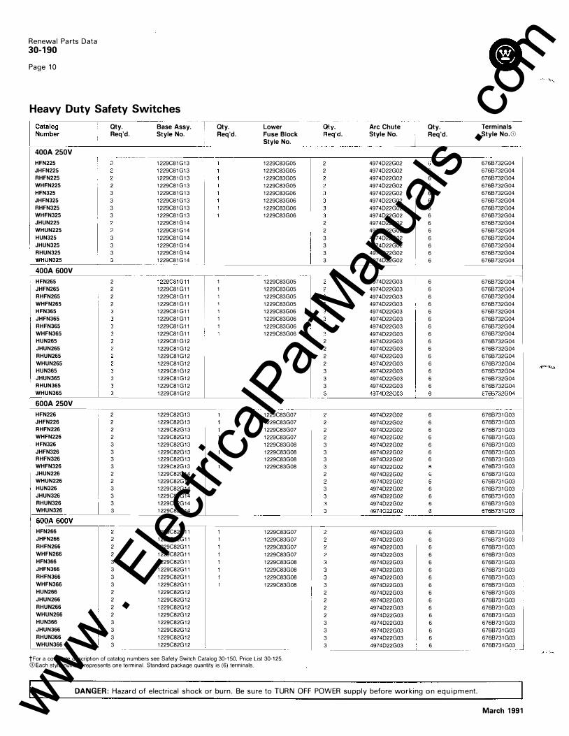
Heavy Duty Safety Switches Qty. Req'd.
Base Assy. Style No.
-----------------------------400A 250V
r aty. Req'd.
Lower Fuse Block Style No.
Arc Chute s:I�J
Qty. Req'd.
Terminals I Style No.G:J 1
---- ------------- ----�--- ---------- ------�-------------------------,-----------
HFN225 JHFN225 RHFN225 WHFN225 HFN325 JHFN325 RHFN325 WHFN325 JHUN225 WHUN225
2 3 3 3 3
HUN325 3 JHUN325 3 RHUN325 3 WHUN_�3�2�5 ____ _L_�3--
400A 600V HFN265 JHFN265 RHFN265 WHFN265 HFN365 JHFN365 RHFN365 WHFN365 HUN265 JHUN265 RHUN265 WHUN265 HUN365 JHUN365 RHUN365 WHUN365
600A 250V
2 2 2 2
1229C81 813 1229C81 813 1229C81813 1229C81813 1229C81813 1229C81813 1229C81813 1229C81813 1229C81814 1229C81G14 1229C81814 1229C81814 1229C81814 1229C81814
1229c_
s_
18_1_1
_
T 1::
1
1229C81811 1229C81811 1229C81G11 1229C81811 1229C81811 1229C81811 I 1 1229C81811 1229C81812 1229C81812 1229C81812 1229C81812 1229C81812 1229C81812 1229C81812 1229C81812
1229C83805 1229C83805 1229C83805 1229C83805 1229C83806 1229C83806 1229C83806 1229C83806
1229C83805 1229C83805 1229C83805 1229C83805 1229C83806 1229C83806 1229C83806 1229C83806
1229C83807 1229C83807 1229C83807 1229C83807 1229C83808 1229C83808 1229C83G08 1229C83G08
2 2
2 2 3 3 3 3
4974022802 4974022802 4974022802 4974022802 4974022802 4974022802 4974022802 4974022802 4974022802 4974022802 4974022802 4974022802 4974022802 4974022802
6 6 6 6 6 6 6 6 6 6 6 6 6
6766732804 6766732804 6766732804 6766732804 6766732804 6766732G04 6766732804 6766732804 6766732804 6766732804 6766732804 6766732804 6766732G04 6766732804
I 4974022803 6 6766732G0;-1 497 4022803 6 6766732804 497 4D22G03 6 6766732804 4974022803 6 6766732804 497 4022803 6 6766732804 497 4022803 6 6766732804 497 4022803 6 6766732G04 497 4022803 6 6766732804
2 4974022803 6 6766732804 2 497 4022803 6 6766732804 2 497 4022803 6 6766732804 2 497 4022803 6 6766732804 3 497 4022803 6 6766732804 3 497 4022803 6 6766732804 3 497 4022803 6 6766732G04 3
______ 4�9 _74� 0�2� 2�8�03��-� 6 _______
6_ 766732804
2 2 2 3 3 3 3 2
3
4974022802 6 6766731803 4974D22G02 6 6766731803 4974022802 6 6766731803 4974022802 6 6766731803 4974022802 6 6766731803 4974022802 6 6766731803 4974D22G02 6 6766731G03 497 4D22G02 6766731 G03 497 4D22G02 6766731 803 4974022802 6766731803 497 4022802 6 6766731 G03 4974D22G02 6 6766731G03 4974022802 6 6766731803
HFN226 JHFN226 RHFN226 WHFN226 HFN326 JHFN326 RHFN326 WHFN326 JHUN226 WHUN226 HUN326 JHUN326 RHUN326 WHUN326 I
2 2 2 2 3 3 3 3 2 2 3 3 3 3
1229C82813 1229C82813 1229C82813 1229C82813 1229C82813 1229C82813 1229C82G13 1229C82G13 1229C82814 1229C82814 1229C82814 1229C82814 1229C82814 1229C82814
____ __]________ 4974�2_9()� __ --��-----=-67�6�6�7�31�8::c0�3'------l
�OA600V HFN266 JHFN266 RHFN266 WHFN266 HFN366 JHFN366 RHFN366 WHFN366 HUN266 JHUN266 RHUN266 WHUN266 HUN366 JHUN366 RHUN366 WHUN366
2 2 2 3 3 3 3 2 2 2 2 3 3 3 3
1229C82811 1229C82811 1229C82811 1229C82811 1229C82811 1229C82811 1229C82811 1229C82811 1229C82812 1229C82812 1229C82812 1229C82812 1229C82812 1229C82G12 1229C82812 1229C82G12
1229C83807 1229C83807 1229C83807 1229C83807 1229C83808 1229C83808 1229C83808 1229C83808
tFor a complete description of catalog numbers see Safety Switch Catalog 30-150, Price List 30-125. G:JEach style number represents one terminal. Standard package quantity is (6) terminals.
3 2 2 2 2 3 3 3 3
4974022803 4974022803 4974022803 4974022803 4974022803 4974022803 4974022803 4974022803 4974022803 4974022803 4974022803 4974022803 4974022803 4974022803 4974022803 4974022803
6 6 6 6 6 6 6 6 6 6 6 6 6 6 6 6
DANGER: Hazard of electrical shock or burn. Be sure to TURN OFF POWER supply before working on equipment.
6766731803 6766731803 6766731803 6766731803 6766731803 6766731803 6766731803 6766731803 6766731803 6766731803 6766731803 6766731803 6766731803 6766731803 6766731803 6766731803
March 1991 www . El
ectric
alPar
tMan
uals
. com

Renewal Parts Data 30-190
Page 11
Heavy Duty Safety Switches
I
Catalog Number
Qty. Req'd.
Upper Qty. Base Assy. Req'd. Style_No._ _ _ �--
--
-
Lower Fuse Block Style No.
Qty. Req'd.
Arc Chute Style No. jl
·------- -
f BOOA 2SOV: - --T ! HFN327, RHFN327. L�N327, RHUNJ27
3 3
1229CB4807 1229C84808
1229C86808 --
-
---
-
�- -
66-
--4974022802
1229C86808 I _ _ 6_____ 4974022802 ----------------
-���-I BOOA 600V I HFN367
RHFN367 HUN367 RHUN367
1200A 250V HUN328, RHUN328 �-----------
1200A 600V
3 3 3 � HFN3
.
2a:-R
.
-HFN328 .1 -----,--------
1 HFN368 I ! RHFN368 I ���;�� -------
3 3 3 3
1229C84805 1229CB4805 1229C84806 1229C84806
1229CB5807 1229C85808
1229C85805 1229C85805 1229C85806 1229C85806
L
1229C86808 1229C86808
1229C86810 1229C86810
::::�:: J Part No�-� Description
-- ------,
-------- j Spring_K_
i_:_t __ _ 481-050-01 30A GO Mechanism Spring and Lever Kit 481-050-02 60A GO Mechanism Spring and Lever Kit 481-050-03 100A GO Mechanism Spring and Lever Kit 481-050-04 200A GO Mechanism Spring and Lever Kit 481-050-05 30A HD Mechanism Spring and Lever Kit 481-050-06 30/60A HD Mechanism Spring and Lever Kit 481-050-07 ' 1 OOA HD Mechanism Spring and Lever Kit 481-050-08 200A HD Mechanism Spring and Lever Kit
1- Gasket Kit ·����
I 481=050-09 30/60A Gasketing (1 Roll) 481-050-10 100/200A Gasketing (1 Roll) 481-050-11 1 400/600A Gasketing (1 Roll) �1_-050-12 L�00/1_200A Gasketing (1 Roll)
Latch Kit
481-050-13 481-050-14 481-050-15
30/60A Suitcase Latch 1 00/200A Suitcase Latch 400/600A Suitcase Latch
For Further Information Catalog 25-000 Price List 30-125 Catalog 30-150 Mini Residential Contractors SA-11668A SA-11767 Safety Switches
-1
tFor a complete description of catalog numbers see Safety Switch Catalog 30-150, Pnce List 30·125. G) Each style number represents one terminal. Standard package quantity IS (6) terminals.
6 6 6
6
4974022803 4974022803 4974022803 4974022803
4974022802 4974022802
4974022803 4974022803 4974022803 4974022803
Qty. Req'd.
T�rminals l Style No. G)
7528680802 7528680802
I
-----------------
----
6 6 6 6
6
7528680802 7528680802 7528680802 7528680802
------
-�--
-
6768731803 6768731803
6768731803 6768731803 6768731803 6768731803
DANGER: Hazard of electrical shock or burn. Be sure to TURN OFF POWER supply before working on equipment.
March 1991 www . El
ectric
alPar
tMan
uals
. com
Renewal Parts Data 30-190
Page 12
Westinghouse Electric Corporation Distribution and Control Business Unit Standard Distribution Products Division Pittsburgh, Pennsylvania, U.S.A. 15220
Distributed by:
Printed in U.S.A.
March 1991 www . El
ectric
alPar
tMan
uals
. com