Embed Size (px)
DESCRIPTION
Link 16 Joint Tactical Information Distribution System Multifunctional Information Distribution System (JTIDS / MIDS) Spectrum Issues Tutorial Information. PJCC 2012 26 July 2012 Honolulu. - PowerPoint PPT Presentation
Citation preview

PJCC 201226 July 2012
Honolulu
This information is furnished upon the condition that it or knowledge of its possession will not be released to any nation outside of those participating in the JTIDS/MIDS Multi-National Working Group (MNWG) without specific authority of and benefit to a MNWG member; that individual or corporate rights originating in the information whether patented or not, will be respected and; that the information will be provided the same degree of security afforded to the providing MNWGs member government organization. This brief is presented on behalf of the US MNWG Head of Delegation.
Link 16Joint Tactical Information Distribution System
Multifunctional Information Distribution System(JTIDS / MIDS)
Spectrum Issues Tutorial Information

Tutorial Information Agenda
1. Introduction
Opening Remarks
2. Background
Link 16 Description
Frequency Spectrum Implications
3. Link 16 Compatibility in the Frequency Band
Link 16 Waveform Design Considerations
Link 16 and Aviation Systems Analyses and Test Programmes
4. MNWG Common Frequency Clearance Criteria
5. US Frequency Remapping Capability
6. Link 16 Terminal EMC Protection Features
7. Acronyms

Link 16
Description and Frequency Band Implications
Background

Background
• Link 16 Description– Link 16 JTIDS/MIDS System Description and Functions
– Equipment/Terminals
– Example Platforms
– Time Slot Duty Factor
• The 960-1215 MHz Frequency Band Spectrum Implications– National Frequency Clearance Agreements
– Frequency Sharing 960 – 1215 MHz Band
– Surveillance, Navigational Aides and Other Aviation Systems
JTIDS MIDS
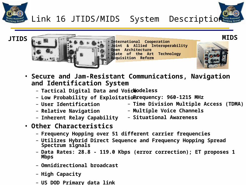
• Secure and Jam-Resistant Communications, Navigation and Identification System
– Tactical Digital Data and Voice– Low Probability of Exploitation– User Identification – Relative Navigation – Inherent Relay Capability
• Other Characteristics– Frequency Hopping over 51 different carrier frequencies– Utilizes Hybrid Direct Sequence and Frequency Hopping Spread Spectrum signals– Data Rates: 28.8 - 119.0 Kbps (error correction); ET proposes 1 Mbps
– Omnidirectional broadcast
– High Capacity
– US DOD Primary data link
– Many US allies also utilize Link 16
– Nodeless – Frequency: 960-1215 MHz– Time Division Multiple Access (TDMA)– Multiple Voice Channels– Situational Awareness
Link 16 JTIDS/MIDS System Description
• International Cooperation• Joint & Allied Interoperability• Open Architecture• State of the Art Technology• Acquisition Reform

Link 16 EQUIPMENT/Terminals*
*Not to Scale
CLASS 2H (SHIP/GROUND/AIR)
1.35 CU. FT 1040 WATTS
1.56 CU. FT
200 WATTS
180 LBS.
HIGH POWER AMPLIFIER GROUP
CLASS 2RT DPG
1981
CLASS 2M
U.S. ARMY 1.25 CU. FT 200 WATTS
90 LBS.
1990
MIDS LVT1
U.S. AND EUROPEAN AIRCRAFT 0.6 CU. FT
200 WATTS 64 LBS.
CLASS 2H
USN SHIPS
1 kW
840 LBS.
F22 ICNIA
MIDS - JTR
Army MIDS LVT2
200 Watts
AMF
JTRS
The Future
USAF MIDS LVT340 – 80 Watts
JSF
MIDS On ShipUSN Ships1 KW
UK AN/URC-138
CLASS 1
SCWDL
SDB
STT

RIVET JOINT/COMBAT SENT
US NAVY CG
ASOC
FR E-3
USAF JOINT STARSUSAFAOC
UK E-3
MDAPATRIOT
MDATHAAD
USMC TAOM
US ARMYFAAD
USAFCRC MDA
CORPS SAM
USAF JTIDSMODULE
NATO CRC
NATO E-3
US NAVY E-2C
US NAVYCARRIER
COMPASS CALL/SENIOR SCOUT
USAF F-15
UK TORNADOUSAF E-3
USMC JTIDSMODULE
MIDS is the Third Generation Link-16 Terminal
JTIDS - First and Second Generation Link-16 Terminals
Link-16
Example Link-16 PlatformsPresent and Future
F-18
F22
B2EUROFIGHTER(Typhoon) USN EA-6B
F-35
B1
UCAVUSN SH-60F-16Mirage

Link 16 System Architecture
High CapacityAntijam
SecureExtended LOS
Flexible
Link 16Transmit capacity varies from unit to unit.More turns means more capacity.
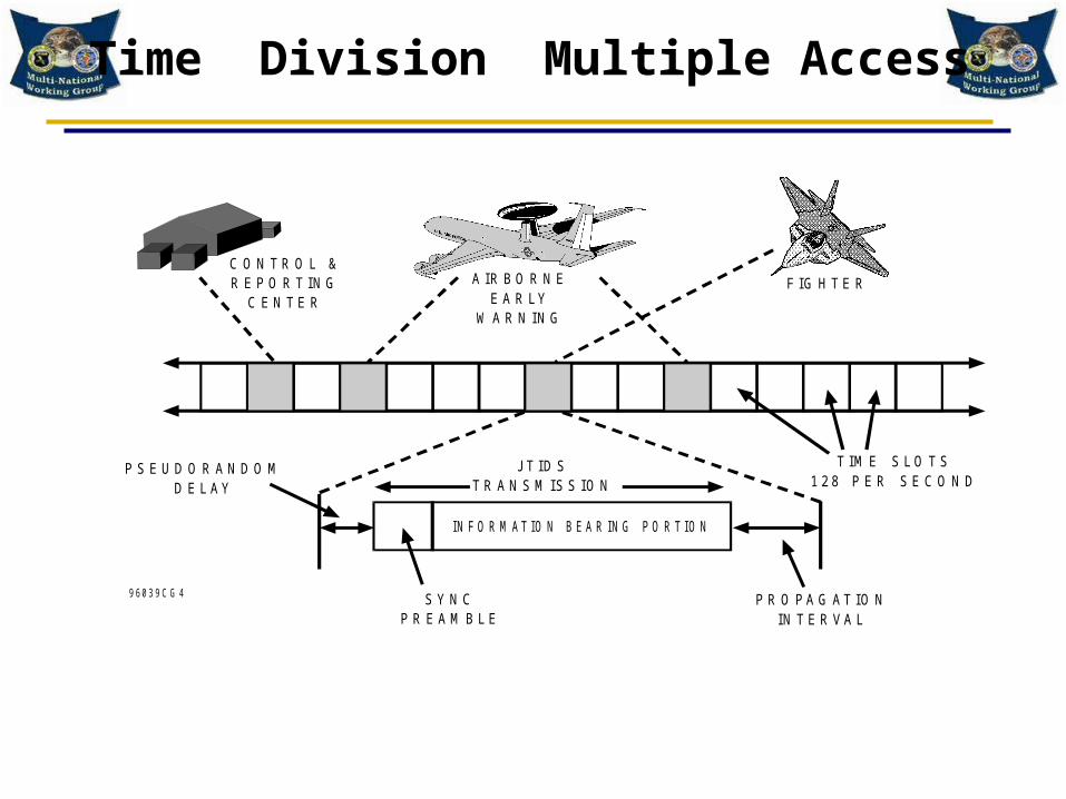
Time Division Multiple Access
9 60 3 9 C G 4
P S E U D O R A N D O MD E L AY
J T ID ST R A N S M IS S IO N
IN F O R M AT IO N B E A R IN G P O R T IO N
T IM E S L O T S1 2 8 P E R S E C O N D
P R O PA G AT IO NIN T E R VA L
S Y N CP R E A M B L E
C O N T R O L &R E P O R T IN G
C E N T E R
A IR B O R N EE A R LY
W A R N IN G
F IG H T E R

JTIDS / MIDS TDMA ARCHITECTURE
• 12 SECONDS PER FRAME
• 1536 TIME SLOTS/FRAME (EACH NET)
• 127 NETS
• TERMINAL RESTRICTED TO ONE NET EACH TIME SLOT
• IN A TIME SLOT TERMINAL CAN TRANSMIT OR RECEIVE - NOT BOTH
1 2 3 4 5 6
JIT
TE
R
SY
NC
MESSAGE PROP-AGATION
7
126
0
NE
TS
TIME SLOTS 7.8125 msTIME SLOT

TIME SLOT / SIGNAL STRUCTURE
9 60 3 9 C G 5
I N F O R M A T I O N B E A R I N G P O R T I O N
P R O P A G A T I O NI N T E R V A L
2 5 8 O R 4 4 4 P U L S ES E Q U E N C E
7 . 8 1 2 5 m s e c
P U L S E T R A I NS P R E A D
S P E C T R U M
F R E Q U E N C YH O P P E D
P S E U D O N O I S E M O D U L A T E D P U L S E S
6 . 6 s 6 . 4 s
1 3 s e c 1 3 s e c
T I M E S L O T
P S E U D O -R A N D O M
D E L A YP R E -
A M B L E
f1 f
2f
3f
4f
X
fY
fX
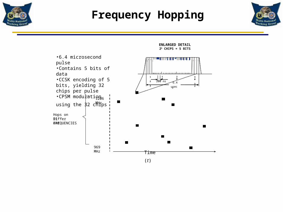
JTIDS PULSE6.4 sec
5 BITSENCODED IN 32
CHIPS

TRANSMISSION PULSE
• 6.4 μs PULSE
• CONTAINS 5 BITS OF DATA
• CPSM 5 BITS YIELDING 32 CHIPS PER PULSE
Hops on 51 Different FREQUENCIES
1206 MHz
969 MHz
TIME
200 nsec
25 CHIPS =
5 BITS
1 2 3
10
20
30 326.4
use
+ +
_ +
+
-
-
ENLARGED DETAIL

JTIDS Single Carrier Spectrum
10 dB / div
CENTER 969.27 MHz
RES BW 300 kHz VBW 300 kHz SWP 20 ms
SPAN 50.00 MHz
REF 0 dBm

Dedicated Access
• Most access assignments are dedicated.
• With dedicated access, a single user transmits data, all other users receive the data.

Multi-net
• Multi-netting involves mutually exclusive groups performing different functions using the same time slots (but with different hopping patterns).
• Decision to use multi-net made during the initial network design build. Multi-net is not an operator selectable feature.
1
0
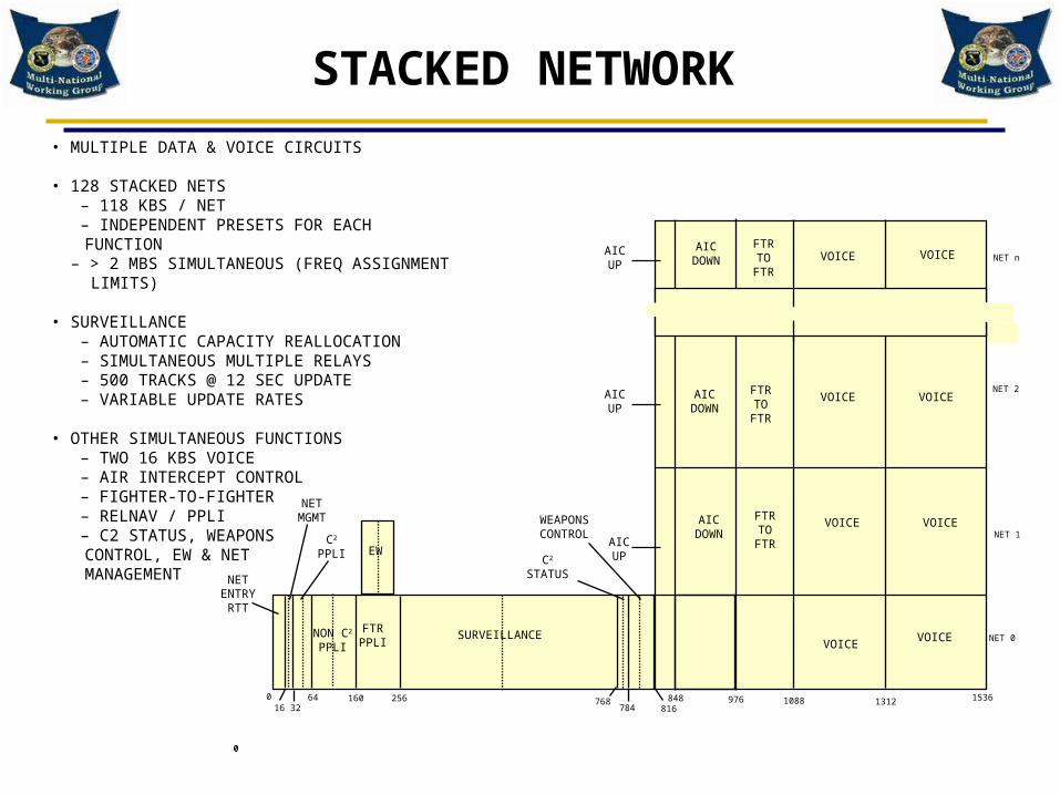
STACKED NETWORK
• MULTIPLE DATA & VOICE CIRCUITS
• 128 STACKED NETS – 118 KBS / NET – INDEPENDENT PRESETS FOR EACH FUNCTION – > 2 MBS SIMULTANEOUS (FREQ ASSIGNMENT LIMITS)
• SURVEILLANCE – AUTOMATIC CAPACITY REALLOCATION – SIMULTANEOUS MULTIPLE RELAYS – 500 TRACKS @ 12 SEC UPDATE – VARIABLE UPDATE RATES
• OTHER SIMULTANEOUS FUNCTIONS – TWO 16 KBS VOICE – AIR INTERCEPT CONTROL – FIGHTER-TO-FIGHTER – RELNAV / PPLI – C2 STATUS, WEAPONS
CONTROL, EW & NET MANAGEMENT
0
AIC UP
AIC DOW
N
FTR TO FTR
VOICE VOICE
AIC DOWN
FTR TO FTR
VOICE VOICEAIC UP
AIC UP
AIC DOWN
FTR TO FTR
VOICE VOICE
VOICEVOICE
WEAPONS CONTROL
C2
STATUS
EW
SURVEILLANCEFTR PPLI
C2
PPLI
NET MGMT
NET ENTRY RTT
016 32
64 160 256 768784 816
848 976 1088 1312 1536
NET 0
NET 1
NET 2
NET n
NON C2
PPLI

CONTENTION
• Transmitters use the same time slots.
• Separate ‘protocol” used to minimize message “conflicts”– push-to-talk– over subscribed pool– operational control
• Receivers hear only the closest transmitter.

JTIDS / MIDS Time Slot Duty Factor
• Time Slot Duty Factor (TSDF) – Defined as the total percentage of JTIDS/MIDS transmission pulses over a 12 second period (out
of 396,288 pulses total) within a specific geographic area. – Factor is derived from total number of possible pulses in a time slot (72, 258, or 444) times the
number of time slots where JTIDS/MIDS terminals can possibly transmit in the 12 second period (frame).
– Two numbers are typically used. The first number is the TSDF for the entire exercise within the geographic area, while the second number is the TSDF of the highest TSDF JTIDS / MIDS platform.
• Geographic area is a radius around each platform
– 100/50 nomenclature represents: • 100% TSDF in the exercise or in a geographic area• 50% TSDF for the highest TSDF platform
– A third number is also sometimes used to represent the TSDF in a second tier geographic area. For example, 100/50/(300) represents:
• 100% TSDF in the exercise or in a geographic area of 100 NM• 50% TSDF for the highest TSDF platform• 300% between 100 NM and 200 NM
(300% TSDF)
(100% TSDF)100 NM
200 nmi
(50% TSDF )

The 960 - 1215 MHz Frequency BandSpectrum Implications
• Internationally allocated (protected) world wide for the Aeronautical Radionavigation Service (ARNS) from 960-1215 MHz
• Allocation to the Radionavigation Satellite Service (RNSS) from 1164 -1215 MHz
• Allocation to the Aeronautical Mobile (Route) Service [AMR(S)] from 960-1164 MHz
• Band usually administered by civil aviation agencies worldwide
• JTIDS/MIDS operates in the band as a guest– Non harmful interference basis to the primary ARNS systems
• ITU Radio Regulation RR-4.4*
• Special national frequency clearance agreements– To date there are 32 different nations
– JTIDS/MIDS designed to be compatible with existing ARNS systems• More than twenty year interagency (civil and military) electromagnetic compatibility test
program
• New aviation systems being implemented and others being explored for this band* ITU Radio Regulation RR-4.4 permits state operation of radio stations on a non-interference basis without protection.

Why an FCA?
• Link 16 non-interference basis world wide– Not in accordance with table of allocations
– ITU Radio Regulation RR-4.4
• Need special agreement with civil aviation authorities to operate Link 16
• Frequency Clearance Agreement– Design characteristics
– Operational restrictions
– Coordination to meet requirements
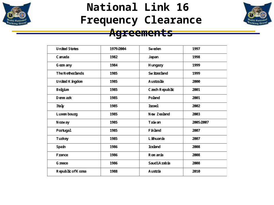
National Link 16 Frequency Clearance Agreements
United States 1979/2004 Sweden 1997
Canada 1982 Japan 1998
Germany 1984 Hungary 1999
The Netherlands 1985 Switzerland 1999
United Kingdom 1985 Australia 2000
Belgium 1985 Czech Republic 2001
Denmark 1985 Poland 2001
Italy 1985 Israel 2002
Luxembourg 1985 New Zealand 2003
Norway 1985 Taiwan 2005/2007
Portugal 1985 Finland 2007
Turkey 1985 Lithuania 2007
Spain 1986 Iceland 2008
France 1986 Romania 2008
Greece 1986 Saudi Arabia 2008
Republic of Korea 1988 Austria 2010

GPS L5, Galileo E5A, QZSS, SBAS (WAAS, SDCM, EGNOS, GAGAN, MSAS, NigComSAT): 1176.45 12 MHz
GLONASS L3: 1198.55 – 1204.88 MHzGLONASS L5: 1176.45 +/- 12 MHz Galileo E5B: 1207-10 MHz to 1207+4 MHz
COMPASS: 1195 – 1219MHz
FREQUENCY SHARING960 - 1215 MHz Band
New WRC 07 AM(R)S allocation - upper frequency limit (1024 – 1164 MHz) subject to ITU analyses; UAT = Universal Access Transceiver ; R NSS = Radionavigation Satellite Service; ADS-B = Automatic Dependent Surveillance – Broadcast Mode S ES = Mode Select Extended Squitter; PSR = Primary Surveillance Radar; RSBN = Radionavigatsionnaya Sistema Blizhney Navigatsii; L-DACS = L-Band Digital Aeronautical Communication System; GSM = Global System for Mobile Communications; UMTS = Universal Mobile Telephone System
UA
T
GPS L5 / Galileo E5A/B Various SBAS /
COMPASS GLONASS L3
Mo
de
S E
S
ADS-B Systems
1090 MHz978 MHz
JTIDS / MIDSFREQUENCIES
EVERY3 MHz
JTIDS / MIDSCARRIERS
14JTIDS / MIDSCARRIERS
5JTIDS / MIDSCARRIERS
32
1030+/- 10 MHz
1090+/- 4 MHz
1215960
Allocated to the Aeronautical Radionavigation Service
Allocated to the RNSS
1164TACAN / DME CHANNELS EVERY 1 MHz
ACAS/TCAS, SSR Systems: ATCRBS, MODE S, IFF, MLAT/WAM, ASMGCS
AM(R)S Systems
Global NavigationSatellite Systems
Allocated to Aeronautical Mobile (Route) Service [AM(R)S]*
969 1008 1053 1065 1113 1206
Inte
rro
gat
ion
Rep
ly
Proposed AM(R)S Solutions:
L-DACS 1:FDD/OFDMOrigin: B-AMC/P34
985.5L-DACS 2:TDD CPSFK/GMSK Origin: AMACS/LDL VDL Mode 3/ UAT
960 MHz 975 MHz
G/A ULB-AMC
A/G RL
A/G & G/A TMA 960-965 MHz; A/A 965-972 MHz; A/G & G/A En route 972-975 MHz
AMACS
1008.5 1048.5 1071.5
RSBN (Non-ICAO)
939.6 MHz 1000.5 MHzG/A Transponder
GSM/UMTS
< 959.8 MHz
PSR 1215 –1400 MHz
IRNSS: 1176.45 MHz
An Unmanned Aircraft System (UAS) Control and Non-Payload Communications (CNPC) data link system operating within the AM(R)S may also utilize the 960-1164 MHz band. Most likely 960-975 MHz
EGNOS: European Geostationary Navigation Overlay Service; GAGAN: GPS Aided GEO Augmented Navigation; GLONASS: Global Navigation Satellite System; IRNSS: India Regional Satellite System; MSAS: MTSAT Satellite Based Augmentation System; QZSS: Quasi-Zenith Satellite System; NigComSAT: Nigerian Communications Satellite
Index:

Link 16 Carrier Frequencies
Carrier Number Center Frequency (MHz)
Carrier Number Center Frequency (MHz)
0 969 26 1,1341 972 27 1,1372 975 28 1,1403 978 29 1,1434 981 30 1,1465 984 31 1,1496 987 32 1,1527 990 33 1,1558 993 34 1,1589 996 35 1,16110 999 36 1,16411 1,002 37 1,16712 1,005 38 1,17013 1,008 39 1,17314 1,053 40 1,17615 1,056 41 1,17916 1,059 42 1,18217 1,062 43 1,18518 1,065 44 1,18819 1,113 45 1,19120 1,116 46 1,19421 1,119 47 1,19722 1,122 48 1,20023 1,125 49 1,20324 1,128 50 1,20625 1,131

9 6 0 4 0 C G 8
Composite Spectrum of the JTIDS Carriers

L-Band Surveillance, Navigational Aides and ARNS / Aviation Systems
ACASCollision AvoidanceADS-B(UAT or 1090 ES)AM(R)S Air to Air*
Secondary Surveillance Radar(SSR) Beacon Interrogator• Mode S Sensor, ATCRBS or IFF
Interrogation 1030 MHz
Reply 1090 MHz:
ID and Altitude
Inte
rrog
atio
n
TACAN/Distance Measuring Equipment• DME/N associated with VOR and ILS• DME/P associated with VOR and MLS• TACAN range and bearing
Rep
ly:
For
TO
A
and
Dx
Cal
cula
tion
• TACAN/DME Interrogator• SSR Transponder
AM(R)S A/G FL and RL*
Unmanned AircraftSystems (UAS)CNPC*
MLAT / HMU / WAM*
* Possible Future Capability

GNSS Example:GPS and Augmentation Systems
GPS Satellites
GPS L1 & L5Non-Precision Landing
WAAS L1 & L5CAT I Precision Landing
WAAS GEOSatellite*
LAAS L1 & L5CAT II/III Precision Landing 4 R
Wide Area Reference Station (WRS)
WRS
GPS Satellites
Differential GPS
4 L
* Other GEO augmentation satellites include EGNOS, MSAS, GAGAN
GPS Master Control Station

TACAN/DME Frequency Plan
28
1088 (1Y)
X)
1213 (126X)
X)
962 (1X)
X)
1024 (63X)
X)
1151 (64X)
X)
1150 (63Y)
X)
1025 (64Y)
X)
1087 (126Y)
X)
Reply Frequencies (Ground
Transmitters)
Interrogation Frequencies (Airborne Transmitters)
National Allotment Channels 962-977 MHz (1X – 16X)
used for Military Shipboard and Land TACAN Ground Beacons Tx

TACAN / DMEINFORMATION
• General Information– The Tactical Air Navigation (TACAN) system provides slant range and
bearing information to pilots
– The Distance Measuring Equipment (DME) system provides only slant range
– Both systems consist of airborne interrogators and ground –based transponders (beacons)
• Used for an aircraft to determine position relative to fixed locations (Beacons)
• Two modes (x and y) of operation available
• Measurement Information– Range from beacon derived by subtracting the specified beacon reply
delay time from the round – trip propagation time
– Bearing from beacon derived by detecting amplitude modulation on reply pulse train and comparing it to reference bursts
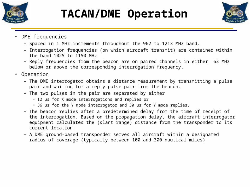
TACAN/DME Operation
• DME frequencies– Spaced in 1 MHz increments throughout the 962 to 1213 MHz band.– Interrogation frequencies (on which aircraft transmit) are contained within the band 1025 to 1150 MHz– Reply frequencies from the beacon are on paired channels in either 63 MHz below or above the
corresponding interrogation frequency. • Operation
– The DME interrogator obtains a distance measurement by transmitting a pulse pair and waiting for a reply pulse pair from the beacon.
– The two pulses in the pair are separated by either • 12 us for X mode interrogations and replies or • 36 us for the Y mode interrogator and 30 us for Y mode replies.
– The beacon replies after a predetermined delay from the time of receipt of the interrogation. Based on the propagation delay, the aircraft interrogator equipment calculates the (slant range) distance from the transponder to its current location.
– A DME ground-based transponder serves all aircraft within a designated radius of coverage (typically between 100 and 300 nautical miles)

TACAN/DMECompatibility Implications
TACAN/DME Operates on fixed frequencies in the same
frequency band as Link-16
Ground-Based
TACAN / DME Beacons
Airborne TACAN / DME Interrogators
Time
TACAN/DME communicates using pulse-pairs with a
fixed spacing
If the system detects two pulses with the proper spacing (within the
receiver decoder window) and within the expected signal level range, it declares a valid decode

SSR Description
• Provides Air Traffic Control facilities with aircraft location and identification information
• Consists of ground beacon interrogators and airborne transponders
• Several SSR interrogation modes are available• Examples include:
– Air Traffic Control Radar Beacon System (ATCRBS)– Mode Select (Mode S)– Identification Friend or Foe (IFF)
• Link 16 does not transmit carriers in the 1030 MHz or 1090 MHz SSR bands

SSR Interrogator Description
• Transmits interrogations at a fixed rate at 1030 MHz• Has rotating directional antenna with narrow horizontal
beamwidth and fan shaped vertical beamwidth• Receives aircraft transponder replies on 1090 MHz• Determines azimuth, range and identification of
aircraft• Determines altitude on altimeter equipped aircraft• Uses pulse position modulation

SSR Transponder Description
• Receives interrogations at 1030 MHz• Has omnidirectional antenna • Provides identification (Mode 3/A) and altitude level
(Mode C) depending on interrogation mode• Transmits replies on 1090 MHz• Uses pulse position modulation

Link 16 Compatibilityin the
Frequency Band

Link 16 Compatibility in the Frequency Band
• Link 16 Frequency Band Selection• Waveform Design Considerations• Test Program Summaries• Link 16 Operational Controls for EMC
– Common Frequency Clearance Criteria
• Compatibility with New Aviation Systems Planned To Opereate in the Frequency Band
• Link 16 Terminal EMC Features

Frequency Band Selection
• Design requirements– Omnidirectional broadcast
– Frequency has to be less than 2500 MHz
– High jamming resistance requires at least 200 MHz bandwidth
– frequency has to be ≥ 400 MHz
• Candidate bands with these systems were rejected due to EMC considerations– Pulsed radars
– Television
– Satellite downlink
– Microwave relay
– Radio astronomy

Frequency Band Selection( Continued )
CANDIDATE FREQUENCY BANDS
AVAILABLE
BAND BANDWIDTH SERVICE
MHz MHz
960 – 1215 197 AERONAUTICAL RADIONAVIGATION
1435 – 1535 75 FIXED, MOBILE
1535 – 1660 63 AERONAUTICAL RADIONAVIGATION
1710 – 1850 124 MOBILE
2300 – 2450 135 RADIOLOCATION

Frequency Band Selection( Continued )
• Candidate bands were examined with respect to
– EMC
– International usage
– Available bandwidth
• It was concluded that the 960 – 1215 MHz band was the best choice

Waveform Design
• From beginning of design, EMC with ATC systems was considered– Over 100 waveforms investigated for compatibility
– Eventually chose one to US FAA and DOD satisfaction
• Compatibility with TACAN/DME and SSR / ATCRBS / IFF / TCAS
• Was a multiagency effort in the US– NTIA
– FAA
– DOD
– RTCA
– ARINC– FCC– MITRE– ECAC/JSC

Compatibility withTACAN/DME and SSR Receivers
• TACAN / DME solution– Minimize the number of decodes
• A 6.4 microsecond pulse width chosen to prevent single pulse decodes
• Adjacent JTIDS / MIDS pulses transmitted uniformly over the band – Psuedo randomly
– Frequencies of adjacent pulses at least 30 MHz apart
– Minimize the number of pulses received• Waveform has maximum aggregate RF duty cycle of 21 % (TSDF = 100%)
– ( 258 Pulses / Time Slot X 128 Time Slots / Sec X 6.4 microseconds)
• Because of fast spectrum roll off, only 7 out of 51 frequencies will typically be detected at foreground levels which reduces effective RF duty cycle To 2.9% ( 7 / 51 X 21 )
• SSR solution– JTIDS pulses eliminated by two large spectrum notches
• 45 MHz around 1030 MHz
• 48 MHz around 1090 MHz
– Pulse spectrum controlled down to -60 dBc at 15 MHz away

Compatibility Design Objectives TACAN / DME Beacons
• Minimize the number of decodes and pulses detected – Decodes can reduce traffic handling capability
to less than 100 aircraft• 27 Decodes = 1 % reduction
– Single pulses interrupt receiver processing and reduce reply efficiency
• Requirement = 70 %
Link 16 Ground Site
TACAN/DME BeaconWant Pr <= -33 dBm
Detected Capability

Compatibility Design Objectives TACAN / DME Interrogators
• Minimize the number of decodes and pulses detected– Decodes can capture automatic gain control
– Equipment can tolerate at least 200 decodes / sec at power levels 8 dB above the desired level
– Single pulses can interrupt receiver processing and potentially reduce reply efficiency
• Requirement is to tolerate 6000 pulses / sec at power levels 30 dB above desired level
1000 ft

Compatibility Design Objectives Secondary Surveillance RADAR Receiver
• SSR Ground Interrogators– IFF, ATCRBS or Mode S Sensors
• Minimize the number of pulses detected– Single pulses can interrupt receiver processing
and potentially cause reduction in reply efficiency
• Reduction must be minimized
• SSR ATC is the most important safety of flight requirement
Link 16 Ground Site
SSR ATCRBS Ground Interrogator
Want Pr < = -20 dBm
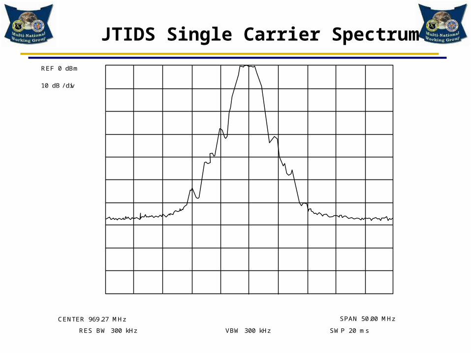
JTIDS Single Carrier Spectrum
10 dB / div
CENTER 969.27 MHz
RES BW 300 kHz VBW 300 kHz SWP 20 ms
SPAN 50.00 MHz
REF 0 dBm

9 6 0 4 0 C G 8
Composite Spectrum of the JTIDS Carriers
Frequency Hopping
Time (t)
Hops on 51 Different FREQUENCIES
1206 MHz
969 MHz
•6.4 microsecond pulse•Contains 5 bits of data•CCSK encoding of 5 bits, yielding 32 chips per pulse•CPSM modulation using
the 32 chips nsec
1
2
3
10
20
30
32
++
_
+ + - -
200 ns
1
2
3
10
20
30
32
6.4
usec
++
_
+ + - -
ENLARGED DETAIL25 CHIPS = 5 BITS

Test Program Summary
Dates Nation Tests Outcome
1969-1974 US Over a hundred initial waveform designs analyzed for EMC with TACAN/DME interrogators and beacons and SSR interrogators and transponders
100 candidate waveforms reduced to 10
1974 US Hughes Signal Generator tests on TACAN/DME beacons and interrogators with FAA participation
10 candidate waveforms reduced to 2
1974-1975 US FAA sponsored tests of TACAN/DME and ATCRBS systems
Single waveform chosen. Same waveform used in all JTIDS/MIDS terminals in use today.
1976-1978 US TACAN/DME and SSR system bench and flight tests
JTIDS/MIDS could coexist with existing ATC. 1979 First US operational frequency clearance at 40/20 TSDF. US 224 Footnote created
1979-1984 UK CAA and MOD ATC tests Support for deployment of JTIDS on various UK platforms
1980-1982 Germany ATC tests performed by MOD, MOPT and MOT to support NATO requirements
Support for deployment of NATO JTIDS
1984-1987 US Phase I TACAN/DME, DME/P Mode S and ATCRBS testing with 100/50 environments
NTIA initial support for 100/50 and development of risk assessment as guidance for completing T&E program
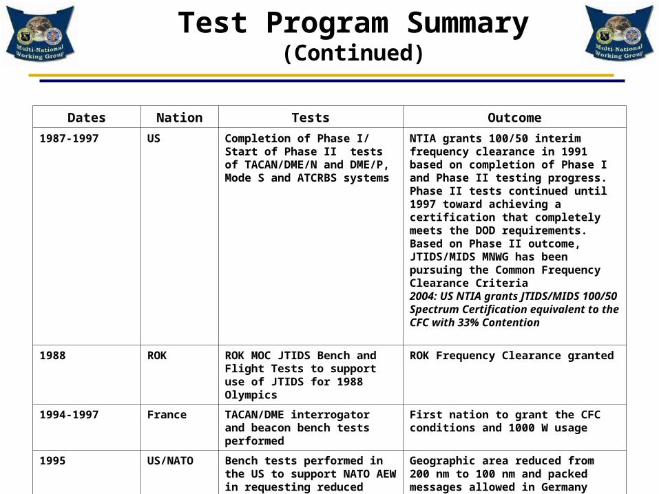
Test Program Summary(Continued)
Dates Nation Tests Outcome
1987-1997 US Completion of Phase I/ Start of Phase II tests of TACAN/DME/N and DME/P, Mode S and ATCRBS systems
NTIA grants 100/50 interim frequency clearance in 1991 based on completion of Phase I and Phase II testing progress. Phase II tests continued until 1997 toward achieving a certification that completely meets the DOD requirements.Based on Phase II outcome, JTIDS/MIDS MNWG has been pursuing the Common Frequency Clearance Criteria2004: US NTIA grants JTIDS/MIDS 100/50 Spectrum Certification equivalent to the CFC with 33% Contention
1988 ROK ROK MOC JTIDS Bench and Flight Tests to support use of JTIDS for 1988 Olympics
ROK Frequency Clearance granted
1994-1997 France TACAN/DME interrogator and beacon bench tests performed
First nation to grant the CFC conditions and 1000 W usage
1995 US/NATO Bench tests performed in the US to support NATO AEW in requesting reduced geographic area in Europe
Geographic area reduced from 200 nm to 100 nm and packed messages allowed in Germany

Test Program Summary(Continued)
Dates Nation Tests Outcome
1998-2004 Japan TACAN/DME interrogator and beacon bench tests performed
Frequency clearance for all of Japan granted in 1999
2003 Iceland DME Interrogator flight tests performed at 500 ft altitude; DME Beacon tests, SSR interrogator flight test, and GPS L1 operational tests performed
Results showed compatibility
2004 Italy TACAN/DME interrogator and beacon bench tests performed
Italy obtained CFC in 2007
2007 Germany DME Geographic Area Related Tests for Any Point in Space
50 NM APIS Geographic Area Accepted
2008 UK FERNO and THALES DME Beacon Tests with SDES
Based on an understanding of the SDES and the beacon load, a revised approach for the geographic area has been considered for the UK FCA.

100/50 TSDF US EMC Test Program
• As part of the spectrum support efforts for JTIDS, an EMC Test Program was performed where JTIDS was tested against ATC systems operating in the frequency band to ensure EMC– TACAN/DME/N Interrogators– TACAN/DME/N Beacons– DME/P Interrogators– DME/P Beacon– ATCRBS Interrogators– Mode S Sensor– ATCRBS and Mode S transponders– TCAS (analysis was performed based on Mode S transponder
test data)• Resulted in CFCC being granted in 2004

MNWGCommon Frequency Clearance
Criteria
Link 16 Operational ControlsCommon Frequency Clearance Criteria
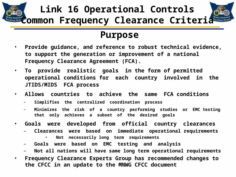
• Provide guidance, and reference to robust technical evidence, to support the generation or improvement of a national Frequency Clearance Agreement (FCA).
• To provide realistic goals in the form of permitted operational conditions for each country involved in the JTIDS/MIDS FCA process
• Allows countries to achieve the same FCA conditions– Simplifies the centralized coordination process
– Minimizes the risk of a country performing studies or EMC testing that only achieves a subset of the desired goals
• Goals were developed from official country clearances– Clearances were based on immediate operational requirements
• Not necessarily long term requirements
– Goals were based on EMC testing and analysis
– Not all nations will have same long term operational requirements
• Frequency Clearance Experts Group has recommended changes to the CFCC in an update to the MNWG CFCC document
Purpose

Link 16 Operational ControlsCommon Frequency Clearance Criteria
• The MNWG Common Frequency Clearance Criteria (CFCC) Document is a composite document
– Contained in the MNWG Notebook found on the MNWG website
– December 1996 was first version, 2007 version is the latest
– New 2012 draft being compiled by the Frequency Clearance Expert Group working under the direction of the Multi National Working Group (MNWG) Steering Committee.
– Designed to support the development of a national Frequency Clearance criteria
– Draws upon the combined experience of those nations that have carried out interference testing between MIDS/JTIDS and both Civil and Military Communication, Navigation and Surveillance (CNS) systems.
– Based on testing and technical evidence that has been used in the generation of a wide variety of national Frequency Clearance Agreements for allowing the use of Link 16 within national borders.
The Document

Link 16 Operational ControlsCommon Frequency Clearance Criteria
• The following slides describe each of the CFCC criteria conditions
• The CFCC criteria summary is followed by a test data support summary
– Every criteria is based on EMC test data
– The test data reports are available on the MNWG web site WWW.MNWG.ORG

Time Slot Duty Factor (TSDF)
• Conditions apply to transmissions by all JTIDS/MIDS terminals
– Fixed sites – Marine mobile
– Air mobile– Ground mobile
• A single JTIDS/MIDS user shall not transmit more than 50 % TSDF
– 198,144 pulses in a 12 second period
• Total TSDF in geographic area is limited to 100%
– 396,288 pulses in a 12 second period
• Note the 100% and 50% limits are not based on test results because higher TSDF was collected which did not indicate an operational problem with the ATC receivers

Transmitter Power level
• The nominal signal level of the JTIDS and MIDS terminals is limited to 200 W +1 dB
• Some countries have imposed Effective isotropic Radiated Power (EIRP) levels limits of 61 .5 dBm for ground platforms and 57.5 dBm (200 W+1 + 5.5 dB antenna gain and 2 dB line loss) for airborne platforms
• The transmitter power level limits are based on the characteristics of terminal and platforms that have been approved to operate many countries
• France has permitted the use of 1000 watts by adding additional distance restrictions (equivalent to the 7 dB increase in power level) between the Link 16 terminal and the ATC receivers

Geographic Area Of MIDS/JTIDS Operations
• The Geographic Area of JTIDS/MIDS Operations can be defined in two different ways
– Any Point in Space (APIS)
– Platform Centric (PC).
– individual administrations can identify either method in their respective frequency clearance.
• PC Geographic Area is defined as a cylinder of X Nautical Miles (NM) radius around each JTIDS/MIDS platform covering the total airspace between the highest airborne JTIDS/MIDS platform and the ground
• APIS Geographic Area is defined as a perpendicular cylinder with a radius of X nm drawn around any point in space.
• Example Geographical Areas in use include:
– United Kingdom – APIS 60% TSDF / 70nm (APIS 60/70)
– Germany – APIS 100% / 70nm (APIS 100/70)
– United States – PC 400% / 200nm and 100% / 100 nm (PC 400/200 & 100/100)

Message Packing
• Both Standard and Packed message structures
(258 and / or 444 pulse time slots) are allowed on
the condition the maximum pulse count limit
(expressed as a Geographical Area TSDF) is
maintained

Multinet
• Multinet operations are allowed
– Multinet results in overlapping time slots at the ATC
receiver
– The overlapping timeslots are on different nets

Contention
• Contention operations are allowed
– Contention results in overlapping time slots at the ATC receiver
– The overlapping timeslots are on the same nets
• Examples of network participation group (NPG) messages
that can result in contention– Initial Net Entry (INE), – Round Trip Timing – Broadcast (RTT-B)– Precise Participant Location and Identification – Broadcast (PPLI-
B), – Fighter to fighter (Contention Access)– Time Slot Reallocation (TSR) in the non-centralized mode– TSR Initial Entry– Repromulgation Relay – Conditional Paired Slot Relay (CPSR)

Geographic Separation From Ground Based TACAN/DME Beacons
• The minimum separation between any fixed site, marine mobile or ground mobile JTIDS/MIDS terminal and any ground based Tactical Air Navigation / Distance Measuring Equipment ( TACAN / DME ) Operating in the 960 to 1215 MHz band Shall be based on a received signal level of – 33 dBm ( Decibels relative to a milliwatt )
• Note the -33 dBm limits are not based on test results.
– There is higher signal level data collected which did not cause operational problems with the TACAN/DME receivers
– Separation distances corresponding to a -33 dBm received signal level were determined to be sufficient for operations
Link 16 Ground Site
TACAN/DME BeaconWant Pr <= -33 dBm

Geographic Separation From Ground Based SSR Ground Equipment
• The minimum separation between any fixed site, marine mobile or ground mobile JTIDS/MIDS
Terminal and any Air Traffic Control Radar Beacon System / Secondary Surveillance Radar (ATCRBS / SSR) ground equipment operating in the 960 to 1215 MHz band shall be based on a received signal level of – 20 dBm
Link 16 Ground Site
SSR ATCRBS Ground InterrogatorWant Pr < = -20 dBm

Geographic Separation between airborne Link 16 and Ground Based ATC Equipment
• The minimum vertical separation between airborne JTIDS/MIDS users and ground based ATC systems operating in the 960 to 1215 MHz band shall be 1000 feet or 305 meters*
* This distance is consistent with normal safety practices so that no special handling for Link 16 is necessary .
TACAN/DME Beacon
305 Meters 1000 ft
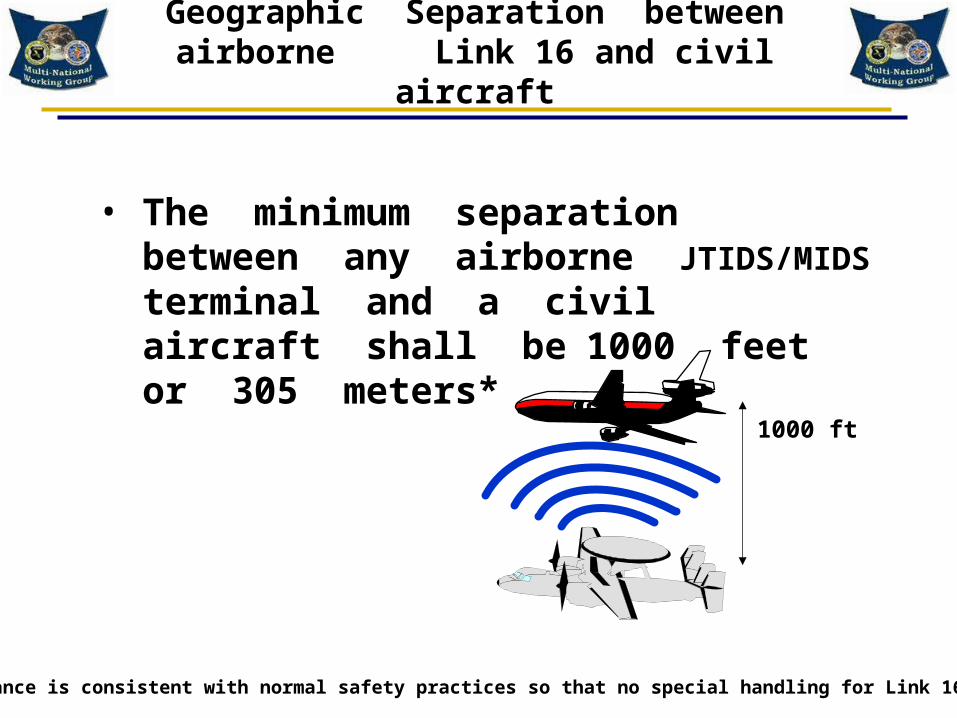
Geographic Separation between airborne Link 16 and civil aircraft
• The minimum separation between any airborne JTIDS/MIDS terminal and a civil aircraft shall be 1000 feet or 305 meters*
* This distance is consistent with normal safety practices so that no special handling for Link 16 is necessary.
1000 ft

Geographic Separation between airborne ATC and Link 16 surface based platforms
• The separation between airborne ATC equipment operating in the 960 to 1215 MHz band and JTIDS / MIDS surface based platforms shall be at least 1000 feet or 305 meters*
* This distance is consistent with normal safety practices so that no special handling for Link 16 is necessary.
Link 16 Ground Site
1000 ft

Interference Protection Features (IPF) Controls
• Interference Protection Features (IPF), also known as EMC Protection Features (EPF) shall be implemented in all Link 16 Terminals or Systems and be fully operational
• Monitors Link 16 transmission characteristics
• Ensures compliance with Spectrum Certification and performance specification requirements

Operating Modes
• Operations shall be in Mode 1 only– Mode 1 is the frequency hopping mode
– Each transmitted pulse contains one of the 51 frequencies
– The transmitted frequency sequence is pseudo random
• The only other operating Mode is Mode 2– All transmitted pulses are on 969 MHz
– Mode 2 is available for testing purposes
US Terminal Remapping Capability
PJCC JTIDS/MIDS Tutorial
May 2012

US Remapping Capability
• Peace time capability – not a requirement
• By 2020 all terminals to have this capability
• Any terminal produced after 2007 will have this capability and are to be fielded no later than 2009
• Terminals produced prior to 2007 will have capability retrofitted when they are brought in for terminal maintenance and/or other scheduled updates.
• Minimum number of frequencies as determined by NTIA
• JTIDS will not require remapping capability
• If it is ever utilized, – Most likely US&P only
– Full 51 frequency operation can be enabled
– Visiting forces can coordinate the use of 51 frequencies
– Additional Link 16 duty factor on remaining authorized carrier frequencies

14JTIDS / MIDSCARRIERS
Frequency Remapping Example
96040CG7
TACAN / DMECHANNELS
EVERY1 MHz
ATCRBSMODE S
IFFTCAS
JTIDS / MIDSFREQUENCIES
EVERY3 MHz
5JTIDS / MIDSCARRIERS
32JTIDS / MIDSCARRIERS
1030 1090
1215960
NewNewAviationAviationSystem(s) ?System(s) ?
Unauthorized Frequencies
969 MHz 1008 MHz
(illustration below shows the case where the lowest 14 frequencies are designated as unauthorized)
The unauthorized carrier will be remapped to an authorized frequency for the pulse The unauthorized carrier will be remapped to an authorized frequency for the pulse
transmission in accordance with a remapping algorithm* calculation performed in each transmission in accordance with a remapping algorithm* calculation performed in each
Terminal. Maintains uniformity on the remaining frequencies. Terminal. Maintains uniformity on the remaining frequencies.
Remapping:Remapping:When an unauthorized carrier frequency gets selected for a MIDS pulse transmission:When an unauthorized carrier frequency gets selected for a MIDS pulse transmission:
* Algorithm defined in the DOD Regulation 4650.1-R1 71

Link 16 EMC Features Monitors
JTIDS/MIDS Tutorial
May 2011

EMC Features
• Required to operate on a “Not to Interfere Basis”• Monitors Link 16 transmission characteristics• Ensures compliance with Spectrum Certification
and performance specification requirements• Originally added to the JTIDS Class 1 Terminal in
1981 after it became operational– Ensure that important aspects of the transmitted waveform
potentially affecting TACAN/DME and MODE S/ SSR equipment compatibility were maintained

EMC Features
• Capability to Transmit Capability to Transmit (CTT) monitor(s)(CTT) monitor(s)
• Uniform use of carrier Uniform use of carrier frequencies functionfrequencies function
• 1030/1090 Low Level 1030/1090 Low Level Detector (LLD)Detector (LLD)
• Pulse width monitorPulse width monitor
• Overpower monitorOverpower monitor
• TSDF limitationsTSDF limitations
• Software controlsSoftware controls– Message structure controlMessage structure control
– Net usage controlNet usage control
– Access mode controlsAccess mode controls
– Relay mode controlsRelay mode controls
– High Power control High Power control
• Full EMC Protection Mode • Exercise EMC Protection Mode• Combat Mode
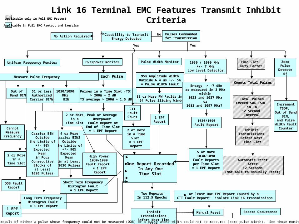
Link 16 Terminal EMC Features Transmit Inhibit Criteria
No
Zero Pulse Detected*
Increment TSDF,
Out of Band BIN,
and Pulse Width Fault
Counter
Pulse Width Monitor
95% Amplitude WidthOutside 6.4 us +/- 5%= Pulse Width Fault
33 or More PW Faults in a 64 Pulse Sliding Window
Overpower Monitor
Measure Each Pulse
5 Pulses in a Time Slot (TS)> 200W + 2 dB
or TS average > 200W + 1.5 dB
Uniform Frequency Monitor
Measure Pulse Frequency
Out of Band BIN
51 or LessAuthorized
Carrier BINs
1030/1090 MHz BIN
CannotMeasure
Frequency
2 or Morein a
Time Slot
2 or Morein a
Time Slot
1 EPFReport
4 or MoreCarrier BINS
Outsidethe Limits of
+/- 90%Expected
Meanin at Least1020 Pulses
Carrier BINOutside
the Limits of+/- 90%
Expected Mean
in FourConsecutive
Blocks ofat Least
1020 Pulses
Long Term Frequency Histogram Fault = 1 EPF Report
High Power 1030/1090
Fault Report = 1 EPFReport
1 EPFReport
Peak or Average Overpower
Fault Report atEnd of Time Slot= 1 EPF Report
One Report RecordedIn Any OneTime Slot
Two ReportsIn 112.5 Epochs
Inhibit TransmissionsBefore Next Time Slot
Manual Reset Record Occurrence
Inhibit Transmissions
Before Next Time Slot
Time Slot Duty Factor
Counts Total Pulses
Total PulsesExceed 50% TSDF
in a12 Second
Interval
Automatic ResetAfter
12 Seconds(Not Able to Manually Reset)
Applicable only in Full EMC Protect
Applicable in Full EMC Protect and Exercise
Pulses Commandedfor Transmission
2 or more in a Time Slot = 1 EPFReport
At least One EPF Report Caused by a CTT Fault Report: isolate Link 16 transmissions
Capability to TransmitEnergy Detected
No Action RequiredNo
YesYes
OOB FaultReport
Short Term Frequency Histogram Fault = 1 EPF Report
CTTFaultCount
1030 / 1090 MHz +/- 7 MHz
Low Level Detector
Energy > -7 dBmas measured in 3 MHz
within 1023 and 1037 MHz
or 1083 and 1097 MHz?
5 or More1030/1090
Fault Reportsper Time Slot
= 1 EPF Report
1030/1090Fault Report
* Note: Zero pulse detected is a result of either a pulse whose frequency could not be measured (OOB) or a pulse whose width could not be measured (zero pulse width). See those monitors. It is not a separate monitor.

QUESTIONS?

Acronyms

ABCCC Airborne Battlefiel Command and Control Center B-AMC Broadband - Aeronautical Multi-Carrier CommunicationABL Airborne Laser BIT Built in TestACAS Airborne Collision Avoidance System BMDO Ballistic Missile Defense OrganizationACC Air Combat Command BRE Beacon Reply EfficiencyACCS Air Command and Control System BW BandwidthACE Allied Command Europe C2 Command and ControlACP Aeronautical Communications Panel of ICAO C2I Command, Control and IntelligenceADA Air Defense Artillery C2P Command and Control ProcessorADatP-33 Allied Data Publications for Link 16 C3 Communications, Command and ControlADCP Air Defense Communications Platform C3I Communications, Command and Control and IntelligenceADF Australian Defense Force C4 Computer, Communications, Command and ControlADS-B Automatic Dependent Surveillance – Broadcast C/A Coarse AcquisitionAEW Airborne Early Warning CAA Civil Aviation Administration or Civil Aviation AgencyAFFMA Air Force Frequency Management Agency CAOC Combined Air Operations CenterAFMO Area Frequency Management Office Cat I Category 1 Precision LandingAGC Automatic Gain Control Cat II Category 2 Precision LandingAIC Air Control Cat III Category 3 Precision LandingAIC Aeronautical Information Circular CCEB Combined Communications Electronics BoardAJ Antijam CCSK Cyclic Code Shift KeyingALTBOC Signal structure for GNSS - Galileo and GPS CE Communications ElectronicsAMACS - All-purpose Multi-channel Aviation Communication System CEPT Conference of European Postal and TelecommunicationsAMF JTRS Airborne Maritime Fixed - Joint Tactical Radio System CFC Common Frequency ClearanceAMF-SA Airborne Maritime Fixed - Small Airborne form factor CG Guided Missile CruiserAM(R)S Aeronautical Mobile (Route) Service CGN Guided Missile Cruiser, NuclearAOC Air Operations Center CJCSI Chairman of the Joint Chiefs of Staff InstructionARB Auxiliary Reference Burst CNPC Control and Non-Payload Communications (for UAS)ARFA Allied Radio Frequency Agency COMSEC Communications SecurityARIES Aircraft Reply and Interference Environment Simulator CPFSK Continuous-phase frequency-shift keying ARINC Aeronautical Radio Incorporated CPG Conference Prepatory GroupARNS Aeronautical Radionavigation Service CPM Conference Prepatory MeetingARSR Air Route Surveillance Radar (Primary Radar) CPSM Continuous-phase Shift Modulation ARTS Automated Radar Tracking System CPSR Conditional Paired Slot RelayASCIET All Service Combat Identification Evaluation Team CP SWG Coordination Procedures Subworking GroupASIT Adaptable Surface Interface Terminal CPU Computer Processing UnitASMGCS Airport Surface Ground Movement Control System CRC Control and Reporting CenterASO Air Staff Office CRE Control Reporting ElementASOC Air Support Operations Center CRYPTO MOD Cryptographic ModificationASOP Acquisition Stable Operating Point CS ( C ) Civilian GPS SignalsATC Air Traffic Control CTT Capability to TransmitATCBI Air Traffic Control Beacon Interrogator CU. FT Cubic feetATCRBS Air Traffic Control Radar Beacon System CV Aircraft CarrierATM Air Traffic Management CVN Aircraft Carrier, NuclearATN Aeronautical Telecommunications Network CW Continuous WaveAWACS Airborne Warning and Control System D DataBADGE Base Air Defense Ground Environment DABS Discrete Access Beacon System

dB Decibel ESC Electronic Systems CenterdBc Decibel relative to the peak carrier power level ESM Electronic Support MeasuresdBi Decibels relative to an isotropic antenna ET Enhanced ThroughputdBm Decibel relative to a milliwatt ETCAS Enhanced Traffic Alert and Collision Avoidance SystemdBm/MHz Decibel relative to a milliwatt in a 1 MHz receiver bandwidth EU European UniondBW Decibel relative to a Watt EUCOM European CommandDC Direct Current EUROCAE European Commission for Civil Aviation EquipmentDDG Guided Missile Destroyer EW Electronic WarfareDFR Data for Record F-3 Tornado Fighter AircraftDFS German Air Navigation Services FA Final ApproachDiv Division FAA Federal Aviation AdministrationDK Denmark FAAD Forward Area Air DefenseDLWG Data Link Working Group FACSFAC Fleet Area Control Surveillance FacilityDME Distance Measuring Equipment FARs Federal Aviation RequirementsDME/N Conventional Distance Measuring Equiment FAS Frequency Assignment SubcommitteeDME/P Precision Distance Measuring Equipment FCA Frequency Clearance AgreementDNA Direction de la Navigation Aérienne FCA EG Frequency Clearance Agreement Experts GroupDOC US Department of Commerce FCC Federal Communications CommissionDOD US Department of Defense FCS Future Communication SystemDOS US Department of State FDD Frequency Division DuplexDOT US Department of Transportation FDL Fighter Data LinkDPG Class 2 Terminal Data Processing Group FDR Frequency Dependent RejectionDx Distance FEC Forward Error CorrectionE-2C Airborne Early Warning Aircraft FIR Flight Information RegionE-3 AWACS FIS-B Flight Information Service - BroadcastE-8 JSTARS FL Forward LinkE3 Electromagnetic Environmental Effects FL Flight LevelE5 Galileo GNSS signal FM Frequency ModulationEC European Commission FMS Foreign Military SalesECAC Electromagnetic Compatibility Analysis Center FMSC Frequency Management SubcommitteeECCM Electronic Counter-Counter Measures FOC Final Operational CapabilityECM Electronic Counter Measures FORSCOM US Forces CommandECP Engineering Change Proposal FP Frequency PanelEF-2000 Eurofighter 2000 FR FranceEF SWG EMC Features Subworking Group FRP Full Rate ProductionEGNOS European Geostationary Navigation Overlay System FRUIT Asynchronous Replies From Non-interrogated aircraftEIRP Effective Isotropic Radiated Power FSD Full Scale DevelopmentEJCC European JTIDS/MIDS Cross-Border Coordination FSK Frequency Shift KeyingEMC Electromagnetic Compatibility FSL Free Space LossEMD Engineering Manufacturing and Development ft FeetEME Electromagnetic Environment FTR FighterEMI Electromagnetic Interference G/A Ground/AirEPE Extraneous Pulse Environment GAAC Geographic Area Assignment CoordinatorEPF Electromagnetic Compatibility Protection Features GAGAN Global Positioning System and GEO Augmentation NavigationEPLRS Enhanced Position Location Reporting System GE GermanyERO European Radiocommunications Office GEO Geostationary satellite

GEOAREA Geographic Area JICO Joint Interface Control OfficerGHz Giga-Herz JICRB Joint International Configuration Review BoardGIOVE Galileo In-orbit Validation Element JM JTIDS Module GLONASS GLObal NAvigation Satellite System JNDA JTIDS Network Design AidGMSK Gaussian minimum shift keying JNDL JTIDS Network Design LibraryGNSS Global Navigation Satellite System JNL JTIDS Network LibraryGPS Global Positioning System JNMS JTIDS Network Management SystemGSM Global System for Mobile Communications JSC Joint Spectrum CenterGt Gain of a Transmitting Antenna JSF Joint Strike Fighter
Gr Gain of a Receiving Antenna JSS JICO Support SystemGTACS Ground Theatre Air Control System JSOW Joint Stand Off WeaponHAVEQUICK Antijam Ultra High Frequency Radio JSPM JTIDS Signal Presence MonitorHDR Header JSTARS Joint Surveillance Target Attack Radar SystemHF High Frequency JTD JTIDS Test DeviceHMU Height Monitoring Unit (type of MLAT) JTRS Joint Tactical Radio SystemHOD Head of Delegation JTIDS Joint Tactical Information Distribution SystemHPA High Power Amplifier JSUG JTIDS Spectrum Users GuideHz Herz (Cycle per second) JTAGS Joint Target Acquisition Ground SystemIA Initial Approach Kbps kilo-bits per secondIADS Icelandic Air Defense System KGV-8 Cryptographic Key GeneratorIBIT Manually Initiated BIT kHz KiloherzICAO International Civil Aviation Organization km Kilometers
ICNIAIntegrated Communications, Navigation, and Identification Avionics KW kilo-watt
ID Identification L1F/L1C Civilian GPS SignalsIF Intermediate Frequency L2 GPS downlink signalIFF Identification Friend or Foe L5 GPS downlink signalIFR Instrument Flight Rulses LAAS Local Air Augmentation SystemIGEB Interagency GPS Executive Board LBS PoundsIJMS Interim JTIDS Message Standard LDACS L-Band Digital Aeronautical Communication SystemILS Instrument Landing System LDL L-Band Digital LinkINE Initial Net Entry LLD Low Level DetectorIOC Initial Operational Capability LM Military GPS Code SignalIPF Interference Protection Features (EMC Protection Features)LOS Line of SightIPO Interntional Program Office LRIP Low Rate Initial ProductionIPPLI Indirect Precise Participant Location and Identification LRU Line Replaceable UnitIPT Integrated Product Team LTH Long Term HistogramIR Investigation Report LVT Low Volume TerminalIRAC Interdepartment Radio Advisory Committee m metersITU International Telecommunications Union MALD Miniture Air Launched DecoyITU-R ITU Radiocommunications Sector Man ManagementJASDF Japan Air Self Defense Force Mbps mega-bits per secondJAF JTIDS Assurance Facility MHz mega hertzJDLMO UK Joint Data Link Management Office MOPS Minimum Operational Performance StandardsJDS JTIDS Deconfliction Server µsec microsecondJFAR JTIDS/MIDS Forecast Activity Report MCE Modular Control EquipmentJFMO Joint Frequency Management Office MIDS Multifunctional Information Distribution System

MIDS JTRSMultifunctional Information Distribution System Joint Tactical Radio System
MIL-STD Military Standard P4SP Packed Four Single PulseMLAT Multi-Lateration System PACAF US Pacific Air ForceMLS Microwave Landing System PACOM US Pacific Command
MNWG Multinational Working Group PFD Power Flux DensityMOA Memorandum of Agreement PFP Partnership for Peace
Mode S ES Mode Select Extended Squitter PJCC Pacific JTIDS/MIDS Coordination Committee of the MNWGMOPS Minimum Operational Performance Standard PPLI Precise Participation Location and Identification
ms millisecond ppps Pulse Pairs Per Second
MSAS Multifunctional Transport Satellite-based Augmentation System Pr Power Received
MSEC Message Security PRF Pulse Repitition FrequencyMSK Minimum Shift Keying PRS(P) Galileo Public Regulated System MTI Moving Target Indicator PSR Primary Surveillance RadarMTL Minimum Triggering Level PTTA Principle Time To Acquire
NASA National Aeronautics and Space Administration P(Y) Precise Positioning Serice with Crypto CapabilityNATO North Atlantic Treaty Organization QNT Quint Networking Technology
NACMA NATO Acquisition Management Agency QZSS Quasi-Zenith Satellite SystemNARFA National Allied Radio Frequency Authority REF Reference
NAS National Airspace System REPROM Repromulgation RelayNATS National Air Traffic Services RES Resolution
NAVAIDS Navigation Aids RF Radio FrequencyNC3A NATO Consultation Command and Control Agency RL Reverse LinkNCTSI Navy Center for Tactical System Interoperability RLOS Radio Line of SiteNDB Non-Directional Beacon RNAV Area NavigationNDF Network Design Facility RNSS Radionavigation Satellite Service
NEXGEN Next Generation ROK Republic of KoreaNFA Notch Filter Assembly RR Radio RegulationNIB Non-Harmful Interference Basis R/SAOC Region/Sector Air Operations Centers
NigComSAT Nigeria Communication Satellite RSBN Radionavigatsionnaya Sistema Blizhney Navigatsii NICP Network Interface Control Program RT Receiver TransmitterNILE NATO Improved Link 11 RTCA Radio Technical Commission for AeronauticsNL Netherlands RTT Round Trip Timing
NM or nm Nautical Mile RTT-A Round Trip Timing - Address ModeNMSC Navy Marine Corps Spectrum Center RTT-B Round Trip Timing - BroadcastNPG Network Participation Group RWR Radar Warning Receiver
ns or nsec nanosecond S SynchronizationNTIA National Telecommunications and Information Administration SARPs Standards and Recommended PracticesNTR Network Time Reference SASWG Spectrum Access Subworking Group of the MNWG
OASD NIIOffice of the Assistant Secretary of Defense for Networks and Information Integration SBAS Satellite Based Augmentation System
OBIT Operational Built in Test SC Special CommitteeOFDM Orthogonal Frequency Division Multiplexing SCWDL Strike Common Weapon Data LinkOOB Out of Band SDB Small Diameter Bomb
OPFAC Operational Facility SDCM GLONASS System of Differential Correction and MonitoringOPTASKLINK Operations Task Link SGV Second Generation VORTAC
P2DP Packed Two Double Pulse Sec Second P2SP Packed Two Single Pulse SES Single European Sky

SICP Subscriber Interface Control Program US&P United States and PossessionsSHAPE Supreme Headquarters Allied Powers Europe USAF United States Air Force
SHORAD Short Range Air Defense USAFE United States Air Force EuropeSLS Side Lobe Suppression us microsecondsSOP Standard Operational Procedures USEUCOM US European Command
SPAWAR Space and Naval Warfare Systems Command USFJ United States Forces JapanSPS Spectrum Planning Subcommittee USMC United States Marine Corps
SPS WG-1 Spectrum Planning Subcommittee Working Group 1 USN United States NavySRU Shop Replaceable Unit UUT Unit Under TestSSR Secondary Surveillance Radar VBW Video Bandwidth
STANAG NATO Standardization Agreement VDL VHF Data LinkSTD Standard Message Format VFR Visual Flight RulesSTH Short Term Histogram VHF Very High FrequencySUA Special Use Airspace VMF Variable Message FormatSV Satellite Vehicle VOR VHF Omni-directional Range
SWP Sweep rate VORTAC VHF Omni-directional Range, TACANSYNC Sychronization VSWR Voltage Standing Wave RatioTACP Tactical Air Control Party WAAS Wide Area Augmentation System
TACAN Tactical Air Navigation WAM Wide Area Multilateration SystemTADIL Tactical Digital Information Link WG Working GroupT&E Test and Evaluation WP Working Party
TAOC Tactical Air Operations Centers WRC World Radio Conference (ITU)TAOM Tactical Air Operations Module WRS Wide Area Reference Station (part of WAAS)TCAS Traffic Alert and Collision Avoidance System WX WeatherTDD Time Division Duplex
TDMA Time Division Multiple AccessTDS Tactical Data System
THAAD Theator High Altitude Area DefenseTIA Telecommunications Industry Association
TIS-B Traffic Information Service - BroadcastTOA Time of Arrival
TP SWG Test Planning Subworking GroupTR Time Refinement
TSDF Time Slot Duty FactorTSEC Transmission SecurityTSO Technical Standard OrderTSR Time Slot ReallocationTTA Time to AcquireUAS Unmanned Aircraft SystemUAT Universal Access TransceiverUHF Ultra High FrequencyUK United KingdomUL Uplink
UMTS Universal Mobile Telephone SystemUS or (U.S.) United States

PJCC National FCA Conditions Starchart
= Meets CFC Condition PC = Platform Centric or radius around every terminal APIS = Radius around Any Point in Space
Country / Platform
AUS BANG CA INDI INDO JA MAL MON NEP NZ PAL PHIL
Function All
TBD All TBD TBD ALL TBD TBD TBD
All but Gnd
Mobile TBD TBD
Low Power (200 Watts) Max TSDF
(100/50)
Standard Messages
(258 Pulses) Packed Messages
(444 Pulses) Individual Nets
(Different Nets Without Time Slot Reuse)
Multinet
(Time Slot Reuse On Different Nets) Contention
(Time Slot Reuse On Same Net) 100 nm
TBD
100 nm
Initial Net Entry /RTT (Modes A & B)
Geo Area Of JTIDS/MIDS Operations
100 nm radius
100 nm 100%
200 nm 400% PC
166 nm radius
100 nm
PC
EMC Features Operational
Records Maintained (One Year)
90 days
Separation (Std ATC V=1000 ft CoAlt H= 3 To 5 nm)
See
Note 2
900 ft from SSR
See note 3
Other Separation
Requirements
0.5 nm from
Beacon
Key:AS = AustraliaBANG = BangledeshCA = CanadaINDI = IndiaINDO = IndonesiaJA = JapanMAL = MalaysiaMON = MongoliaNEP = NepalNZ = New ZealandPAL = PalauPHIL = Philippines

Country / Platform
PNG ROK SING SRI THAI TWN US
Function TBD TBD TBD TBD All All
Low Power (200 Watts) Max TSDF
(100/50) 400
Standard Messages
(258 Pulses) Packed Messages
(444 Pulses) Individual Nets
(Different Nets Without Time Slot Reuse)
Multinet
(Time Slot Reuse On Different Nets) Contention
(Time Slot Reuse On Same Net)
TTTBBBDDD
Limit
Initial Net Entry /RTT
(Modes A & B)
TTTBBBDDD
Geo Area Of JTIDS/MIDS Operations
TTTBBBDDD
100 nm
radius PC
100 nm 100% & 200 nm 400%
PC
EMC Features
Operational
TTTBBBDDD Records Maintained
(One Year)
TTTBBBDDD
Separation (Std ATC V=1000 ft CoAlt H= 3 To 5 nm)
TTTBBBDDD
Other Separation Requirements
Note 4
= Meets CFC Condition PC = Platform Centric or radius around every terminal APIS = Radius around Any Point in Space
PJCC National FCA Conditions Starchart Key:PNG = Papua New GuineaROK = Republic of KoreaSING = SingaporeSRI = Sri LankaTHAI = ThailandTWN = TaiwanUS = United States

Notes
Note 1: Deleted.
Note 2: A Tactical Data System (TDS) airborne terminal shall not radiate when:
1. Within a 1800 ft Disk with a radius of 0.7 nm centered on a civil aviation aircraft2. Within 600 ft altitude and 1.9 nm range of a TACAN / DME ground station3. Within 2900 ft altitude and 3.0 nm range of an SSR ground station4. Within an approach control area.
Note 2: A TDS surface terminal shall not radiate when:
1. Within a 1300/2600 ft (Ground/Ship) vertically and 1.5/1.6 nm (Ground/Ship) horizontally of civil aircraft2. Within 2.0 nm range of a TACAN / DME ground station3. Within 2900 ft altitude and 3.0 nm range of an SSR ground station4. Within 3.6 nm range of an SSR ground station5. Within an approach control area.

NotesNote 3.
1. The minimum separation between any fixed site, marine mobile or ground mobile JTIDS/MIDS terminal and any ground based DME or TACAN beacon used in civil ATC system would be based on a signal level not exceeding -33 dBm at the DME beacon receiver. In instances where testing has not been carried out a distance of 2 NM shall apply. 2. The minimum separation between any fixed site, maritime mobile or ground mobile JTIDS/MIDS terminal and any air traffic control radar beacon system/secondary surveillance radar (ATCRBS/SSR) ground equipment shall be based on a received signal level of -20 dBm (approx 900 ft for 200 watt JTIDS/MIDS terminal). In instances where testing has not been carried out a distance of 2 NM shall apply. 3. The separation distance from a civilian or military aircraft flying under civilian conditions shall be at least standard ATC separation (vertical separation 1000 feet and horizontal separation 3-5 NM). 4. The separation distance between airborne civilian or military aircraft and surface based JTIDS/MIDS platforms shall be at least 1000 ft.
Note 4.1. The TSDF limit for contention (Repromulgation Relay, Time Slot Reallocation (TSR) and machine controlled contention (MCC) is 25 percent of 396,288 pulses in a 12 second frame. MCC includes Round Trip Timing – Broadcast (RTT-B), Precise Participant Location Indicator (PPLI), Initial Net Entry (INE), Fighter to Fighter (Ftr to Ftr) and Conditional Paired Slot Relay (CPSR). If only fast moving platforms use MCC then the contention limit is 33 percent. 2. Surface based JTIDS/MIDS terminals must be located at distances that protect Tactical Air Navigation (TACAN) and Distance Measuring Equipment (DME) beacons from JTIDS/MIDS signals that exceed a power level of -33 dBm and a combined maximum 50% TSDF at the beacon receiver input. In the event that this received signal condition cannot be met, then up to a peak power level of -24 dBm and a combined maximum 20% TSDF at the beacon input may be permitted, however this latter condition must be identified to th eNTIA by the Navy Marine Corps Spectrum Center (NMSC) prior to authorization and use. For any and all power levels between -24 dBm and -33 dBm, coordination and authorization from NMSC is required.3. Surfaced –based JTIDS/MIDS terminals will be located at distances that protect ATCRBS Interrogators and Mode S Sensors from signals that exceed a peak power level of -20 dBm at their respective receiver input.4. There is also a 400% TSDF limit within a 200 NM radius of all terminals.


![[PPT]ALOHA FROM HAWAIIekladata.com/T87xXLe0Y72JoKgvTgg575PI2tM/Hawaiil.pps · Web view* HONOLULU - HARBOUR HONOLULU - AIRPORT HONOLULU IOLANI PALACE - HONOLULU ROYAL GUARD KAMEHAMEHA](https://img.pdfslide.net/doc/110x75/5af655b67f8b9a5b1e8effcd/pptaloha-from-view-honolulu-harbour-honolulu-airport-honolulu-iolani-palace.jpg)