Embed Size (px)
Citation preview
1 A.06228
PK-232/DSP MULTI-MODE CONTROLLER OPERATION
Welcome to the world of Digital Signal Processing. You may be acquainted with DSP in your new radio,or you may have a Timewave Technology DSP unit in your shack. Now you have DSP capability foryour PK-232 digital modes. Here are the most frequently Asked Questions (FAQ’s) we have been get-ting.
What exactly have I bought? The DSP board you have installed provides a proven set of DSP BrickWall data filters to your PK-232MBX. These are:
45 Baud Baudot Twin Peak filter for RTTY100/200 CW filters (Jumper selected, Shipped with jumper on, set at 200)100/200 Adaptive PACTOR filters100 Baud AMTOR/NAVTEXT300 Baud HF Packet1200 Baud UHF/VHF PacketEuropean/American Tone Set (Jumper selected, Shipped with jumper off, American Tones)WEFAXSIAM
Can I use my existing software? In a word, YES. The new firmware provides all the control necessaryto select the proper filter, even switching between 100 and 200 baud PacTOR filters as the PK-232/DSPchanges the baud rate to accommodate changes in the transmission path.
What should I expect from the new board? DSP provides sharper skirts that reduce the noise in theband pass as well as rejecting interference from adjacent signals. In RTTY this can improve error ratesup to 100 times in weak signal and noisy environments. Tune slowly, signals will appear to just pop outof the noise. We suggest you start with a fairly wide filter setting in your radio and cascade that with thenarrower filter of the Multi-Mode Controller.
What else has changed? The small red LED on the board will light when a signal overloads the DSPinput (Note that a remote light can be tied to Jumper next to the overload LED). The startup sequence isalso new, notice that an extra set of lights blink during startup. This tells you the version 7.2 firmware isinstalled.
Timewave TechnologyVisit our web page: http://www.timewave.com to download a demo copy of our PK-Term’99 program.
Timewave Technology Inc.501 W. Lawson Ave.St. Paul, MN 55117-4771 USA
651-489-5080FAX [email protected]
2 A.06228
PLEASE READ THIS BEFORE INSTALLATION
INSTALLATION INSTRUCTIONS ADDENDUM
Before you start the installation on your PK-232MBX upgrade, please inspect the daugh-ter-board. There are 2 28-pin double headers that plug the daughter-board into the PK-232 main circuit board. Take a minute and inspect this header and make sure the pins arenot bent or badly aligned.
When you reach the point in the installation instructions asking you to “place the Pakmaildaughter-board over the standoffs” make very certain that the pins of both headers alignexactly over the main board sockets of U-2 and U-4.
After installing the Pakmail-board double check the alignment. Make certain the first rowof the header pins is in the first row of IC socket holes, not one row behind.
Replacement headers are $6.00 each, plus shipping and handling.
73
Service DepartmentTimewave TechnologyVisit our web page: http://www.timewave.com
3 A.06228
INSTALLATION INSTRUCTIONSPK-232 PAKMAIL BOARD
With LITHIUM BATTERYThank you for purchasing the PakMail Upgrade for your PK-232/HK-232. The following instructionsare to assist you with the installation on the PakMail daughter-board and the lithium battery. Please readthese instructions completely before beginning this project.
PARTS LIST AND TOOLS
Your upgrade kit should contain, the following parts:
QTY PART DESCRIPTION
1 PakMail daughter-board1 Lithium Battery1 PK-232MBX Manual2 Stand-offs, male by female threads, 6-32 x ½1 Warranty Card
You will need the following tools to perform this installation:
#2 Phillips screwdriverSmall flat-blade screwdriverPencil type soldering ironPortable desoldering tool (solder remover)1/4’inch nut driver - OR – 1/4 inch wrenchSmall wire cuttersSmall needle-nose pliers
PAKMAIL DAUGHTER-BOARD
Prepare a clean work area that is as static-free as possible.
-NOTICE-Be sure to discharge any static build-up you may have incurred by touching a grounded appli-ance before proceeding.
Remove the PK-232 top cover by removing the six screws. Remove any AA batteries that may beinstalled in the top cover battery holder. Remove the three-cell battery holder by grasping firmly andtwisting the battery holder off (if the battery holder is held by adhesive, some early PK-232’s had batteryholders screwed to the top cover). Cut the battery leads about six inches above the printed circuit board.Grasp each wire with the needle nose pliers and heat the solder connections on the board. When thesolder has been heated, pull the wires out.
4 A.06228
Using the soldering pencil and the desoldering tool, remove the old solder from the points where the battery wireswere attached to the printed circuit board.
CAUTION: DO NOT TRY TO PRY THE SOCKET OFF THE BOARD. Be sure that you are workingwith the EPROM itself.
Using the small flat blade screwdriver, remove the following, socketed IC’s from the PK-232 and set aside. Keepthese parts in a safe place.
EPROM U-2 At this time, make a mental note as to theEPROM U-3* location of the now empty sockets U-2 and U-4.RAM U-4*RAM U-5Note: To install in older PK-232 and Heathkit HK-232 units, move jumper JP7 to JP8.* These Parts may NOT be in your PK-232.
With the front panel of the PK-232 facing you, remove the two screws that hold the PK-232 printedcircuit board to the bottom chassis that are located in the left rear and left front part of the board. Screwthe male threads of each of the stand-offs in place of the two screws just removed. Now place thePakMail daughter-board along the left side of the PK-232, with the notch on the daughter-board towardsthe front.
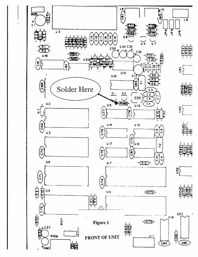
Locate resistor R-186 on the PK-232 mother board Fig. 1. Solder the wire from the PakMail daughter-board to the LEFT side of resistor R-186 on the PK-232 mother-board. See Fig. 1.
Make sure that sockets U2, U3, U4 and U5 on the PK-232 motherboard are empty. Now place thePakMail daughter-board over the stand-offs. The two 28-pin plugs on the bottom of the PakMail boardwill be inserted into the now empty sockets U-2 and U-4. Line up all of the pins before pressing thedaughter-board into place.
Attach the PakMail daughter-board to the stand-offs with the two screws you removed from the PK-232motherboard earlier. This completes the installation of the PakMail daughter-board.
LITHIUM BATTERY
NOTE:Some PK-232’s may already have a lithium battery installed. If yours is one of these, disregard theseinstructions.
Locate the lithium battery. Observe that one side of this battery is labeled as the POSITIVE side.
- WARNING -Do NOT short the leads of a lithium battery.Do NOT dispose of in a fire.Do NOT reverse polarity when installing a lithium battery.
5 A.06228
Applying heat directly to the lithium battery or installing the battery backwards can cause damage toyou and the PK-232. Use extreme caution. Timewave Technology Inc. will not be liable for any damagecaused by improper installation.
Overheating the battery or reversing the polarity may cause damage to you or your PK-232. Please usecare when installing the battery. Make sure that the battery has been installed properly. Be sure to use apencil type soldering iron when installing the lithium battery. Please use extreme caution.
Cut the lead length of the lithium battery to 1/4 inch. Failure to trim the battery lead length may result ina short between the two battery terminals against the PK-232 bottom panel. See warning above.
Install the lithium battery in the two holes where the battery wires were. Of the two holes on the printedcircuit board, the hole closest to jumper JP-l is the positive battery terminal. This battery may be sol-dered in from the component side of the board. Jumper JP-1 is used to isolate the battery from thecircuit. If the jumper is covering both pins, then the battery IS in the circuit, and hence the PK-232MBXparameters will be stored in the PK-232 when power is removed. To take the battery out of the circuit,remove the jumper and replace on only one of the two pins.
Should jumper JP-1 be left on or off?
If you are going to be using the program PC-PakRatt for Windows or PK-Term’99, it is best to leavethe battery out of circuit (Jumper JP-1 off). For all other applications, (COM-PakRatt, MacRatt ordumb terminal) leave the battery in circuit (Jumper JP-1 on).
This completes the installation of the lithium battery.
RE-ASSEMBLY
Replace the PK-232 top cover with the six screws.
6 A.06228
PLEASE READ THIS BEFOREDSP BOARD INSTALLATION
INSTALLATION INSTRUCTIONS ADDENDUM
Before you start the installation on your PK-232/DSP upgrade, please inspect the DSPdaughter-board. There is a 40-pin double header that plugs the daughter-board onto thePK-232 main circuit board. Take a minute and inspect this header and make sure the pinsare not bent or badly aligned.
When you reach the point in the installation instructions asking you to “place the DSPdaughter-board over the standoff” make very certain that the pins of the header arealigned exactly over the main board socket U-6.
After installing the DSP-board, double check the alignment of the daughter-board andsocket on the main board. Make certain the first row of the header pins is in the first rowof IC socket holes, not one row behind.
Replacement headers are $8.00 each, plus shipping and handling.
73
Service DepartmentTimewave TechnologyVisit our web page: http://www.timewave.com
7 A.06228
READ CAREFULLY BEFORE STARTING INSTALLATION
INSTALLATION INSTRUCTIONSPK-232/DSP BOARD
Thank you for purchasing the DSP upgrade for your PK-232MBX. The following instructions are toassist you with the installation of the DSP daughter-board. Please read these instructions completelybefore beginning this project.
PARTS LIST AND TOOLS
QTY PART DESCRIPTION
1 DSP daughter-board (A.06225) 1 Standoff
You will need the following tools to perform this Installation.
#2 Phillips screwdriverSmall flat blade screwdriverNeedle nose pliers Small wire cutters or nippers1/4" nut driverSolder iron or pencil (Do not use a solder gun)Solder
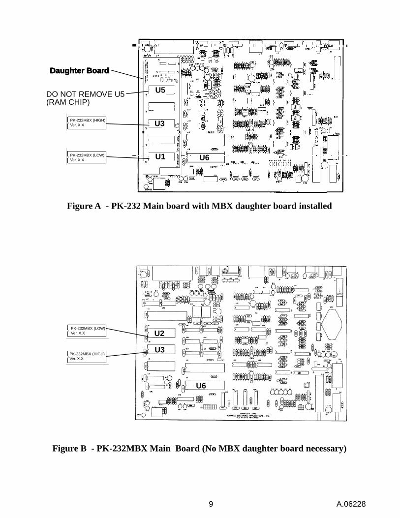
Please take a minute and make certain that the PK-232 you are upgrading is a PK-232MBX. If the unityou have was built as a PK-232MBX (Fig. B) skip to the next paragraph. If you are upgrading a PK-232or PK-232 that has been upgraded to an MBX with an older wide board (Fig. A) you should replace thatboard with the narrow board supplied with this kit. The newer style narrow board is identified by the partnumber A.06239A. After installing the MBX upgrade, test the unit briefly before proceeding with theDSP upgrade.
Prepare a clean work area that is as static free as possible.
IMPORTANT NOTICE
Be sure to discharge any static build-up you may have incurred by touching a grounded appliance beforeproceeding.
1) Remove all cables and power from the PK-232.
2) Remove the top cover by removing the 6 screws from the side and back of the unit. Position the unitwith the front toward you.
3) Determine if you have an old or new style board. Old boards have four 28 pin IC sockets runningdown the left side of the motherboard. New boards have three 28 pin IC sockets running down the
8 A.06228
left side of the board (see figure B).
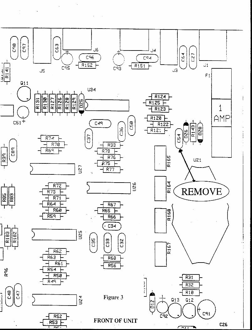
4) Locate and remove C-54 (located to the left of the fuse) using the wire cutters or nippers. (see fig. 3)
5) Using the flat blade of the screwdriver, carefully remove U6 from its socket and set aside. (Note howthe chip is oriented in the socket, notch to the left as viewed from the front).
CAUTION: DO NOT TRY TO PRY THE SOCKET OFF THE BOARD. Be sure that you areworking with the EPROM itself.
6) Using the Phillips screwdriver, remove the front center screw from the board and set the screw aside.
7) Install the standoff into the hole in the front where you just remove the screw. Secure the standoffwith the 1/4" nut driver. DO NOT OVER TIGHTEN . This may damage the board or break the standoff.
8) Place the DSP board (part number A.063225) over the U6 socket. Be sure all 40 pins of the DSPboard are aligned with the 40 holes of the socket U6. Press down firmly to seat the DSP board. Recheckthe alignment of the pins into the socket.
9) Secure the DSP board with the screw set aside in step 5. DO NOT OVER TIGHTEN.
10) With the notch to the left, place U6 (removed in step 5) in the socket on the DSP board and Afterchecking U6 to make sure all the pins are correctly aligned, press the chip firmly down. Check carefullythat all pins are in the socket and not folded nor bent).
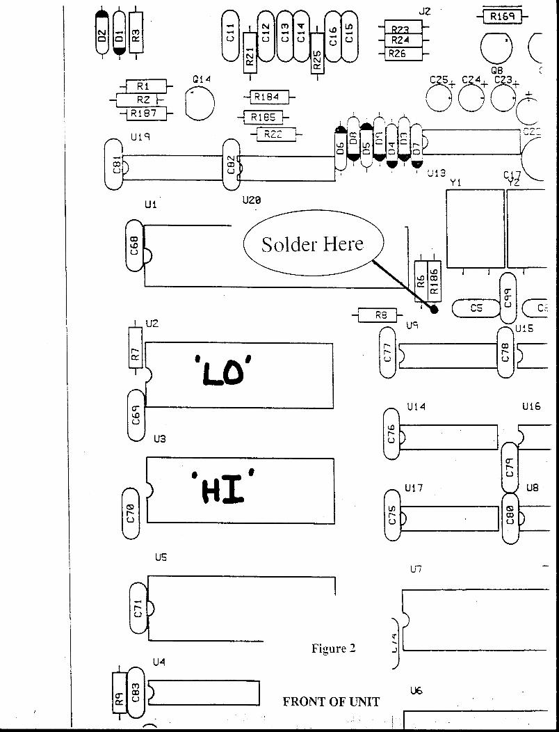
11) Starting with the left side wire on the DSP board. Attach this wire to R-186 (330 ohms Orange,Orange, Brown). Bend the wire in a “U” around lead of R-186, then press the ends of the “U” togetherusing the needle nose pliers. If your PK-232 board is an “old” style board attach the wire to the left sideof R-186 see fig 1. If your board is a “new” style board attaches the wire to the bottom (Toward thefront) of R-186. Solder the connection. See fig. 2
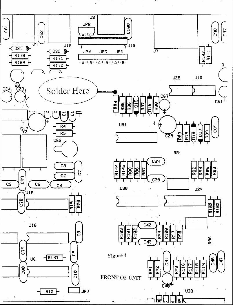
12) The center wire is attached to the top lead of R-34 (10K ohms, Brown, Black, Orange) see fig. 4.Use the same “U” bend technique to attach the wire that you used on R-186. Solder.
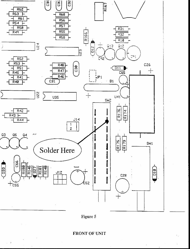
13) T he right side wire is attached to the second pin from the top on the right side of the radio switch(SW2). Again make the “U” bend and attach the wire to the pin, then press the “U” together to make astrong mechanical attachment, Finish by soldering the connection. See fig 5. If the switch in yor PK-232does not have external lugs the wire can be attached to the back pad of C-54 (C-54 was removed in step4)
14) Replace the top cover and install the six screws removed in step 2.
9 A.06228
U5
U3
U1
Daughter BoarDaughter BoarDaughter BoarDaughter BoarDaughter Boar ddddd
DO NOT REMOVE U5(RAM CHIP)
PK-232MBX (HIGH)Ver. X.X
PK-232MBX (LOW)Ver. X.X
Figure A - PK-232 Main board with MBX daughter board installed
Figure B - PK-232MBX Main Board (No MBX daughter board necessary)
PK-232MBX (LOW)Ver. X.X
PK-232MBX (HIGH)Ver. X.X
U2
U3
U6
U6
1 1
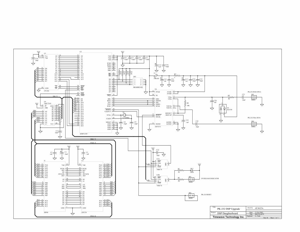
PK-232 DSP Upgrade AP.06225a
11-Oct-2002
Title:
Size:
TW P/N:
Date:File:
Sheet ofBEngineer:
Project:
Timewave Technology Inc. A. ClarkDSP Daughterboard
PCLK16
IEO18
IEI17
/INT24
A135 A034
/RD5
/INTACK25
/WR6
/CE36
D74 D63 D52 D41 D340 D239 D138 D037
GND7
Vdd23 PA0 33
PA1 32
PA2 31
PA3 30
PA4 29
PA5 28
PA6 27
PA7 26
PB0 8
PB1 9
PB2 10
PB3 11
PB4 12
PB5 13
PB6 14
PB7 15
PC0 19
PC1 20
PC2 21
PC3 22
U1
Z85C36
A932
A1033
A1134
A1235
A1336
A730 A628 A527 A425 A324 A223 A122 A021
BR 18
A831
D178
D189
D1911
D2012
D2113
D2214
D2315
D167
DMS38 PMS37
Vdd 16
BG 40
BMS39
D7 65
D967
D1068
D111
D123
D134
D145
D156
D866
MMAP 17
IRQ2 19
D1 59
D3 61D2 60
D0 58
D6 64D5 63D4 62
CLKIN 42
XTAL 41
CLKOUT 43
DT1 52
TFS1 53
SCK1 56
RFS1 54
Vdd 57
GND 2
GND 10
GND 29
GND 49
Vdd 26
RD45
WR44
DR1 55
DT0 46TFS0 47
SCK0 51
RFS0 48
DR0 50
RESET 20
U2
ADSP-2105
A0 10
A1 9
A2 8
A3 7
A4 6
A5 5
A6 4
A7 3
A8 25
A9 24
A10 21
A11 23
A12 2
A13 26
A14 27
CE 20
OE 22
D011
D112
D213
D315
D416
D517
D618
D719
Vcc28
GND14
Vpp1
U3
27C256
PRE10
CLK11
D12
CLR13
Q 9
Q 8
U5B
74HC74
PRE4
CLK3
D2
CLR1
Q 5
Q 6
U5A
74HC74
G19
DIR1
A02
B0 18
A13
B1 17
A24
B2 16
A35
B3 15
A46
B4 14
A57
B5 13
A68
B6 12
A79
B7 11
VCC 20
GND 10
U474HCT245
Y1
8.192MHz
PCLK 16
IEO 18
IEI 17
/INT 24
A1 35A0 34
/RD 5
/INTACK 25
/WR 6
/CE 36
D7 4D6 3D5 2D4 1D3 40D2 39D1 38D0 37
GND 7
Vdd 23PA033
PA132
PA231
PA330
PA429
PA528
PA627
PA726
PB08
PB19
PB210
PB311
PB412
PB513
PB614
PB715
PC019
PC120
PC221
PC322
J1
DIP40
VCC
C110uF
C2.1uF
C3.1uF
VCC
PA0PA1PA2PA3PA4PA5PA6PA7
PB0PB1PB2PB3PB4PB5PB6PB7
PC0PC1PC2PC3
PA0PA1PA2PA3PA4PA5PA6PA7
PB0PB1PB2PB3PB4PB5PB6PB7
PC0PC1PC2PC3
PC[0..3]
PA[0..7]
PB[0..7]
VCC
C1010nF
D[0..7]
D0D1D2D3D4D5D6D7
D0D1D2D3D4D5D6D7
D0D1D2D3D4D5D6D7
VCC
PB4PB5PB6PB7
PA0PA2PA5
C410nF
C510nF
C610nF
C710nF
VCC
C822pF
C922pF
C1410nF
C131uF
R7
2
L1
FBEAD C151uF
C1610nF
C1810nF
C171uf
VCC
D0
D1R6
1K
R5
1K
JH1
HDR2
DL1
RED
VCC
JH2
HDR2
R9
1K
C22
10nF
JH4
HDR2
13 2
D1BAV99
C201nF
JH3
HDR2
C21
10nF
PK-232 RXD (SW2)
PK-232 Filter (R34)
OVERLOAD INDICATOR
PK-232 RESET
C12
10nF
C1110nF
S06225a.SCH
1 23 45 67 8
JH5
HEADER 4X2
R11K
R21K
R31K
R41K
C23.1uF
VINp 5
SDOFS17
SDI19
SDIFS18
SCLK14
SDO16
VOUTp 1
VINn 6
VOUTn 2
DGND11 AGND2 10AGND1 4
DVdd12 AVdd1 3
REFOUT 7
RESET13
MCLK15
SE20 AVdd2 9
REFCAP 8
U6
AD73311
C1910nF
R810K
VCC