Embed Size (px)
Citation preview

Touch it !
TSL – Trust Your Senses to a Proven Par tner
CUSTOMIZE YOUR OWN BUTTON
Door Opening Buttons PK52 Series
PK52 SERIES
EN
2
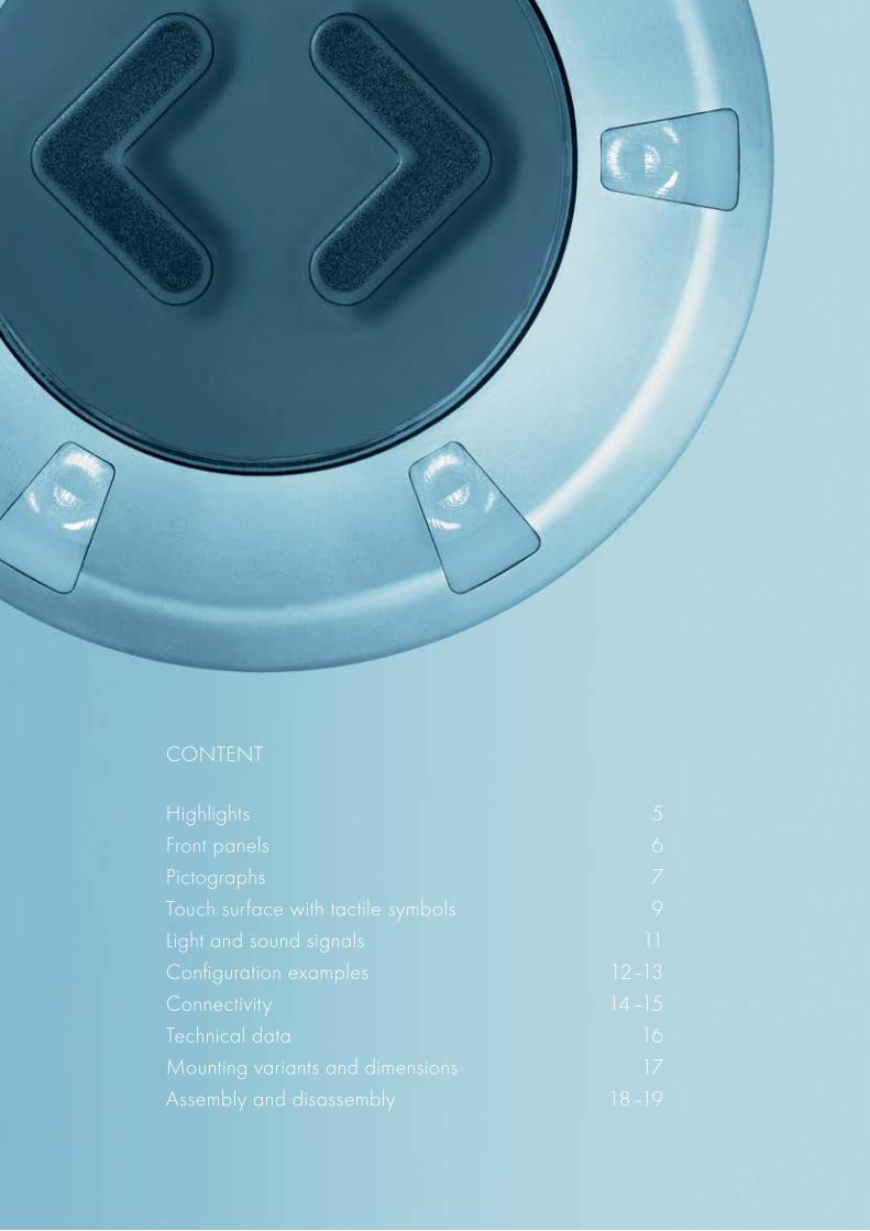
CONTENT
Highlights 5
Front panels 6
Pictographs 7
Touch surface with tactile symbols 9
Light and sound signals 11
Configuration examples 12–13
Connectivity 14–15
Technical data 16
Mounting variants and dimensions 17
Assembly and disassembly 18–19

3
THE NEW GENERATIONOF DOOR OPENING BUTTONS
PK52 SERIES
Within the Presskey family, the PK52 series offers several new product features.During the development phase, two important priorities were taken into account.
USER-FRIENDLY BUTTONS
The operational characteristics have been improved compared to conventional buttonsin the field. The engineers of TSL-ESCHA focused the design on passengers with specialneeds. Extremely large touch surface, excellent lateral visibility of signal lights, and tactilefeedback while pressing are only a few examples that ease the detection of the door opening button and make simpler its operation.
SIMPLIFIED LOGISTICS
During the development, TSL-ESCHA closely looked over the requirements of door manufacturers. The result is an intelligent customized button with integrated controller functions. The PK52 buttons meet the special require-ments of train operators as their light and audible signals offer superior performance. Many different functions are possible now in only one product.
4

5
HIGHLIGHTS
HIGHLIGHTS AT A GLANCE
Large ActiveTouch Surface
Additional Options
ParameterizableLight Signals
ParameterizableAudible Signals
Invisible MountingComponents
IntegratedMicro Controller
Flat Design
Extended Voltage Range24 –110 VDC
Excellent Lateral Visibilityof Signal Lights
TactileFeedback
Protection Level IP67
Raised Symbols in Accordancewith TSI PRM & ADA Standards
Backlit TouchSurface
IsolatedOutput
Graffiti RemoverResistant Coating

6
CONFIGURATION
FRONT PANELS
High quality stainless steel panels in different RAL- colors
TRAFFIC YELLOWsimilar to RAL 1023
TRAFFIC BLUEsimilar to RAL 5017
TRAFFIC GREENsimilar to RAL 6024
TRAFFIC GRAY Asimilar to RAL 7042
TRAFFIC WHITEsimilar to RAL 9016
STAINLESS STEEL MATTE SHOT-BLASTED(uncoated)
TRAFFIC REDsimilar to RAL 3020
NIGHT BLUEsimilar to RAL 5022
LIGHT GRAYsimilar to RAL 7035
TRAFFIC GRAY Bsimilar to RAL 7043
TRAFFIC BLACKsimilar to RAL 9017
CUSTOM COLORS(Upon request with an additional cost fee and minimum order of 100pc.)
Configuration Status “Front Panels”
RAL colors are only for reference. Slight color deviations are inevitable in the manufacturing process.
7
STRAIGHTFORWARD
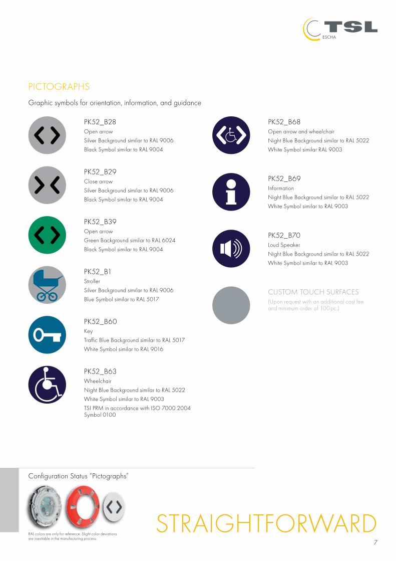
PICTOGRAPHS
Graphic symbols for orientation, information, and guidance
PK52_B28Open arrow
Silver Background similar to RAL 9006
Black Symbol similar to RAL 9004
Configuration Status “Pictographs”
RAL colors are only for reference. Slight color deviations are inevitable in the manufacturing process.
PK52_B29Close arrow
Silver Background similar to RAL 9006
Black Symbol similar to RAL 9004
PK52_B39Open arrow
Green Background similar to RAL 6024
Black Symbol similar to RAL 9004
PK52_B1Stroller
Silver Background similar to RAL 9006
Blue Symbol similar to RAL 5017
PK52_B63Wheelchair
Night Blue Background similar to RAL 5022
White Symbol similar to RAL 9003
TSI PRM in accordance with ISO 7000 2004 Symbol 0100
PK52_B60Key
Traffic Blue Background similar to RAL 5017
White Symbol similar to RAL 9016
PK52_B68Open arrow and wheelchair
Night Blue Background similar to RAL 5022
White Symbol similar RAL 9003
PK52_B69Information
Night Blue Background similar to RAL 5022
White Symbol similar to RAL 9003
PK52_B70Loud Speaker
Night Blue Background similar to RAL 5022
White Symbol similar to RAL 9003
CUSTOM TOUCH SURFACES(Upon request with an additional cost fee and minimum order of 100pc.)

8

9
CONFIGURATION
Configuration Status “Tactile Symbols”
TOUCH SURFACE WITH TACTILE SYMBOLS
Due to the modular design of the PK52 buttons, pictographs and tactile touch surfaces can be combined. Tactile symbols are subtly raised. Designs and sizes are in full compliance with TSI PRM & ADA standards.
T0Standard Surface without Tactile Symbol
T1Open Arrow
T2Close Arrow
T3Key
T4Information
T5Loud Speaker
T6Open and Close Arrow
CUSTOM TOUCH SURFACES(Upon request with an additional cost fee and minimum order of 100pc.)
FEEL THE INFORMATION

10
CONFIGURATION
FULLY CUSTOMIZABLE FUNCTIONS OF THE PK52
The following chapter describes the fully customizable functions of the PK52. These are combinations of personalized light signals, audible signals, and additional control functions. Customers can define preferred signal types. TSL-ESCHA downloads these programs into the PK52.
ADDITIONAL INPUTS AND OUTPUTSPK52 offers the option to trigger programs by an external control unit (e.g. door control unit) with two inputs (In1 and In2). The function of the output (Out) is also parameterizable (e.g. timer functions).
INTEGRATED MICRO CONTROLLERThe PK52 has an integrated micro controller. Perso- nalized light and audible signals can be downloaded into this controller.

11
LIGHT SIGNALS OF THE PK52
L0
L1
L2
L6
L7
Customize your LED combination
L3
L4
L5
SOUND SIGNALS OF THE PK52
A0 A1 A2 A3 A4 A5Frequency: – 3.5 kHz 3.8 kHz 2.1 kHz / 3.5 kHz 480 Hz 1.9 kHz
Duration: – 0.5 sec. 0.05 sec. 2 ms 50 ms
Interval: – 1-time 0.5 Hz 2 Hz 280 ms 100 ms
Function: – Confirmation Orientation Release “Toc”signal Door Closing
SEE AND HEAR THE BUTTON
Configuration Status “Light Signals”
Light signal parameters of the PK52 are fully customizable. A selection of standard variants is shown in the following chart. Furthermore TSL-ESCHA offers personalized light signals.
Audible signal parameters of the PK52 are fully customizable. A selection of standard variants is shown on the following chart. Furthermore TSL-ESCHA offers personalized audible signals.

12
CONFIGURATION
CONFIGURATION EXAMPLES
In previous pages, examples of personalized light and sound signals were illustrated. The different light and audible signals of the PK52 button are generated depending on its operation mode.The PK52 has two additional inputs (In1 and In2) in order to adjust to different operation modes of the vehicle or the doors. For example, the button control can enable an out-of-order door to be indicated or during a night ride the sound level to be reduced. The configuration options are as varied as the requirements of different applications. The combination of light, audio, and input signals (In1 and In2) as well as the desired function of the output (Out) can be achieved without the development of new electronics. New parameters can simply be programmed into the integrated microcontroller. In this way also special button functions can be personalized fast and inexpensively.
Even requests of changes, which sometimes come up after the approval phase of the vehicle, are considerably easy and inexpensive.
The following charts exemplify the diverse options of the PK52. Each table represents one personalized button and describes the light and audible signals of each single operation state.
PROGRAM: N1
INPUT ENABLE ACTIVATED FUNCTION
IN 1 IN 2 LED TONE OUT LED TONE OUT
nc nc L1 A2 – L4 A1 on · Enable Green· Activated Red· Orientation and Confirmation Tone· Inputs Unused· Number of Wires: 3
nc nc L1 A2 – L4 A1 on
nc nc L1 A2 – L4 A1 on
nc nc L1 A2 – L4 A1 on
PROGRAM: N2
INPUT ENABLE ACTIVATED FUNCTION
IN 1 IN 2 LED TONE OUT LED TONE OUT
nc 0 L0 A0 – L0 A0 on · Ready Green· Activated Red· Orientation and Confirmation Tone· In2: Enabling· Number of Wires: 4
nc 0 L0 A0 – L0 A0 on
nc 1 L1 A2 – L4 A1 on
nc 1 L1 A2 – L4 A1 on

13
Configuration Status “Parameterizable Functions”
NOTE: Every personalized function determines the number of wires in the connection cable as well as the pin assignment of the connector -> see page 14/15 “Connectors”.
PROGRAM: N3
INPUT ENABLE ACTIVATED FUNCTION
IN 1 IN 2 LED TONE OUT LED TONE OUT
0 0 L0 A0 – L5 A0 on · Enable Green· Activated Red· Orientation, Confirmation, Door Closing, and Out-of-Order Door Tone· In1: Enabling, In2: Door Closing and Out-of-Order Door· Number of Wires: 5
1 0 L1 A3 – L4 A1 on
0 1 L6 A5 – L6 A5 on
1 1 L5 A0 – L5 A0 on
PROGRAM: N4
INPUT ENABLE ACTIVATED FUNCTION
IN 1 IN 2 LED TONE OUT LED TONE OUT
0 0 L0 A0 – L0 A0 on · Enable Green· Activated Red· In1: Enabling, In2: Muted Tones· Number of Wires: 5
1 0 L3 A2 – L5 A1 on
0 1 L0 A0 – L0 A0 on
1 1 L3 A0 – L5 A0 on
CREATE YOUR PERSONALIZED CONFI GURATION:
INPUT ENABLE ACTIVATED FUNCTION
IN 1 IN 2 LED TONE OUT LED TONE OUT
0 0
1 0
0 1
1 1

14
CONNECTIVITY
PIN 1 2 3 4 5 6 Appearance
Color Brown White Blue Black Grey n. c.
Signal +UB In 1 Gnd (0V) Out In 2 –
Number of poles 6
Type of connector Rectangular connector, MATE-N-LOK®
Cable Radox TENUIS, TW / S5F® 4x0.5 mm
Description TYCO Electronics / AMP, 794895-1
Protecion level IP67
Cable length 10 cm
PIN ASSIGNMENT FOR CONNECTOR 65
Cable sealing
1
4
2
5
3
6
Cable sealing
1
3
2
5
31
4
2
1
4
32
4
62
4
1
3 5
Cable sealing
1
4
2
5
3
6
Cable sealing
1
3
2
5
31
4
2
1
4
32
4
62
4
1
3 5
PIN 1 2 3 4 Appearance
Color Brown White Blue Black
Signal +UB In 1 Gnd (0V) Out
Number of poles 4
Type of connector Rectangular connector, MATE-N-LOK®
Cable Radox TENUIS, TW / S4F® 4x0.5 mm
Description TYCO Electronics / AMP, 794805-1 corresponding BN65074
Protecion level IP67
Cable length 10 cm
PIN ASSIGNMENT FOR CONNECTOR 64
Warning: varieties with 5 and 6 poles are only for an operating voltage of 60V or less.
Kabelabdichtung
1
4
2
5
3
6
Kabelabdichtung
1
3
2
5
31
4
2
1
4
32
4
62
4
1
3 5
PIN 1 2 3 4 5 6 Appearance
Color Brown White Blue Black Gray Red
Signal +UB In 1 Gnd (0V) Out In 2 In 3
Number of poles 5–6
Type of connector Connector, M12x1
Cable Radox TENUIS, TW / S...F® 4x0.5 mm
Description ESCHA M12x1, 4-, 5-, 6-polig WAS4...WAS6
Protecion level IP67
Cable length 50 cm
PIN ASSIGNMENT FOR CONNECTOR 61

15
DIAGRAM PNP
+UB
In 1
In 2Out
Sounderoptional
Gnd (0V)
rd gn
Mic
ro-
Con
trol
ler
Configuration Status “Connectors”
Kabelabdichtung
1
4
2
5
3
6
Kabelabdichtung
1
3
2
5
31
4
2
1
4
32
4
62
4
1
3 5
Warning: only for an operating voltage of 60V or less.
PIN 1 2 3 4 Appearance
Color Brown White Blue Black
Signal +UB In 1 Gnd (0V) Out
Number of poles 4
Type of connector Connector, M8X1 with snap-on interlock
Cable Radox TENUIS, TW / S4F corresponding BN65074
Description ESCHA Durchmesser 8mm M8x1 (SSFP4), 4-poles, SSP4
Protecion level IP67
Cable length 10 cm
PIN ASSIGNMENT FOR CONNECTOR 60

16
TECHNICAL DATA
Electrical Data Mechanical Data Environmental conditions
Nominal voltage 24 VDC - 110 VDC Housing and button surface
UV-Stabilized Polycarbonate (UL94 V-0)
Operating life Approx. 7,000,000 switching cycles
Operating voltage 16.8–143 VDC Front panel Stainless Steel, optional matte shot-blasted or powder coated
Operating temperature -40°C to +80°C
Nominal current Max. 200 mA Push button diameter 87 mm diameter of the touch surface 52mm
Protection level Waterproof front IP67, rear IP64
Operating current Approx. 10 mA Operating force Approx. 8N and switch travel of approx 0.8mm tactile switching
Connection 6 LEDs (wiring options in Light Signal section)
Optional connections Connectors section
Switching output P-switching output Electronics protected against humidity
TECHNICAL DATA

17
DRAWINGS AND DIMENSIONS
MOUNTING VARIANTS AND DIMENSIONS
FRONT VIEW SIDE VIEW
DRILL PATTERN “A” DRILL PATTERN “V”

18
ASSEMBLY OF THE PK52 WITH THREE PANHEAD SCREWS M4X12 – DIN 7380A2
PLACE THE FRONT PANEL AND SNAP IN
FRONT PANEL ASSEMBLY
BRACKETS POSITION
ASSEMBLY OF THE PK52

19
ADJUST THE DISASSEMBLY TOOL BEHIND THE FRONT PANEL
LOOSEN THE SCREWS (3)
PRESS IN THE SPRING WASHER
TAKE OFF THE FRONT PANEL
DISASSEMBLY OF THE PK52

TOUCH ITTSL-ESCHA GmbHElberfelder Str. 1 | 58553 Halver | Germany Tel.: +49 2353 66796-0 | Fax: +49 2353 66796-799
TSL S.A.Rue du Stand 63 | 2800 Delémont | Switzerland Tel.: +41 32 4244-701 | Fax: +41 32 4244-799
[email protected] · www.tsl-escha.com 03_0
5_20
15_E
N .
Prin
ted
in G
erm
any
TSL - A partner of the TURCK Group
At TSL Downloads!GETthe digital version
NOW!