Embed Size (px)
Citation preview

PKH Series DriveUser Guide
(for PKH65M & PKH130M Drives)
For engineering For engineeringassistance in Europe: assistance in the U.S.:Parker Hannifin plc Parker Hannifin CorporationElectromechanical Division - Digiplan Compumotor Division21 Balena Close 5500 Business Park Drive, Suite DPoole, Dorset Rohnert Park, CA 94928England, BH17 7DX USATelephone: 01202-699000 Telephone: (800) 358-9070Fax: 01202-695750 Fax: (707) 584-8015e-mail: [email protected] e-mail: [email protected]
Part No: 1600.048.05 February, 1997

IMPORTANT INFORMATION FOR USERS
Installation and Operation of Digiplan Equipment
It is important that Digiplan motion control equipment is installed and operated in such a way that all applicable safetyrequirements are met. Note that it may be necessary for the complete installation to comply with the Low VoltageDirective or Machinery Directive. It is your responsibility as an installer to ensure that you identify the relevant safetystandards and comply with them; failure to do so may result in damage to equipment and personal injury. In particular,you should study the contents of this user guide carefully before installing or operating the equipment.
The installation, set-up, test and maintenance procedures given in this User Guide should only be carried out bycompetent personnel trained in the installation of electronic equipment. Such personnel should be aware of thepotential electrical and mechanical hazards associated with mains-powered motion control equipment - please seethe safety warning below. The individual or group having overall responsibility for this equipment must ensure thatoperators are adequately trained.
Under no circumstances will the suppliers of the equipment be liable for any incidental, consequential or specialdamages of any kind whatsoever, including but not limited to lost profits arising from or in any way connected with theuse of the equipment or this user guide.
! SAFETY WARNINGHigh-performance motion control equipment is capable of producing rapid movement and very high forces.Unexpected motion may occur especially during the development of controller programs. KEEP WELL CLEAR ofany machinery driven by stepper or servo motors. Never touch it while it is in operation.
High voltages exist within enclosed units, on rack system backplanes (motherboards) and on transformer terminals.Keep clear of these areas when power is applied to the equipment.
This product is sold as a motion control component to be installed in a complete system using good engineeringpractice. Care must be taken to ensure that the product is installed and used in a safe manner according to localsafety laws and regulations. In particular, the product must be enclosed such that no part is accessible while powermay be applied. If the equipment is used in a manner that does not conform to the instructions given in this UserGuide, the protection provided by the equipment may be impaired.
The information in this user guide, including any apparatus, methods, techniques, and concepts described herein,are the proprietary property of Parker Digiplan or its licensers, and may not be copied, disclosed, or used for anypurpose not expressly authorised by the owner thereof.
Since Digiplan constantly strives to improve all of its products, we reserve the right to modify equipment and userguides without prior notice. No part of this user guide may be reproduced in any form without the prior consent ofDigiplan.
© Digiplan Division of Parker Hannifin plc, 1997– All Rights Reserved –

CONTENTS i
CONTENTS
Chapter 1. INTRODUCTION ................................................................................. 1Chapter 2. INSTALLATION .................................................................................. 3Chapter 3. TROUBLESHOOTING ....................................................................... 2 9Chapter 4. HARDWARE REFERENCE ................................................................ 3 3Appendix............................................................................................................. 3 7Index ................................................................................................................... 3 9
User Guide Change Summary
The following is a summary of the primary changes to this userguide since the last version was released. This user guide, version1600.048.05, supersedes version 1600.048.04.
When a user guide is updated, the new or changed text isdifferentiated with a change bar in the outside margin (thisparagraph is an example). If an entire chapter is changed, thechange bar is located on the outside margin of the chapter title.
Major changes introduced at revision 04 are:
LVD compliance information has been added.
Warning symbols used on Digiplan drives have the following meanings:
Refer to theaccompanying documentation
Risk of electric shock
Hot surface
Protective conductor terminal
Alternating current
Frame or chassis terminal

ii PKH SERIES DRIVE USER GUIDE
Product Type: PKH65M, PKH130M
The above products are in compliance with the requirements of the followingDirectives, when installed in accordance with the instructions contained withinthis User Guide.
• 73/23/EEC Low Voltage Directive
• 93/68/EEC CE Marking Directive
The PKH Series of drives are sold as complex components to professional assemblers, ascomponents they are not compliant with Electromagnetic Compatibility Directive 89/336/EEC.

CHAPTER 1. INTRODUCTION 1
Chapter 1. INTRODUCTION
ProductDescription
The PKH Series are complete packaged drive systems offeringhigh standards of performance for medium and high-powerapplications. Both the PKH65M and PKH130M provide full andhalf-step operation as well as 1000 and 2000 steps/rev stepresolution, with a nominal motor current rating of 6.5A for thePKH65M, and 13A for the PKH130M.
The PKH Series Drive is a bi-polar chopper regulator that providesfull protection against short circuits (phase-to-phase and phase-to-ground). An integral power dump absorbs regenerated powerduring deceleration. Logic supply and heat sink temperature aremonitored to prevent damage caused by brownout or overtemperature.
Each model incorporates optical isolation on all signal inputs andoutputs, allowing direct operation from 120VAC in the USA,although the use of a mains isolating transformer is recommended.
To meet EU Low Voltage Directive (LVD) requirementsan isolating transformer must be used.
Operation from AC mains supplies other than 120V AC willautomatically require the use of an external transformer, details ofwhich can be found in Chapter 2 (Installation). To obtain full high-speed torque, the PKH65M/130M requires an external transformerthat delivers 172VAC. Standard transformers are available whichallow the drive to operate from supply voltages between 100 &480VAC.
The integral cooling fan and logic supply of the drive operates from120VAC, which needs to be supplied via a separate secondarytransformer winding.

2 PKH SERIES DRIVE USER GUIDE
DriveFeatures
Features of the PKH Series Drives are as follows:
• Fully packaged fan-cooled drive with integral power supply andheat sink
• Operates directly from 120VAC without an external transformer(USA only); optional transformer allows operation between 100 &480VAC and provides maximum speed/torque performanceNote: A transformer is recommended, even in the USA.
• Protected against brownout, over temperature, and short circuit(phase-to-phase and phase-to-ground)
• Compact high-powered drive (13.5" x 5.0" x 11.0")
• DIP switch-selectable 200 or 400 step/rev resolution with additionalresolution selections of 1,000 or 2,000 steps/rev
• DIP switch-selectable motor current up to 6.5A (PKH65M) or 13A(PKH130M)
• Standby circuit reduces motor current by 50% at standstill
• Anti-resonance circuit for smoother low-speed operation
• Boost provides up to 30% more torque during acceleration
• LED status and diagnostic indicators
What YouShould Have
Upon receipt, you should inspect your PKH Series Drive System forobvious damage to its shipping container. Report any damage tothe shipping company as soon as possible. Digiplan cannot beheld responsible for damage incurred during shipment. Carefullyunpack and inspect your PKH65M/130M System. The items listedin Table 1-1 should be present and in good condition.
Shi p Kit TablePart Description Part Number
Possible drives:PKH65MPKH130M
PKH65MPKH130M
8-pin screw terminal connector 0405.378PKH Series Drives User Guide 1600.048.XX
In the USA PKH130M drives supplied complete with motor will include jumper toallow motor rewiring and a motor cable.
Table 1-1. PKH Series Ship Kit

CHAPTER 2. INSTALLATION 3
Chapter 2. INSTALLATION
Installation The PKH Series of drives are not EMC compliant, they are sold as acomplex component for use by professional assemblers of motioncontrol systems. They must be installed by competent personnelfamiliar with the installation, commissioning and operation ofmotion control equipment.
This Chapter provides you with the information required tophysically install a drive and to set it up in a manner to best suit itsuse. Mains transformer information is also provided.
PhysicalInstallation
You should install the drive system in an enclosure to protect itagainst atmospheric contaminants such as oil, moisture, dirt etc.and also to prevent operator access.
Metal equipment cabinets offer the most advantages for siting theequipment since they can provide operator protection, EMCscreening and can be readily fitted with interlocks arranged toremove all AC power when the cabinet door is opened. This formof installation also allows the fitting of metal trays beneath theequipment to act as a flame barrier, which must be provided in thefinal installation, in accordance with LVD requirements.
Take care, unexpected motion may occur at any time, especiallyduring the commissioning of motion control equipment.
Setting DriveFunctions
The PKH Series Drives are shipped factory-set for optimumperformance in the vast majority of applications. However, you mayneed to alter the drive DIP switch settings to accommodate yourapplication's requirements.
The 10-position DIP switch is located on the drive front panel (seeFigure 2-1). The functions and default settings of each switch areidentified in Table 2-1.
1234567890
OF
F
REFERENCE
STEP MODEANTI-RESSQUARE OFF
CURRENTSETTING
CLOSE-UP
Close-up shows default settings for PKH130M
PKH130M
Figure 2-1. Drive DIP Switch Location

4 PKH SERIES DRIVE USER GUIDE
DefaultSettings
DIP Switch Function PKH65M/130M1 through 4 Current settings all OFF
5 Square-off OFF6 Anti-resonance OFF
7 and 8 Resolution both ON9 Reference source OFF0 not used OFF
Table 2-1. Drive DIP Switch Functions
Motor CurrentSelect ion
(Switches 1 - 4 )
The PKH is shipped with the current set to a maximum of 6.5A forthe PKH65M and 13A for the PKH130M. Refer to Table 2-2 forother current settings.
The values shown in the table are two-phase-on levels. Thecurrent is approximately 35% greater on intermediate steps in thehalf-step mode when only one winding is energised. This gives asimilar electrical power into the motor. The currents shown arenominal values, dependent upon motor inductance.
Under normal circumstances, the current setting should not begreater than the motor's current rating. However, remember thatthe drive reduces the motor current by approximately 50% atstandstill. Therefore, if the duty cycle permits, it may be possible tooperate at currents somewhat higher than the motor rating. In anyevent, care should be taken to avoid overheating the motor. Thelowest current setting which gives an adequate torque margin ispreferred.
DIP Switch Settings1 2 3 4
Motor Currentfor PKH65M
Motor Currentfor PKH130M
OFF OFF OFF OFF 6.5A 13AON OFF OFF OFF 6A 12AON ON OFF OFF 5.5A 11AOFF OFF ON OFF 5A 10AOFF ON ON OFF 4.5A 9AOFF OFF OFF ON 4A 8AON ON OFF ON 3.5A 7AON ON ON ON 3A 6A
Table 2-2. Optional Motor Current DIP Switch SettingsCurrent Profile In the half-step mode, a two-level current profile is used at low
speeds to equalise torque on alternate steps. Figure 2-2 illustratesthis current profile with A and B representing the two-phase-oncondition, and C representing the one-phase-on condition. When
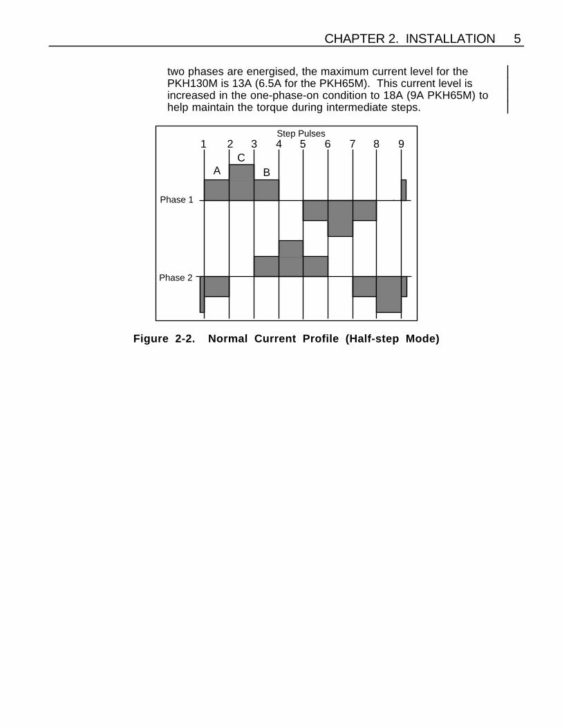
CHAPTER 2. INSTALLATION 5
two phases are energised, the maximum current level for thePKH130M is 13A (6.5A for the PKH65M). This current level isincreased in the one-phase-on condition to 18A (9A PKH65M) tohelp maintain the torque during intermediate steps.
AC
B
Phase 1
Phase 2
1 2 3 4 5 6 7 8Step Pulses
9
Figure 2-2. Normal Current Profile (Half-step Mode)

6 PKH SERIES DRIVE USER GUIDE
Square-off(Switch 5 )
The function of the square-off circuit is to maintain torque output inthe middle speed range when motor current usually falls off due towinding inductance. Figure 2-3 illustrates the current profilesquared-off to the one-phase-on level.
Phase 1
Phase 2
1 2 3 4 5 6 7 8Step Pulses
9
Figure 2-3. Current Profile with Square-off
Normally, you should leave this switch in the OFFposition (default setting). The motor current will automaticallysquare off to the one-phase-on level at approximately 1,600 fullsteps/sec (represented by the profile in Figure 2-2). This is thenormal operating condition, and results in a useful increase in mid-range torque. Turning the switch ON causes the drive to square offpermanently, increasing the average motor current at lowerspeeds. This will give greater low-speed torque. However, it willalso increase both motor noise and motor operating temperature.The function should therefore be used with discretion, making surethe motor case temperature does not exceed 100°C (212°F).
Selecting permanent square-off (Switch 5 ON) in a mini-step modeeffectively returns the drive to the full step current profile.

CHAPTER 2. INSTALLATION 7
Anti-Resonance(Switch 6 )
This switch is normally in the OFF position. This allows the anti-resonance circuit to come into operation at speeds below 200 fullsteps/sec. Turning the switch ON disables the anti-resonance circuitand increases the low-speed torque at the expense of increasedresonance. It is recommended you leave this switch in the OFFposition, thereby reducing the chance of stalling the motor at lowspeeds. However the ON position may be preferable if the motor isheavily loaded.
ResolutionSelect ion
(Switches 7 & 8 )
Use DIP switches 7 & 8 to select the desired motor resolutionaccording to Table 2-3. Be sure to set the indexer to the sameresolution. Consult your indexer user guide for instructions.
CAUTIONDo not change the resolution while power is applied tothe drive.
Resolution(with 200 step/rev
motor)
SteppingMode
DIP SwitchSettings7 8
200 steps/revolution Full step ON OFF400 steps/revolution Half step OFF OFF
1,000 steps/revolution 1/5 step OFF ON2,000 steps/revolution* 1/10 step ON ON
* Default resolution setting for PKH65M/130M
Table 2-3. Resolution Settings
ReferenceSource ( Switch 9 )
DIP switch 9 is used to select the reference source for the currentcontrol system. The switch should be OFF.
Microsteppin g
Description The PKH65M and PKH130M drives are fitted with the MS20Microstep Card which gives improved resolution and smoothnessfrom a standard motor. Microstepping is achieved by proportioningthe currents in the two motor windings so that the rotor takes up aseries of intermediate step positions. In this way a standard 200-step motor may be made to perform 1000 steps/rev (1/5 step mode),or 2000 steps/rev (1/10 step mode).

8 PKH SERIES DRIVE USER GUIDE
Description(continued)
Ideally the intermediate current levels will produce equally-spacedstep positions as well as equal dynamic torque, without exceedingthe dissipation limit of the motor. In practice this can be difficult toachieve and a compromise has to be made. If the current levels areplotted against rotor position the resulting profile resembles asinusoidal shape. The optimum profile varies from one type ofmotor to another, and for this reason the MS20 card has a selectionof 64 alternative profiles which are stored in an Eprom and selectedby an 8-position DIL switch. This switch is located between the twoedge connectors on the drive module, and is accessible after thefront panel has been removed (see Figure 3-2).
A sinusoidally-based profile is obtained with all bit switches in theOFF position. Switches 2 - 6 may be used to set in an increasingbinary number which will cause the profile to progressively "fill out"from a sinewave (see Figure 2-4). Switch 2 is the least significantbit, switch 6 the most significant. By turning on switch 7, increasingthe number in switches 2 - 6 will then trim the profile down towardsa triangular shape. In practice this tends to be more useful than the"filled out" form. Switches 1 and 8 should be left permanently off.
A few examples are shown below in Table 2-4 - a "1" indicates thatthe switch is "on".
Switch position Profile8 7 6 5 4 3 2 10 0 0 0 0 0 0 0 Sinewave0 0 0 0 0 0 1 0 Slight fill-out0 0 1 0 0 0 0 0 Moderate fill-out0 0 1 1 1 1 1 0 Maximum fill-out0 1 0 0 0 0 1 0 Slight trimming0 1 1 0 0 0 0 0 Moderate trimming0 1 1 1 1 1 1 0 Maximum trimming
Table 2-4. Examples of Bit Switch Settings

CHAPTER 2. INSTALLATION 9
Setting Up theMicrostep Card
Choosing the optimum profile for a given motor is best carried outwith equipment which will accurately measure shaft position andtorque. Since this is seldom available, empirical methods arenormally used and can give perfectly acceptable results. Thesetting up should only be attempted when all connections havebeen made and the motor is running.
The logical starting point is with all switches off to give a sinusoidalprofile. Attach a light pointer to the motor shaft (cable ties areideal), and run the motor very slowly. It will be visually apparentwhether the steps are all similar or there is a cyclic variation in stepsize as the shaft rotates. Slowly increase the speed, and the soundfrom the motor will give an idea of the relative torque produced onsuccessive steps. Again a cyclic pulsing sound implies associatedtorque variations.
Switch off, remove the front cover and try setting a trimmed profile(see table above). Repeat the exercise and compare the results.From this it should be clear whether more or less trimming isrequired, so choose another setting and try again. It is usually bestto aim for the smoothest rotation rather than best static positioning.If the application demands significant torque from the motor, repeatthe exercise with the motor loaded. This method usually revealsthe useful range of profiles quite quickly.
TRIMMEDFILLED-OUTSINEWAVE
Figure 2-4. Microstepping Current Profiles

10 PKH SERIES DRIVE USER GUIDE
SystemConnections
Be sure to read the following before operating the drive.
High voltages exist on the motor terminals. All motor connectionsshould therefore be adequately insulated. Pay particular attentionto any unused leads on the motor. If using a motor not suppliedwith a PKH Series system, unused motor leads should beseparated and isolated.
WARNING
Ensure that AC power is disconnected before attemptingto connect or disconnect the motor. Hazardous voltages
are present on the motor connectors.
If you need to change fuses, always disconnect the power from thedrive before removing the drive top panel and wait several minutesfor high voltages to decay.
WiringRecommendations
PKH Series drives use optical isolation on all control signalconnections. This allows direct on-line operation at 120V in theUSA and minimises sensitivity to electrical noise. Note however,that use of an isolating transformer is always recommended, and isessential in order to meet the safety standard chosen todemonstrate compliance with the Low Voltage Directive.
You should observe the following elementary precautions toguarantee trouble-free operation:
• Motor leads should be collectively shielded if they run close topower switching lines, particularly those driving unsuppressedinductive loads.
• Keep high-power connections, such as motor leads, separateand shielded from control signal connections. When it isnecessary to run motor cables in the same conduit as controlsignals, the motor leads should be shielded separately.Connect the shields to ground at one end, and insulate them atthe remote end.
• Ensure that the drive and motor are reliably earthed.

CHAPTER 2. INSTALLATION 11
Insulation rating of the secondary power connections and motorcables should be at least 1000V, where this is between power andsignal circuits. Insulation requirements to mains wiring are higherand will be dependent upon environment and the local machinesafety standards applied. Within secondary and motor circuits, andto earth, insulation rating of 600V is acceptable.
FlashTesting
For internal circuit protection reasons a varistor is fitted between theneutral and earth (ground) mains input wiring within the drive.
Important: If you wish to flash test the completedinstallation from mains to earth, it will be necessary todisconnect and insulate the live and neutral mainsconnections to the drive. Otherwise, the varistor willbreak down when the flash test is applied.
The earth connection and signal I/O should remain connected tothe drive, in order to test the insulation of these circuits.
Direct ACPower
Connections(USA only)
Important: Operation directly from the mains means thatthe drive will not meet the European Safety standardrelating to the Low Voltage Directive. This can only bemet if an isolating transformer is used.
The AC input must be taken both to the motor supply terminals L1and L2 and to the terminals marked 115V AC IN.
This mode of operation allows you to operate the PKH Series ofDrives without an external supply transformer, where suitablemains supplies are available. However, this limits high-speedperformance due to low available voltage.
If you wish to use a transformer rather than direct-on-line operation,see the next section for transformer connection details.

12 PKH SERIES DRIVE USER GUIDE
Motor
2A
2B
1B
1A
EARTH
L1
L2
L3
Motor
115V
SupplyAC In
AC In
NC/StepFaultZero PhaseBoostDirectionStepReset0V
(Red)
(Black)
(Green)
(White)
(Green)
(Black)
(White)
Earth
Line
Neut.
N.C.
120VACSupply
(USA only)
MOTOR
To meet European Safety standardsa mains isolating transformermust be used.
Figure 2-5. PKH Series System Connections - 120V AC supply (USA only)
WARNING - danger of electric shock
Mains voltages are dangerous. Ensure that all terminals are adequatelyinsulated to prevent accidental contact.
TransformerConnections
The Digiplan -T0124 transformer may be used to power thePKH130M Drive, and the T0132 may be used to power thePKH65M Drive. Transformer operation is necessary when the fullhigh-speed torque is required and is always needed in countriesother than the USA.
As illustrated in Figure 2-6, these transformers have a four-windingprimary arrangement. The sample connection shown is theconfiguration for 120VAC. Figure 2-7 shows the connections for240V AC. Table 2-5 identifies the optional primary connections forvarious AC input supply voltages.

CHAPTER 2. INSTALLATION 13
If an alternative transformer is used it must have an earthed screenbetween the primary and secondary windings. For safety reasonsthe insulation between the primary and secondary must beadequate. A minimum of 2300V AC withstand voltage between theprimary and secondary is recommended.
CAUTIONAlways wire the transformer primary first. Then checkthe secondary output voltages on open-circuit BEFOREconnecting to the drive.
Be sure to connect earth ground to the SCN stud on thetransformer and to the drive earth.
For mains wiring, use approved mains cable of at least 0.75mm2
CSA (TO132) or 1.5mm2 CSA (TO124), taking care to keep allmains wiring away from all secondary and signal wiring. Ensurethat the transformer terminations are suitably enclosed to preventoperator contact, either by fitting a suitable cover or enclosing thetransformer within a housing. Note: If a low power secondarywinding is used, e.g., 18-0-18V AC, it must be separately fusedwith an in-line fuse in the wire close to the transformer. The fusevalue should be approximately twice the current rating of thesecondary winding being used (with a time delay characteristic).The 115V 0.3A secondary is fused in the PKH drive.
The PKH130M may need all 14 amps available from the 172VACoutputs. This means that you will have to jumper these two outputstogether as shown in Figure 2-6. Then wire these terminals to thePK130's L1 & L2 inputs. The PKH65M will only require a supply of7 amps. You also need to wire 115VAC from the transformersecondary to the PKH65M/130M as shown.

14 PKH SERIES DRIVE USER GUIDE
20 2010
20 2011 12
1105 6
110 1107 8
120 1201
120 1203 4
AC Line (Black)
Earth Ground
AC Neutral (White)
110
SCN
115
00 016
0
2
TO124
2.75A0.3A
7.0A
7.0A0
0
172
172
018 18
9
MOTOR
2A
2B
1B
1A
EARTH
L1
L2
L3
115V
MOTORSUPPLYAC IN
AC IN
PKH130 DriveSecondary
014 15
Primary
13
AC Supply
SAFETYEARTH
Fuse
Figure 2-6. Transformer Wiring Configuration (Showing 120V AC Setting)
20 2010
20 2011 12
1105 6
110 1107 8
120 1201
120 1203 4
AC Line
Earth Ground
AC Neutral
110
SCN
115
00 016
0
2
TO124
2.75A0.3A
7.0A
7.0A0
0
172
172
018 18
9
MOTOR
2A
2B
1B
1A
EARTH
L1
L2
L3
MOTOR
115V
SUPPLYAC IN
AC IN
PKH130 DriveSecondary
014 15
Primary
13
AC Supply
SAFETYEARTH
Fuse
Figure 2-7. Transformer Wiring Configuration (Showing 240V AC Setting)

CHAPTER 2. INSTALLATION 15
Primary FuseRatings
Primary fuses need to be rated to protect the transformer andsecondary wiring from short circuit faults whilst withstanding theprimary in-rush current at power up. The fuse rating can becalculated as follows:
Fuse rating (A) =Transformer VA × 1.5
Supply volts
Fuses need to be of the anti-surge high breaking capacity type,which have a limited range of values, consequently you may needto select the next highest standard value rather than the calculatedvalue. For example, a 700VA transformer used with a supply of240V will require a 4.4A fuse, consequently the next higheststandard value of 5A will need to be selected.
If the live wire cannot be readily identified, fuse both phaseconductors.
DisconnectDevice
A disconnect device must be provided which isolates all mainssupply current-carrying conductors. If the mains supply ispermanently connected, a switch or circuit breaker must beincluded in the wiring. It must be placed close to the equipment(less than 1 metre) and marked as the disconnecting device for theequipment.

16 PKH SERIES DRIVE USER GUIDE
VoltageAdjustment
Table 2-5 gives details of the terminal connections for the range ofmains input voltages. Input voltages in the range 360 to 460V arefor connection across two phases of a three phase supply.
InputVoltag
e
ConnectAC Line
to:
ConnectAC Neutral
to:Connect Studs:
100 1 9 1,2,3,4; 9,10,11,12110 5 13 5,6,7,8; 13,14,15,16120 1 13 1,2,3,4; 13,14,15,16200 1 10 9 & 2; 11 & 4; 1 & 3; 10 & 12220 5 14 13 & 16; 15 & 8; 14 & 16230 1 14 1 & 3; 13 & 6; 15 & 8; 14 & 16240 1 14 1 & 3; 13 & 2; 15 & 4; 14 & 16360 5 12 9 & 6; 10 & 7; 11 & 8380 5 16 9 & 6; 10 & 7; 11 & 8400 1 12 9 & 2; 10 & 3; 11 & 4420 1 16 9 & 2; 10 & 3; 11 & 4440 5 16 13 & 6; 14 & 7; 15 & 8460 5 16 13 & 6; 14 & 7; 15 & 8
Table 2-5. Optional Transformer Settings
CAUTION
Take particular care when lifting larger transformers. Donot lift them by the terminal plate or cover, as these
could break.
MotorConnections
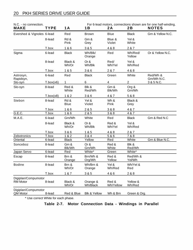
Consult Tables 2-6 & 2-7 or the motor manufacturer's wiringinstructions to determine which motor wires correspond to Phase 1and Phase 2.
After you determine the motor's wiring configuration, connect themotor leads to terminals 2A, 2B, 1A, and 1B as shown in Figure 2-8.Connect one phase of the motor to terminals 1A and 1B, and theother phase to terminals 2A and 2B. To reverse the direction ofrotation relative to the direction control input, interchange theconnections to 1A and 1B.

CHAPTER 2. INSTALLATION 17
The motor windings may be connected either in series or parallelas shown in Figure 2-8. The preferred connection mode dependson the application, since the performance characteristics differ.
Series connection gives double the ampere-turns of a single coil ata given current and there is therefore a significant increase in low-speed torque. However, the inductance per phase is increased tofour times the inductance of one coil, causing the high-speedtorque to drop off more rapidly.
For the same current, parallel connection results in less torque atlow speeds but the torque will be maintained to higher steppingrates. The maximum power obtainable from the motor is greater inthe parallel mode. With a 6-lead motor, the two halves of eachwinding cannot be connected in parallel. However, using one-halfof each winding produces the same torque as an equivalent 8-leadmotor connected in parallel. The advantage of parallel connectionis a reduction in resistive losses which allows a higher current to beused.
It is most important that any unused motor leads are individuallyinsulated, and under no circumstance should they be joinedtogether unless this is specified in the motor connection data. Donot attempt to use a 5-lead motor with this drive.
Motor Cable The recommended gauge for PKH drives is greater or equal to1.5mm2. Use a cable containing four conductors plus the braidedscreen. The temperature rating of the cable must be greater than orequal to the motor case temperature and should be at least 80°C.
Motor Earth The motor body must be reliably earthed. The resistance to theearth star point should be less than 0.1Ω.
Motor Insulation Motor insulation must be rated to withstand at least 750V rms.
WARNING - Hot surface
The case of the motor can become hot. Precautions may need to betaken to prevent operator contact.

18 PKH SERIES DRIVE USER GUIDE
1A
1B
2B
2A
2A
2B
1B
1A
4-LEAD 6-LEAD
8-LEAD(Series)
8-LEAD(Parallel)
2A
2B
1B
1A
2A
2B
1B
1A
Figure 2-8. Typical Motor Connections for 4, 6, and 8 Lead Motors
IMPORTANT
When the PKH drive is powered directly from the ACsupply without the recommended isolating transformer(USA only), the motor leads will be live to the AC supply.It is therefore essential that all motor connections aremade either with double insulated cable or with theaddition of sleeving in the case of flying lead motors.Ensure that any intermediate connections or terminationsbetween motor and drive are also adequately insulated.Motor and cable must have an insulation rating of atleast 1000Vac rms

CHAPTER 2. INSTALLATION 19
N.C. - no connection.MAKE TYPE 1 A 1 B 2 A 2 B NOTESEvershed & Vignoles 6-lead Red Green Blue Yellow Brown & Black N.C.
8-lead Red Green Blue Yellow Link Grey & Pink, linkWhite & Violet
T.box 1 3 4 2 Link 5 & 6, link 7 & 8
Sigma 6-lead Black Orange Red Yellow White/Blk/Org,White/Red/Yel N.C.
8-lead Black Orange Red Yellow Link Wh/Blk & Wh/OrgLink Wh/Red & Wh/Yel
T.box 1 3 2 4 Link 5 & 6,link 7 & 8
Astrosyn, 6-lead Red Red/Wh Grn Grn/Wh White & Black N.C.Rapidsyn,Slo-syn T.box (x6) 1 3 4 5 2 & 6 N.C.
Slo-syn 8-lead Red Red/Wh Grn Grn/Wh Link Black & White, linkOrg & Blk/Wh
T.box (x8) 1 3 5 4 Link 2 & 6, link 7 & 8
Stebon 8-lead Red Yel Pink Blk Link Blue & violet, linkWhite & Grey
T.box 1 2 3 4 Link 5 & 6, link 7 & 8G.E.C. T.box 1 2 3 4 Link 5 & 6, link 7 & 8
M.A.E. 6-lead Grn/Wh Grn Red Red/Wh White & Black N.C.
8-lead Black Orange Red Yellow Link Wh/Blk & Wh/Org, Link Wh/Red & Wh/Yel
T.box 6 5 8 7 Link 1 & 3, link 2 & 4Zebotronics T.box 1 4 5 8 Link 2 & 3, link 6 & 7Oriental 6-lead Black Green Red Blue Yellow & White N.C.
Sonceboz 8-lead Green Grn/Wh Red Red/Wh Link Org & Blk/Wh, linkBlack & White
Japan Servo 6-lead Red Blue Green Yellow 2 x White N.C.
Escap 8-lead Brown Org/Wh Red Yel/Wh Link Brn/Wh & Org,Link Red/Wh & Yellow.
Bodine 8-lead Brown Orange Yellow Red Link Wh/Brn & Wh/Org,link Wh/Yel & Wh/Red.
T.box 1 3 4 2 Link 5 & 7,link 6 & 8
Digiplan/CompumotorRM Motor 8-lead Black Orange Red Yellow LinkWh/Blk & Wh/Org.
Link Wh/Red & Wh/Yel
Digiplan/CompumotorQM Motor 8-lead Red Black White Green Link Yel & Blue
Link Org & Brown
Table 2-6. Motor Connection Data - Windings in Series
20 PKH SERIES DRIVE USER GUIDE
N.C. - no connection. For 6-lead motors, connections shown are for one half-winding.MAKE TYPE 1 A 1 B 2 A 2 B NOTES
Evershed & Vignoles 6-lead Red Brown Blue Black Grn & Yellow N.C.
8-lead Rd & Grn & Blue & Yel &Pink Grey Violet White
T.box 1 & 6 3 & 5 4 & 8 2 & 7
Sigma 6-lead Black Wh/Blk/ Red Wh/Red/ Or & Yellow N.C.Orange Yellow
8-lead Black & Or & Red/ Yel &Wh/Or Wh/Blk Wh/Yel Wh/Red
T.box 1 & 5 3 & 6 2 & 7 4 & 8
Astrosyn, 6-lead Red Black Green White Red/Wh &Rapidsyn, Grn/Wh N.C.Slo-syn T.box(x6) 1 6 4 2 3 & 5 N.C.
Slo-syn 8-lead Red & Blk & Grn & Org &White Red/Wh Blk/Wh Grn/Wh
T.box(x8) 1 & 2 3 & 6 4 & 7 5 & 8
Stebon 8-lead Rd & Yel & Wh & Black &Blue Violet Pink Grey
T.box 1 & 6 2 & 5 3 & 8 4 & 7G.E.C. T.box 1 & 6 2 & 5 3 & 8 4 & 7
M.A.E. 6-lead Grn/Wh White Red Black Grn & Red N.C
8-lead Black & Or & Red & Yel &Wh/Or Wh/Blk Wh/Yel Wh/Red
T.box 3 & 6 1 & 5 4 & 8 2 & 7Zebotronics T.box 1 & 2 3 & 4 5 & 6 7 & 8Oriental 6-lead Black Yellow Red White Grn & Blue N.C.
Sonceboz 8-lead Grn & Or & Red & Blk &Blk/Wh Grn/Wh White Red/Wh
Japan Servo 6-lead Red White* Green White*
Escap 8-lead Brn & Brn/Wh & Red & Red/Wh &Orange Org/Wh Yellow Yel/Wh
Bodine 8-lead Brn & Wh/Brn & Yel & Wh/Yel &Wh/Or Orange Wh/Red Red
T.box 1 & 7 3 & 5 4 & 6 2 & 8
Digiplan/CompumotorRM Motor 8-lead Black & Orange & Red & Yellow &
Wh/Or Wh/Black Wh/Yellow Wh/Red
Digiplan/CompumotorQM Motor 8-lead Red & Blue Blk & Yellow Wh & Brn Green & Org.
* Use correct White for each phase.
Table 2-7. Motor Connection Data - Windings in Parallel

CHAPTER 2. INSTALLATION 21
I/O Connections All input and output signals are optically isolated within the drive.Connections are made to the 8-pin terminal connector on the drivefront panel (see Figure 2-5). Pin 1 is not normally used. Pin 8 isthe common 0V return. Do not use any other terminal as thecommon return for control signals.
If you are using an indexer, refer to the indexer user guide forindexer cable colour codes.
Typical input and output circuits are shown in Figure 2-9. The inputsignal source must be capable of sinking approximately 15mA atthe logic 0 level.
+5V
0V
Output
Internal PKH130 Drive
OUTPUT CIRCUIT
Terminal
Terminal
IsolatedSupply
+5V
0V
Input
INPUT CIRCUIT
Terminal
Terminal
IsolatedSupply
180
2.7k
BC547B
2.7k
Figure 2-9. Typical Input and Output Circuits
NC/Step(Pin 1)
This input is either not connected (NC) or is a positive step input. Itsuse is determined by the setting of link (jumper) LK1. When LK1 isset to position ‘A’ input pin 1 is not connected and the inputconfiguration shown in Figure 2-9 describes the input circuit of stepinput pin 6. When LK1 is set to position ‘B’ inputs 1 and 6 are re-configured, as shown in Figure 2-10. With this circuit arrangementyou can link pin 6 to 0V and pin 1 can be used as a single endedstep input or you can arrange to drive pins 1 and 6 as a differentialinput.

22 PKH SERIES DRIVE USER GUIDE
0V
InputTerminal
Terminal
100
InputTerminal
1
6
8
390pF
Figure 2-10. Input Circuit with Link 1 in Position B
Fault(Pin 2)
This is a composite output signal which goes high in the event of anoverload, short circuit, supply failure, or over temperature fault. It isdriven by an open-collector transistor and should therefore bepulled high by an external resistor when the signal is required. Theresistor should be returned to a voltage not higher than ±30V andshould not permit more than 15mA to flow when the output is low.
Zero Phase (Pin3 )
The zero phase output is low when the translator is in its primarystate. This occurs every 8 steps in the half-step (400 step/rev)mode. The signal will therefore go low 50 times per rev, using a200 step/rev motor. Zero phase corresponds to current flowing fromterminal A to terminal B in each motor phase.
The homing feature of the indexer should be used to establish areference position. The zero phase signal is normally used todefine a precise home position.
The electrical specs are the same for the Fault output. A front-panelLED indicates when the drive is in the zero phase state.
Boost(Pin 4)
Connecting this input to 0V (pin 8) increases the motor current byapproximately 30%. The drive is not rated for continuous operationwith boost applied. If the input is held low, the current will revert toits normal level after 5 seconds. Boost should not be applied formore than 25% of the time, subject to a maximum time of 5seconds. Electrically, this input is internally pulled up and has aninternal current-limiting 180 Ω resistor in series with pin 4.

CHAPTER 2. INSTALLATION 23
Direction(Pin 5)
Taking this input low reverses the direction of motor rotation. Thedirection should only be changed when the motor is stationary orrunning within its start-stop speed range. Do not change thedirection signal within 5µs of the low-going edge of a clock (step)pulse. For Compumotor indexers, connect the Direction+ wire ofthe indexer cable to this input (see Appendix 1). This input iselectrically identical to the Boost input.
S t e p(Pin 6)
The step input is electrically identical to the boost input. A low-going transition on this input causes the motor to advance one step(low-going = from +5V to 0V). The width of the low-going pulseshould be at least 5 µs.
To ensure that the pulse is wide enough, be sure to set yourindexer to the appropriate resolution. If the drive resolution is notthe same as the indexer resolution, the motor may not move. Donot set the indexer resolution higher than 2,000 steps perrevolution. Ensure that the pulse width does not exceed themaximum clock (step) frequency, which can be as high as 100 kHzoperating at 2000 steps/rev or 20kHz at 400 steps/rev.
For operation with Compumotor indexers, connect the Step+ wireof the indexer cable to this input (see Appendix 1).
Reset(Pin 7)
The reset input is also known as shutdown or energise input.When the input is taken low, the drive is de-energised and themotor shaft may be rotated slowly by hand. The action of taking theinput low will also reset a fault condition, provided the cause of thefault has been removed. The drive will re-energise when the inputreturns to a high logic level.
This input is not directly compatible with most Compumotorindexers. If you wish to use the indexer's shutdown output, pleasecontact Digiplan Applications - see title page for contact telephonenumbers.

24 PKH SERIES DRIVE USER GUIDE
CAUTIONDo not rotate the motor at high speed with the drive de-energised. This pumps power back into the drive andmay overload the internal power dump circuit. Similarly,the drive should not be de-energised while the motor isrunning. Applications where the motor may free wheel(i.e., vertical travel application) may result in driverfailure if the motor is de-energised and the load falls.
0V (pin 8) Use this terminal as the common return for the control signals. Donot use any other terminal for this purpose.
SystemMounting
The drive may be mounted in any orientation. However, there are anumber of factors to keep in mind when deciding on the location.
Airflow The temperature range for safe operation is 0°C - 40°C (32°F -104°F). If you mount the PKH Series Drive in an enclosure with anindexer, the horizontal clearance should be no less than 150mm (6inches). Also, do not mount large, heat-producing equipmentdirectly beneath the PKH drive.
Signal Where there is considerable distance between the control system(indexer) and the motor, the drive should generally be located asclose to the control system as possible. Long motor leads seldompresent a problem as long as they have a low resistance and areshielded. Low-level control signals may become prone to noisepick-up or cross-talk problems over long distances.
Environment The operational temperature range for the drive system is 0°C to40°C (32°F to 104°F) and at a relative humidity between 0 and 95%(non-condensing). Make sure the system is stored in temperatureswithin the range from -40°C to 85°C (-40°F to 185°F).
The mains input to the isolating transformer is InstallationCategory III maximum.
The PKH Series of drives can be used in a Pollution Degree 2environment i.e., one in which only non-conductive pollutionoccurs.
The drive system should be installed in an area where there isadequate ventilation above and below the packages. In the finalapplication the equipment must be enclosed to prevent the operator

CHAPTER 2. INSTALLATION 25
coming into contact with any high voltages. This includes thetransformer, drive and motor terminations.

26 PKH SERIES DRIVE USER GUIDE

CHAPTER 3. TROUBLESHOOTING 27
Chapter 3. TROUBLESHOOTING
Description There are three basic protection systems built into the drive. Theseguard against damage caused by overcurrent, power supply faults,and over temperature. Operation of any of these protection circuitswill de-energise (shut down) the drive. The reason for shutdown isindicated by an illuminated LED on the front panel. Provided thecause of the fault has been removed, the drive may be re-energisedby taking control connector pin 7 (Reset) to 0V (pin 8), or bytemporarily removing power. A simplified diagram of the protectioncircuitry is illustrated in Figure 3-1.
0V
FAULT
Internal PKH130 Drive
PROTECTION CIRCUIT
Terminal
Terminal
FaultLatch
ThermalSensor
Over-currentComp.
Phase 1Current
Phase 2Current
Over-voltsComp.
-H.T.-5V+5V+12V
+24V
Over-temp
Over-current
SupplyFault
Figure 3-1. Simplified Protection Circuit
OvercurrentProtection
An overcurrent condition may be caused by incorrect motorconnections, short circuits across the motor terminals, or any othercondition causing excess current to flow. It may also arise if a verylow inductance motor becomes desynchronised duringdeceleration. If any of these circumstances exist, the overcurrentcomparator will set the fault latch, turning on the fault LED andgiving a fault output signal.

28 PKH SERIES DRIVE USER GUIDE
Supply FailureProtection
Should the high-voltage supply rise excessively, or any of the logicsupply rails fall outside preset limits, the supply protection circuitcomes into operation. It functions by using an operational amplifierto compare each of the supply rails with fixed reference levels. Ifthe preset limits are exceeded, the fault latch is set and the supplyfailure LED is illuminated. An excessive rise in the high-voltagesupply may result from failure of the power dump fuse (FS6). Thiscan occur if a very large inertial load is abruptly decelerated.
OvertemperatureProtection
The drive will also shut down if the heatsink temperature reaches85°C (185°F). This is usually caused by inadequate cooling.Persistent over temperature problems indicate a faulty or obstructedfan.
The heatsink temperature is monitored by a thermal sensorattached to the heatsink. The output from the sensor sets the faultlatch directly, and illuminates the over temperature LED on the frontpanel. Time must be allowed for the drive to cool down before itcan be re-energised.
Fault-FindingGuide
If there is no response from the motor, make sure that the motorshaft is free to rotate with the drive switched off. Then turn on thepower and look to see which LEDs are illuminated. If no LEDsilluminate, contact Digiplan Applications Engineering Department -contact telephone numbers are given on the title page of this guide.
Zero Phase This LED normally illuminates on power-up, flashes at low steppingrates, and is illuminated dimly at higher speeds. From power-upthe LED should be illuminated immediately, if not check both inputAC supplies. If the drive has been operating, it is possible the drivewill require a few commanded motor steps when an indexer is usedwith the drive before the LED will illuminate.
If the motor shaft is still free to rotate and there is no audible noisefrom the motor, check the motor connections carefully. Also checkto see if the reset input (pin 7) is not held low. This will de-energisethe motor.

CHAPTER 3. TROUBLESHOOTING 29
If the zero phase LED remains on continuously when the motorshould be running (but is not), either the step pulses are notreaching the drive, or it is not responding to them. Verify that thefollowing operating parameters are set properly:
• Step pulse width is at least 5µs• Indexer resolution is set equal to the drive resolution• Logic level during the pulse is not higher than +1V.
If the step pulse source does not have an open-collector output,check that the logic 1 level is between +4.7V and +7V. Mostindexers come from the factory configured for high resolutiondrives. Refer to the indexer manual for instructions to reduce theresolution.x
Overcurrent Remove power from the drive, disconnect the motor, and thenreapply drive power. If the overcurrent LED is still on, the drive isfaulty. If not, check for short circuits or crossed connections on themotor windings. The resistance on phase 1 should be within ±10%of the resistance on phase 2.
A motor with a very low inductance could also cause this fault. Tryconnecting the motor in series rather than parallel. The currentrating of the motor is halved when changing from parallel to series.The Drive current setting may need to be adjusted to avoid motordamage.
Supply Failure Check the AC supplies to the drive terminal block. If they arecorrect, switch the power off and check the drive fuses. The fusesare located on the drive motherboard and are accessible byremoving the six outer screws on the front panel and removing thefront panel (see Figure 3-2). Fuse ratings are given in Chapter 4,Table 4-1.
Wait 2 minutes after power-off before removing the panel.
If all the fuses are sound, there is almost certainly an internal fault,and the drive should be returned for repair.
CAUTIONWhen replacing the front panel, be careful not todislodge the LED cable or the chassis ground lead.Also, be careful to relocate the motherboard carefullyover the edge connectors.

30 PKH SERIES DRIVE USER GUIDE
DIP Switch
Fuse Locations(front panel removed)
Edge Connector
Remove six outer screws. Then lift offfront panel. Be careful not to break
cables connected to underside.
Edge Connector
MS20
Motherboard
FS1FS2FS3FS4FS5FS6
Fuses
Ground Lead
LED Cable
Figure 3-2. Front Panel Removal and Fuse Locations
Overtem perature This LED indicates that the drive has over-heated. Remove powerfrom the drive and let it cool. If it was previously operatingsatisfactorily, make sure the ventilation slots are not obstructed andthe fan is operating correctly.
Returningthe System
Contact the Parker Automation Technology Centre or themachinery manufacturer who supplied the product. Equipment forrepair should NOT be returned directly to Digiplan without priorauthorisation. Repairs will be carried out by Digiplan but will beprocessed via your supplier.
Digiplan may at their discretion authorise direct shipment to andfrom Poole or Rohnert Park, but only by prior arrangement with yoursupplier. Existing UK and USA customers who purchaseequipment directly from Digiplan should contact Poole or RohnertPark for further information (contact numbers are at the front of thisUser Guide).

CHAPTER 4. HARDWARE REFERENCE 31
Chapter 4. HARDWARE REFERENCE
Specification s
Parameter Value
Amplifiers
TypeMotor resolution (user selectable)
Protection (auto-shutdown if detected):Short circuitBrownoutOvertemperature
Nominal output current (Two-phase-on)
Standby current reduction
Boost current
Maximum stepping frequency
Bipolar recirculating chopperPKH65/130M: 200, 400, 1,000, or 2,000 steps/rev
Phase-to-phase and phase-to-groundIf AC supply drops below 80VACIf heatsink exceeds 85°C (185°F)
PKH65M: 6.5A/phase PKH130M: 13A/phase (DIP switchselectable)
50% of motor current
30% for a maximum of 5 seconds (internally limited)
PKH65/130M: 100kHz @ 2,000 steps /rev
Command Interface
Clock (Step)
Direction
Reset (Shutdown)
Output circuits
Output logic levels
Input impedance
Input logic level
Inputs are fully optically isolated and require a TTL-type signalto operate. >3.5VDC high, <0.8VDC low. User-supplied stepand direction signals must be capable of sinking up to 20mA.
Low going pulse, 5 µs min. width. Max. pulse rate is 100kHz.
Logic high = CW rotation; Logic low = CCW rotation
Logic high = normal operation; Logic low = amplifier disable
Open-collector NPN transistor
+30V max. (off), 15mA max. (on)
180Ω + isolator diode to +5V
Logic 0: ±1V or short-circuit to 0VLogic 1: +4.7V to +7V or open-circuit
Table 4-1. PKH Series Drive Specifications

32 PKH SERIES DRIVE USER GUIDE
Specification sContinue d
Power
Supply voltage
Frequency
Fuses (all slow-blow time delay)FS1, FS2, and FS3 (6.3 x 32mm)
FS4 (6.3 x 32mm)FS5 (6.3 x 32mm)FS6 (6.3 x 32mm)
100 - 480VAC with external transformer; 120VAC (±10%)without external transformer (USA only & not recommended)Supply into PKH drive is 172V max for motor, 120V forfan/logic
PKH130M up to 14APKH65M up to 7A
50/60 Hz
Motor supply (L1, L2, and L3): 25A (PKH130M), 12.5A(PKH65M) high breaking capacityLogic/fan supply: 1A high breaking capacityLogic/fan supply: 1A high breaking capacityPower dump: 2A
Environmental Constraints
Drive operating conditions
StorageHumidity
0° - 40°C (32° - 104°F). Max. heatsink temp. is 85°C (185°F)
-40° - 85°C (-40° - 185°F)0% - 95% (non-condensing)
Motor Compatibility
TypeNumber of LeadsMinimum inductance
2-Phase hybrid or permanent magnet (normally 1.8°)4, 6, or 8 (5 lead not suitable)0.75 mH (PKH130M), 1.5 mH (PKH65M)
Table 4-1. PKH Series Drive Specifications (continued)

CHAPTER 4. HARDWARE REFERENCE 33
DriveDimensions
12.90(327.66)
in (mm) Drive weight = 17 lbs (7.8 Kgs)
3.85
(97.79)5.04
(128.01)
13.50(342.90)
12.30(312.42)
10.90(276.86)
0.87(22.10)
Figure 4-1. PKH Series Drive Dimensions

34 PKH SERIES DRIVE USER GUIDE

APPENDIX 35
Appendix
Connections forParker
Com pumotorIndexers to PKH
Series Drives
PKH 8 pinConnector
OEM 010 DB25
4000DB15
PC23 DB25
3000 DB25
Clock (pin 6) Pin 1 Pin 9 Pin 1 Pin 1Direction (Pin 5) Pin 2 Pin 2 Pin 2 Pin 2Eng/Reset (Pin 7) N/A Pin 12 Pin 17 N/A0 Volts (Pin 8) Pin 7 Pin 13 Pins 14 & 15 Pins 14 & 15
Notes:
1. If motor direction is not the same as the indexer direction,interchange the motor connections between 1A and 1B.
2. The pinouts for the Model 4000 indexer also apply to the 500,6200 and AT6400.
3. The pinouts for the PC23 apply when the Adapter Box isconfigured for single ended operation. See the PC23’s UserManual page 155. Generally, jumpers set in even numberedlocations are for differential operation, odd numbered locations forsingle ended.

36 PKH SERIES DRIVE USER GUIDE

INDEX 37
Index
Airflow 24Anti-resonance 7
Bit switch setup 8Boost 22
Compumotor indexers 23Control signals 24Current profile 5
Default settings 3Dimensions 33DIP switch 3Direction 23Disconnect device 15
Energise 23Environment 24
Fault 22Faultfinding 28Flame barrier 3Flash testing precautions 11Fuse locations 30Fuse ratings 15
Heatsink temperature 28Home position 22
Indexer connections 35Installation 3Installation category 24Insulation requirements 11
LEDs 28
Microstep card setup 9Microstepping 7
Microstepping current profiles 9Motor cable 17motor case temperature 6Motor connections parallel 20Motor connections serial 19Motor connections typical 18
Motor current selection 4Motor direction 35Motor earth 17Motor insulation 17Motor profiles 9Motor resonance 7MS20 Microstep Card 7
NC/Step 21
Open-collector 22Overcurrent 29
Parallel connections 17PKH Series 1PKH Series Drive 1Pollution degree 24, 25Power dump fuse 28
Reference source 7Reset 23Resolution selection 7Resonance 7
Series connections 17Ship kit 2Shutdown 23Signal 24Square-off 6Step 23Step profiles 8Supply failure 29
Temperature operating 24Terminal connections 16TO124 13TO132 13Transformer 1Transformer requirements 13Troubleshooting 27
Zero phase 22Zero phase LED 28

38 PKH SERIES DRIVE USER GUIDE