Embed Size (px)
Citation preview

PL/2021/01508/PPFL - 18 Sandy Hill Rise
Existing C/B Fence 1.8
m high
0
Scale Bar
1 2 3 4 5 10m
Existing Site Plan 1:200
N
0
Scale Bar
1 2 3 4 5 10m
Proposed Site Plan 1:200
N
GARDEN
GARDENPATIO
GARDEN
NEW HOUSE
NEW GARAGE
No 18
No 25
No 8
No 16
SANDY HILL RISE
53005550
5038
4630
2000
5234
11081
10748
10372
SWIC
FWIC
FWIC
HEIGHTTRUNK ∅ SPREAD ∅ No.
TREE SCHEDULE
TE/01 0.10 3 7TE/02 0.10 3 7TE/03 0.10 3 7TE/04 0.05 3 5TE/05 0.10 3 6TE/06 0.10 5 6TE/07 0.10 3 6
C/B Fence 1.8m high
C/B Fence 1.8m highSWIC
9
17
8
25
11
CR
Def
Def
22
18
10
19
15
STRATFORD RO
AD
28
22
16
10
8
16
14
18
18
14
Mapping contents (c) Crown copyright and database rights 2014Ordnance Survey 100035207
0
Scale Bar
10m 50m
Location Plan 1:1250
23
21
note common
boundary
location to
houses
16,18,23,25
boundary
boundary
boundary
boundary
Proposed Street Scene 1:100
Proposed Foreground Street Scene 1:100
No. 18 No. 16No. 25 NEW BUILD
Bo
un
dary
Bo
un
dary
Bo
un
dary
Bo
un
dary
Bo
un
dary
Bo
un
dary
0m
Scale Bar
1 2 3 4 5m
REVISION DATE
client
job
scale date
drawing title
job number drawing number
89 Bills Lane
Shirley
SolihullB90 2PF
T - 0121 744 5806
M - 07788 537 817
www.agarchitecture.co.uk
Figure dimensions to take preference over those scaled. All
dimensions to be checked on site before commencement of any
work or shop drawings. This drawing is to be read in conjunction
with the specification when existing.
copyrightc
AG Architecture
PLANNING
Mr N Fisher
18 Sandy Hill Drive, Shirley
Proposed Elevations/Site plans
Various @ A1 17/05/2021
2021-1025 02
Proposed New build House
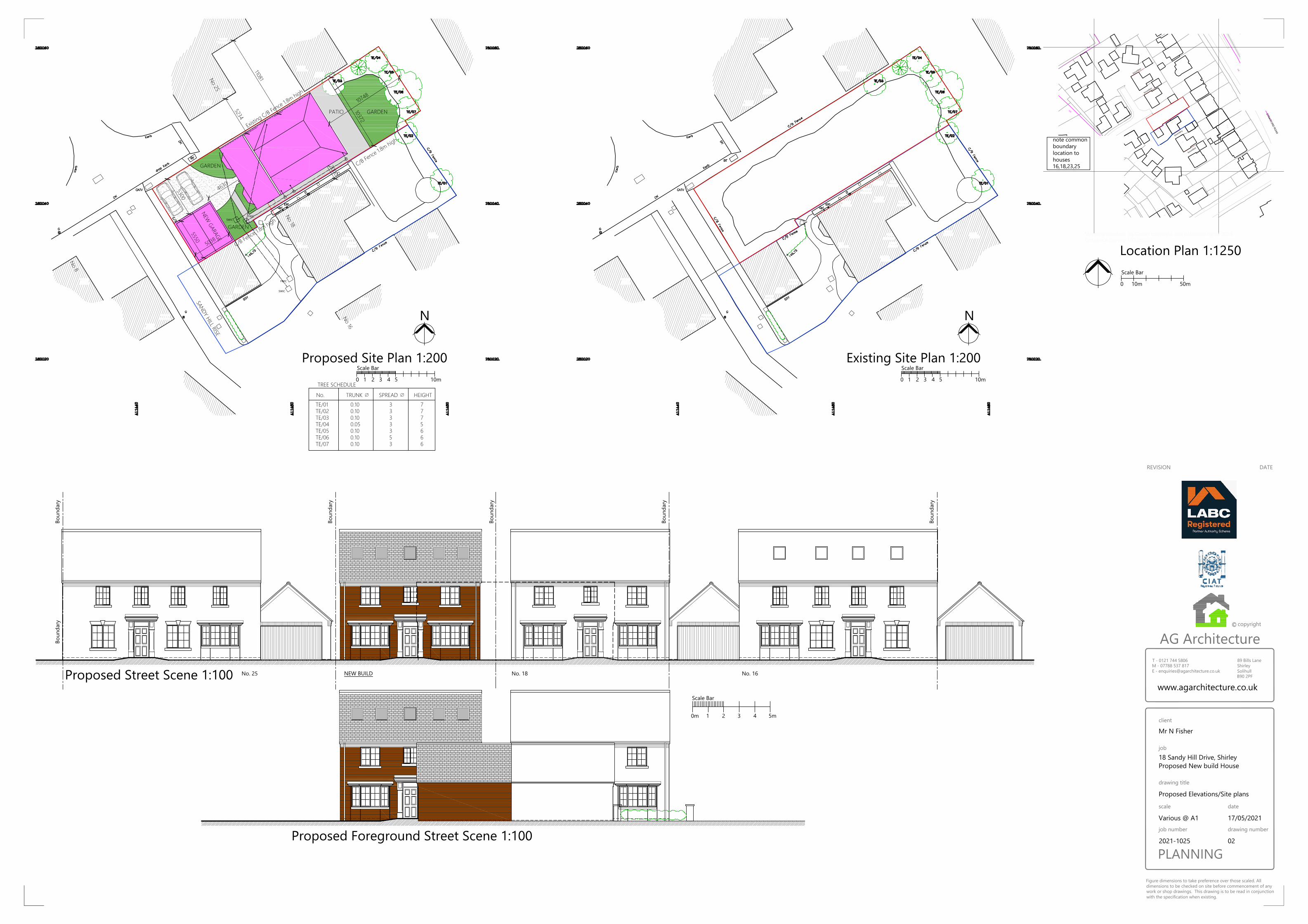
Living Room
Kitchen
Hall Study/playroom
WCClo
aks
6320
1.8m height
Utility
Dining
Family Room
Family
Bathroom
Master Bed 1
18m2
Bed 2
17m2
Bed 3
11.7m2
Bed 4
13m2
DressingRoom
Sto
rag
e
En-suite
En-suite
PPC aluminum sliding doors
Proposed Ground Floor Plan 1:100
Proposed First floor Plan 1:100 Proposed Second floor Plan 1:100
Bed 5
18.5m2
Heating/storage
9000
13500
9000
13500
Proposed Side Elevation 1:100 Proposed Front Elevation 1:100 Proposed Rear Elevation 1:100 Proposed Side Elevation 1:100
0m
Scale Bar
1 2 3 4 5m
En-suiteEn-suite
Proposed Roof Plan 1:100
PPC aluminum sliding doors
Velux windowsVelux windows Facing brickwork
Bays , porch to match existing
New Garage
5785
5245
4630
Obscured glass to bathroomsObscured glass to bathrooms
and utility door
Velux windows
Bed 6
18.5m2
1.8m height
8400
GIA
GROUND FLOOR.......110m2
FIRST FLOOR................108m2
SECOND FLOOR........ 59m2
TOTAL 277m2
Side Elevation 1:100Front Elevation 1:100
4950
DETACHED GARAGE
5010
2505
Typical Section 1:100
Stone cills to match
existing to front
elvation
Facing brick soldier
courses to match
existing to side and
rear elevations
REVISION DATE
client
job
scale date
drawing title
job number drawing number
89 Bills Lane
Shirley
SolihullB90 2PF
T - 0121 744 5806
M - 07788 537 817
www.agarchitecture.co.uk
Figure dimensions to take preference over those scaled. All
dimensions to be checked on site before commencement of any
work or shop drawings. This drawing is to be read in conjunction
with the specification when existing.
copyrightc
AG Architecture
PLANNING
Mr N Fisher
18 Sandy Hill Drive, Shirley
Proposed Plans/elevations
Various @ A1 28/04/2021
2021-1025 01A
Proposed New build House
A Scheme updated 20-05-2021
A3
0 20 METRES
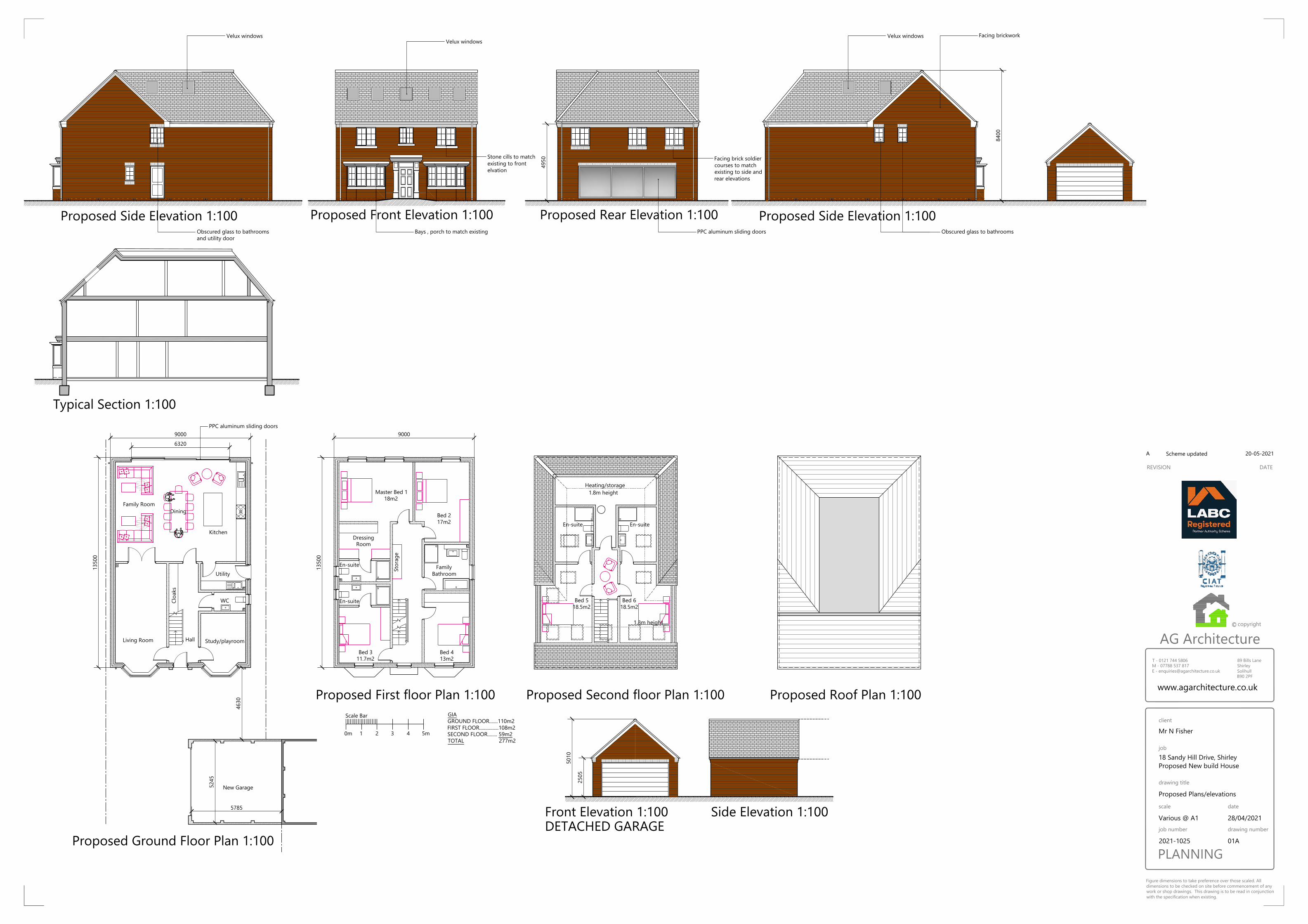
GENERAL
· THE CONTRACTOR IS TO CHECK AND VERIFY ALL CRITICAL DIMENSIONS AND LEVELS BEFORE
WORK STARTS.
· IT IS IMPORTANT TO NOTE THAT THE SAME ACCURACIES IMPLIED BY THE PLOTTING SCALE
ARE EQUALLY APPLICABLE TO DIGITAL DATA SUPPLIED FOR CAD.
· EVERY EFFORT IS MADE TO IDENTIFY ALL VISIBLE ABOVE GROUND FEATURES. HOWEVER
THERE MAY BE ITEMS OBSCURED AT THE TIME OF SURVEY.
· VISIBLE FEATURES IN THE VICINITY OF THE BOUNDARIES, AS SHOWN ON THIS SURVEY, MAY
NOT REPRESENT THE EXTENT OF LEGALLY CONVEYED OWNERSHIP.
· TREE SIZES ARE APPROXIMATE.
April 2021 1:200
Mr & Mrs Fisher
0272 / 01
DRAWING NUMBER
DATEREV
REVISION
DATE SCALE
DRAWING DETAIL
PROJECT TITLE
CLIENT
18 Sandy Hill Rise,
Solihull
Topographical survey as of 26/03/21
DESCRIPTION
20 Collingtree Court
Solihull
B92 7HU
07815 920353
www.dtmsurveys.com
Land and Measured Building Surveys
STATION CO-ORDINATES
LEVELNORTHINGEASTINGSTATION
DTM SURVEYS
HEIGHTTRUNK Ø SPREAD Ø No.
TREE SCHEDULE
North
c DTM Surveys own the copyright of this drawing. Their written consent must be obtained
before this drawing is copied or used for any purpose other than the one for which it was supplied.
FENCE
NOTES
SPOT LEVEL
BUILDING
HEDGE
LEGEND
SURVEY STATION
TREE (INDICATIVE ONLY)
THIS SURVEY IS ORIENTATED TO ORDNANCE SURVEY GRID NORTH. THE SURVEY IS
TO A PLANE GRID. HORIZONTAL MEASUREMENTS TAKEN FROM THIS SURVEY WILL
BE GROUND DISTANCES.
LEVELS RELATED TO ORDNANCE DATUM NEWLYN (ODN).
THE CO-ORDINATE SYSTEM USED FOR THE PRIMARY CONTROL IS OSGB36.
CRITICAL CLEARANCE DIMENSIONS AND HEIGHTS MUST BE CHECKED ON SITE
PRIOR TO CONSTRUCTION.
HEIGHTS HAVE BEEN MEASURED FROM GROUND LEVEL USING NON-CONTACT
METHODS. ACTUAL HEIGHTS MAY VARY.
ABBREVIATIONS
BT BT COVER
C/B CLOSED BOARD FENCE
CATV CABLE TELEVISION COVER
DK DROPPED KERB
DP DOWNPIPE
EiP ELECTRIC POINT
G GULLY
G/DP GULLY AND DOWNPIPE
Gpi GAS PIPE
LP LAMPOST
MH MANHOLE
P/W POST AND WIRE FENCE
RE RODDING EYE
SGY STRIP GULLY
SP SIGNPOST
SV STOP VALVE
TE/? TREE + NUMBER
THL THRESHOLD LEVEL
TP TELEPHONE POLE
TE/01 0.10 3 7
TE/02 0.10 3 7
TE/03 0.10 3 7
TE/04 0.05 3 5
TE/05 0.10 3 6
TE/06 0.10 5 6
TE/07 0.10 3 6
STN/1 411472.80 280039.51 146.87
STN/2 411465.48 280048.88 146.68
STN/3 411455.97 280040.38 146.63
STN/4 411459.92 280025.73 146.83
STN/5 411453.55 280021.90 146.77
STN/6 411431.73 280045.48 146.24