Embed Size (px)
Citation preview

PLACE-N-BONDtm
Partial Underfilm Technology
Alltemated, Inc.
Arlington Heights, IL
United States of America
Testing and Implementation
The information contained in this presentation is the sole property of Alltemated Inc. Any reproduction in part or in whole without the written permission of Alltemated Inc. is prohibited.

Reliability analysis (Underfilm vs. Bare)
To further review the capability of the Partial Underfilm Technology, we
conducted testing similar to the underfill testing that has been presented by
various studies. First, a test vehicle was designed that contained one board
mounted with ten 132 pin BGAs.
A standard .004” solder screen was first placed. Five of the BGAs would
receive no additional support and five would receive a boundary pattern of
partial underfilm of .008” thickness.
The information contained in this presentation is the sole property of Alltemated Inc. Any reproduction in part or in whole without the written permission of Alltemated Inc. is prohibited.

Component placement for testing was conducted on MYDATA SMT line
utilizing standard feeders.
The information contained in this presentation is the sole property of Alltemated Inc. Any reproduction in part or in whole without the written permission of Alltemated Inc. is prohibited.
0.008” thick partial underfilm component shown in standard EIA-481 compliant
carrier tape and SMT feeder.

Test Board Layout
Individual BGA site with Daisy Chained
Solder Pads, Continuity Test Points,
“Tacky Pads” and Underfilm outline
The information contained in this presentation is the sole property of Alltemated Inc. Any reproduction in part or in whole without the written permission of Alltemated Inc. is prohibited.
The boards were reflowed utilizing a
standard SAC 305 profile

Test Vehicle and Drop Test
After reflow, x-ray and electrical test, a
32-gram weight was attached to the
top creating the Test Vehicle for
reliability analysis (pictured at right).
Figure 4(Test Vehicle for drop test analysis)
These .042” thick boards were repeatedly
dropped from a height of six feet onto a steel
gage block. After each drop, a continuity test
was conducted to ensure that the product was
still in working condition using the traces at T+
and T- shown in figure 3.
The information contained in this presentation is the sole property of Alltemated Inc. Any reproduction in part or in whole without the written permission of Alltemated Inc. is prohibited.
1.8 m

RESULTS
After the first few drops, all of the unsupported BGAs failed and completely
fell off of the Test Vehicle altogether. As for the Partial Underfilm Technology
BGAs, although not process optimized, 40% had continuity after 100 drops.
Failed, unsupported BGA
The information contained in this presentation is the sole property of Alltemated Inc. Any reproduction in part or in whole without the written permission of Alltemated Inc. is prohibited.

Drop Test Results
Two of the test vehicle data results are shown below
Drop Test Results Vehicle 8
0
1
2
3
4
5
6
1 9 17 25 33 41 49 57 65 73 81 89 97
Number of Drops
Nu
mb
er
of
Fail
ure
s
Failure for unsupported
Failure for Partial Underfilm
Drop Test Results Vehicle 4
0
1
2
3
4
5
6
1 9 17 25 33 41 49 57 65 73 81 89 97
Number of Drops
Nu
mb
er
of
Fail
ure
s
Failure for unsupported
Failure for Partial Underfilm
As can be seen, the results are significantly different between the unsupported BGAs and Partial
Underfilm supported BGAs.
The information contained in this presentation is the sole property of Alltemated Inc. Any reproduction in part or in whole without the written permission of Alltemated Inc. is prohibited.

PLACE-N-BOND Design Guidelines - Part Selection Guide
Currently Supporting Various BGA Packages: 1mm down to .4mm pitch
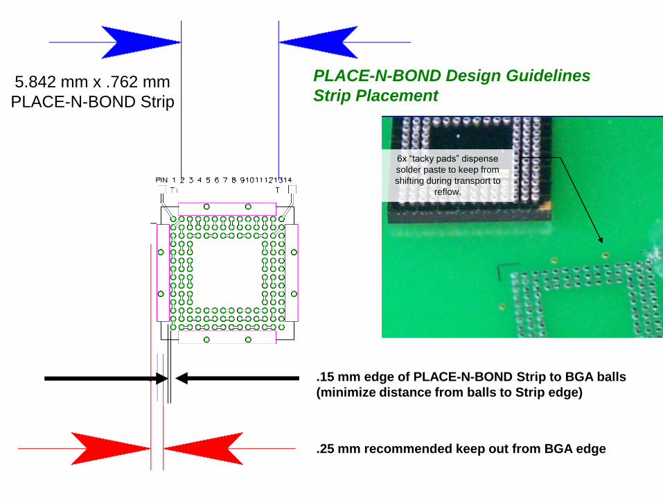
5.842 mm x .762 mm
PLACE-N-BOND Strip
6x “tacky pads” dispense
solder paste to keep from
shifting during transport to
reflow.
.25 mm recommended keep out from BGA edge
.15 mm edge of PLACE-N-BOND Strip to BGA balls
(minimize distance from balls to Strip edge)
PLACE-N-BOND Design Guidelines
Strip Placement
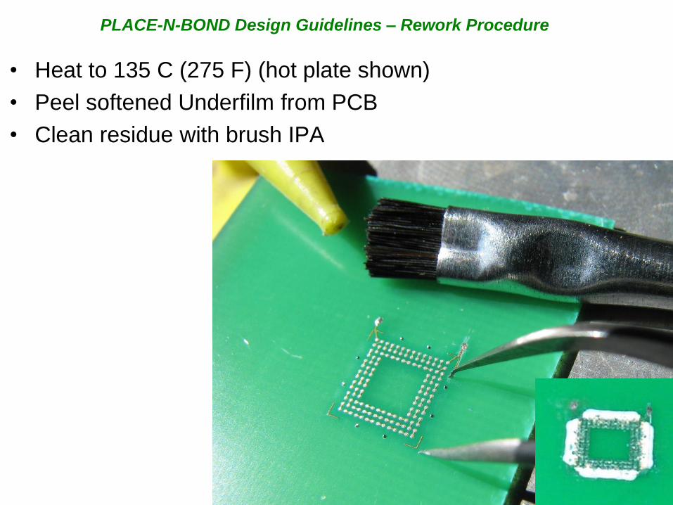
• Heat to 135 C (275 F) (hot plate shown)
• Peel softened Underfilm from PCB
• Clean residue with brush IPA
PLACE-N-BOND Design Guidelines – Rework Procedure
DISCUSSION
Utilizing off the shelf PLACE-N-BONDTM and Topline
components we were able to demonstrate a significant
improvement in solder joint reliability.
We know that the costs for implementation, training,
maintenance, equipment and general overhead are
insignificant compared to that of traditional underfill
technology. The individual films are a few pennies in high
volume.
Some additional benefits are; the complete migration of the
technology from prototype to production facilities, OEM’s
can move the manufacturing process without concern for
capability with PLACE-N-BONDTM technology and
PLACE-N-BONDTM is reworkable improving final yield.
The information contained in this presentation is the sole property of Alltemated Inc. Any reproduction in part or in whole without the written permission of Alltemated Inc. is prohibited.

CONCLUSION
By utilizing the PLACE-N-BONDTM Technology, lead-free
assemblies can be greatly improved without investing in
additional equipment, factory space or PCB space.
Through careful design consideration, the process can be
optimized to improve the yield and performance of
electronic devices. This technology is currently in high
volume production and has become the preferred low
cost solution to get products to pass drop testing
requirements.
Contacts:
Steve Hall [email protected]
[email protected] mobile 1-847-477-7587 USA
The information contained in this presentation is the sole property of Alltemated Inc. Any reproduction in part or in whole without the written permission of Alltemated Inc. is prohibited.

Section view:
BGA132 .5mm pitch SAC 305
Reference photo 3
The information contained in this presentation is the sole property of Alltemated Inc. Any reproduction in part or in whole without the written permission of Alltemated Inc. is prohibited.
PLACE-N-BOND Underfilm
Tacky Pad
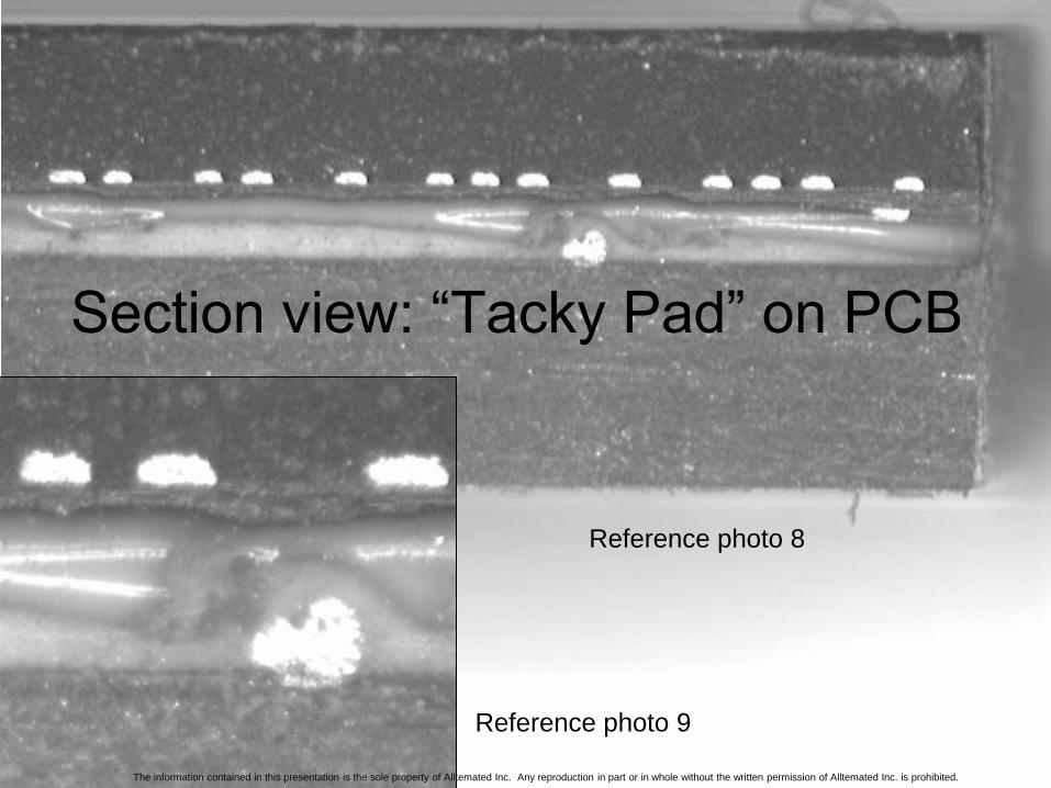
Section view: “Tacky Pad” on PCB
Reference photo 9
Reference photo 8
The information contained in this presentation is the sole property of Alltemated Inc. Any reproduction in part or in whole without the written permission of Alltemated Inc. is prohibited.

Market ComparisonPLACE-N-BOND
UnderfilmFluxing Underfill Underfill
Pick & Place from Tape & Reel YES no no
Re-workable YES no/maybe no/maybe
Eliminates an entire factory process YES no no
Compatible with ANY solder paste YES no YES
Decreased factory cycle time YES $ $
Factory floor space required NO $ $
Dispensing equipment needed NO $$ $$$
Secondary curing oven needed NO NO $$
Capital equipment needed NO $$ $$$
Adds time and equipment NO $$ $$$
Fumes emitted NO yes yes
Limited Shelf life NO yes yes
Air Entrapment Possible NO yes yes
Cure rate / temp. control needed NO yes yes
Cleaning required NO maybe maybe
Pre-bake required NO maybe maybe
Provides maximum reliability maybe maybe maybe

Winner “Best new Product”
SMT VISION AWARD2010
Presented at IPC/APEX
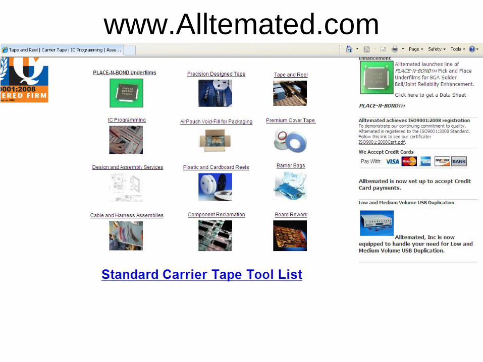
www.Alltemated.com