Embed Size (px)
Citation preview
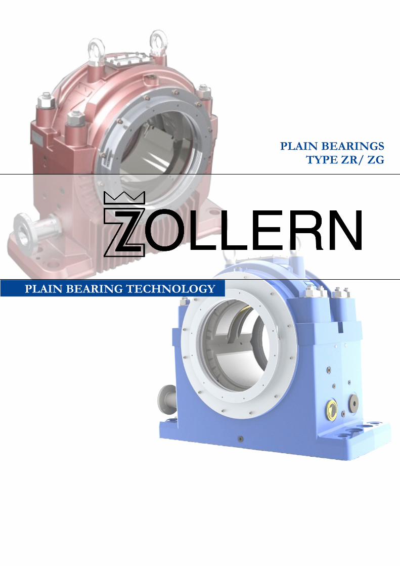
PLAIN BEARINGS TYPE ZR/ ZG
PLAIN BEARING TECHNOLOGY
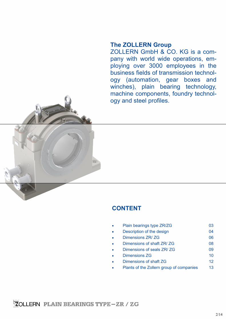
The ZOLLERN Group ZOLLERN GmbH & CO. KG is a com-pany with world wide operations, em-ploying over 3000 employees in the business fields of transmission technol-ogy (automation, gear boxes and winches), plain bearing technology, machine components, foundry technol-ogy and steel profiles.
2/14
CONTENT
Plain bearings type ZR/ZG 03
Description of the design 04
Dimensions ZR/ ZG 06
Dimensions of shaft ZR/ ZG 08
Dimensions of seals ZR/ ZG 09
Dimensions ZG 10
Dimensions of shaft ZG 12
Plants of the Zollern group of companies 13
3 Heat dissipation
N natural cooled by convection
Z lubrication by oil circulation with
external oil cooling
X lubrication by oil circulation with
external oil cooling for high oil
throughput
W finned water cooler in the oil
sump
U recirculating oil pump and
natural cooling
T recirculating oil pump and
water cooler in the oil sump
2 Type of housing
R pedestal bearing, finned
G pedestal bearing, smooth
1 Type Z
4 Shape of bore and type of lubrication
C plain cylindrical bore without oil ring
L plain cylindrical bore with loose oil ring
F plain cylindrical bore with oil disk
Y two-lobe bore without oil ring
V four-lobe bore without oil ring
K journal tilting pads without oil ring
5 Geometry of thrust bearing
Q without thrust capability
B plain white metal lined shoulders
with oil grooves
K tapered land thrust faces for
both sense of rotation
D tapered land thrust faces for
one sense of rotation
A round tilting thrust pads,
cup spring supported
6 Size
7 Shaft diameter
Example for the nomination of a complete bearing
Z R N L B 35-355
ZOLLERN pedestal bearing, finned bearing,
natural cooled by convection, plain cylindrical bore
with loose oil ring, plain white metal lined shoulders
with oil grooves (locating or non-locating bearing),
size 35, for shaft diameter 355 mm.
The nomination of the different bearings is acc.
to the following table:
Nomination of bearings
3/14
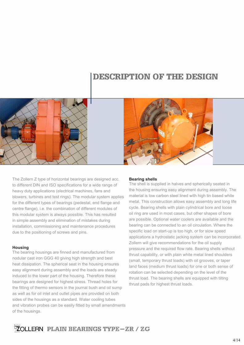
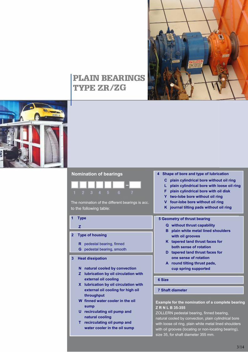
The Zollern Z type of horizontal bearings are designed acc.
to different DIN and ISO specifications for a wide range of
heavy duty applications (electrical machines, fans and
blowers, turbines and test rings). The modular system applies
for the different types of bearings (pedestal, end flange and
centre flange), i.e. the combination of different modules of
this modular system is always possible. This has resulted
in simple assembly and elimination of mistakes during
installation, commissioning and maintenance procedures
due to the positioning of screws and pins.
Housing The bearing housings are finned and manufactured from
nodular cast iron GGG 40 giving high strength and best
heat dissipation. The spherical seat in the housing ensures
easy alignment during assembly and the loads are steady
induced to the lower part of the housing. Therefore these
bearings are designed for highest stress. Thread holes for
the fitting of thermo sensors in the journal bush and oil sump
as well as for oil inlet and outlet pipes are provided on both
sides of the housings as a standard. Water cooling tubes
and vibration probes can be easily fitted by small amendments
of the housings.
Bearing shells The shell is supplied in halves and spherically seated in
the housing ensuring easy alignment during assembly. The
material is low carbon steel lined with high tin based white
metal. This construction allows easy assembly and long life
cycle. Bearing shells with plain cylindrical bore and loose
oil ring are used in most cases, but other shapes of bore
are possible. Optional water coolers are available and the
bearing can be connected to an oil circulation. Where the
specific load on start-up is too high, or for slow speed
applications a hydrostatic jacking system can be incorporated.
Zollern will give recommendations for the oil supply
pressure and the required flow rate. Bearing shells without
thrust capability, or with plain white metal lined shoulders
(small, temporary thrust loads) with oil grooves, or taper
land faces (medium thrust loads) for one or both sense of
rotation can be selected depending on the level of the
thrust load. The bearing shells are equipped with tilting
thrust pads for highest thrust loads.
4/14
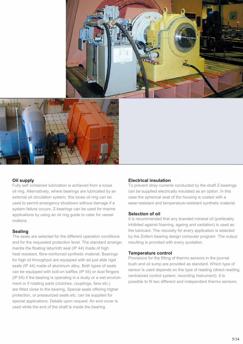
Oil supply Fully self contained lubrication is achieved from a loose
oil ring. Alternatively, where bearings are lubricated by an
external oil circulation system, this loose oil ring can be
used to permit emergency shutdown without damage if a
system failure occurs. Z-bearings can be used for marine
applications by using an oil ring guide to cater for vessel
motions.
Sealing The seals are selected for the different operation conditions
and for the requested protection level. The standard arrange-
mentis the floating labyrinth seal (IP 44) made of high
heat resistant, fibre-reinforced synthetic material. Bearings
for high oil throughput are equipped with ad just able rigid
seals (IP 44) made of aluminum alloy. Both types of seals
can be equipped with bolt-on baffles (IP 55) or dust flingers
(IP 54) if the bearing is operating in a dusty or a wet environ-
ment or if rotating parts (clutches, couplings, fans etc.)
are fitted close to the bearing. Special seals offering higher
protection, or pressurized seals etc. can be supplied for
special applications. Details upon request. An end cover is
used while the end of the shaft is inside the bearing.
Electrical insulation To prevent stray currents conducted by the shaft Z-bearings
can be supplied electrically insulated as an option. In this
case the spherical seat of the housing is coated with a
wear-resistant and temperature-resistant synthetic material.
Selection of oil It is recommended that any branded mineral oil (preferably
inhibited against foaming, ageing and oxidation) is used as
the lubricant. The viscosity for every application is selected
by the Zollern bearing design computer program. The output
resulting is provided with every quotation.
Temperature control Provisions for the fitting of thermo sensors in the journal
bush and oil sump are provided as standard. Which type of
sensor is used depends on the type of reading (direct reading,
centralized control system, recording instrument). It is
possible to fit two different and independent thermo sensors.
5/14
D
(H7) B b1 b2 b3 b13
d1/d2
d3 d5 d7 d8 d9 d10 d11 d12 Dm Dz ZD Pads per side
d13 d14 d15 D171)
35
300 315 335 355 375 400
254 254 254 254
263,5 263,5
300 562 460 360
300 315 335 355 375 400
480 480 480 480 525 525
G3/4 G3 G1 18 M10(12x)
320 335 355 375 395 420
385 400 425 450 470 495
390 405 425 445 455 470
63 63 63 63 50 50
16 18 18 20 24 24
600 640 55
para M42
20
45
375 400 425 450 475 500
318,8 318,8 318,8 318,8 318,8 318,8
375 652 550 530
375 400 425 450 475 500
530 530 530 600 600 600
G3/4 G3 G1 18 M10(12x)
400 425 450 475 500 525
480 505 530 555 580 605
485 510 535 560 580 590
80 80 80 80 63 63
16 18 18 20 26 26
730 780 62
para M48
20
SIZ
E
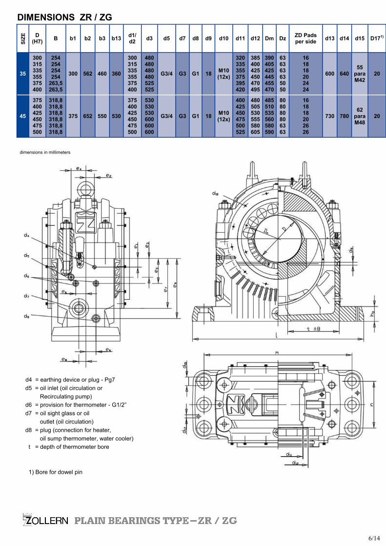
DIMENSIONS ZR / ZG
d4 = earthing device or plug - Pg7
d5 = oil inlet (oil circulation or
Recirculating pump)
d6 = provision for thermometer - G1/2”
d7 = oil sight glass or oil
outlet (oil circulation)
d8 = plug (connection for heater,
oil sump thermometer, water cooler)
t = depth of thermometer bore
1) Bore for dowel pin
dimensions in millimeters
6/14
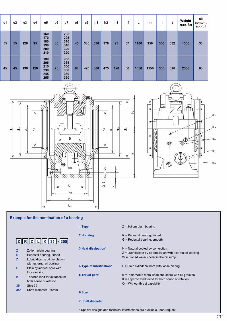
Example for the nomination of a bearing
-
Z Zollern plain bearing
R Pedestal bearing, finned
Z Lubrication by oil circulation,
with external oil cooling
L Plain cylindrical bore with
loose oil ring
K Tapered land thrust faces for
both sense of rotation
35 Size 35
355 Shaft diameter 355mm
Z R Z L K 355 35
e1 e2 e3 e4 e5 e6 e7 e8 e9 h1 h2 h3 h4 L m n t Weight
appr. kg
oil content appr. l
55 55 120 95
160 170 180 190 200 210
65
295 295 310 310 320 320
45 385 530 370 95 57 1100 950 300 332 1300 33
45 45 130 120
190 205 215 230 245 255
75
335 335 350 350 360 360
90 420 600 475 120 60 1350 1150 355 396 2300 63
1 Type Z = Zollern plain bearing
2 Housing R = Pedestal bearing, finned
G = Pedestal bearing, smooth
3 Heat dissipation* N = Natural cooled by convection
Z = Lubrification by oil circulation with external oil cooling
W = Finned water cooler in the oil sump
4 Type of lubrification* L = Plain cylindrical bore with loose oil ring
5 Thrust part* B = Plain White metal lined shoulders with oil grooves
K = Tapered land faced for both sense of rotation
Q = Without thrust capability
6 Size
7 Shaft diameter
* Special designs and technical informations are available upon request.
7/14
D¹ b20² b21³ b22 d24 b38 B39 d30 D31 (e8)
d33 d51 R1 R2 R3 D47 (e8) ————
D32
35
300 315 335 355 375 400
300,5 315 360 115 335 130
385 400 425 450 470 495
300, 315
335, 355
375, 400
315/300 355/335 400/375 450/425
300/—- 335/315 375/355 425/400
335 355 375 400 425 450
458 473 493 513 510 525
8 12 2,5
45
375 400 425 450 475 500
375,5 400 445 120 425 130
480 505 530 555 580 605
375, 400
425, 450
500, 530
400/375 450/425 500/475 560/530
375/—- 425/400 475/450 530/500
425 450 475 500 530 560
570 595 620 645 648 658
10 16 4
SIZ
E
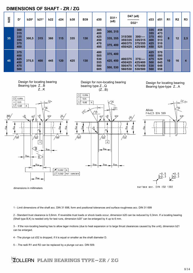
DIMENSIONS OF SHAFT - ZR / ZG
4
5
1 - Limit dimensions of the shaft acc. DIN 31 698, form and positional tolerances and surface roughness acc. DIN 31 699
2 - Standard trust clearance is 0,6mm. If reversible trust loads or shock loads occur, dimension b20 can be reduced by 0,3mm. If a locating bearing
(Shell type B,K) is needed only for test runs, dimension b20” can be enlarged by 4 up to 6 mm.
3 - If the non-locating bearing has to allow lager motions (due to heat expansion or to large thrust clearances caused by the unit), dimension b21
can be enlarged.
4 - The plunge cut d32 is dropped, if it is equal or smaller as the shaft diameter D.
5 - .The radii R1 and R2 can be replaced by a plunge cut acc. DIN 509.
Alívio
dimensions in millimeters
Design for locating bearing Bearing type Z...B Z...K
Design for non-locating bearing bearing type Z...Q (Z...B)
Design for locating bearing Bearing type-type Z...A
8/14
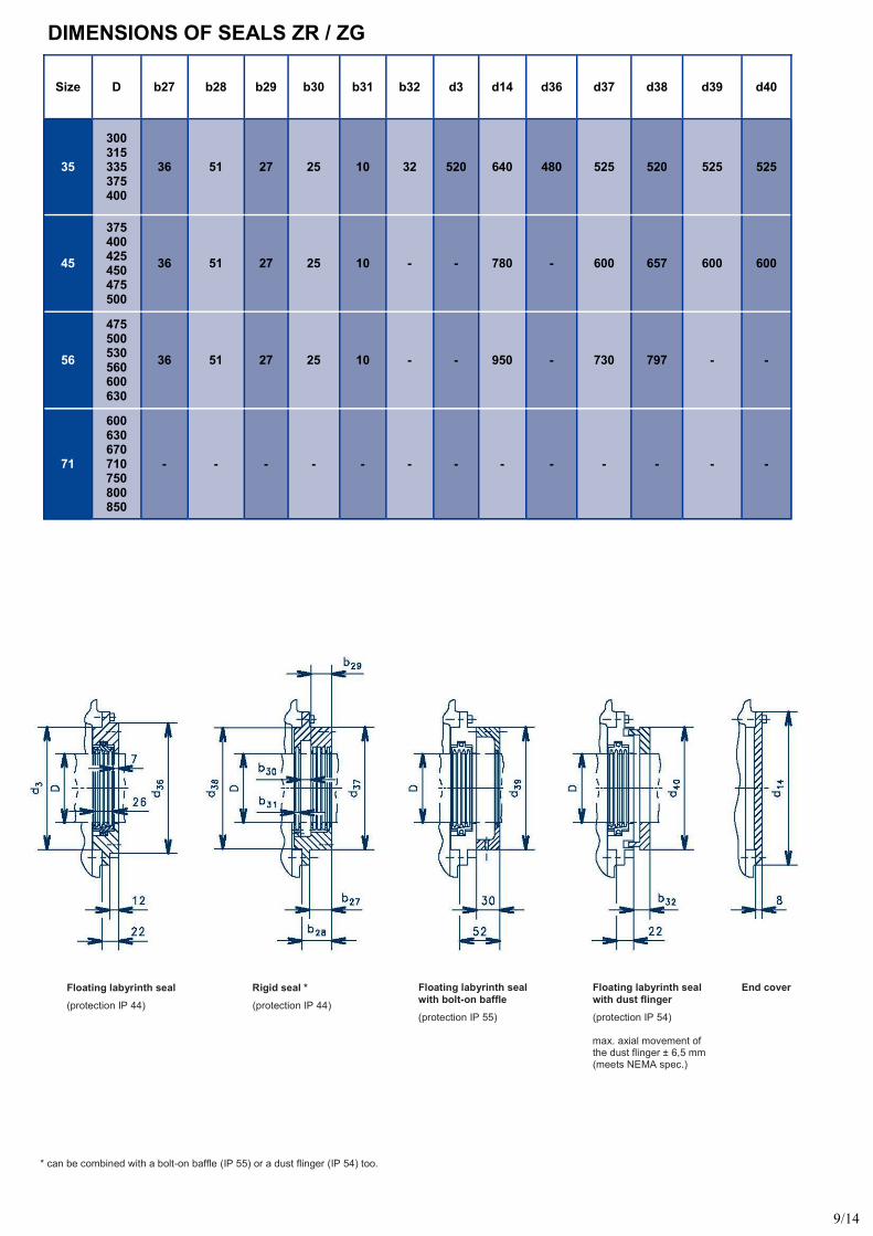
Size D b27 b28 b29 b30 b31 b32 d3 d14 d36 d37 d38 d39 d40
35
300 315 335 375 400
36 51 27 25 10 32 520 640 480 525 520 525 525
45
375 400 425 450 475 500
36 51 27 25 10 - - 780 - 600 657 600 600
56
475 500 530 560 600 630
36 51 27 25 10 - - 950 - 730 797 - -
71
600 630 670 710 750 800 850
- - - - - - - - - - - - -
DIMENSIONS OF SEALS ZR / ZG
Floating labyrinth seal
(protection IP 44)
Rigid seal *
(protection IP 44)
Floating labyrinth seal
with bolt-on baffle
(protection IP 55)
Floating labyrinth seal
with dust flinger
(protection IP 54)
max. axial movement of the dust flinger ± 6,5 mm (meets NEMA spec.)
End cover
* can be combined with a bolt-on baffle (IP 55) or a dust flinger (IP 54) too.
9/14
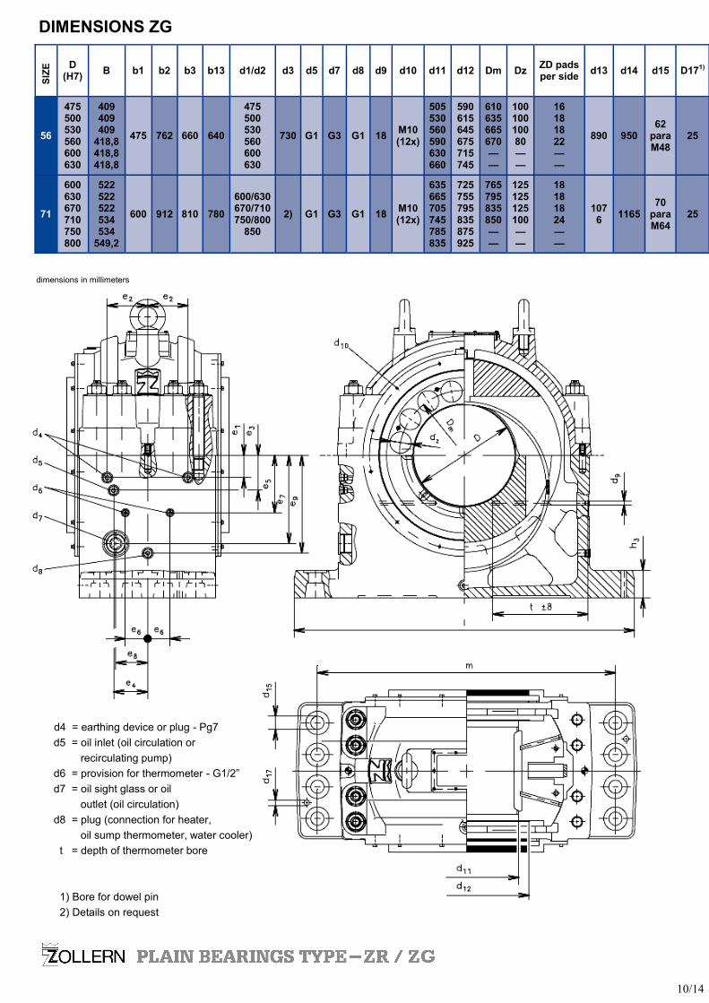
D
(H7) B b1 b2 b3 b13 d1/d2 d3 d5 d7 d8 d9 d10 d11 d12 Dm Dz
ZD pads per side
d13 d14 d15 D171)
56
475 500 530 560 600 630
409 409 409
418,8 418,8 418,8
475 762 660 640
475 500 530 560 600 630
730 G1 G3 G1 18 M10(12x)
505 530 560 590 630 660
590 615 645 675 715 745
610 635 665 670 — —
100 100 100 80 — —
16 18 18 22 — —
890 950 62
para M48
25
71
600 630 670 710 750 800
522 522 522 534 534
549,2
600 912 810 780
600/630 670/710 750/800
850
2) G1 G3 G1 18 M10(12x)
635 665 705 745 785 835
725 755 795 835 875 925
765 795 835 850 — —
125 125 125 100 — —
18 18 18 24 — —
1076
1165 70
para M64
25
SIZ
E
DIMENSIONS ZG
d4 = earthing device or plug - Pg7
d5 = oil inlet (oil circulation or
recirculating pump)
d6 = provision for thermometer - G1/2”
d7 = oil sight glass or oil
outlet (oil circulation)
d8 = plug (connection for heater,
oil sump thermometer, water cooler)
t = depth of thermometer bore
1) Bore for dowel pin
2) Details on request
dimensions in millimeters
10/14
Example for the nomination of a bearing
-
Z Zollern plain bearing
G Pedestal bearing, smooth
Z Lubrication by oil circulation,
with external oil cooling
L Plain cylindrical bore with
loose oil ring
K Tapered land thrust faces for
both sense of rotation
56 Size 56
500 Shaft diameter 500mm
Z G Z L K 500 56
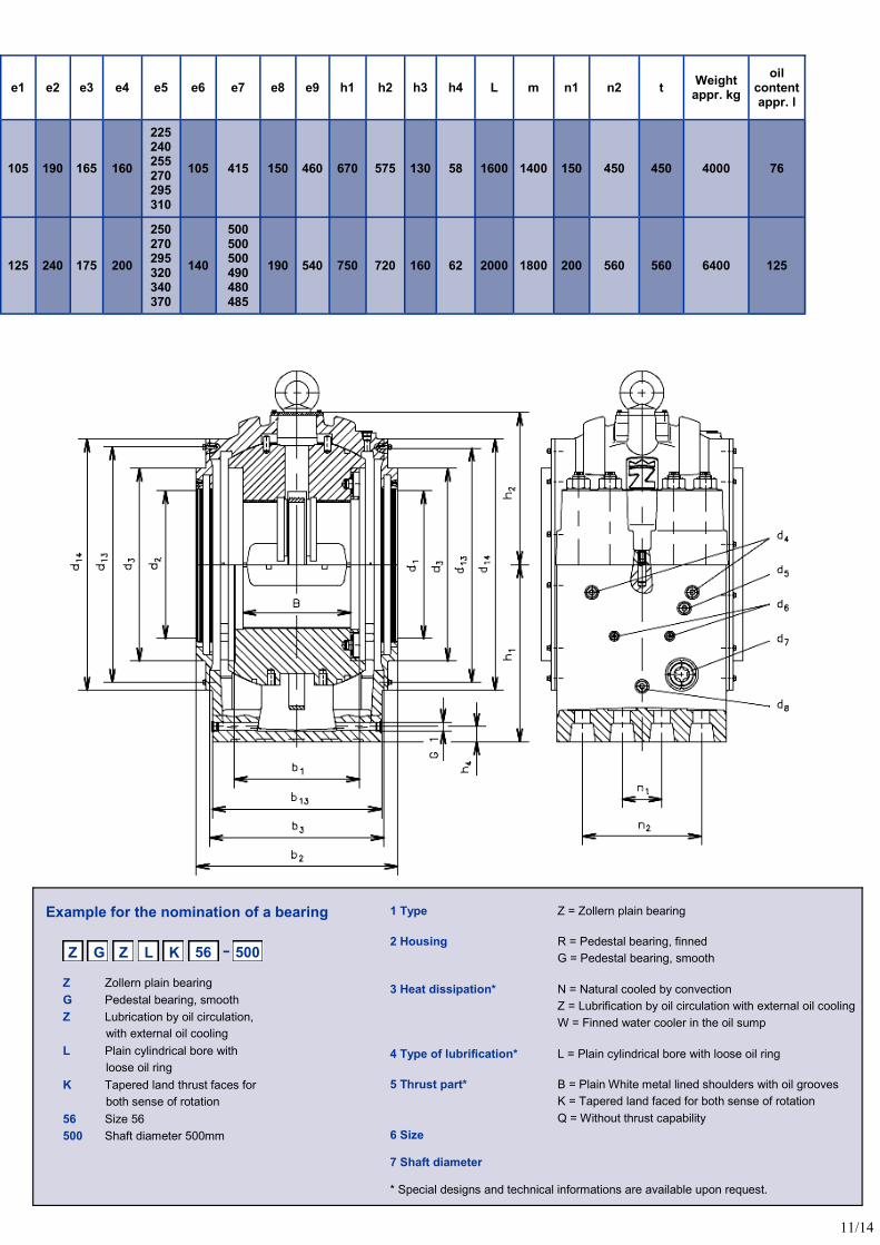
e1 e2 e3 e4 e5 e6 e7 e8 e9 h1 h2 h3 h4 L m n1 n2 t Weight
appr. kg
oil content appr. l
105 190 165 160
225 240 255 270 295 310
105 415 150 460 670 575 130 58 1600 1400 150 450 450 4000 76
125 240 175 200
250 270 295 320 340 370
140
500 500 500 490 480 485
190 540 750 720 160 62 2000 1800 200 560 560 6400 125
1 Type Z = Zollern plain bearing
2 Housing R = Pedestal bearing, finned
G = Pedestal bearing, smooth
3 Heat dissipation* N = Natural cooled by convection
Z = Lubrification by oil circulation with external oil cooling
W = Finned water cooler in the oil sump
4 Type of lubrification* L = Plain cylindrical bore with loose oil ring
5 Thrust part* B = Plain White metal lined shoulders with oil grooves
K = Tapered land faced for both sense of rotation
Q = Without thrust capability
6 Size 7 Shaft diameter * Special designs and technical informations are available upon request.
11/14
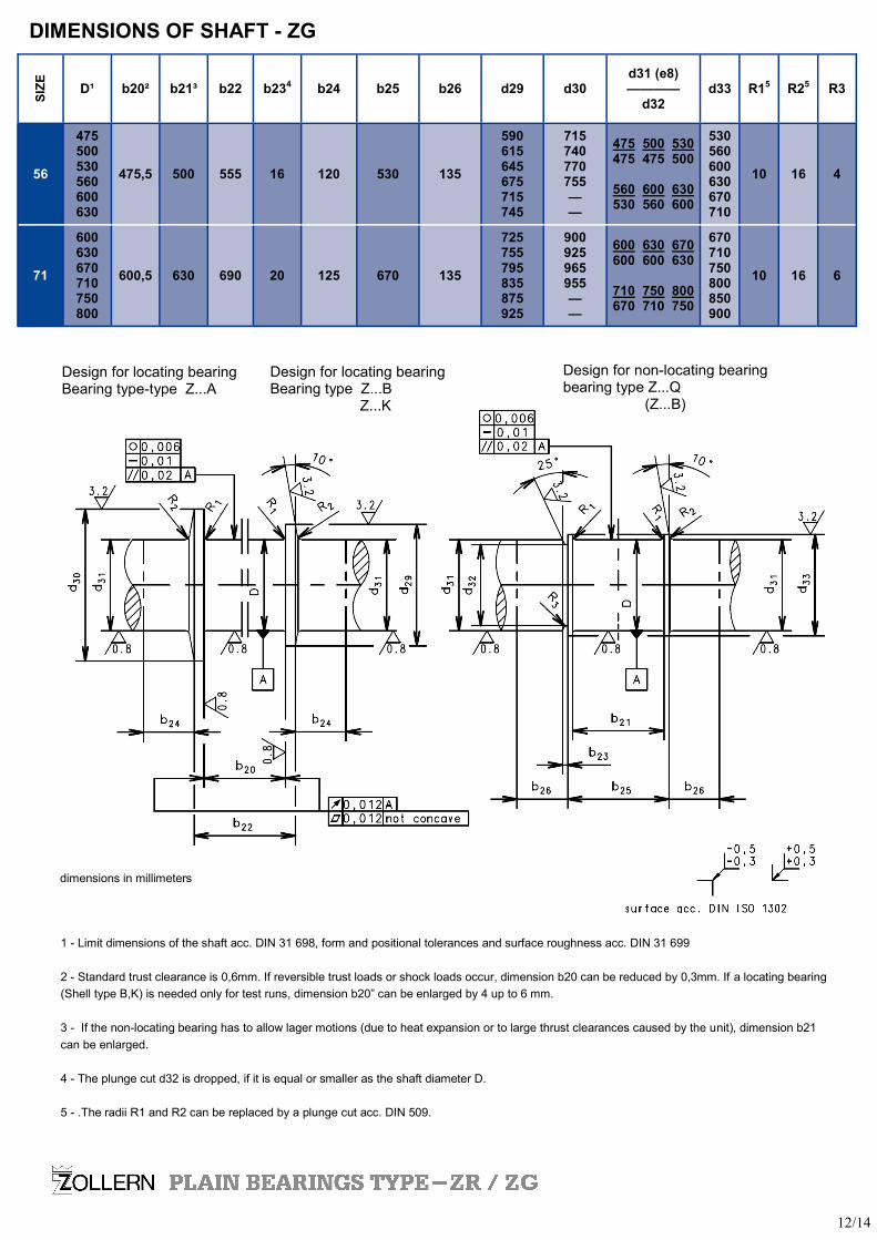
D¹ b20² b21³ b22 b234 b24 b25 b26 d29 d30 d31 (e8) ————
d32 d33 R15 R25 R3
56
475 500 530 560 600 630
475,5 500 555 16 120 530 135
590 615 645 675 715 745
715 740 770 755 — —
475 500 530 475 475 500
560 600 630 530 560 600
530 560 600 630 670 710
10 16 4
71
600 630 670 710 750 800
600,5 630 690 20 125 670 135
725 755 795 835 875 925
900 925 965 955 — —
670 710 750 800 850 900
10 16 6
600 630 670 600 600 630
710 750 800 670 710 750
SIZ
E
DIMENSIONS OF SHAFT - ZG
Design for locating bearing Bearing type Z...B Z...K
Design for non-locating bearing bearing type Z...Q (Z...B)
Design for locating bearing Bearing type-type Z...A
1 - Limit dimensions of the shaft acc. DIN 31 698, form and positional tolerances and surface roughness acc. DIN 31 699
2 - Standard trust clearance is 0,6mm. If reversible trust loads or shock loads occur, dimension b20 can be reduced by 0,3mm. If a locating bearing
(Shell type B,K) is needed only for test runs, dimension b20” can be enlarged by 4 up to 6 mm.
3 - If the non-locating bearing has to allow lager motions (due to heat expansion or to large thrust clearances caused by the unit), dimension b21
can be enlarged.
4 - The plunge cut d32 is dropped, if it is equal or smaller as the shaft diameter D.
5 - .The radii R1 and R2 can be replaced by a plunge cut acc. DIN 509.
dimensions in millimeters
12/14

13/14


Zollern Transmissões Mecânicas Ltda. Av. Manoel Inácio Peixoto, 2147 CEP: 36771-000 - Cataguases-MG - Brasil www.zollern.com.br
Vendas/ Sales Department: Tel: +55 32 3429 5304 / 3429 5305 / 3429 5318 Fax: +55 32 3429 5303 email: [email protected]
Engenharia/ Engineer Department: Tel: +55 32 3429 5307 / 3429 5306 Fax: +55 32 3429 2023 email: [email protected]